EP1530410A2 - Teilchen-Therapieanlage - Google Patents
Teilchen-Therapieanlage Download PDFInfo
- Publication number
- EP1530410A2 EP1530410A2 EP04026311A EP04026311A EP1530410A2 EP 1530410 A2 EP1530410 A2 EP 1530410A2 EP 04026311 A EP04026311 A EP 04026311A EP 04026311 A EP04026311 A EP 04026311A EP 1530410 A2 EP1530410 A2 EP 1530410A2
- Authority
- EP
- European Patent Office
- Prior art keywords
- energy
- charged particle
- particle beam
- orbiting
- acceleration
- Prior art date
- Legal status (The legal status is an assumption and is not a legal conclusion. Google has not performed a legal analysis and makes no representation as to the accuracy of the status listed.)
- Granted
Links
- 238000002727 particle therapy Methods 0.000 title claims abstract description 60
- 239000002245 particle Substances 0.000 claims abstract description 88
- 230000001133 acceleration Effects 0.000 claims abstract description 77
- 230000002159 abnormal effect Effects 0.000 claims abstract description 27
- 238000005452 bending Methods 0.000 claims description 60
- 238000000605 extraction Methods 0.000 claims description 30
- 230000002401 inhibitory effect Effects 0.000 claims description 6
- 230000001678 irradiating effect Effects 0.000 claims description 2
- 238000010884 ion-beam technique Methods 0.000 abstract description 139
- 238000000034 method Methods 0.000 description 22
- 230000008569 process Effects 0.000 description 14
- 206010028980 Neoplasm Diseases 0.000 description 11
- 230000000875 corresponding effect Effects 0.000 description 11
- 201000011510 cancer Diseases 0.000 description 10
- 230000004044 response Effects 0.000 description 8
- 230000008859 change Effects 0.000 description 7
- 238000010586 diagram Methods 0.000 description 6
- 238000005259 measurement Methods 0.000 description 6
- 238000010276 construction Methods 0.000 description 4
- 238000001514 detection method Methods 0.000 description 4
- JCYWCSGERIELPG-UHFFFAOYSA-N imes Chemical compound CC1=CC(C)=CC(C)=C1N1C=CN(C=2C(=CC(C)=CC=2C)C)[C]1 JCYWCSGERIELPG-UHFFFAOYSA-N 0.000 description 4
- 230000001276 controlling effect Effects 0.000 description 3
- 238000006073 displacement reaction Methods 0.000 description 3
- 230000005284 excitation Effects 0.000 description 3
- 230000006870 function Effects 0.000 description 3
- 238000002347 injection Methods 0.000 description 3
- 239000007924 injection Substances 0.000 description 3
- XLYOFNOQVPJJNP-UHFFFAOYSA-N water Substances O XLYOFNOQVPJJNP-UHFFFAOYSA-N 0.000 description 3
- 238000001228 spectrum Methods 0.000 description 2
- OKTJSMMVPCPJKN-UHFFFAOYSA-N Carbon Chemical compound [C] OKTJSMMVPCPJKN-UHFFFAOYSA-N 0.000 description 1
- BGPVFRJUHWVFKM-UHFFFAOYSA-N N1=C2C=CC=CC2=[N+]([O-])C1(CC1)CCC21N=C1C=CC=CC1=[N+]2[O-] Chemical compound N1=C2C=CC=CC2=[N+]([O-])C1(CC1)CCC21N=C1C=CC=CC1=[N+]2[O-] BGPVFRJUHWVFKM-UHFFFAOYSA-N 0.000 description 1
- 229910052799 carbon Inorganic materials 0.000 description 1
- 230000002596 correlated effect Effects 0.000 description 1
- 239000006185 dispersion Substances 0.000 description 1
- 238000005516 engineering process Methods 0.000 description 1
- 230000010355 oscillation Effects 0.000 description 1
- 238000002360 preparation method Methods 0.000 description 1
- 230000002035 prolonged effect Effects 0.000 description 1
- 238000002661 proton therapy Methods 0.000 description 1
- 238000000790 scattering method Methods 0.000 description 1
- 230000036962 time dependent Effects 0.000 description 1
Images


Classifications
-
- H—ELECTRICITY
- H05—ELECTRIC TECHNIQUES NOT OTHERWISE PROVIDED FOR
- H05H—PLASMA TECHNIQUE; PRODUCTION OF ACCELERATED ELECTRICALLY-CHARGED PARTICLES OR OF NEUTRONS; PRODUCTION OR ACCELERATION OF NEUTRAL MOLECULAR OR ATOMIC BEAMS
- H05H13/00—Magnetic resonance accelerators; Cyclotrons
- H05H13/04—Synchrotrons
-
- H—ELECTRICITY
- H05—ELECTRIC TECHNIQUES NOT OTHERWISE PROVIDED FOR
- H05H—PLASMA TECHNIQUE; PRODUCTION OF ACCELERATED ELECTRICALLY-CHARGED PARTICLES OR OF NEUTRONS; PRODUCTION OR ACCELERATION OF NEUTRAL MOLECULAR OR ATOMIC BEAMS
- H05H7/00—Details of devices of the types covered by groups H05H9/00, H05H11/00, H05H13/00
- H05H7/06—Two-beam arrangements; Multi-beam arrangements storage rings; Electron rings
-
- A—HUMAN NECESSITIES
- A61—MEDICAL OR VETERINARY SCIENCE; HYGIENE
- A61N—ELECTROTHERAPY; MAGNETOTHERAPY; RADIATION THERAPY; ULTRASOUND THERAPY
- A61N5/00—Radiation therapy
- A61N5/10—X-ray therapy; Gamma-ray therapy; Particle-irradiation therapy
- A61N2005/1085—X-ray therapy; Gamma-ray therapy; Particle-irradiation therapy characterised by the type of particles applied to the patient
- A61N2005/1087—Ions; Protons
-
- H—ELECTRICITY
- H05—ELECTRIC TECHNIQUES NOT OTHERWISE PROVIDED FOR
- H05H—PLASMA TECHNIQUE; PRODUCTION OF ACCELERATED ELECTRICALLY-CHARGED PARTICLES OR OF NEUTRONS; PRODUCTION OR ACCELERATION OF NEUTRAL MOLECULAR OR ATOMIC BEAMS
- H05H7/00—Details of devices of the types covered by groups H05H9/00, H05H11/00, H05H13/00
- H05H7/001—Arrangements for beam delivery or irradiation
- H05H2007/008—Arrangements for beam delivery or irradiation for measuring beam parameters
Definitions
- the present invention relates to a particle therapy system, and more particularly to a particle therapy system suitable for accelerating an ion beam, such as a proton or heavy ion beam, by an accelerator to be used in medical treatment.
- an ion beam such as a proton or heavy ion beam
- a particle therapy system employing an ion beam, such as a proton or heavy ion beam (hereinafter referred to also simply as a "beam”), for treatment of cancers is designed to be able to irradiate the beam in match with the shape of a diseased part in the body of a patient so that the beam is concentrated to the diseased part.
- a beam such as a proton or heavy ion beam
- adjustment of the beam range in the direction of depth from the body surface of the patient can be realized by adjusting energy of the beam.
- a typical example of accelerators used in the particle therapy system is a synchrotron.
- the synchrotron has an RF cavity for acceleration (hereinafter referred to as an "RF cavity") in which an RF voltage is applied to an orbiting beam and the beam is accelerated to a desired level of energy.
- the beam having been accelerated to the desired level of energy is extracted from the synchrotron, is introduced to an irradiation apparatus through a beam transportation line, and is irradiated to the diseased part (cancer) in the body of the patient lying on a treatment couch.
- RF cavity RF cavity for acceleration
- the irradiation apparatus produces a beam in match with the size of the cancer and the depth thereof from the body surface of the patient, and then irradiates the produced beam.
- the irradiation apparatus is constructed to be able to irradiate the beam based on one of known beam irradiation methods, i.e., a double scattering method (p. 2081 and Fig. 35 of Non-Patent Reference 1; "REVIEW OF SCIENTIFIC INSTRUMENTS", Vol. 64, No. 8 (March 1993), pp. 2079-2093), a wobbling method (p. 2084 and Fig. 41 of Non-Patent Reference 1), and an ion beam scanning method (Patent Reference 1; JP,A 10-118240 and pp. 2092-2093 of Non-Patent Reference 1).
- a double scattering method p. 2081 and Fig. 35 of Non-Patent Reference 1; "REVIEW OF SCIENTIFIC INSTRUMENTS", Vol. 64,
- the synchrotron constituting the accelerator of the particle therapy system is required to control energy of the extracted beam to a set energy level with high accuracy.
- the beam energy requires to be measured with high accuracy. It has hitherto been known to measure the beam energy by employing a water phantom disclosed in Patent Reference 2; JP,A 11-64530 and a multi-leaf Faraday cup described in Non-Patent Reference 2; "BEAM COMMISSIONING OF THE NEW PROTON THERAPY SYSTEM FOR UNIVERSITY OF TSUKUBA", M. Umezawa, et al., Proceedings of 2001 Particle Accelerator Conference, Chicago, USA (2001)).
- Patent Reference 1 proposes a method of dividing the diseased part into a plurality of layers in the direction of depth from the body surface of the patient and scanning the beam for each of the divided layers. To irradiate the beam to a certain layer, the beam energy is adjusted so that the beam reaches just the relevant layer.
- the beam is irradiated to other layer than the relevant layer. From the viewpoint of avoiding such a trouble, it is desired to measure the ion beam before the ion beam is irradiated to the patient after the acceleration of the ion beam has ended.
- An object of the present invention is to provide a particle therapy system capable of confirming energy of an accelerated charged particle beam before the charged particle beam is irradiated to an irradiation target.
- the particle therapy system of the present invention is featured in comprising an energy determination device for determining energy of a charged particle beam orbiting within a circular accelerator after the end of acceleration of the charged particle beam by a circular accelerator. Since the energy determination device determines the energy of the charged particle beam orbiting within the circular accelerator after the end of the acceleration, the energy of the charged particle beam can be confirmed before the charged particle beam is irradiated to the irradiation target.
- the particle therapy system further comprises a beam intensity determination device for determining beam intensity of the charged particle beam orbiting within the circular accelerator after the end of acceleration of the charged particle beam by the circular accelerator.
- a beam intensity determination device for determining beam intensity of the charged particle beam orbiting within the circular accelerator after the end of acceleration of the charged particle beam by the circular accelerator.
- the energy determination device determines that the energy of the charged particle beam orbiting after the end of the acceleration is normal, when a frequency of a radio frequency (RF) wave (e.g., an RF voltage) applied to an RF cavity for acceleration is within a first allowable range after the end of the acceleration and an orbit position of the orbiting charged particle beam after the end of the acceleration is within a second allowable range.
- RF radio frequency
- the charged particle beam orbiting within the circular accelerator is accelerated only when the relationship between the strength of a bending magnetic field and the revolution frequency of the charged particle beam is a predetermined one. Therefore, the energy of the charged particle beam orbiting after the end of the acceleration can be decided if the strength of the bending magnetic field and the revolution frequency of the charged particle beam are known. Also, the strength of the bending magnetic field affects the beam orbit position of the orbiting charged particle beam, and the frequency of the RF wave applied to the charged particle beam for accelerating the same is related to the revolution frequency of the charged particle beam. Accordingly, the energy of the charged particle beam orbiting after the end of the acceleration can be determined based on the frequency of the RF wave applied for acceleration and the orbit position of the charged particle beam.
- the energy determination device determines that the energy of the charged particle beam orbiting after the end of the acceleration is abnormal (differs from a predetermined level of energy), when the frequency of the RF wave after the end of the acceleration is outside the first allowable range and the orbit position of the orbiting charged particle beam after the end of the acceleration is outside the second allowable range.
- the energy determination device determines that the energy of the charged particle beam orbiting after the end of the acceleration is normal, when the strength of the bending magnetic field produced by a bending magnet is within a first allowable range and the orbit position of the orbiting charged particle beam is within the second allowable range.
- the energy of the charged particle beam orbiting after the end of the acceleration can be decided if the strength of the bending magnetic field and the revolution frequency of the charged particle beam are known. Accordingly, the energy of the charged particle beam orbiting after the end of the acceleration can be determined based on the strength of the bending magnetic field and the frequency of the RF wave applied for acceleration.
- the particle therapy system further comprises a first safety device for permitting extraction of the charged particle beam from the circular accelerator when the energy determination device determines that the energy of the orbiting charged particle beam is normal, and for inhibiting extraction of the charged particle beam from the circular accelerator when the energy determination device determines that the energy of the orbiting charged particle beam is abnormal.
- a first safety device for permitting extraction of the charged particle beam from the circular accelerator when the energy determination device determines that the energy of the orbiting charged particle beam is normal, and for inhibiting extraction of the charged particle beam from the circular accelerator when the energy determination device determines that the energy of the orbiting charged particle beam is abnormal.
- the particle therapy system further comprises a second safety device for permitting extraction of the charged particle beam from the circular accelerator when the beam intensity determination device determines that the beam intensity of the orbiting charged particle beam is normal, and for inhibiting extraction of the charged particle beam from the circular accelerator when the beam intensity determination device determines that the beam intensity of the orbiting charged particle beam is abnormal.
- a second safety device for permitting extraction of the charged particle beam from the circular accelerator when the beam intensity determination device determines that the beam intensity of the orbiting charged particle beam is normal, and for inhibiting extraction of the charged particle beam from the circular accelerator when the beam intensity determination device determines that the beam intensity of the orbiting charged particle beam is abnormal.
- the energy of the accelerated charged particle beam can be confirmed before the charged particle beam is irradiated to the irradiation target.
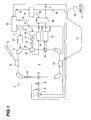
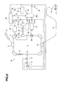
- a particle therapy system according to a first embodiment of the present invention will be described with reference to Fig. 1.
- a particle therapy system 1 of this first embodiment comprises a synchrotron 3 constituting a circular accelerator, a beam transportation system 15, and an irradiation field forming apparatus (charged particle beam irradiation apparatus) 16.
- the irradiation field forming apparatus will be referred to as an "irradiation apparatus" hereinafter.
- the synchrotron 3 comprises an injection device 4, a plurality of bending magnets 5, an RF knockout electrode 6, an RF cavity 10 for acceleration, and a beam extraction deflector 13, which are installed along a beam orbit. Though not shown, a plurality of quadrupole magnets are also installed in the synchrotron 3.
- a magnet power supply 23 is connected to the bending magnets 5.
- the RF knockout electrode 6 is connected to an RF oscillator (RF power supply) 7 through an extraction switch (first on/off device) 8 and a gate switch (second on/off device) 9 serving as a first safety device.
- the RF oscillator 7 serves as an RF oscillator for beam extraction.
- Another RF oscillator 11 applies a predetermined RF voltage to the RF cavity 10 through a power amplifier 12 under control of an RF controller 24.
- the RF oscillator 11 serves as an RF oscillator for beam acceleration.
- a cavity voltage monitor 18 associated with the RF cavity 10 is connected to a frequency counter 19.
- a beam position monitor 20 disposed in the synchrotron 3 is connected to a beam signal processing unit (radial beam position measuring device) 21.
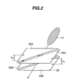
- the beam position monitor 20 has two sets of electrodes each in the form of a triangular flat plate. One set is constructed of two electrodes 55A, 55B arranged opposite to each other with the beam orbit passing between them, and the other set is constructed of two electrodes 56A, 56B arranged opposite to each other with the beam orbit passing between them. Those electrodes are all connected to the beam signal processing unit 21.
- the frequency counter 19 and the beam signal processing unit 21 are connected to an energy judgment processing unit 26.
- the energy judgment processing unit 26 is connected to an accelerator controller 22 and the gate switch 9.
- the accelerator controller 22 is in turn connected to a timing controller 25, the energy judgment processing unit 26, the magnet power supply 23, and the RF controller 24.
- the timing controller 25 is connected to the energy judgment processing unit 26 and the extraction switch 8.
- the accelerator controller 22 and the timing controller 25 serve as control units for supervising the various units of the synchrotron 3.
- the accelerator controller 22 manages control setting values for the relevant units, and the timing controller 25 manages timings in operations of the relevant units.
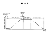
- the synchrotron 3 is operated by repeating successive stages of injecting and capturing an ion beam (heavy particle beam such as a proton beam or a carbon ion beam), i.e., a charged particle beam, accelerating the ion beam to a set level of energy, extracting the ion beam having reached the set level of energy, and decelerating the ion beam. Operation timings of those control stages of injection-and-capture, acceleration, extraction, and deceleration are defined depending on the energy to which the ion beam is to be accelerated. A time of the injection and capture stage is always constant regardless of a required level of the accelerated beam energy.
- an ion beam dasheavy particle beam such as a proton beam or a carbon ion beam
- an extraction time is uniquely decided depending on the injection-and-capture time and the acceleration and deceleration times. Further, by setting the output timing of an energy check signal 75 to a point in time after the end of acceleration control, but before the start of extraction control, the energy level can be confirmed prior to the supply of the ion beam to the irradiation apparatus.
- the required level of energy of the ion beam irradiated to the cancer in the body of a patient lying on a treatment couch 17 is decided depending on the depth of the cancer from the body surface of the patient.
- the energy at that required level represents energy of the ion beam after the end of acceleration by the synchrotron 3 (referred to as "set energy” herein), and is decided in a treatment planning stage performed before the start of the relevant treatment.
- the accelerator controller 22 takes in information of the set energy for the relevant patient from a treatment-plan information memory (not shown). In accordance with the operation pattern of the synchrotron 3, shown in Fig.
- the accelerator controller 22 outputs, to the timing controller 25, operation timing information 74 for the relevant units constituting the synchrotron 3. Further, to control the magnetic field strength of the bending magnets 5 (i.e., the bending magnet field strength) and the frequency of the RF voltage applied to the RF cavity 10, the accelerator controller 22 outputs, to the magnet power supply 23, a control command 71 for setting an operation pattern of the magnet power supply 23 and, to the RF controller 24, a control command 72 for setting an operation pattern of the RF oscillator 11. Also, the accelerator controller 22 sets, in the timing controller 25, control timing information 74 corresponding to the set energy of the ion beam after the end of the acceleration.
- the accelerator controller 22 sets, in the energy judgment processing unit 26, judgment information 78 such as the reference value of the beam orbit, the allowable range of an orbit deviation, the reference value of frequency of the RF voltage, and the allowable range of the frequency.
- judgment information 78 such as the reference value of the beam orbit, the allowable range of an orbit deviation, the reference value of frequency of the RF voltage, and the allowable range of the frequency.
- the function of the energy judgment processing unit 26 may be incorporated an interlock controller (not shown) that serves as a safety device for the particle therapy system 1.
- an ion beam 14 is first injected from a pre-accelerator 2 to the synchrotron 3.
- This embodiment uses a charged particle beam as the ion beam.
- the relevant magnet power supply 23 is controlled in accordance with the operation pattern set by the control command 71, and therefore the quadrupole magnets and the bending magnets 5 in the synchrotron 3 are excited by predetermined currents.
- the ion beam 14 is closely concentrated with the RF voltage applied to the RF cavity 10.
- the application of the RF voltage to the RF cavity 10 is performed with control of the RF oscillator 11 performed by the RF controller 24 in accordance with the set operation pattern.
- the RF voltage from the RF oscillator 11 is amplified by the power amplifier 12 and then fed to the RF cavity 10.
- the close concentration of the ion beam 14 is realized by forming a region where the ion beam 14 can be stably accelerated (hereinafter referred to as an "RF bucket") with the RF voltage applied to the RF cavity 10.
- RF bucket a region where the ion beam 14 can be stably accelerated
- Such control for closely concentrating the beam is called RF capture, and the closely concentrated beam is called a bunched beam.
- excitation currents applied to the quadrupole magnets and the bending magnets 5, i.e., the magnetic field strength, is increased by controlling the magnet power supply 23 in accordance with the set operation pattern until the energy of the orbiting ion beam reaches the set energy.
- the frequency of the RF voltage applied to the RF cavity 10 is increased by controlling the RF oscillator 11 from the RF controller 24 in accordance with the set operation pattern. In other words, as the set magnetic field strength of the bending magnets 5 increases, the frequency of the RF voltage applied to the RF cavity 10 is increased.
- the magnet power supply 23 and the RF oscillator 11 are controlled in accordance with control commands from the accelerator controller 22 so that the predetermined relationship (expressed by Eq. (5) described later) is held between the bending magnetic field strength and the frequency of the RF voltage.
- the closely concentrated ion beam (bunched beam) 14 can be accelerated to the set energy while the bunched beam is caused to circulate within the synchrotron 3 along the orbit.
- the extraction switch 8 When an extraction permit signal 76 is outputted from the timing controller 25 after the energy of the orbiting ion beam has reached the set energy, the extraction switch 8 is closed and the RF signal outputted from the RF oscillator 7 is fed to the RF knockout electrode 6. At this time, the gate switch 9 is closed by an energy normal signal (described later) supplied from the energy judgment processing unit 26.
- the RF signal When the RF signal is applied to the orbiting ion beam from the RF knockout electrode 6, the magnitude of betatron oscillation of the ion beam is so increased that the ion beam transits to the outside of the separatix and is extracted through the beam extraction deflector 13 (see Japanese Patent No. 2596292).
- the extracted ion beam is transported to the irradiation apparatus 16 through the beam transportation system 15 and is irradiated to the cancer in the body of the patient lying on the treatment couch 17 from the irradiation apparatus 16.
- an orbit displacement ⁇ x of the barycenter of the ion beam caused at the measurement position with a change of the momentum is expressed by Eq. (2) wherein ⁇ x represents the displacement of the ion beam orbit at the measurement position in the synchrotron 3 (i.e., the position in which the beam position monitor 20 is installed), and ⁇ represents the dispersion function at the measurement position.
- ⁇ x ⁇ ⁇ p p
- e represents the charge amount
- ⁇ represents the radius of bending of the ion beam 14 caused by the bending magnetic field.
- ⁇ p p e ⁇ ⁇ B B
- the revolution frequency f of the orbiting ion beam 14 can be given as a function of the bending magnetic field strength B, as expressed by Eq. (5) wherein h represents the number of bunches, R represents the average radius of the synchrotron 3, and m 0 represents the rest mass of an orbiting charged particle.
- f ch 2 ⁇ R [1 + ( m 0 c eB ⁇ ) 2 ] - 1 2
- Ion beam acceleration control in the synchrotron 3 is performed by controlling the revolution frequency of the ion beam 14 on the basis of the bending magnetic field strength B that has a low control response.
- the RF controller 24 for acceleration detects (though not shown) a change of the bending magnetic field strength and controls the frequency set in the RF oscillator 11 for acceleration. Therefore, if the bending magnetic field strength and the frequency of the RF voltage hold the relationship expressed by Eq. (5), the ion beam 14 circulates within the synchrotron 3 along the predetermined orbit. In other words, when the bending magnetic field strength defining the energy of the ion beam 14 and the frequency of the RF voltage applied to the ion beam 14 at the end of the acceleration hold the relationship expressed by Eq.
- the ion beam orbit within the synchrotron 3 is kept constant. If the bending magnetic field strength or the frequency of the RF voltage is shifted and the ion beam 14 is accelerated in the state in which the relationship expressed by Eq. (5) is not held, the position of the ion beam orbit at the end of the acceleration is changed. Accordingly, there is a risk that the energy of the ion beam at the end of the acceleration may be not matched with the set energy.
- the position of the ion beam orbit and the frequency of the RF voltage at the time when the ion beam 14 has been accelerated until the energy of the ion beam 14 reaches the set energy are measured by the beam position monitor 20 and the cavity voltage monitor 18, respectively.
- the beam position monitor 20 Upon passage of the ion beam 14, the beam position monitor 20 generates a voltage V L between one pair of electrodes 55A and 55B and a voltage V R between one other pair of electrodes 56A and 56B.
- Eq. (6) By executing simple signal processing expressed by Eq. (6) using those voltages, the position x of the ion beam orbit at the position where the beam position monitor 20 is installed can be detected.
- W represents an electrode width of the beam position monitor 20.
- the signal processing based on Eq. (6) is executed in the beam signal processing unit 21 to which both the voltage V L , V R are inputted. Also, the frequency of the RF voltage is measured in the frequency counter 19 by using a cavity voltage signal detected by the cavity voltage monitor 18.
- a practical example of the frequency counter 19 is a frequency counter, a spectrum analyzer, or a frequency-voltage converter.
- a measured value Rmes of the radial beam position x obtained by the beam signal processing unit 21 and a measured value Fmes of the frequency of the RF voltage (hereinafter referred to as the "acceleration frequency") obtained by the frequency counter 19 are inputted to the energy judgment processing unit 26.
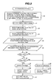
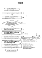
- An energy judgment process executed in the energy judgment processing unit 26 will be described in more detail with reference to Fig. 3.
- the energy judgment processing unit 26 receives the judgment information 78 corresponding to the set energy from the accelerator controller 22 (step 30).
- the judgment information 78 contains a reference value Rdes of the radial beam position x, an allowable range Rerr for the reference value Rdes, a reference value Fdes of the frequency of the RF voltage (i.e., the acceleration frequency), and an allowable range Ferr for the reference value Fdes at the end of the acceleration.
- the energy judgment processing unit 26 receives the energy check signal 75 outputted from the timing controller 25 (step 31).
- the energy judgment processing unit 26 After receiving the energy check signal 75, the energy judgment processing unit 26 receives the measured value Rmes of the radial beam position x from the beam signal processing unit 21 and the measured value Fmes of the acceleration frequency from the frequency counter 19 (steps 32 and 33).
- the measured values Rmes and Fmes represent respective values measured after the outputting of the energy check signal 75.
- Receiving the measured values Rmes and Fmes after the energy judgment processing unit 26 has received the energy check signal 75 means that the radial beam position x and the acceleration frequency are measured after the outputting of the energy check signal 75 from the timing controller 25.
- step 35 an absolute value of a deviation Fdev between the measured value Fmes and the reference value Fdes is calculated.
- Fdev [Fmes - Fdes
- Rdev > Rerr is satisfied.
- Fdev > Ferr is satisfied (step 37).
- an energy normal signal is outputted as an energy judgment signal 77 to the accelerator controller 22 and the gate switch 9 (step 39). The gate switch 9 is closed in response to the energy normal signal.
- the outputting of the energy normal signal means that the energy of the ion beam 14 after the end of the acceleration is matched with the set energy. If the determination result in step 36 or 37 is "Yes", it is determined that the energy of the ion beam 14 deviates from the set energy and is abnormal (step 40). Correspondingly, an energy abnormal signal is outputted as the energy judgment signal 77 to the accelerator controller 22 and the gate switch 9 (step 41). The outputting of the energy abnormal signal means that the energy of the ion beam 14 after the end of the acceleration deviates from the set energy.
- the gate switch 9 is closed when the energy normal signal is outputted, and it is opened when the energy abnormal signal is outputted.
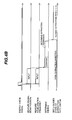
- Fig. 4B shows the foregoing steps of the energy determination process together in the form of a time-serial chart.
- the accelerator controller 22 In response to the energy normal signal or the energy abnormal signal, the accelerator controller 22 having received the energy judgment signal 77 monitors the state of the ion beam 14 being supplied to the irradiation apparatus 16.
- the gate switch 9 When the gate switch 9 is closed in response to the energy normal signal outputted from the energy judgment processing unit 26 and the extraction switch 8 is closed in response to the outputting of the extraction permit signal 76, the ion beam 14 is extracted from the synchrotron 3 and irradiated to the cancer in the body of the patient in a manner as described above.
- the gate switch 9 In the state of the gate switch 9 being opened in response to the energy abnormal signal outputted from the energy judgment processing unit 26, even when the extraction switch 8 is closed in response to the outputting of the extraction permit signal 76, the ion beam is not extracted from the synchrotron 3 because no RF signal is applied to the RF knockout electrode 6.
- an allowable range of energy variations is set (step 45). This allowable range is set to be, e.g., not larger than ⁇ 0.1% of the set energy when the ion beam is irradiated based on the ion beam scanning method. The allowable range of energy variations differs depending on the set energy and is decided as a setting parameter for the particle therapy system 1 beforehand. Then, an operation for adjustment of the ion beam is performed in the synchrotron 3 (step 46).
- the acceleration frequency is adjusted with respect to the bending magnetic field strength so that the ion beam 14 is accelerated to reach the set energy, and the amount of excitation for each of the magnets disposed in the synchrotron 3, the acceleration frequency, etc. are adjusted so that the ion beam can be extracted in a predetermined charge amount from the synchrotron 3.
- step 47 it is determined whether the ion beam can be extracted in the predetermined charge amount (step 47). If the determination result is "No", the adjustment operation in step 46 is performed again to adjust the amount of excitation for each of the magnets disposed in the synchrotron 3, the acceleration frequency, etc. If the determination result in step 47 is "Yes”, the ion beam is transported to the irradiation apparatus 16, and the range of the ion beam having passed through the irradiation apparatus 16 is measured by a dose meter, e.g., a water phantom, installed downstream of the irradiation apparatus 16 (step 48). Based on the measured result of the range, the energy of the ion beam accelerated and extracted from the synchrotron 3 is determined (step 49).
- a dose meter e.g., a water phantom
- the frequency of the RF voltage applied to the RF cavity 10 i.e., the acceleration frequency
- the reference values of both the acceleration frequency and the orbit position of the barycenter of the ion beam are given by respective values measured in the above measuring steps.
- respective allowable ranges for the reference values of the acceleration frequency and the radial beam position are calculated (step 51). Table data corresponding to one level of energy is prepared using the energy of the extracted ion beam which has been judged in step 49, the respective reference values of the acceleration frequency and the radial beam position which have been measured in step 50, and the respective allowable ranges for those reference values which have been calculated in step 51 (step 53).
- a set of operation control values for the synchrotron 3, the measured results of the ion beam energy, and the table data are correlated with one another, thereby preparing acceleration control pattern data for the synchrotron 3 (step 52).
- the above-described processing is repeatedly executed while changing the energy of the ion beam extracted from the synchrotron 3 to each of various levels, to thereby obtain the respective reference values of the acceleration frequency and the radial beam position, as well as the respective allowable ranges for those reference values corresponding to each different level of energy.
- the respective reference values of the acceleration frequency and the radial beam position, as well as the respective allowable ranges for those reference values, which have been obtained in the processing shown in Fig. 5, are used as the judgment information 78 in the process for determining the ion beam energy.
- the ion beam 14 at the level of the set energy can be irradiated to the patient, and the position in the patient body where the ion beam 14 reaches (i.e., the position where the Bragg peak is formed) can be prevented from deviating from the destination position of the ion beam set in the treatment plan (i.e., from the set destination position).
- the energy of the ion beam 14 can be confirmed after the end of acceleration of the ion beam 14, but before the irradiation of the ion beam 14 from the synchrotron 3. Further, since the gate switch 9 is opened when the energy of the ion beam 14 after the end of the acceleration differs from the set energy, the ion beam 14 having energy at a value different from the set energy can be prevented from being extracted from the synchrotron 3, namely it can be prevented from being irradiated to the patient. This remarkably increases safety of the particle therapy system 1. If the ion beam 14 having energy at a value different from the set energy is irradiated to the patient, the Bragg peak is formed in the position of normal cells other than the cancer, and the normal cells are severely damaged. In other words, this first embodiment is able to avoid damage of the normal cells, which could be caused by the ion beam 14 reaching the position deviated from the destination position.
- a particle therapy system 1A according to a second embodiment of the present invention will be described below with reference to Fig. 6.
- the particle therapy system 1A differs from the particle therapy system 1 of the first embodiment in using a magnetic field sensor 60, a bending magnetic field strength measuring unit 62, and an energy judgment processing unit 26A in place of the cavity voltage monitor 18, the frequency counter 19, and the energy judgment processing unit 26, respectively.
- the other construction of the particle therapy system 1A is the same as that of the particle therapy system 1.
- the magnetic field sensor 60 is installed on the bending magnet 5.
- the bending magnetic field strength measuring unit 62 connected to the magnetic field sensor 60 is connected to the energy judgment processing unit 26A.
- a practical example of the magnetic field sensor 60 is a sensor for detecting an absolute magnetic field, such as a Hall device, or a sensor for detecting an absolute magnetic field, such as a search coil (see Japanese Patent No. 3269437).
- This embodiment uses, as the magnetic field sensor 60, a Hall device for detecting an absolute magnetic field.
- a detected signal from the magnetic field sensor 60 is inputted to the bending magnetic field strength measuring unit 62.
- the bending magnetic field strength measuring unit 62 measures the bending magnetic field strength based on the detected signal, and then outputs a measured value of the bending magnetic field strength to the energy judgment processing unit 26A.
- the energy judgment processing unit 26A executes an energy determination process modified from the energy determination process shown in Fig. 3, to thereby determine whether the energy of the ion beam 14 orbiting within the synchrotron 3 at the end of the acceleration is matched with the set energy.
- the modified energy determination process differs from the energy determination process shown in Fig. 3 in replacing the reference value Fdes with a reference value Bdes of the bending magnetic field strength, the allowable range Ferr with an allowable range Berr for the reference value Bdes, and the measured value Fmes with the measured value Bmes.
- Judgment information 79 transmitted from the accelerator controller 22 to the energy judgment processing unit 26A contains the reference value Rdes and the allowable range Rerr, as well as the reference value Bdes of the bending magnetic field strength and the allowable range Berr for the reference value Bdes at the end of the acceleration.
- this second embodiment can provide the advantages obtainable with the first embodiment.
- an output voltage of a search coil represents a time-dependent change rate of the bending magnetic field strength.
- a particle therapy system 1B according to a third embodiment of the present invention will be described below with reference to Fig. 7.
- the particle therapy system 1B of this third embodiment differs from the particle therapy system 1 of the first embodiment in that the cavity voltage monitor 18 and the frequency counter 19 are omitted, and the energy judgment processing unit 26 is replaced with a radial beam position judgment unit 63, a frequency judgment unit 64, and a judgment result output unit 65.
- the other construction of the particle therapy system 1B is the same as that of the particle therapy system 1.
- the radial beam position judgment unit 63, the frequency judgment unit 64, and the judgment result output unit judgment result output unit 65 essentially constitute the energy judgment processing unit 26.
- the RF controller and the beam signal processing unit are constructed of a digital signal processing circuit using a DSP (Digital Signal Processor), etc. in many cases.
- This embodiment employs, instead of the RF controller 24 in the first embodiment, an RF controller 24A including a digital signal processing circuit using a DSP, and instead of the beam signal processing unit 21, a beam signal processing unit (radial beam position measuring device) 21A including a digital signal processing circuit using a DSP.
- the frequency judgment unit 64 is connected to the RF controller 24A.
- the radial beam position judgment unit 63 is connected to the beam signal processing unit 21A.
- a digital oscillator 11A is employed as the oscillator for generating the RF voltage applied to the RF cavity, whereby an RF signal is produced with high purity and high reproducibility. Further, the frequency of the RF signal outputted from the digital oscillator 11A is set with a digital value from the RF controller 24A and is outputted from the oscillator with high fidelity. Accordingly, with no need of utilizing any frequency counter, such as a spectrum analyzer, to measure the output signal from the cavity voltage monitor associated with the RF cavity, a similar result to that in the case of externally measuring the frequency can be obtained by confirming the frequency of the RF voltage set for the digital oscillator 11A.
- any frequency counter such as a spectrum analyzer
- the frequency judgment unit 64 executes the processing of steps 30, 31, 33, 35 and 37 in the energy determination process shown in Fig. 3.
- the frequency judgment unit 64 receives the reference value Fdes and the allowable range Ferr, i.e., judgment information 78A corresponding to the set energy, from the accelerator controller 22. Then, the frequency judgment unit 64 executes the processing of steps 31, 33, 35 and 37.
- the frequency judgment unit 64 receives the frequency set for the digital oscillator 11A, as the measured value Fmes, from the RF controller 24A.
- the radial beam position judgment unit 63 executes the processing of steps 30-32, 34 and 36 in the energy determination process shown in Fig. 3.
- step 30 the radial beam position judgment unit 63 receives the reference value Rdes and the allowable range Rerr, i.e., judgment information 78B corresponding to the set energy, from the accelerator controller 22. Then, the radial beam position judgment unit 63 executes the processing of steps 31, 32, 34 and 36.
- the judgment result output unit 65 receives judgment result 85 obtained in step 36 from the radial beam position judgment unit 63 and judgment result 84 obtained in step 37 from the frequency judgment unit 64. If both results of the judgment result 84, 85 represent "No", the judgment result output unit 65 executes the processing of steps 38, 39 shown in Fig. 3 and outputs, as the energy judgment signal 77, the energy normal signal to the accelerator controller 22 and the gate switch 9. If the judgment result 84 or the judgment result 85 represents "Yes", the judgment result output unit 65 executes the processing of steps 40, 41 shown in Fig. 3 and outputs, as the energy judgment signal 77, the energy abnormal signal to the accelerator controller 22 and the gate switch 9.
- This third embodiment can also provide the advantages obtainable with the first embodiment.
- a particle therapy system 1C according to a fourth embodiment of the present invention will be described below with reference to Fig. 8.
- the particle therapy system 1C of this fourth embodiment differs from the particle therapy system 1A of the second embodiment in that the energy judgment processing unit 26A is replaced with a radial beam position judgment unit 63, a bending magnetic field strength judgment unit 66, and a judgment result output unit 65.
- the other construction of the particle therapy system 1C is the same as that of the particle therapy system 1A.
- the radial beam position judgment unit 63, the bending magnetic field strength judgment unit 66, and the judgment result output unit 66 essentially constitute the energy judgment processing unit 26A.
- the bending magnetic field strength judgment unit 66 is connected to the bending magnetic field strength meter 62.
- the bending magnetic field strength judgment unit 66 executes the processing of steps 30, 31, 33, 35 and 37 in the modified energy determination process described in the second embodiment.
- the bending magnetic field strength judgment unit 66 receives the reference value Bdes and the allowable range Berr, i.e., judgment information 79A corresponding to the set energy, from the accelerator controller 22. Then, the bending magnetic field strength judgment unit 66 executes the processing of steps 31, 33, 35 and 37.
- the radial beam position judgment unit 63 executes the processing of steps 30-32, 34 and 36 in the modified energy determination process described in the second embodiment.
- step 30 the radial beam position judgment unit 63 receives the reference value Rdes and the allowable range Rerr, i.e., the judgment information 78B corresponding to the set energy, from the accelerator controller 22. Then, the radial beam position judgment unit 63 executes the processing of steps 31, 32, 34 and 36.
- the judgment result output unit 65 receives the judgment result 85 obtained in step 36 from the radial beam position judgment unit 63 and judgment result 86 obtained in step 37 from the bending magnetic field strength judgment unit 66. If both results of the judgment result 85, 86 represent "No", the judgment result output unit 65 executes the processing of steps 38, 39 and outputs, as the energy judgment signal 77, the energy normal signal to the accelerator controller 22 and the gate switch 9. If the judgment result 85 or the judgment result 86 represents "Yes", the judgment result output unit 65 executes the processing of steps 40, 41 and outputs, as the energy judgment signal 77, the energy abnormal signal to the accelerator controller 22 and the gate switch 9.
- This fourth embodiment can also provide the advantages obtainable with the second embodiment.
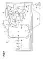
- a particle therapy system 1D according to a fifth embodiment of the present invention will be described below with reference to Fig. 9.
- the particle therapy system 1D of this fifth embodiment is constituted by adding, to the particle therapy system 1 of the first embodiment, a beam intensity judgment unit 67 and a gate switch (third on/off switch) 68 serving as a second safety device. Further, the particle therapy system 1D includes a beam signal processing unit 54. The other construction of the particle therapy system 1D is the same as that of the particle therapy system 1.
- the gate switch 68 is disposed between the RF knockout electrode 6 and the gate switch 9, and it is connected to them.
- the beam signal processing unit 54 is connected to the two sets of electrodes (i.e., the electrodes 68A, 68B and the electrodes 69A, 69B) of the beam position monitor 20.
- the beam intensity judgment unit 67 is connected to an envelope detector 55 (described later) of the beam signal processing unit 54, the accelerator controller 22, the timing controller 25, and the gate switch 68.
- the beam intensity judgment unit 67 is provided separately from the energy judgment processing unit 26.
- the strength of the ion beam orbiting within the synchrotron 3 can be measured as an average charge amount by envelope detection of signals outputted from the two sets of electrodes (i.e., the electrodes 68A, 68B and the electrodes 69A, 69B) of the beam position monitor 20.
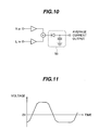
- the beam signal processing unit 54 includes the beam signal processing unit 21 (not shown in Fig. 9), which is used in the first embodiment, and the envelope detector 55 (see Fig. 10) for performing the envelope detection.
- the beam signal processing unit 21 and the envelope detector 55 are connected to the two sets of electrodes of the beam position monitor 20.
- the beam position monitor 20 outputs a signal having a voltage waveform shown in Fig. 11.
- Such a voltage waveform is provided as the sum of outputs from the two sets of electrodes and is inputted to both of the beam signal processing unit 21 and the envelope detector 55.
- the voltage waveform represents the form of the bunched ion beam 14 orbiting within the synchrotron 3. Because the average charge amount, i.e., the ion beam intensity, is detected as a DC component on the negative side of the bunched waveform, it can be obtained by adding respective signals (V R , V L ) outputted from the two sets of electrodes of the beam position monitor 20, and performing the envelope detection of a negative component of the added result in the envelope detector 55. A measured value Imes of the ion beam intensity obtained by the envelope detector 55 is inputted to the beam intensity judgment unit 67.
- the energy judgment processing unit 26 receives the measured value Rmes from the beam signal processing unit 21 and the measured value Fmes from the frequency counter 19. Then, the energy judgment processing unit 26 executes the determination process shown in Fig. 3, and outputs the energy normal signal or the energy abnormal signal to the accelerator controller 22 and the gate switch 9.
- a strength normal signal is outputted as an ion beam intensity determination signal 89 to the accelerator controller 22 and the gate switch 68.
- the gate switch 68 is closed in response to the strength normal signal.
- the outputting of the strength normal signal means that the energy of the ion beam 14 after the end of the acceleration is matched with the set energy. If the above determination result is "Yes”, this means that the strength of the ion beam 14 is in an abnormal state deviating from the set ion beam intensity. Therefore, a strength abnormal signal is outputted as the ion beam intensity determination signal 89 to the accelerator controller 22 and the gate switch 68.
- the gate switch 68 is closed when the strength normal signal is outputted, and it is opened when the strength abnormal signal is outputted. The outputting of the strength abnormal signal inhibits the application of the RF signal from the RF knockout electrode 6, to thereby stop the extraction of the ion beam from the synchrotron 3.
- This fifth embodiment can provide the advantages obtainable with the first embodiment.
- this fifth embodiment can provide the following advantages. Since the strength of the ion beam 14 orbiting within the synchrotron 3 can be measured in accordance with the output of the beam position monitor 20 disposed in the synchrotron 3 after the end of the acceleration, but before the extraction of the ion beam 14, the strength of the ion beam 14 irradiated to the patient can be confirmed in advance. Therefore, the ion beam 14 having the set ion beam intensity can be irradiated to the cancer (target area) in the patient body.
- the ion beam 14 when the ion beam 14 is irradiated to one layer at a deep position, the ion beam is also irradiated to another layer at a position shallower than that of the one layer. For that reason, it is required to reduce the strength of the ion beam irradiated to an area in the other layer at the shallower position, which overlies the one layer at the deep position.
- the beam intensity judgment unit 67, the gate switch 68, and the beam signal processing unit 54 used in this fifth embodiment are also applicable to any of the second to fourth embodiments described above.
- the beam signal processing unit 54 includes the beam signal processing unit 21A instead of the beam signal processing unit 21.
Landscapes
- Physics & Mathematics (AREA)
- Engineering & Computer Science (AREA)
- Plasma & Fusion (AREA)
- Spectroscopy & Molecular Physics (AREA)
- Radiation-Therapy Devices (AREA)
- Particle Accelerators (AREA)
Applications Claiming Priority (2)
| Application Number | Priority Date | Filing Date | Title |
|---|---|---|---|
| JP2003377672A JP3912364B2 (ja) | 2003-11-07 | 2003-11-07 | 粒子線治療装置 |
| JP2003377672 | 2003-11-07 |
Publications (3)
| Publication Number | Publication Date |
|---|---|
| EP1530410A2 true EP1530410A2 (de) | 2005-05-11 |
| EP1530410A3 EP1530410A3 (de) | 2009-11-04 |
| EP1530410B1 EP1530410B1 (de) | 2017-02-08 |
Family
ID=34431326
Family Applications (1)
| Application Number | Title | Priority Date | Filing Date |
|---|---|---|---|
| EP04026311.3A Expired - Lifetime EP1530410B1 (de) | 2003-11-07 | 2004-11-05 | Teilchen-Therapieanlage |
Country Status (3)
| Country | Link |
|---|---|
| US (1) | US7439528B2 (de) |
| EP (1) | EP1530410B1 (de) |
| JP (1) | JP3912364B2 (de) |
Cited By (2)
| Publication number | Priority date | Publication date | Assignee | Title |
|---|---|---|---|---|
| EP2141512A3 (de) * | 2008-06-27 | 2016-11-09 | Siemens Healthcare GmbH | Verfahren zur Energieüberprüfung eines Partikelstrahls, Vorrichtung zur Energieüberprüfung sowie Anlage hiermit |
| CN115445106A (zh) * | 2022-09-30 | 2022-12-09 | 兰州科近泰基新技术有限责任公司 | 离子治疗装置的束流能量监测方法及束流控制方法 |
Families Citing this family (131)
| Publication number | Priority date | Publication date | Assignee | Title |
|---|---|---|---|---|
| US7317192B2 (en) * | 2003-06-02 | 2008-01-08 | Fox Chase Cancer Center | High energy polyenergetic ion selection systems, ion beam therapy systems, and ion beam treatment centers |
| ES2720574T3 (es) | 2004-07-21 | 2019-07-23 | Mevion Medical Systems Inc | Generador de forma de onda de radio frecuencia programable para un sincrociclotrón |
| US9077022B2 (en) * | 2004-10-29 | 2015-07-07 | Medtronic, Inc. | Lithium-ion battery |
| EP1764132A1 (de) * | 2005-09-16 | 2007-03-21 | Siemens Aktiengesellschaft | Verfahren und Vorrichtung zur Einstellung eines Strahlpfades einer Partikeltherapieanlage |
| CN101361156B (zh) | 2005-11-18 | 2012-12-12 | 梅维昂医疗系统股份有限公司 | 用于实施放射治疗的设备 |
| US7530616B2 (en) * | 2006-05-19 | 2009-05-12 | Breya, Llc. | Mobile radiation therapy |
| US8657354B2 (en) * | 2006-05-19 | 2014-02-25 | Breya, Llc. | Mobile radiation therapy |
| US8459714B2 (en) * | 2006-05-19 | 2013-06-11 | Breya, Llc. | Mobile radiation therapy |
| JP4378396B2 (ja) * | 2007-06-22 | 2009-12-02 | 株式会社日立製作所 | 粒子線照射システム |
| US7947969B2 (en) * | 2007-06-27 | 2011-05-24 | Mitsubishi Electric Corporation | Stacked conformation radiotherapy system and particle beam therapy apparatus employing the same |
| US8581523B2 (en) | 2007-11-30 | 2013-11-12 | Mevion Medical Systems, Inc. | Interrupted particle source |
| US8933650B2 (en) | 2007-11-30 | 2015-01-13 | Mevion Medical Systems, Inc. | Matching a resonant frequency of a resonant cavity to a frequency of an input voltage |
| US9737733B2 (en) | 2008-05-22 | 2017-08-22 | W. Davis Lee | Charged particle state determination apparatus and method of use thereof |
| US9616252B2 (en) | 2008-05-22 | 2017-04-11 | Vladimir Balakin | Multi-field cancer therapy apparatus and method of use thereof |
| CN102119586B (zh) | 2008-05-22 | 2015-09-02 | 弗拉迪米尔·叶戈罗维奇·巴拉金 | 多场带电粒子癌症治疗方法和装置 |
| US8378311B2 (en) | 2008-05-22 | 2013-02-19 | Vladimir Balakin | Synchrotron power cycling apparatus and method of use thereof |
| US9579525B2 (en) * | 2008-05-22 | 2017-02-28 | Vladimir Balakin | Multi-axis charged particle cancer therapy method and apparatus |
| US8637833B2 (en) | 2008-05-22 | 2014-01-28 | Vladimir Balakin | Synchrotron power supply apparatus and method of use thereof |
| US10070831B2 (en) | 2008-05-22 | 2018-09-11 | James P. Bennett | Integrated cancer therapy—imaging apparatus and method of use thereof |
| US8642978B2 (en) | 2008-05-22 | 2014-02-04 | Vladimir Balakin | Charged particle cancer therapy dose distribution method and apparatus |
| US9937362B2 (en) | 2008-05-22 | 2018-04-10 | W. Davis Lee | Dynamic energy control of a charged particle imaging/treatment apparatus and method of use thereof |
| EP2283713B1 (de) | 2008-05-22 | 2018-03-28 | Vladimir Yegorovich Balakin | Vorrichtung zur krebstherapie mit geladenen teilchen mit mehreren achsen |
| US8198607B2 (en) | 2008-05-22 | 2012-06-12 | Vladimir Balakin | Tandem accelerator method and apparatus used in conjunction with a charged particle cancer therapy system |
| US8710462B2 (en) | 2008-05-22 | 2014-04-29 | Vladimir Balakin | Charged particle cancer therapy beam path control method and apparatus |
| US9044600B2 (en) | 2008-05-22 | 2015-06-02 | Vladimir Balakin | Proton tomography apparatus and method of operation therefor |
| US8089054B2 (en) | 2008-05-22 | 2012-01-03 | Vladimir Balakin | Charged particle beam acceleration and extraction method and apparatus used in conjunction with a charged particle cancer therapy system |
| US8975600B2 (en) | 2008-05-22 | 2015-03-10 | Vladimir Balakin | Treatment delivery control system and method of operation thereof |
| US10684380B2 (en) | 2008-05-22 | 2020-06-16 | W. Davis Lee | Multiple scintillation detector array imaging apparatus and method of use thereof |
| US10143854B2 (en) | 2008-05-22 | 2018-12-04 | Susan L. Michaud | Dual rotation charged particle imaging / treatment apparatus and method of use thereof |
| US8129694B2 (en) | 2008-05-22 | 2012-03-06 | Vladimir Balakin | Negative ion beam source vacuum method and apparatus used in conjunction with a charged particle cancer therapy system |
| US9498649B2 (en) | 2008-05-22 | 2016-11-22 | Vladimir Balakin | Charged particle cancer therapy patient constraint apparatus and method of use thereof |
| US9855444B2 (en) | 2008-05-22 | 2018-01-02 | Scott Penfold | X-ray detector for proton transit detection apparatus and method of use thereof |
| US9168392B1 (en) | 2008-05-22 | 2015-10-27 | Vladimir Balakin | Charged particle cancer therapy system X-ray apparatus and method of use thereof |
| US8129699B2 (en) | 2008-05-22 | 2012-03-06 | Vladimir Balakin | Multi-field charged particle cancer therapy method and apparatus coordinated with patient respiration |
| US9981147B2 (en) | 2008-05-22 | 2018-05-29 | W. Davis Lee | Ion beam extraction apparatus and method of use thereof |
| US8969834B2 (en) | 2008-05-22 | 2015-03-03 | Vladimir Balakin | Charged particle therapy patient constraint apparatus and method of use thereof |
| US8373145B2 (en) | 2008-05-22 | 2013-02-12 | Vladimir Balakin | Charged particle cancer therapy system magnet control method and apparatus |
| US10092776B2 (en) | 2008-05-22 | 2018-10-09 | Susan L. Michaud | Integrated translation/rotation charged particle imaging/treatment apparatus and method of use thereof |
| US8093564B2 (en) | 2008-05-22 | 2012-01-10 | Vladimir Balakin | Ion beam focusing lens method and apparatus used in conjunction with a charged particle cancer therapy system |
| US7939809B2 (en) | 2008-05-22 | 2011-05-10 | Vladimir Balakin | Charged particle beam extraction method and apparatus used in conjunction with a charged particle cancer therapy system |
| US8144832B2 (en) | 2008-05-22 | 2012-03-27 | Vladimir Balakin | X-ray tomography method and apparatus used in conjunction with a charged particle cancer therapy system |
| US8519365B2 (en) | 2008-05-22 | 2013-08-27 | Vladimir Balakin | Charged particle cancer therapy imaging method and apparatus |
| US9910166B2 (en) | 2008-05-22 | 2018-03-06 | Stephen L. Spotts | Redundant charged particle state determination apparatus and method of use thereof |
| US9782140B2 (en) | 2008-05-22 | 2017-10-10 | Susan L. Michaud | Hybrid charged particle / X-ray-imaging / treatment apparatus and method of use thereof |
| US8896239B2 (en) | 2008-05-22 | 2014-11-25 | Vladimir Yegorovich Balakin | Charged particle beam injection method and apparatus used in conjunction with a charged particle cancer therapy system |
| US9056199B2 (en) | 2008-05-22 | 2015-06-16 | Vladimir Balakin | Charged particle treatment, rapid patient positioning apparatus and method of use thereof |
| US9155911B1 (en) | 2008-05-22 | 2015-10-13 | Vladimir Balakin | Ion source method and apparatus used in conjunction with a charged particle cancer therapy system |
| US8309941B2 (en) | 2008-05-22 | 2012-11-13 | Vladimir Balakin | Charged particle cancer therapy and patient breath monitoring method and apparatus |
| US8598543B2 (en) * | 2008-05-22 | 2013-12-03 | Vladimir Balakin | Multi-axis/multi-field charged particle cancer therapy method and apparatus |
| US8368038B2 (en) | 2008-05-22 | 2013-02-05 | Vladimir Balakin | Method and apparatus for intensity control of a charged particle beam extracted from a synchrotron |
| US9682254B2 (en) | 2008-05-22 | 2017-06-20 | Vladimir Balakin | Cancer surface searing apparatus and method of use thereof |
| US8907309B2 (en) | 2009-04-17 | 2014-12-09 | Stephen L. Spotts | Treatment delivery control system and method of operation thereof |
| US8436327B2 (en) * | 2008-05-22 | 2013-05-07 | Vladimir Balakin | Multi-field charged particle cancer therapy method and apparatus |
| WO2009142545A2 (en) | 2008-05-22 | 2009-11-26 | Vladimir Yegorovich Balakin | Charged particle cancer therapy patient positioning method and apparatus |
| US9058910B2 (en) | 2008-05-22 | 2015-06-16 | Vladimir Yegorovich Balakin | Charged particle beam acceleration method and apparatus as part of a charged particle cancer therapy system |
| US10029122B2 (en) | 2008-05-22 | 2018-07-24 | Susan L. Michaud | Charged particle—patient motion control system apparatus and method of use thereof |
| US8378321B2 (en) | 2008-05-22 | 2013-02-19 | Vladimir Balakin | Charged particle cancer therapy and patient positioning method and apparatus |
| WO2009142544A2 (en) | 2008-05-22 | 2009-11-26 | Vladimir Yegorovich Balakin | Charged particle cancer therapy beam path control method and apparatus |
| US8718231B2 (en) | 2008-05-22 | 2014-05-06 | Vladimir Balakin | X-ray tomography method and apparatus used in conjunction with a charged particle cancer therapy system |
| US8374314B2 (en) | 2008-05-22 | 2013-02-12 | Vladimir Balakin | Synchronized X-ray / breathing method and apparatus used in conjunction with a charged particle cancer therapy system |
| US8399866B2 (en) | 2008-05-22 | 2013-03-19 | Vladimir Balakin | Charged particle extraction apparatus and method of use thereof |
| US8288742B2 (en) | 2008-05-22 | 2012-10-16 | Vladimir Balakin | Charged particle cancer therapy patient positioning method and apparatus |
| US9737734B2 (en) | 2008-05-22 | 2017-08-22 | Susan L. Michaud | Charged particle translation slide control apparatus and method of use thereof |
| US8624528B2 (en) | 2008-05-22 | 2014-01-07 | Vladimir Balakin | Method and apparatus coordinating synchrotron acceleration periods with patient respiration periods |
| US8178859B2 (en) | 2008-05-22 | 2012-05-15 | Vladimir Balakin | Proton beam positioning verification method and apparatus used in conjunction with a charged particle cancer therapy system |
| CA2725315C (en) | 2008-05-22 | 2015-06-30 | Vladimir Yegorovich Balakin | X-ray method and apparatus used in conjunction with a charged particle cancer therapy system |
| US9177751B2 (en) | 2008-05-22 | 2015-11-03 | Vladimir Balakin | Carbon ion beam injector apparatus and method of use thereof |
| US10548551B2 (en) | 2008-05-22 | 2020-02-04 | W. Davis Lee | Depth resolved scintillation detector array imaging apparatus and method of use thereof |
| US9974978B2 (en) | 2008-05-22 | 2018-05-22 | W. Davis Lee | Scintillation array apparatus and method of use thereof |
| US9744380B2 (en) | 2008-05-22 | 2017-08-29 | Susan L. Michaud | Patient specific beam control assembly of a cancer therapy apparatus and method of use thereof |
| US9095040B2 (en) | 2008-05-22 | 2015-07-28 | Vladimir Balakin | Charged particle beam acceleration and extraction method and apparatus used in conjunction with a charged particle cancer therapy system |
| US9737272B2 (en) | 2008-05-22 | 2017-08-22 | W. Davis Lee | Charged particle cancer therapy beam state determination apparatus and method of use thereof |
| WO2009142550A2 (en) | 2008-05-22 | 2009-11-26 | Vladimir Yegorovich Balakin | Charged particle beam extraction method and apparatus used in conjunction with a charged particle cancer therapy system |
| US8373146B2 (en) | 2008-05-22 | 2013-02-12 | Vladimir Balakin | RF accelerator method and apparatus used in conjunction with a charged particle cancer therapy system |
| US8373143B2 (en) | 2008-05-22 | 2013-02-12 | Vladimir Balakin | Patient immobilization and repositioning method and apparatus used in conjunction with charged particle cancer therapy |
| US8188688B2 (en) | 2008-05-22 | 2012-05-29 | Vladimir Balakin | Magnetic field control method and apparatus used in conjunction with a charged particle cancer therapy system |
| US8569717B2 (en) * | 2008-05-22 | 2013-10-29 | Vladimir Balakin | Intensity modulated three-dimensional radiation scanning method and apparatus |
| JP4691583B2 (ja) * | 2008-07-02 | 2011-06-01 | 株式会社日立製作所 | 荷電粒子ビーム照射システムおよび荷電粒子ビーム出射方法 |
| US8627822B2 (en) | 2008-07-14 | 2014-01-14 | Vladimir Balakin | Semi-vertical positioning method and apparatus used in conjunction with a charged particle cancer therapy system |
| US8625739B2 (en) | 2008-07-14 | 2014-01-07 | Vladimir Balakin | Charged particle cancer therapy x-ray method and apparatus |
| US8229072B2 (en) * | 2008-07-14 | 2012-07-24 | Vladimir Balakin | Elongated lifetime X-ray method and apparatus used in conjunction with a charged particle cancer therapy system |
| JP5058932B2 (ja) * | 2008-09-30 | 2012-10-24 | 株式会社日立製作所 | 粒子線治療システム及び粒子線治療システムにおける荷電粒子ビームのエネルギー確認方法 |
| SG173879A1 (en) | 2009-03-04 | 2011-10-28 | Protom Aozt | Multi-field charged particle cancer therapy method and apparatus |
| JP5682967B2 (ja) * | 2009-08-11 | 2015-03-11 | 国立大学法人群馬大学 | パルス電圧を用いた荷電粒子ビームの取り出し方法および加速器 |
| JP4499185B1 (ja) * | 2009-08-27 | 2010-07-07 | 三菱電機株式会社 | 粒子線照射装置及び粒子線治療装置 |
| US9737731B2 (en) | 2010-04-16 | 2017-08-22 | Vladimir Balakin | Synchrotron energy control apparatus and method of use thereof |
| US10188877B2 (en) | 2010-04-16 | 2019-01-29 | W. Davis Lee | Fiducial marker/cancer imaging and treatment apparatus and method of use thereof |
| US10349906B2 (en) | 2010-04-16 | 2019-07-16 | James P. Bennett | Multiplexed proton tomography imaging apparatus and method of use thereof |
| US10589128B2 (en) | 2010-04-16 | 2020-03-17 | Susan L. Michaud | Treatment beam path verification in a cancer therapy apparatus and method of use thereof |
| US10556126B2 (en) | 2010-04-16 | 2020-02-11 | Mark R. Amato | Automated radiation treatment plan development apparatus and method of use thereof |
| US11648420B2 (en) | 2010-04-16 | 2023-05-16 | Vladimir Balakin | Imaging assisted integrated tomography—cancer treatment apparatus and method of use thereof |
| US10518109B2 (en) | 2010-04-16 | 2019-12-31 | Jillian Reno | Transformable charged particle beam path cancer therapy apparatus and method of use thereof |
| US10086214B2 (en) | 2010-04-16 | 2018-10-02 | Vladimir Balakin | Integrated tomography—cancer treatment apparatus and method of use thereof |
| US10751551B2 (en) | 2010-04-16 | 2020-08-25 | James P. Bennett | Integrated imaging-cancer treatment apparatus and method of use thereof |
| US10625097B2 (en) | 2010-04-16 | 2020-04-21 | Jillian Reno | Semi-automated cancer therapy treatment apparatus and method of use thereof |
| US10376717B2 (en) | 2010-04-16 | 2019-08-13 | James P. Bennett | Intervening object compensating automated radiation treatment plan development apparatus and method of use thereof |
| US10555710B2 (en) | 2010-04-16 | 2020-02-11 | James P. Bennett | Simultaneous multi-axes imaging apparatus and method of use thereof |
| US10638988B2 (en) | 2010-04-16 | 2020-05-05 | Scott Penfold | Simultaneous/single patient position X-ray and proton imaging apparatus and method of use thereof |
| US10179250B2 (en) | 2010-04-16 | 2019-01-15 | Nick Ruebel | Auto-updated and implemented radiation treatment plan apparatus and method of use thereof |
| US9265970B2 (en) * | 2011-03-02 | 2016-02-23 | Mitsubishi Electric Corporation | Particle beam irradiation system |
| US8963112B1 (en) | 2011-05-25 | 2015-02-24 | Vladimir Balakin | Charged particle cancer therapy patient positioning method and apparatus |
| US20140014849A1 (en) * | 2012-07-11 | 2014-01-16 | Procure Treatment Centers, Inc. | Permanent Magnet Beam Transport System for Proton Radiation Therapy |
| CN104813747B (zh) | 2012-09-28 | 2018-02-02 | 梅维昂医疗系统股份有限公司 | 使用磁场颤振聚焦粒子束 |
| WO2014052721A1 (en) | 2012-09-28 | 2014-04-03 | Mevion Medical Systems, Inc. | Control system for a particle accelerator |
| US10254739B2 (en) | 2012-09-28 | 2019-04-09 | Mevion Medical Systems, Inc. | Coil positioning system |
| EP2901821B1 (de) | 2012-09-28 | 2020-07-08 | Mevion Medical Systems, Inc. | Magnetfeldregenerator |
| US9185789B2 (en) | 2012-09-28 | 2015-11-10 | Mevion Medical Systems, Inc. | Magnetic shims to alter magnetic fields |
| US9723705B2 (en) | 2012-09-28 | 2017-08-01 | Mevion Medical Systems, Inc. | Controlling intensity of a particle beam |
| EP2900326B1 (de) | 2012-09-28 | 2019-05-01 | Mevion Medical Systems, Inc. | Steuerung einer partikeltherapie |
| US9301384B2 (en) | 2012-09-28 | 2016-03-29 | Mevion Medical Systems, Inc. | Adjusting energy of a particle beam |
| CN104813748B (zh) | 2012-09-28 | 2019-07-09 | 梅维昂医疗系统股份有限公司 | 聚焦粒子束 |
| US8933651B2 (en) | 2012-11-16 | 2015-01-13 | Vladimir Balakin | Charged particle accelerator magnet apparatus and method of use thereof |
| US8791656B1 (en) | 2013-05-31 | 2014-07-29 | Mevion Medical Systems, Inc. | Active return system |
| US9730308B2 (en) | 2013-06-12 | 2017-08-08 | Mevion Medical Systems, Inc. | Particle accelerator that produces charged particles having variable energies |
| CN105764567B (zh) | 2013-09-27 | 2019-08-09 | 梅维昂医疗系统股份有限公司 | 粒子束扫描 |
| US10675487B2 (en) | 2013-12-20 | 2020-06-09 | Mevion Medical Systems, Inc. | Energy degrader enabling high-speed energy switching |
| US9962560B2 (en) | 2013-12-20 | 2018-05-08 | Mevion Medical Systems, Inc. | Collimator and energy degrader |
| US9661736B2 (en) | 2014-02-20 | 2017-05-23 | Mevion Medical Systems, Inc. | Scanning system for a particle therapy system |
| US9950194B2 (en) | 2014-09-09 | 2018-04-24 | Mevion Medical Systems, Inc. | Patient positioning system |
| US10786689B2 (en) | 2015-11-10 | 2020-09-29 | Mevion Medical Systems, Inc. | Adaptive aperture |
| US9907981B2 (en) | 2016-03-07 | 2018-03-06 | Susan L. Michaud | Charged particle translation slide control apparatus and method of use thereof |
| US10879028B2 (en) * | 2016-04-14 | 2020-12-29 | Varian Medical Systems, Inc. | Beam position monitors for medical radiation machines |
| US10037863B2 (en) | 2016-05-27 | 2018-07-31 | Mark R. Amato | Continuous ion beam kinetic energy dissipater apparatus and method of use thereof |
| CN109803723B (zh) | 2016-07-08 | 2021-05-14 | 迈胜医疗设备有限公司 | 一种粒子疗法系统 |
| WO2018065195A1 (en) * | 2016-10-05 | 2018-04-12 | Asml Netherlands B.V. | Electron beam transport system |
| US11103730B2 (en) | 2017-02-23 | 2021-08-31 | Mevion Medical Systems, Inc. | Automated treatment in particle therapy |
| JP6936988B2 (ja) * | 2017-05-01 | 2021-09-22 | 東芝エネルギーシステムズ株式会社 | 加速器制御装置、加速器制御方法、および粒子線治療装置 |
| CN111093767B (zh) | 2017-06-30 | 2022-08-23 | 美国迈胜医疗系统有限公司 | 使用线性电动机而被控制的可配置准直仪 |
| JP7002952B2 (ja) * | 2018-01-29 | 2022-01-20 | 株式会社日立製作所 | 円形加速器、円形加速器を備えた粒子線治療システム、及び円形加速器の運転方法 |
| WO2020185543A1 (en) | 2019-03-08 | 2020-09-17 | Mevion Medical Systems, Inc. | Collimator and energy degrader for a particle therapy system |
| JP7430044B2 (ja) * | 2019-09-17 | 2024-02-09 | 住友重機械工業株式会社 | 放射線治療装置 |
Citations (2)
| Publication number | Priority date | Publication date | Assignee | Title |
|---|---|---|---|---|
| EP1073318A2 (de) | 1999-07-29 | 2001-01-31 | Hitachi, Ltd. | Verfahren und Vorrichtung zum Kontrollieren eines Ringbeschleunigers |
| JP2002151300A (ja) | 2000-11-09 | 2002-05-24 | Hitachi Ltd | チューン表示装置及びそれを有する円形加速器システム |
Family Cites Families (15)
| Publication number | Priority date | Publication date | Assignee | Title |
|---|---|---|---|---|
| JPH0732079B2 (ja) * | 1986-02-26 | 1995-04-10 | 株式会社日立製作所 | 電子ビ−ム安定化法 |
| JPH0676999A (ja) | 1992-08-31 | 1994-03-18 | Mitsubishi Electric Corp | ビーム位置モニタ及びビーム位置測定方法 |
| US5459393A (en) * | 1991-10-04 | 1995-10-17 | Mitsubishi Denki Kabushiki Kaisha | Beam position monitor and beam position detecting method |
| US5698954A (en) * | 1993-09-20 | 1997-12-16 | Hitachi, Ltd. | Automatically operated accelerator using obtained operating patterns |
| JP3307059B2 (ja) * | 1994-03-17 | 2002-07-24 | 株式会社日立製作所 | 加速器及び医療用装置並びに出射方法 |
| JPH08148298A (ja) | 1994-11-17 | 1996-06-07 | Hitachi Ltd | 加速器及びその運転方法 |
| JP3435926B2 (ja) | 1995-09-20 | 2003-08-11 | 株式会社日立製作所 | 円形加速器 |
| JP3518270B2 (ja) | 1996-08-30 | 2004-04-12 | 株式会社日立製作所 | 荷電粒子ビーム装置 |
| DE69729151T2 (de) * | 1996-08-30 | 2005-05-04 | Hitachi, Ltd. | Vorrichtung für einen geladenen Teilchenstrahl |
| JPH10294200A (ja) | 1997-04-18 | 1998-11-04 | Toshiba Corp | 加速器の制御装置 |
| JP3203211B2 (ja) * | 1997-08-11 | 2001-08-27 | 住友重機械工業株式会社 | 水ファントム型線量分布測定装置及び放射線治療装置 |
| JP2001085200A (ja) * | 1999-09-14 | 2001-03-30 | Hitachi Ltd | 加速器システム |
| JP2002217000A (ja) | 2001-01-19 | 2002-08-02 | Hitachi Ltd | ビーム位置モニタおよびこれを用いたシンクロトロン |
| JP2002367800A (ja) | 2001-06-05 | 2002-12-20 | Hitachi Ltd | 高周波加速装置及び円形加速器 |
| JP4114590B2 (ja) * | 2003-10-24 | 2008-07-09 | 株式会社日立製作所 | 粒子線治療装置 |
-
2003
- 2003-11-07 JP JP2003377672A patent/JP3912364B2/ja not_active Expired - Lifetime
-
2004
- 2004-11-05 US US10/981,505 patent/US7439528B2/en not_active Expired - Lifetime
- 2004-11-05 EP EP04026311.3A patent/EP1530410B1/de not_active Expired - Lifetime
Patent Citations (2)
| Publication number | Priority date | Publication date | Assignee | Title |
|---|---|---|---|---|
| EP1073318A2 (de) | 1999-07-29 | 2001-01-31 | Hitachi, Ltd. | Verfahren und Vorrichtung zum Kontrollieren eines Ringbeschleunigers |
| JP2002151300A (ja) | 2000-11-09 | 2002-05-24 | Hitachi Ltd | チューン表示装置及びそれを有する円形加速器システム |
Non-Patent Citations (2)
| Title |
|---|
| "DATABASE", accession no. 002-476916 |
| CHU W T; LUDEWIGHT B A; RENNER T R: "REVIEW OF SCIENTIFIC INSTRUMENTS", vol. 64, 1 August 1993, AIP, article "Instrumentation for treatment of cancer using proton and light-ion beams", pages: 2055 - 2122 |
Cited By (2)
| Publication number | Priority date | Publication date | Assignee | Title |
|---|---|---|---|---|
| EP2141512A3 (de) * | 2008-06-27 | 2016-11-09 | Siemens Healthcare GmbH | Verfahren zur Energieüberprüfung eines Partikelstrahls, Vorrichtung zur Energieüberprüfung sowie Anlage hiermit |
| CN115445106A (zh) * | 2022-09-30 | 2022-12-09 | 兰州科近泰基新技术有限责任公司 | 离子治疗装置的束流能量监测方法及束流控制方法 |
Also Published As
| Publication number | Publication date |
|---|---|
| US20050099145A1 (en) | 2005-05-12 |
| EP1530410B1 (de) | 2017-02-08 |
| US7439528B2 (en) | 2008-10-21 |
| JP3912364B2 (ja) | 2007-05-09 |
| JP2005142034A (ja) | 2005-06-02 |
| EP1530410A3 (de) | 2009-11-04 |
Similar Documents
| Publication | Publication Date | Title |
|---|---|---|
| US7439528B2 (en) | Particle therapy system and method | |
| US8253113B2 (en) | Charged particle beam irradiation system and charged particle beam extraction method | |
| US7982198B2 (en) | Particle beam irradiation system | |
| JP5597162B2 (ja) | 円形加速器、および円形加速器の運転方法 | |
| US7919765B2 (en) | Non-continuous particle beam irradiation method and apparatus | |
| EP2283705B1 (de) | Vorrichtung zur extraktion eines strahls geladener teilchen zur verwendung in verbindung mit einem krebstherapiesystem mit geladenen teilchen | |
| US6580084B1 (en) | Accelerator system | |
| JP5002612B2 (ja) | 荷電粒子ビーム照射装置 | |
| US9860969B2 (en) | Radio frequency voltage control system in synchrotron accelerating cavity | |
| EP2809133B1 (de) | Beschleuniger für geladene teilchen und teilchenstrahl-therapiesystem | |
| Iwata et al. | Performance of a compact injector for heavy-ion medical accelerators | |
| JP5159688B2 (ja) | 粒子線治療システム | |
| JP2011198748A (ja) | 荷電粒子ビーム照射システムおよび円形加速器の運転方法 | |
| JP3818227B2 (ja) | イオン源 | |
| EP0994638A1 (de) | Verfahren zur Ejektion eines Ladungsträgerstrahls und Vorrichtung dazu | |
| JP2008272139A (ja) | 荷電粒子ビーム照射システム及び荷電粒子ビーム出射方法 | |
| JP6537067B2 (ja) | 粒子線照射装置およびその制御方法 | |
| JP2006210354A (ja) | 粒子線治療装置 | |
| Dolinskii et al. | The Synchrotron of the dedicated Ion beam Facility for Cancer Therapy, proposed for the clinic in Heidelberg' | |
| JP3894215B2 (ja) | 荷電粒子ビームの出射方法及び粒子線照射システム | |
| JP3837957B2 (ja) | 荷電粒子ビーム照射方法及び装置 | |
| JP4650382B2 (ja) | 荷電粒子ビーム加速器及びその荷電粒子ビーム加速器を用いた粒子線照射システム | |
| JP3993338B2 (ja) | 粒子線照射装置 | |
| Schippers et al. | Beam intensity stability of a 250 MeV SC cyclotron equipped with an internal cold-cathode ion source | |
| JP5548571B2 (ja) | 粒子線照射システム |
Legal Events
| Date | Code | Title | Description |
|---|---|---|---|
| PUAI | Public reference made under article 153(3) epc to a published international application that has entered the european phase |
Free format text: ORIGINAL CODE: 0009012 |
|
| AK | Designated contracting states |
Kind code of ref document: A2 Designated state(s): AT BE BG CH CY CZ DE DK EE ES FI FR GB GR HU IE IS IT LI LU MC NL PL PT RO SE SI SK TR |
|
| AX | Request for extension of the european patent |
Extension state: AL HR LT LV MK YU |
|
| 17P | Request for examination filed |
Effective date: 20060331 |
|
| PUAL | Search report despatched |
Free format text: ORIGINAL CODE: 0009013 |
|
| AK | Designated contracting states |
Kind code of ref document: A3 Designated state(s): AT BE BG CH CY CZ DE DK EE ES FI FR GB GR HU IE IS IT LI LU MC NL PL PT RO SE SI SK TR |
|
| AX | Request for extension of the european patent |
Extension state: AL HR LT LV MK YU |
|
| AKX | Designation fees paid |
Designated state(s): DE FR GB IT SE |
|
| 17Q | First examination report despatched |
Effective date: 20131002 |
|
| REG | Reference to a national code |
Ref country code: DE Ref legal event code: R079 Ref document number: 602004050754 Country of ref document: DE Free format text: PREVIOUS MAIN CLASS: H05H0007060000 Ipc: H05H0013040000 |
|
| RIC1 | Information provided on ipc code assigned before grant |
Ipc: H05H 13/04 20060101AFI20151109BHEP Ipc: H05H 7/00 20060101ALI20151109BHEP |
|
| GRAP | Despatch of communication of intention to grant a patent |
Free format text: ORIGINAL CODE: EPIDOSNIGR1 |
|
| INTG | Intention to grant announced |
Effective date: 20160812 |
|
| STAA | Information on the status of an ep patent application or granted ep patent |
Free format text: STATUS: GRANT OF PATENT IS INTENDED |
|
| GRAS | Grant fee paid |
Free format text: ORIGINAL CODE: EPIDOSNIGR3 |
|
| GRAA | (expected) grant |
Free format text: ORIGINAL CODE: 0009210 |
|
| STAA | Information on the status of an ep patent application or granted ep patent |
Free format text: STATUS: THE PATENT HAS BEEN GRANTED |
|
| AK | Designated contracting states |
Kind code of ref document: B1 Designated state(s): DE FR GB IT SE |
|
| REG | Reference to a national code |
Ref country code: GB Ref legal event code: FG4D |
|
| REG | Reference to a national code |
Ref country code: DE Ref legal event code: R096 Ref document number: 602004050754 Country of ref document: DE |
|
| PG25 | Lapsed in a contracting state [announced via postgrant information from national office to epo] |
Ref country code: SE Free format text: LAPSE BECAUSE OF FAILURE TO SUBMIT A TRANSLATION OF THE DESCRIPTION OR TO PAY THE FEE WITHIN THE PRESCRIBED TIME-LIMIT Effective date: 20170208 |
|
| PG25 | Lapsed in a contracting state [announced via postgrant information from national office to epo] |
Ref country code: IT Free format text: LAPSE BECAUSE OF FAILURE TO SUBMIT A TRANSLATION OF THE DESCRIPTION OR TO PAY THE FEE WITHIN THE PRESCRIBED TIME-LIMIT Effective date: 20170208 |
|
| REG | Reference to a national code |
Ref country code: DE Ref legal event code: R097 Ref document number: 602004050754 Country of ref document: DE |
|
| REG | Reference to a national code |
Ref country code: FR Ref legal event code: PLFP Year of fee payment: 14 |
|
| PLBE | No opposition filed within time limit |
Free format text: ORIGINAL CODE: 0009261 |
|
| STAA | Information on the status of an ep patent application or granted ep patent |
Free format text: STATUS: NO OPPOSITION FILED WITHIN TIME LIMIT |
|
| 26N | No opposition filed |
Effective date: 20171109 |
|
| REG | Reference to a national code |
Ref country code: FR Ref legal event code: PLFP Year of fee payment: 15 |
|
| PGFP | Annual fee paid to national office [announced via postgrant information from national office to epo] |
Ref country code: GB Payment date: 20220930 Year of fee payment: 19 |
|
| PGFP | Annual fee paid to national office [announced via postgrant information from national office to epo] |
Ref country code: FR Payment date: 20221010 Year of fee payment: 19 |
|
| PGFP | Annual fee paid to national office [announced via postgrant information from national office to epo] |
Ref country code: DE Payment date: 20220930 Year of fee payment: 19 |
|
| REG | Reference to a national code |
Ref country code: DE Ref legal event code: R119 Ref document number: 602004050754 Country of ref document: DE |
|
| GBPC | Gb: european patent ceased through non-payment of renewal fee |
Effective date: 20231105 |
|
| PG25 | Lapsed in a contracting state [announced via postgrant information from national office to epo] |
Ref country code: DE Free format text: LAPSE BECAUSE OF NON-PAYMENT OF DUE FEES Effective date: 20240601 |
|
| PG25 | Lapsed in a contracting state [announced via postgrant information from national office to epo] |
Ref country code: GB Free format text: LAPSE BECAUSE OF NON-PAYMENT OF DUE FEES Effective date: 20231105 |
|
| PG25 | Lapsed in a contracting state [announced via postgrant information from national office to epo] |
Ref country code: FR Free format text: LAPSE BECAUSE OF NON-PAYMENT OF DUE FEES Effective date: 20231130 |
|
| PG25 | Lapsed in a contracting state [announced via postgrant information from national office to epo] |
Ref country code: GB Free format text: LAPSE BECAUSE OF NON-PAYMENT OF DUE FEES Effective date: 20231105 Ref country code: FR Free format text: LAPSE BECAUSE OF NON-PAYMENT OF DUE FEES Effective date: 20231130 Ref country code: DE Free format text: LAPSE BECAUSE OF NON-PAYMENT OF DUE FEES Effective date: 20240601 |