EP1530295A1 - Verfahren zur Analog-Digital-Wandlung und Analog-Digital-Wandler - Google Patents
Verfahren zur Analog-Digital-Wandlung und Analog-Digital-Wandler Download PDFInfo
- Publication number
- EP1530295A1 EP1530295A1 EP03025666A EP03025666A EP1530295A1 EP 1530295 A1 EP1530295 A1 EP 1530295A1 EP 03025666 A EP03025666 A EP 03025666A EP 03025666 A EP03025666 A EP 03025666A EP 1530295 A1 EP1530295 A1 EP 1530295A1
- Authority
- EP
- European Patent Office
- Prior art keywords
- analog
- signal
- level
- reference level
- signals
- Prior art date
- Legal status (The legal status is an assumption and is not a legal conclusion. Google has not performed a legal analysis and makes no representation as to the accuracy of the status listed.)
- Granted
Links
- 238000000034 method Methods 0.000 title claims abstract description 64
- 238000006243 chemical reaction Methods 0.000 title claims description 26
- 238000011156 evaluation Methods 0.000 claims description 63
- 238000001514 detection method Methods 0.000 claims description 17
- 230000015572 biosynthetic process Effects 0.000 claims description 11
- 230000002829 reductive effect Effects 0.000 claims description 9
- 238000010586 diagram Methods 0.000 description 5
- 238000012545 processing Methods 0.000 description 5
- 230000001419 dependent effect Effects 0.000 description 3
- 238000005303 weighing Methods 0.000 description 3
- 230000000052 comparative effect Effects 0.000 description 2
- 125000004122 cyclic group Chemical group 0.000 description 2
- 230000003247 decreasing effect Effects 0.000 description 2
- 238000011161 development Methods 0.000 description 2
- 230000018109 developmental process Effects 0.000 description 2
- 239000007787 solid Substances 0.000 description 2
- 230000001133 acceleration Effects 0.000 description 1
- 230000005540 biological transmission Effects 0.000 description 1
- 238000010276 construction Methods 0.000 description 1
- 238000013461 design Methods 0.000 description 1
- 230000000670 limiting effect Effects 0.000 description 1
- 238000004519 manufacturing process Methods 0.000 description 1
- 238000005259 measurement Methods 0.000 description 1
- 230000003068 static effect Effects 0.000 description 1
- 230000036962 time dependent Effects 0.000 description 1
- 238000011144 upstream manufacturing Methods 0.000 description 1
Images



Classifications
-
- H—ELECTRICITY
- H03—ELECTRONIC CIRCUITRY
- H03M—CODING; DECODING; CODE CONVERSION IN GENERAL
- H03M1/00—Analogue/digital conversion; Digital/analogue conversion
- H03M1/12—Analogue/digital converters
- H03M1/1205—Multiplexed conversion systems
- H03M1/123—Simultaneous, i.e. using one converter per channel but with common control or reference circuits for multiple converters
-
- H—ELECTRICITY
- H03—ELECTRONIC CIRCUITRY
- H03M—CODING; DECODING; CODE CONVERSION IN GENERAL
- H03M1/00—Analogue/digital conversion; Digital/analogue conversion
- H03M1/12—Analogue/digital converters
- H03M1/34—Analogue value compared with reference values
- H03M1/38—Analogue value compared with reference values sequentially only, e.g. successive approximation type
- H03M1/46—Analogue value compared with reference values sequentially only, e.g. successive approximation type with digital/analogue converter for supplying reference values to converter
- H03M1/462—Details of the control circuitry, e.g. of the successive approximation register
-
- H—ELECTRICITY
- H03—ELECTRONIC CIRCUITRY
- H03M—CODING; DECODING; CODE CONVERSION IN GENERAL
- H03M1/00—Analogue/digital conversion; Digital/analogue conversion
- H03M1/12—Analogue/digital converters
- H03M1/50—Analogue/digital converters with intermediate conversion to time interval
- H03M1/56—Input signal compared with linear ramp
Definitions
- the present invention relates to a method for converting analog signals at least two channels in corresponding, respectively their Level representing digital signals and a corresponding analog-to-digital converter.
- analog signals that by a quantitative property, for example their amplitude or Level, representing the value of a measured or controlled variable.
- a quantitative property for example their amplitude or Level
- the level can be used in particular as Digital value can be represented with a predetermined number of bits.
- analog signals which in turn can be processed digitally.
- analog-to-digital conversion or to corresponding analog-to-digital converters posed.
- the conversion of the analog signals into appropriate Digital signals are made very fast, so using readings a high detection frequency can be detected. This would be for example by using a fast analog-to-digital converter possible for each sensor or channel for signals of the sensor.
- the present invention is therefore based on the object, a method for converting analog signals of at least two channels into corresponding, respectively their level representing digital signals and a provide appropriate analog-to-digital converter, the one or fast and low-cost analog-to-digital conversion allowed.
- the object is achieved by a method for converting analog signals at least two channels in corresponding, respectively their level representing digital signals with the features of claim 1.
- each representing their level Digital signals becomes a reference signal with a time-varying one Reference levels are formed, and the levels of the analog signals at least at different times substantially parallel with the respective reference level of the reference signal compared.
- the result of the respective Comparison reproduced comparison signals formed and for each analog signal is based on at least one of the comparison signals for the respective analog signal whose level reproducing digital signal formed.
- the inventive analog-to-digital converter for converting analog signals at least two channels in corresponding, respectively their level illustrative digital signals includes a reference signal generator for Formation of a time-varying reference signal and delivery of the Reference signal via a reference signal output, in each case a comparator for each of the channels, one analog signal input to the feeder the analog signal of the corresponding channel and one with the reference signal output has connected reference signal input and by means of which the level of the respective analog signal with a reference level the reference signal comparable and a corresponding, a result the comparison reproducing comparison signal via a comparison signal output of the comparator can be output, and an evaluation device, those with the comparator signal outputs of the comparators and connected to the reference signal generator and by means of which in Dependence on the received comparison signals for the analog signals corresponding, the level of the analog signals reproducing digital signals are imageable and deliverable.
- the inventive analog-to-digital converter is in particular for Implementation of the method according to the invention suitable.
- the inventive method and the inventive analog-to-digital converter serve for the conversion of analog signals at least two channels, preferably more than two channels, via the analogue signals, For example, measured data in analog form, of corresponding Analog signal sources can be transmitted.
- the conversion of analog signals takes place in time intervals, while derer conversion of the analog signals, or their level in corresponding Digital signals or the level reproducing digital data takes place.
- the Duration of the time interval which is the processing frequency of the procedure or the analog-to-digital converter depends on the other Details of the method and in particular the processing speed the devices used in the analog-to-digital converter from.
- the length of the time interval does not need to be constant can and depending on the process variant also depending change how different from each other the levels of the analog signals are.
- the inventive method and the inventive analog-to-digital converter are characterized by the fact that a reference signal with a time-varying reference level is formed and the levels the analog signals at different times in the time interval in Substantially compared in parallel with the reference level of the reference signal and for the analog signals respectively, the result of respective comparison reproducing comparison signals are formed.
- at the reference signal may be, in particular, a voltage signal act whose level changes over time.
- the change of the reference level can either be set at the beginning of the procedure or in the course of the process, in particular depending on at least a comparison signal can be determined. It can continue to change the level gradually or continuously.
- the inventive Analog-to-digital converter has this the reference signal generator, via whose reference signal output the reference signal can be output.
- the inventive analog-to-digital converter for parallel comparison of the levels of the analog signals with the same Reference level has the inventive analog-to-digital converter for each of the channels has a comparator that receives an analog signal input for supplying the analog signal of the corresponding channel and a Reference signal input has.
- the reference signal inputs of the comparators are parallel to the reference signal output of the reference signal generator connected so that at the reference signal inputs of the Comparators are essentially the same reference level at the same time is present and the levels of the analog signals substantially simultaneously or can be compared in parallel with the same reference level.
- the comparisons are made to different ones Times that are chosen so that those for the process necessary comparisons with appropriate, in particular from each other different, predetermined or determined during the procedure, Reference levels take place.
- the comparison is essentially done continuous, i. as common as the switching times of the comparators allow.
- comparison Comparison signals formed, which in the analog-to-digital converter according to the invention done in the comparators.
- the comparison signals can then output via corresponding comparison signal outputs become.
- At least one of the Comparison signals for the respective analog signal whose level is reproducing Digital signal formed.
- the digital signal or of the digital value represented by the digital signal may have more Dependencies are taken into account.
- the explicit or value implicitly given to the formation by the procedure used the respective reference signal set reference level become.
- the digital signals give the levels of Analog signals only approximately again, the accuracy of determined by the number of bits used for display is.
- this is the evaluation device provided with the comparison signal outputs of the Comparators and connected to the reference signal generator.
- the evaluation control the reference signal generator or it can signals of the reference signal generator, wherein the comparison signals each used at their formation or at the reference signal inputs applied reference level at least indirectly known or can be determined.
- the digital signals formed can basically input the values of the levels Play any encoding. This only needs the evaluation to be trained accordingly.
- the inventive method allows short conversion times even at a large number of channels, but requires only a comparatively low circuit complexity.
- the high working speed This results from the fact that comparisons are made in parallel for all channels and thus the reference level for forming a digital value of each Level of all analog signals or channels only once to one of the setting values needs to be set.
- the comparison signals can then in particular also transmitted in parallel to the evaluation device where they can then be at least partially processed.
- the reference level to a set first predetermined value, the level of the analog signals compared to the reference level and corresponding to the analog signals Comparative signals are formed in successive cycles for each analog signal, a value for the reference level to be set in the cycle is determined, each depending on the number of Cycles completed since the first cycle and comparison results for the respective analog signal in the previous cycles or the for the respective analog signal value of the reference level in previous cycle in conjunction with the corresponding comparison result for the respective analog signal of the previous cycle is determined, the reference level in the cycle to all of each different determined values to be set, and the levels of the Analog signals compared in parallel with the respective reference level and the result of the respective comparison reproducing comparison signals be formed, and that for each analog signal, depending on preferably all, comparison results for the respective analog signal, each at a value of the reference level determined for the analog signal determined, or at least one of the comparison results for the analog signal, each at a for the analog signal detected Reference levels have been determined
- the reference signal generator by control signals to a Control signal input of the reference signal generator is controllable
- the evaluation device has a control device that communicates with the Control signal input is connected and by means of which the reference signal generator is so controllable that in a first cycle the reference level is set to a first predetermined value, and that in successive following cycles for each analog signal to be set in the cycle Value for the reference level is determined, each dependent from the number of cycles completed since the first cycle and from Comparison results for the respective analog signal in the preceding Cycles or the determined for the respective analog signal to be set Value of the reference level in the previous cycle in conjunction with the corresponding comparison result for the respective analog signal of previous cycle, and the reference level in the cycle to all mutually different determined, to be set values is set, and that the evaluation device is further configured so that for each analog signal, depending on, preferably all, Comparison results for the respective analog signal, each at a were determined for the analog signal value of the reference level, or at
- the corresponding reference level and the corresponding one Comparison signal in the last cycle to determine the digital value or for the formation of the digital signal.
- the analog-to-digital conversion takes place ie in several cycles, the number of cycles in particular may be predetermined by a predetermined number of bits, by the level of the analog signals in the digital signal representable are.
- Starting from a comparison result in the first cycle at a given first value of the reference level are in the following Cycles for each analog signal to be set values for the reference level determined.
- a value for the reference level is also understood that not the value of the reference level itself, but a value is determined for a control signal that leads to formation the reference signal is used.
- the determination of the value of Reference levels may vary depending on all the previous ones Cycles determined comparison results, the simultaneously imply the values of the corresponding reference levels.
- the value to be set depends on the reference level in addition to the number of processed since the first cycle Cycles and possibly also the total number of possible cycles or the number of bits of the resulting digital signal.
- the reference level in each cycle is the reference level in each cycle to all of each other determined values to be set.
- the reference level becomes only set to these values. That means, for example, in in the event that groups of analog signals occur for which in the same previous comparison cycles were determined or for the same values to be set in the previous cycle Reference levels were determined and those in the corresponding comparison have exhibited the same comparison results for these Groups of reference levels only once to the appropriate value needs to be set. This will reduce the number of if necessary necessary changes in the reference level and the number of necessary Compare significantly reduced.
- Analog-to-digital converter designed accordingly and has the control device, which according to the first method variant the data to be set reference levels corresponding data or signals forms and then controls the reference signal generator accordingly.
- the levels of the analog signals are represented by a predetermined number of bits and that the first value of the reference level is a through corresponds to the most significant bit represented level.
- the evaluation device is designed such that the levels of the analog signals represented by a predetermined number of bits, and that the control device is designed such that the first value of the reference level corresponds to a level represented by the most significant bit.
- the value to be set of the reference level for an analog signal in a cycle n compared to the corresponding value of the reference level for the analog signal to be set in the preceding cycle is the value of the reference level in the first cycle divided by 2 n-1 when, in the previous cycle, the level of the analog signal was less than the reference level while it was set to the value to be set for the analog signal, and the value of the reference level in the first cycle divided by 2 n-1 is increased when, in the previous cycle, the level of the analog signal was greater than the reference level while it was set to the value determined to be asserted for the analog signal, where n denotes the ordinal number of the cycle. n is greater than 1.
- the control device in the case of the analog-to-digital converter according to the invention, it is preferable for the control device to be designed such that the value to be set of the reference level for an analog signal in a cycle n is opposite to the corresponding value of the reference level for .mu.s to be set in the preceding cycle the analog signal is reduced by the value of the reference level in the first cycle divided by 2 n-1 if, in the previous cycle, the level of the analog signal was less than the reference level while it was set to the value determined to be set for the analog signal, and the value of the reference level in the first cycle divided by 2 n-1 is increased if, in the previous cycle, the level of the analogue signal was greater than the reference level while it was set to the value to be set for the analogue signal, n being the ordinal number of the analogue signal Cycle designates.
- the reference level is thus successively changed for a given analog signal, wherein the reference level is increased or decreased when the level of the analog signal is greater or smaller than the corresponding reference level in was the previous cycle.
- determining the digital signals or corresponding digital values then prefers that at the end of the last cycle N for an analog signal a digital signal corresponding to a digital value representing the digital signal is formed for this reference level determined in the last cycle decreased by represents a level corresponding to the least significant bit when that when comparing the level of the analog signal is smaller than that for it was determined reference level, and that corresponds to a digital value, the reference level determined for this analog signal in the last cycle plays when the level of the analog signal is greater than the reference level is.
- the evaluation device is designed such that at the end of the last cycle N for an analog signal a digital signal can be formed, the corresponds to a digital value that determined for this in the last cycle Reference level reduced by one least significant bit Level reproduces, if that in the comparison of the level of the analog signal less than the reference level determined for this analog signal was, and that corresponds to a digital value, that for this analog signal reproduced in the last cycle reference level when the level of the analog signal is greater than the reference level.
- the respective control signal value corresponding to the reference level reduced by 1 or the control signal value can be used.
- the reference level as a predetermined function of time cyclic is changed, and that when changing the comparison result for an analog signal during a cycle the time of change and depending on the location of the time in the cycle the digital signal is formed.
- the reference signal generator is designed to form a reference signal with a reference level, which cyclically changes as a predetermined function of time, that the reference signal output with a reference signal input of the evaluation device is connected, and that the evaluation device means for determining the reference level as a function of received Comparative signals has.
- the evaluation device a device by means of which a time interval between a Change of a comparison signal and the beginning of a cycle can be determined is.
- This variant results in a particularly simple analog-to-digital converter, since the necessary for the evaluation of the comparison signals Logic can be very simple.
- the reference level is represented as given function of time is gradually changed, and that at a change of the comparison result for an analog signal on the Base the number of change steps in a current cycle corresponding digital signal is formed.
- the evaluation a control device by means of which control signals to the Reference signal generator can be output, so that the reference level of Reference signal in successive cycles each as a predetermined Function of time is gradually changing, and that the evaluation device is designed so that when changing the comparison result for an analog signal based on the number of change steps formed in a current cycle, the corresponding digital signal becomes.
- the size of the steps can vary depending on the desired Resolution of the analog-to-digital conversion.
- the reference signal can basically be changed in different ways be formed.
- Method may be an analog circuit, for example a sawtooth generator is used to generate the reference signal become.
- the reference signals be formed by a digital-to-analog conversion.
- the Reference signal generator comprises a digital-to-analog converter, whose Output is connected to the reference signal output. In this way the value of the reference level can be set very easily by typing in the evaluation device or its control device a corresponding digital value is calculated by the digital-to-analog converter in a corresponding reference signal with a desired reference level is implemented.
- the control device has a counter, by means of which the digital-to-analog converter can be controlled is, and that the evaluation device is a detection device by means of which when changing a comparison signal, the value of Counter is detectable.
- the change of the comparison signal shows a Change of the comparison result for the respective analog signal.
- the inventive method for compared with the detection or conversion frequency or the length of the for the Analog-to-digital conversion necessary time interval quickly in time changing analog signals it is preferred that the Level of at least one of the analog signals during the duration of the formation each of a digital value for all channels kept substantially constant becomes.
- the analog-to-digital converter according to the invention preferred that at least one before the analog signal input at least one of the comparators connected detection and holding circuit is provided.
- the detection and holding circuit is included preferably designed such that an analog signal supplied to it is detected, and a corresponding analog signal with for the duration of Forming a digital value for all channels constant level delivered becomes.
- the evaluation device can be designed in this way be that after the formation of the digital values, a trigger signal to the Detection and holding circuit can be dispensed, on the back in this one recapture of the level takes place.
- a trigger signal to the Detection and holding circuit can be dispensed, on the back in this one recapture of the level takes place.
- This allows in particular at varying durations for the determination of the digital signals, for example in the first variant, a high detection or conversion rate.
- Fig. 1 is an analog-to-digital converter 10 according to a first preferred embodiment of the invention with M only partially shown analog signal sources 12 1 , ... 12 M , which may be, for example, sensors in a motor vehicle, via only schematically shown channels 14 1 , ... 14 M connected.
- M is a natural number greater than 1.
- the analog-to-digital converter 10 has a number of channels 14, ... 14 M M corresponding number of identically constructed comparators 16 1, ... 16 M, a reference signal generator 18 and an evaluation 20th
- Each of the comparators 16 1 , ... 16 M is assigned to one of the channels 14,... 14 M and has an analog signal input 22 connected to the respective analog signal source, a reference signal input 24 and a comparison signal output 26, via which a comparison signal can be output representing the result of the comparison of the levels, in the example voltage level, of the analogue or reference signal present at the analog signal input 22 and the reference signal input 24.
- these inputs and outputs are labeled with the same reference number for all comparators.
- the comparators 16 1 ,... 16 M are connected in parallel with their reference signal inputs 24 to a reference signal output 28 of the reference signal generator 18.
- the comparison signal outputs 26 with corresponding comparison signal inputs 30 1 , ..., 30 M of the evaluation device 20 are connected via corresponding connections.
- the reference signal generator 18 has a control signal input 32, via the reference signal generator 18 control signals can be fed, by means of which a generated by the reference signal generator 18 reference signal or its reference level is controllable, which then via the reference signal output 28 to the comparators 16 1 , ... 16 M , or their reference signal inputs 24 is output in parallel.
- the reference signal generator 18 to a connected to the control signal input 32 digital-to-analog converter 34, by means of which depending on the control signal input 32 supplied digital control signals corresponding analog reference signals with reference signals determined by the control signals, in the example voltage levels, imageable and deliverable are.
- the evaluation device 20 has an evaluation logic for evaluation the comparison signals received from the comparators and a Control device 36 for forming digital control signals and output the control signals via a control signal output 38 to the reference signal generator 18, in the example in particular the digital-to-analog converter 34th
- the evaluation logic and the control device 36 are designed so that the comparison signals according to one to be described below
- a method for analog-to-digital conversion according to a first preferred Embodiment of the invention processed and control signals accordingly This method can be formed.
- a corresponding Detailed circuit may be based on the method and block diagram for example with the aid of programs known to the person skilled in the art such as. the Synopsys program (Synopsys, Inc., Mountain View, CA, USA).
- the evaluation device 20 outputs from it by means of the evaluation logic for the channels 14, ... 14 M or the analog signals of these channels formed digital signals representing the level of the analog signals approximately, via corresponding digital signal outputs 40 1 , ... 40 M.
- analog signals to the M Channels in M converted corresponding digital signals which are the levels of Analog signals approximately with a predetermined number N of bits play.
- N is a natural number greater than 1.
- levels of signals or values represented by signals For the sake of simplicity, the same symbols are used as the symbols Signals themselves.
- a reference signal is formed with a time-dependent reference level whose time course is determined in dependence on the levels of the analog signals.
- a reference signal with at least one corresponding reference level is formed in one cycle n.
- R 1n is the ordinal number of the cycle, which can therefore assume values from 1 to N.
- the index 1 designates, as in the following, a natural number which, depending on the course of the process, can assume values between 1 and the number of mutually different reference levels to be set in the cycle n.
- the index j designates here and in the following the corresponding analog signal or a corresponding channel and therefore can take integer values between 1 and M.
- the comparison signals C 11n ,... C Mln are transmitted essentially in parallel to the evaluation device 20, where, depending on the cycle, they can be used to determine reference levels in the next cycle or to determine the digital signals.
- the value to be set for the analog signal A j becomes dependent on the number of already processed cycles, ie the number n, the number of bits N or the reference level in the first cycle, the reference level for the analog signal in the previous cycle and at determined this comparison result or comparison signal. From the thus obtained set of reference levels to be set, same reference levels are set only once during one cycle, which is made possible by the parallel comparison of the analog signal levels with the reference levels. Thus, within a cycle, only all mutually different reference levels are actually set from the set of reference levels to be determined, which, given a large number M of channels or analog signals with very similar levels, leads to a significant acceleration of the method, since within one cycle Reference level does not need to be reset for each channel.
- the actually set in a cycle reference level and the corresponding comparison signals are distinguished by the aforementioned index 1.
- the reference levels are determined or set by determining n values for corresponding control signals or corresponding control signals S ln in the control device 36 for the current cycle.
- the digital values D j for the levels of the analog signals A j are then formed. This is done in the evaluation device 20. In this case, only those comparison signals C jln which were formed when using the reference level determined for the analog signal A j as being to be set are taken into account for an analog signal A j .
- the control device 36 sets the control signal S 11 to the digital value which corresponds to the most significant bit in the representation of the digital signals D 1 , ... D M , ie 2 N-1 .
- the digital-to-analog converter 34 generates a reference signal R 11 having a corresponding level.
- the level of the analog signals A 1, ... A M are compared with the reference level and comparison signals are C 111, C ... M11 representing the comparison result. For example, these may represent the binary value 0b if the analog signal level is less than the reference level, and 1b if larger.
- the reference level to be set is compared with that for the analog signal A j in In the previous example, the determined value to be set is reduced by a difference amount resulting from the reference level R 11 in the first cycle divided by 2 n-1 .
- the value of the control signal S ' j, n to be set for the analog signal A j therefore results from the control signal S L (j), n-1 of the previous cycle set for the analog signal by subtraction of 2 Nn .
- L (j) denotes the index 1 for the actually set control signal S L (j) n-1 in the cycle n-1, the value of which agrees with the value to be set for the analog signal A j :
- S ' jn-1 S L (j) n-1 .
- the digital value D j for the level of the analog signal A j is determined by that, in the case that the level of the analog signal A j is smaller than the reference level R L (j ) N , the digital value is reduced to the value of the corresponding control signal by the number 1. Otherwise, the digital value D j is given by the used value of the corresponding control signal.
- S ' jN -1 corresponds to the last set for the analog signal A j reference level in the cycle N less by a level corresponding to the least significant bit level.
- the method now begins to convert new levels of the analog signals with the first cycle from the front.
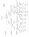
- the method may be illustrated in part, namely for an analog signal A j , as passing through a tree (see Fig. 2) having nodes corresponding to N respective levels corresponding to possible values of the control signal and corresponding comparisons in N respective cycles , Branching into branches below the nodes is done according to the comparison results, so that there are 2 n-1 nodes in the n level corresponding to cycle n.
- the tree shown there on the one hand shows all possible process profiles for an analog signal A j .
- concrete courses are shown for exemplarily given levels of the analog signals or channels.
- the reference level to be set is indicated by specifying the values of the corresponding control signal S ' jn to be set.
- the number in the nodes indicates in each case the control signal value to be set corresponding to the reference level to be set, which is in each case specified again as a formula on the right of the node.
- the channels or the corresponding analog signals are designated by the reference symbols K 1 ,... K 4 .
- the arrows correspond respectively to the movement in the tree according to the comparison results, wherein dashed arrows in the example in Fig. 2 designate theoretically possible paths, which, however, are not traversed in the specific example at the analog signal levels used. Solid arrows correspond to paths for the assumed in the example in Fig. 2 level of the analog signals of the channels K 1 , ... K 4 .
- the only possible reference level namely the level corresponding to the most significant bit, is determined and set for all channels or analog signals. Index 1 therefore assumes the value 1 as the only value.
- the second level two nodes on According to the two possible comparison results, the second level two nodes on.
- all the analog signal levels are compared in parallel with the reference level of the reference signal R 12 , which corresponds to the control signal value S 12 to be set equally for the analog signals.
- the comparison signal for the analog signal A 4 and the channel K 4 is no longer used because the reference level used was not determined for this.
- the method can therefore also be understood as meaning for everyone Appropriate to the weighing procedure, however, the same reference levels occurring at one level for different ones Channels set only once and corresponding comparisons in parallel for all channels.
- the selection of the analog-to-digital conversion for a particular channel to be used for comparison results or signals then takes place through the evaluation device.
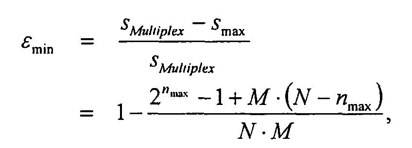
- the largest number of settlements of the reference level results when the levels of the analog signals are such that all possible reference levels have to be set up to a last such cycle n max , ie all nodes are traversed in all levels up to level n max .
- the reduction of the time effort will be between ⁇ min and ⁇ max .
- an analog-to-digital converter 10 ' according to a second preferred Embodiment of the invention in Fig. 3 is compared to the analog-to-digital converter 10 of the first embodiment, only the evaluation 20 replaced by an evaluation device 20 '.
- the evaluation 20 replaced by an evaluation device 20 '.
- the evaluation device 20 differs from the evaluation device 20 by the design of the evaluation logic, a detection device 41 and the control device 36'.
- the control device 36 ' has a simple digital counter, which increments its count by 1 in one cycle from a fixed, predetermined initial value in the cycle for a predetermined number of steps and outputs the result as a control signal S z to the reference signal generator 18 where z is an index representing the count.
- the reference level R z of the reference signal is therefore increased by incrementing the counter or the control device 36 'in equal steps up to a maximum value.
- the detection device 41 is designed to change a Comparison signal controlled by the evaluation logic the value of Read meter.
- the evaluation logic is to carry out appropriate steps of a A method for analog-to-digital conversion according to a second preferred Embodiment of the invention formed.
- the reference level R z of the reference signal is increased from the same initial value in each cycle in equal increments up to a maximum value determined in particular by the number of times for the digital representation of the analog signal level used bit can be determined.
- the evaluation device 20 ' when the comparison signal C jz changes for a corresponding analog signal A j, the counter 36' or the control device is read out and the read value is used as a digital value for the corresponding level of the analog signal A j , for which then a corresponding digital signal D j is formed.
- an analog-to-digital converter 10 shown schematically in FIG. according to a third preferred embodiment of the invention to the analog-to-digital converter 10 of the first embodiment the evaluation device 20 by an evaluation device 20 " and the reference signal generator 18 by a reference signal generator 18 "For all other parts of the embodiment, the same reference numerals as used in the first embodiment and the same explanations apply accordingly.
- the reference signal generator 18 has a sawtooth generator which generates a reference signal with a predetermined time reference level profile which is output via the reference signal output 28 to the reference signal inputs 24 of the comparators 14 1 , ... 14 M.
- the reference signal output 28 is furthermore connected to a reference signal input 42 the evaluation device 20 "connected.
- the evaluation device 20 "has no control device a detection device 44 for time detection provided with the Reference signal input 42 is connected.
- the detection device is in particular designed so that they are at a return of the sawtooth Reference signal in a predetermined start state or is set to a starting value and that from her in the following a time interval from the return reproducing value or a corresponding signal can be read out.
- the evaluation logic of the evaluation device 20 is to carry out corresponding steps of a method for analog-to-digital conversion formed according to a third preferred embodiment of the invention.
- the reference level Rt of the reference signal becomes Dependence on the time t cyclic linear up to a maximum value elevated.
- the detection device 44 is set to the starting value and a time recording is restarted.
- a value for the time elapsed since the return of the sawtooth-shaped reference signal or setting of the starting state is read out of the detection device 44. Based on the predetermined, known rate of change of the reference level and the detected time value, a digital value is then determined which approximately represents the analog signal level. A corresponding digital signal D j is formed and output via a corresponding output.
- fourth to sixth preferred embodiments of the invention are the analog signal inputs of the comparators respectively Er handledsund Holding circuits upstream, connected to the evaluation are connected.
- a signal of the evaluation which in the Determining a digital signal for all channels with or immediately after the formation of the last digital signal, is the level of the respective analog signal of the corresponding Analog signal source newly detected and until the reception of the next signal from the evaluation an analog signal with the detected Level output to the analog signal input of the corresponding comparator.
Landscapes
- Engineering & Computer Science (AREA)
- Theoretical Computer Science (AREA)
- Analogue/Digital Conversion (AREA)
Abstract
Description
- Fig. 1
- ein schematisches Blockschaltbild eines erfindungsgemäßen Analog-Digital-Wandlers nach einer ersten bevorzugten Ausführungsform der Erfindung mit mehreren damit verbundenen Analogsignalquellen,
- Fig. 2
- ein schematisches Diagramm zur Erläuterung des von dem Analog-Digital-Wandler in Fig. 1 verwendeten Verfahrens für den Fall von vier Kanälen und einer Darstellung der Pegel von Analogsignalen der Kanäle durch drei Bits,
- Fig. 3
- ein schematisches Blockschaltbild eines Analog-Digital-Wandlers nach einer zweiten bevorzugten Ausführungsform der Erfindung, und
- Fig. 4
- ein schematisches Blockschaltbild eines Analog-Digital-Wandlers nach einer dritten bevorzugten Ausführungsform der Erfindung.
| S'jn = 2N/2 | f. n = 1,j = 1 bis M |
| S'jn = S'jn-1 + 2N/2n | f. n = 2,3...N,falls Cj,n - 1 = 1b, |
| S'jn = S'jn-1 - 2N/2n | f. n = 2, 3...N, falls Cj,n-1 = 0b. |
| Dj = S'jN | falls CjL(j)N = 1b |
| Dj = S'jN -1 | falls CjL(j)N = 0b. |



- 10, 10', 10"
- Analog-Digital-Wandler
- 121, 122, 12M
- Analogsignalquellen
- 141, 142, 14M
- Kanäle
- 161, 162, 16M
- Komparatoren
- 18, 18"
- Referenzsignalgeneratoren
- 20, 20', 20"
- Auswerteeinrichtung
- 22
- Analogsignaleingänge
- 24
- Referenzsignaleingänge
- 26
- Vergleichssignalausgänge
- 28
- Referenzsignalausgang
- 301, ..., 30M
- Vergleichssignaleingänge
- 32
- Steuersignaleingang
- 34
- Digital-Analog-Wandler
- 36, 36'
- Steuereinrichtungen
- 38
- Steuersignalausgang
- 401, ..., 40M
- Digitalsignalausgänge
- 41
- Erfassungseinrichtung
- 42
- Referenzsignaleingang
- 44
- Erfassungseinrichtung
- Aj
- Analogsignale bzw. -pegel
- Cjln, Cjz, Cjt
- Vergleichssignale bzw. -pegel
- Dj
- Digitalsignale bzw. -werte
- Rln, Rz, Rt
- Referenzsignale bzw. -pegel
- Sln, Sz
- Steuersignale bzw. -pegel
Claims (17)
- Verfahren zur Wandlung von Analogsignalen wenigstens zweier Kanäle (141, ... 14M) in entsprechende, jeweils deren Pegel darstellende Digitalsignale,
bei dem ein Referenzsignal mit einem sich zeitlich ändernden Referenzpegel gebildet wird,
die Pegel der Analogsignale wenigstens zu verschiedenen Zeitpunkten im Wesentlichen parallel mit dem jeweiligen Referenzpegel des Referenzsignals verglichen und für die Analogsignale jeweils entsprechende, das Ergebnis des jeweiligen Vergleichs wiedergebende Vergleichssignale gebildet werden, und
für jedes Analogsignal auf der Basis wenigstens eines der Vergleichssignale für das jeweilige Analogsignal ein dessen Pegel wiedergebendes Digitalsignal gebildet wird. - Verfahren nach Anspruch 1,
dadurch gekennzeichnet, dass in einem ersten Zyklus der Referenzpegel auf einen ersten vorbestimmten Wert gesetzt wird, die Pegel der Analogsignale mit dem Referenzpegel verglichen und für die Analogsignale entsprechende Vergleichssignale gebildet werden,
in aufeinander folgenden Zyklen für jedes Analogsignal ein in dem Zyklus zu setzender Wert für den Referenzpegel ermittelt wird, der jeweils in Abhängigkeit von der Anzahl der seit dem ersten Zyklus abgearbeiteten Zyklen und von Vergleichsergebnissen für das jeweilige Analogsignal in den vorhergehenden Zyklen oder dem für das jeweilige Analogsignal ermittelten Wert des Referenzpegels im vorhergehenden Zyklus in Verbindung mit dem entsprechenden Vergleichsergebnis für das jeweilige Analogsignal des vorhergehenden Zyklus bestimmt ist, der Referenzpegel in dem Zyklus auf alle voneinander verschiedenen ermittelten, zu setzenden Werte gesetzt wird, und die Pegel der Analogsignale parallel mit dem jeweiligen Referenzpegel verglichen und das Ergebnis des jeweiligen Vergleichs wiedergebende Vergleichssignale gebildet werden,
und dass für jedes Analogsignal in Abhängigkeit von Vergleichsergebnissen für das jeweilige Analogsignal, die jeweils bei einem für das Analogsignal ermittelten Wert des Referenzpegel bestimmt wurden, oder wenigstens einem der Vergleichsergebnisse für das Analogsignal, die jeweils bei einem für das Analogsignal ermittelten Referenzpegel bestimmt wurden, und wenigstens einem für das Analogsignal ermittelten Wert des Referenzpegels ein den Pegel des Analogsignals wiedergebendes Digitalsignal gebildet wird. - Verfahren nach Anspruch 2,
dadurch gekennzeichnet, dass die Pegel der Analogsignale durch eine vorgegebene Anzahl von Bits dargestellt werden, und
dass der erste Wert des Referenzpegels einem durch das höchstwertigen Bit dargestellten Pegel entspricht. - Verfahren nach Anspruch 3,
dadurch gekennzeichnet, dass der zu setzende Wert des Referenzpegels für ein Analogsignal in einem Zyklus n gegenüber dem entsprechenden, in dem vorhergehenden Zyklus ermittelten, zu setzenden Wert des Referenzpegels für das Analogsignal um den Wert des Referenzpegels im ersten Zyklus dividiert durch 2n-1 reduziert ist, wenn im vorhergehenden Zyklus der Pegel des Analogsignals kleiner als der Referenzpegel war, während dieser auf den für das Analogsignal als zu setzend ermittelten Wert gesetzt war, und um den Wert des Referenzpegels im ersten Zyklus dividiert durch 2n-1 erhöht ist, wenn im vorhergehenden Zyklus der Pegel des Analogsignals größer als der Referenzpegel war, während dieser auf den für das Analogsignal als zu setzend ermittelten Wert gesetzt war,
wobei n die Ordinalzahl des Zyklus bezeichnet. - Verfahren nach Anspruch 1,
dadurch gekennzeichnet, dass der Referenzpegel als vorgegebene Funktion der Zeit zyklisch verändert wird, und
dass bei einer Änderung des Vergleichsergebnisses für ein Analogsignal während eines Zyklus der Zeitpunkt der Änderung erfasst und in Abhängigkeit von der Lage des Zeitpunkts in dem Zyklus das Digitalsignal gebildet wird. - Verfahren nach Anspruch 1 oder 5,
dadurch gekennzeichnet, dass in aufeinander folgenden Zyklen der Referenzpegel jeweils als vorgegebene Funktion der Zeit schrittweise verändert wird, und dass bei einer Änderung des Vergleichsergebnisses für ein Analogsignal auf der Basis der Anzahl der Änderungsschritte in einem aktuellen Zyklus das entsprechende Digitalsignal gebildet wird. - Verfahren nach einem der vorhergehenden Ansprüche,
dadurch gekennzeichnet, dass die Referenzsignale durch eine Digital-Analog-Wandlung gebildet werden. - Verfahren nach einem der vorhergehenden Ansprüche,
dadurch gekennzeichnet, dass der Pegel wenigstens eines der Analogsignale während der Dauer der Bildung jeweils eines Digitalwerts für alle Kanäle (141, ... 14M) im Wesentlichen konstant gehalten wird. - Analog-Digital-Wandler zur Wandlung von Analogsignalen wenigstens zweier Kanäle (141, ... 14M) in entsprechende, jeweils deren Pegel darstellende Digitalsignale, mit
einem Referenzsignalgenerator (18; 18") zur Bildung eines zeitlich veränderlichen Referenzsignals und zur Abgabe des Referenzsignals über einen Referenzsignalausgang (28),
jeweils einem Komparator (161, ... 16M) für jeden der Kanäle (141, ... 14M), der einen Analogsignaleingang (22) zur Zuführung des Analogsignals des entsprechenden Kanals (141, ..., 14M) und einen mit dem Referenzsignalausgang (28) verbundenen Referenzsignaleingang (24) aufweist und mittels dessen der Pegel des jeweiligen Analogsignals mit einem Referenzpegel des Referenzsignals vergleichbar und ein entsprechendes, ein Ergebnis des Vergleichs wiedergebendes Vergleichssignal über einen Vergleichssignalausgang (26) des Komparators (161, ... 16M) ausgebbar ist, und
einer Auswerteeinrichtung (20; 20'; 20"), die mit den Vergleichssignalausgängen der Komparatoren (161, ... 16M) und mit dem Referenzsignalgenerator (18; 18") verbunden ist und mittels derer in Abhängigkeit von den empfangenen Vergleichssignalen für die Analogsignale entsprechende, die Pegel der Analogsignale wiedergebende Digitalsignale bildbar und abgebbar sind. - Analog-Digital-Wandler nach Anspruch 9,
dadurch gekennzeichnet, dass der Referenzsignalgenerator (18) durch Steuersignale an einem Steuersignaleingang (32) des Referenzsignalgenerators (18) steuerbar ist, und
dass die Auswerteeinrichtung (20) eine Steuereinrichtung (36) aufweist, die mit dem Steuersignaleingang (32) verbunden ist und mittels derer der Referenzsignalgenerator (18) so steuerbar ist, dass
in einem ersten Zyklus der Referenzpegel auf einen ersten vorbestimmten Wert gesetzt wird, und
in aufeinander folgenden Zyklen für jedes Analogsignal ein in dem Zyklus zu setzender Wert für den Referenzpegel ermittelt wird, der jeweils in Abhängigkeit von der Anzahl der seit dem ersten Zyklus abgearbeiteten Zyklen und von Vergleichsergebnissen für das jeweilige Analogsignal in den vorhergehenden Zyklen oder dem für das jeweilige Analogsignal ermittelten Wert des Referenzpegels im vorhergehenden Zyklus in Verbindung mit dem entsprechenden Vergleichsergebnis für das jeweilige Analogsignal des vorhergehenden Zyklus bestimmt ist, und der Referenzpegel in dem Zyklus auf alle voneinander verschiedenen ermittelten, zu setzenden Werte gesetzt wird,
und dass die Auswerteeinrichtung (20) weiter so ausgebildet ist, dass für jedes Analogsignal in Abhängigkeit von Vergleichsergebnissen für das jeweilige Analogsignal, die jeweils bei einem für das Analogsignal ermittelten des Referenzpegel bestimmt wurden, oder wenigstens einem der Vergleichsergebnisse für das Analogsignal, die jeweils bei einem für das Analogsignal ermittelten Referenzpegel bestimmt wurden, und wenigstens einem für das Analogsignal ermittelten Wert des Referenzpegels Daten ermittelbar sind, die den Pegel des Analogsignals wiedergeben. - Analog-Digital-Wandler nach Anspruch 9 oder 10,
dadurch gekennzeichnet, dass die Auswerteeinrichtung (20) so ausgebildet ist, dass die Pegel der Analogsignale durch eine vorgegebene Anzahl von Bits dargestellt werden, und
dass die Steuereinrichtung (36) so ausgebildet ist, dass der erste Wert des Referenzpegels einem durch das höchstwertige Bit dargestellten Pegel entspricht. - Analog-Digital-Wandler nach Anspruch 11,
dadurch gekennzeichnet, dass die Steuereinrichtung (36) so ausgebildet ist, dass der zu setzende Wert des Referenzpegels für ein Analogsignal in einem Zyklus n gegenüber dem entsprechenden, in dem vorhergehenden Zyklus ermittelten, zu setzenden Wert des Referenzpegels für das Analogsignal um den Wert des Referenzpegels im ersten Zyklus dividiert durch 2n-1 reduziert ist, wenn im vorhergehenden Zyklus der Pegel des Analogsignals kleiner als der Referenzpegel war, während dieser auf den für das Analogsignal als zu setzend ermittelten Wert gesetzt war, und um den Wert des Referenzpegels im ersten Zyklus dividiert durch 2n-1 erhöht ist, wenn im vorhergehenden Zyklus der Pegel des Analogsignals größer als der Referenzpegel war, während dieser auf den für das Analogsignal als zu setzend ermittelten Wert gesetzt war,
wobei n die Ordinalzahl des Zyklus bezeichnet. - Analog-Digital-Wandler nach Anspruch 9,
dadurch gekennzeichnet, dass der Referenzsignalgenerator (18") zur Bildung eines Referenzsignals mit einem Referenzpegel ausgebildet ist, der sich als vorgegebene Funktion der Zeit zyklisch ändert,
dass der Referenzsignalausgang (28) mit einem Referenzsignaleingang (24) der Auswerteeinrichtung (20") verbunden ist, und
dass die Auswerteeinrichtung (20") eine Einrichtung zur Ermittlung des Referenzpegels in Abhängigkeit von empfangenen Vergleichssignalen aufweist. - Analog-Digital-Wandler nach Anspruche 9 oder 13,
dadurch gekennzeichnet,
die Auswerteeinrichtung (20') eine Steuereinrichtung (36') aufweist, mittels derer Steuersignale an den Referenzsignalgenerator (18) ausgebbar sind, so dass der Referenzpegel des Referenzsignals in aufeinander folgenden Zyklen jeweils als vorgegebene Funktion der Zeit schrittweise verändert wird, und
dass die Auswerteeinrichtung (20') so ausgebildet ist, dass bei einer Änderung des Vergleichsergebnisses für ein Analogsignal auf der
Basis der Anzahl der Änderungsschritte in einem aktuellen Zyklus das entsprechende Digitalsignal gebildet wird. - Analog-Digital-Wandler nach einem der Ansprüche 9 bis 14,
dadurch gekennzeichnet, dass der Referenzsignalgenerator (18) einen Digital-Analog-Wandler (34) umfasst, dessen Ausgang mit dem Referenzsignalausgang (28) verbunden ist. - Analog-Digital-Wandler nach Anspruch 14 und Anspruch 15,
dadurch gekennzeichnet, dass die Steuereinrichtung (36') einen Zähler aufweist, mittels dessen der Digital-Analog-Wandler (34) ansteuerbar ist, und
dass die Auswerteeinrichtung (20') eine Erfassungseinrichtung (41) aufweist, mittels derer bei Änderung eines Vergleichssignals der Wert des Zählers erfassbar ist. - Analog-Digital-Wandler nach einem der Ansprüche 9 bis 16,
gekennzeichnet durch
wenigstens eine vor den Analogsignaleingang wenigstens eines der Komparatoren geschaltete Erfassungs- und Halteschaltung.
Priority Applications (3)
| Application Number | Priority Date | Filing Date | Title |
|---|---|---|---|
| EP03025666A EP1530295B1 (de) | 2003-11-07 | 2003-11-07 | Verfahren zur Analog-Digital-Wandlung und Analog-Digital-Wandler |
| AT03025666T ATE343251T1 (de) | 2003-11-07 | 2003-11-07 | Verfahren zur analog-digital-wandlung und analog- digital-wandler |
| DE50305435T DE50305435D1 (de) | 2003-11-07 | 2003-11-07 | Verfahren zur Analog-Digital-Wandlung und Analog-Digital-Wandler |
Applications Claiming Priority (1)
| Application Number | Priority Date | Filing Date | Title |
|---|---|---|---|
| EP03025666A EP1530295B1 (de) | 2003-11-07 | 2003-11-07 | Verfahren zur Analog-Digital-Wandlung und Analog-Digital-Wandler |
Publications (2)
| Publication Number | Publication Date |
|---|---|
| EP1530295A1 true EP1530295A1 (de) | 2005-05-11 |
| EP1530295B1 EP1530295B1 (de) | 2006-10-18 |
Family
ID=34429306
Family Applications (1)
| Application Number | Title | Priority Date | Filing Date |
|---|---|---|---|
| EP03025666A Expired - Lifetime EP1530295B1 (de) | 2003-11-07 | 2003-11-07 | Verfahren zur Analog-Digital-Wandlung und Analog-Digital-Wandler |
Country Status (3)
| Country | Link |
|---|---|
| EP (1) | EP1530295B1 (de) |
| AT (1) | ATE343251T1 (de) |
| DE (1) | DE50305435D1 (de) |
Citations (2)
| Publication number | Priority date | Publication date | Assignee | Title |
|---|---|---|---|---|
| WO1990011613A1 (en) * | 1989-03-27 | 1990-10-04 | Irvine Sensors Corporation | Analog to digital conversion incorporated in z-technology module |
| US5801657A (en) * | 1997-02-05 | 1998-09-01 | Stanford University | Serial analog-to-digital converter using successive comparisons |
-
2003
- 2003-11-07 DE DE50305435T patent/DE50305435D1/de not_active Expired - Lifetime
- 2003-11-07 EP EP03025666A patent/EP1530295B1/de not_active Expired - Lifetime
- 2003-11-07 AT AT03025666T patent/ATE343251T1/de not_active IP Right Cessation
Patent Citations (2)
| Publication number | Priority date | Publication date | Assignee | Title |
|---|---|---|---|---|
| WO1990011613A1 (en) * | 1989-03-27 | 1990-10-04 | Irvine Sensors Corporation | Analog to digital conversion incorporated in z-technology module |
| US5801657A (en) * | 1997-02-05 | 1998-09-01 | Stanford University | Serial analog-to-digital converter using successive comparisons |
Non-Patent Citations (1)
| Title |
|---|
| CLIFF R A: "DIGITAL MULTIPLEXING OF ANALOG DATA IN A MICROPROCESSOR CONTROLLED DATA ACQUISITION SYSTEM", IEEE JOURNAL OF SOLID-STATE CIRCUITS, IEEE INC. NEW YORK, US, vol. SC-15, no. 1, February 1980 (1980-02-01), pages 136 - 138, XP000798099, ISSN: 0018-9200 * |
Also Published As
| Publication number | Publication date |
|---|---|
| ATE343251T1 (de) | 2006-11-15 |
| DE50305435D1 (de) | 2006-11-30 |
| EP1530295B1 (de) | 2006-10-18 |
Similar Documents
| Publication | Publication Date | Title |
|---|---|---|
| DE2820425C2 (de) | Binärer Zufallsrauschgenerator zur stochastischen Kodierung | |
| DE2536585C3 (de) | Anordnung zur statistischen Signalanalyse | |
| DE3622584C2 (de) | Verfahren und Vorrichtung zur Regulierung des Verzugs eines Faserbands bei einer Textilmaschine | |
| DE3818546C2 (de) | ||
| DE2838849A1 (de) | Analog-digital-umsetzer | |
| EP4242595A1 (de) | Vorrichtung und verfahren zur positions-, längen- oder winkelbestimmung | |
| DE2946502A1 (de) | Verfahren und schaltungsanordnung zur digitalen auswertung von analogsignalen grosser amplitudendynamik | |
| EP0141906B1 (de) | Antiblockierregelsystem | |
| DE3751355T2 (de) | Hochauflösender schneller Analog/Digitalwandler. | |
| DE4005037C2 (de) | ||
| EP1530295B1 (de) | Verfahren zur Analog-Digital-Wandlung und Analog-Digital-Wandler | |
| DE2230540C2 (de) | Vorricntung zur Feststellung einer kritischen Radverzögerung für Antiblockiergeräte | |
| DE2430018B2 (de) | Anordnung zur stufenlosen Kompression digital gespeicherter Datenfolgen zwecks analoger Wiedergabe | |
| DE2743410C3 (de) | Verfahren zur zeitlichen Stabilisierung periodischer Abtastimpulse und Anordnungen zur Durchführung des Verfahrens | |
| DE19631972C2 (de) | Verfahren zum Überwachen der Funktionsfähigkeit eines zur Digitalisierung von Analogsignalen ausgelegten Analog/-Digital Wandlers | |
| DE102004049459A1 (de) | Lenkwinkelgeschwindigkeits-Detektorvorrichtung | |
| DE2657915B2 (de) | Verfahren und Vorrichtung zur digitalen Messung analoger Größen | |
| DE3151627C2 (de) | ||
| DE2150174A1 (de) | Vorrichtung zur Anzeige des Endes eines chromatographischen Signals | |
| DE19922060C2 (de) | Verfahren zur Umwandlung eines digitalen Signals | |
| DE4413566C2 (de) | Elektrische Schaltungsanordnung | |
| EP1234283B1 (de) | Verfahren und anordnung zum betreiben eines mehrstufigen zählers in einer zählrichtung | |
| DE2538185C3 (de) | Digitaler Impulsratenmesser mit angenähert logarithmischer Kennlinie | |
| DE2830304C2 (de) | Analog-Digitalwandler | |
| DE3436587A1 (de) | Verfahren und vorrichtung zur digitalen entfernungsmessung und mit einer solchen vorrichtung ausgeruestetes radar |
Legal Events
| Date | Code | Title | Description |
|---|---|---|---|
| PUAI | Public reference made under article 153(3) epc to a published international application that has entered the european phase |
Free format text: ORIGINAL CODE: 0009012 |
|
| AK | Designated contracting states |
Kind code of ref document: A1 Designated state(s): AT BE BG CH CY CZ DE DK EE ES FI FR GB GR HU IE IT LI LU MC NL PT RO SE SI SK TR |
|
| AX | Request for extension of the european patent |
Extension state: AL LT LV MK |
|
| 17P | Request for examination filed |
Effective date: 20050630 |
|
| AKX | Designation fees paid |
Designated state(s): AT BE BG CH CY CZ DE DK EE ES FI FR GB GR HU IE IT LI LU MC NL PT RO SE SI SK TR |
|
| GRAP | Despatch of communication of intention to grant a patent |
Free format text: ORIGINAL CODE: EPIDOSNIGR1 |
|
| GRAS | Grant fee paid |
Free format text: ORIGINAL CODE: EPIDOSNIGR3 |
|
| GRAA | (expected) grant |
Free format text: ORIGINAL CODE: 0009210 |
|
| AK | Designated contracting states |
Kind code of ref document: B1 Designated state(s): AT BE BG CH CY CZ DE DK EE ES FI FR GB GR HU IE IT LI LU MC NL PT RO SE SI SK TR |
|
| PG25 | Lapsed in a contracting state [announced via postgrant information from national office to epo] |
Ref country code: FI Free format text: LAPSE BECAUSE OF FAILURE TO SUBMIT A TRANSLATION OF THE DESCRIPTION OR TO PAY THE FEE WITHIN THE PRESCRIBED TIME-LIMIT Effective date: 20061018 Ref country code: IT Free format text: LAPSE BECAUSE OF FAILURE TO SUBMIT A TRANSLATION OF THE DESCRIPTION OR TO PAY THE FEE WITHIN THE PRESCRIBED TIME-LIMIT;WARNING: LAPSES OF ITALIAN PATENTS WITH EFFECTIVE DATE BEFORE 2007 MAY HAVE OCCURRED AT ANY TIME BEFORE 2007. THE CORRECT EFFECTIVE DATE MAY BE DIFFERENT FROM THE ONE RECORDED. Effective date: 20061018 Ref country code: RO Free format text: LAPSE BECAUSE OF FAILURE TO SUBMIT A TRANSLATION OF THE DESCRIPTION OR TO PAY THE FEE WITHIN THE PRESCRIBED TIME-LIMIT Effective date: 20061018 Ref country code: NL Free format text: LAPSE BECAUSE OF FAILURE TO SUBMIT A TRANSLATION OF THE DESCRIPTION OR TO PAY THE FEE WITHIN THE PRESCRIBED TIME-LIMIT Effective date: 20061018 Ref country code: IE Free format text: LAPSE BECAUSE OF FAILURE TO SUBMIT A TRANSLATION OF THE DESCRIPTION OR TO PAY THE FEE WITHIN THE PRESCRIBED TIME-LIMIT Effective date: 20061018 Ref country code: SI Free format text: LAPSE BECAUSE OF FAILURE TO SUBMIT A TRANSLATION OF THE DESCRIPTION OR TO PAY THE FEE WITHIN THE PRESCRIBED TIME-LIMIT Effective date: 20061018 Ref country code: SK Free format text: LAPSE BECAUSE OF FAILURE TO SUBMIT A TRANSLATION OF THE DESCRIPTION OR TO PAY THE FEE WITHIN THE PRESCRIBED TIME-LIMIT Effective date: 20061018 Ref country code: CZ Free format text: LAPSE BECAUSE OF FAILURE TO SUBMIT A TRANSLATION OF THE DESCRIPTION OR TO PAY THE FEE WITHIN THE PRESCRIBED TIME-LIMIT Effective date: 20061018 |
|
| REG | Reference to a national code |
Ref country code: GB Ref legal event code: FG4D Free format text: NOT ENGLISH |
|
| REG | Reference to a national code |
Ref country code: IE Ref legal event code: FG4D Free format text: LANGUAGE OF EP DOCUMENT: GERMAN Ref country code: CH Ref legal event code: EP |
|
| PG25 | Lapsed in a contracting state [announced via postgrant information from national office to epo] |
Ref country code: MC Free format text: LAPSE BECAUSE OF NON-PAYMENT OF DUE FEES Effective date: 20061130 Ref country code: BE Free format text: LAPSE BECAUSE OF NON-PAYMENT OF DUE FEES Effective date: 20061130 |
|
| REF | Corresponds to: |
Ref document number: 50305435 Country of ref document: DE Date of ref document: 20061130 Kind code of ref document: P |
|
| PG25 | Lapsed in a contracting state [announced via postgrant information from national office to epo] |
Ref country code: SE Free format text: LAPSE BECAUSE OF FAILURE TO SUBMIT A TRANSLATION OF THE DESCRIPTION OR TO PAY THE FEE WITHIN THE PRESCRIBED TIME-LIMIT Effective date: 20070118 Ref country code: BG Free format text: LAPSE BECAUSE OF FAILURE TO SUBMIT A TRANSLATION OF THE DESCRIPTION OR TO PAY THE FEE WITHIN THE PRESCRIBED TIME-LIMIT Effective date: 20070118 Ref country code: DK Free format text: LAPSE BECAUSE OF FAILURE TO SUBMIT A TRANSLATION OF THE DESCRIPTION OR TO PAY THE FEE WITHIN THE PRESCRIBED TIME-LIMIT Effective date: 20070118 |
|
| PG25 | Lapsed in a contracting state [announced via postgrant information from national office to epo] |
Ref country code: ES Free format text: LAPSE BECAUSE OF FAILURE TO SUBMIT A TRANSLATION OF THE DESCRIPTION OR TO PAY THE FEE WITHIN THE PRESCRIBED TIME-LIMIT Effective date: 20070129 |
|
| PG25 | Lapsed in a contracting state [announced via postgrant information from national office to epo] |
Ref country code: PT Free format text: LAPSE BECAUSE OF FAILURE TO SUBMIT A TRANSLATION OF THE DESCRIPTION OR TO PAY THE FEE WITHIN THE PRESCRIBED TIME-LIMIT Effective date: 20070319 |
|
| NLV1 | Nl: lapsed or annulled due to failure to fulfill the requirements of art. 29p and 29m of the patents act | ||
| ET | Fr: translation filed | ||
| GBV | Gb: ep patent (uk) treated as always having been void in accordance with gb section 77(7)/1977 [no translation filed] |
Effective date: 20061018 |
|
| REG | Reference to a national code |
Ref country code: IE Ref legal event code: FD4D |
|
| PLBE | No opposition filed within time limit |
Free format text: ORIGINAL CODE: 0009261 |
|
| STAA | Information on the status of an ep patent application or granted ep patent |
Free format text: STATUS: NO OPPOSITION FILED WITHIN TIME LIMIT |
|
| 26N | No opposition filed |
Effective date: 20070719 |
|
| PG25 | Lapsed in a contracting state [announced via postgrant information from national office to epo] |
Ref country code: GB Free format text: LAPSE BECAUSE OF FAILURE TO SUBMIT A TRANSLATION OF THE DESCRIPTION OR TO PAY THE FEE WITHIN THE PRESCRIBED TIME-LIMIT Effective date: 20061018 |
|
| BERE | Be: lapsed |
Owner name: DELPHI TECHNOLOGIES, INC. Effective date: 20061130 |
|
| PG25 | Lapsed in a contracting state [announced via postgrant information from national office to epo] |
Ref country code: AT Free format text: LAPSE BECAUSE OF NON-PAYMENT OF DUE FEES Effective date: 20061107 |
|
| PG25 | Lapsed in a contracting state [announced via postgrant information from national office to epo] |
Ref country code: GR Free format text: LAPSE BECAUSE OF FAILURE TO SUBMIT A TRANSLATION OF THE DESCRIPTION OR TO PAY THE FEE WITHIN THE PRESCRIBED TIME-LIMIT Effective date: 20070119 |
|
| PG25 | Lapsed in a contracting state [announced via postgrant information from national office to epo] |
Ref country code: EE Free format text: LAPSE BECAUSE OF FAILURE TO SUBMIT A TRANSLATION OF THE DESCRIPTION OR TO PAY THE FEE WITHIN THE PRESCRIBED TIME-LIMIT Effective date: 20061018 |
|
| PG25 | Lapsed in a contracting state [announced via postgrant information from national office to epo] |
Ref country code: LU Free format text: LAPSE BECAUSE OF NON-PAYMENT OF DUE FEES Effective date: 20061107 Ref country code: LI Free format text: LAPSE BECAUSE OF NON-PAYMENT OF DUE FEES Effective date: 20071130 Ref country code: HU Free format text: LAPSE BECAUSE OF FAILURE TO SUBMIT A TRANSLATION OF THE DESCRIPTION OR TO PAY THE FEE WITHIN THE PRESCRIBED TIME-LIMIT Effective date: 20070419 Ref country code: TR Free format text: LAPSE BECAUSE OF FAILURE TO SUBMIT A TRANSLATION OF THE DESCRIPTION OR TO PAY THE FEE WITHIN THE PRESCRIBED TIME-LIMIT Effective date: 20061018 Ref country code: CH Free format text: LAPSE BECAUSE OF NON-PAYMENT OF DUE FEES Effective date: 20071130 |
|
| REG | Reference to a national code |
Ref country code: CH Ref legal event code: PL |
|
| PG25 | Lapsed in a contracting state [announced via postgrant information from national office to epo] |
Ref country code: CY Free format text: LAPSE BECAUSE OF FAILURE TO SUBMIT A TRANSLATION OF THE DESCRIPTION OR TO PAY THE FEE WITHIN THE PRESCRIBED TIME-LIMIT Effective date: 20061018 |
|
| REG | Reference to a national code |
Ref country code: FR Ref legal event code: TP Owner name: DELPHI INTERNATIONAL OPERATIONS LUXEMBOURG S.A, LU Effective date: 20131218 |
|
| REG | Reference to a national code |
Ref country code: DE Ref legal event code: R082 Ref document number: 50305435 Country of ref document: DE Representative=s name: MANITZ, FINSTERWALD & PARTNER GBR, DE |
|
| REG | Reference to a national code |
Ref country code: DE Ref legal event code: R082 Ref document number: 50305435 Country of ref document: DE Representative=s name: MANITZ, FINSTERWALD & PARTNER GBR, DE Effective date: 20140409 Ref country code: DE Ref legal event code: R081 Ref document number: 50305435 Country of ref document: DE Owner name: DELPHI INTERNATIONAL OPERATIONS LUXEMBOURG S.A, LU Free format text: FORMER OWNER: DELPHI TECHNOLOGIES, INC., TROY, US Effective date: 20140409 Ref country code: DE Ref legal event code: R081 Ref document number: 50305435 Country of ref document: DE Owner name: DELPHI INTERNATIONAL OPERATIONS LUXEMBOURG S.A, LU Free format text: FORMER OWNER: DELPHI TECHNOLOGIES, INC., TROY, MICH., US Effective date: 20140409 Ref country code: DE Ref legal event code: R082 Ref document number: 50305435 Country of ref document: DE Representative=s name: MANITZ FINSTERWALD PATENTANWAELTE PARTMBB, DE Effective date: 20140409 |
|
| REG | Reference to a national code |
Ref country code: FR Ref legal event code: PLFP Year of fee payment: 13 |
|
| REG | Reference to a national code |
Ref country code: FR Ref legal event code: PLFP Year of fee payment: 14 |
|
| REG | Reference to a national code |
Ref country code: FR Ref legal event code: PLFP Year of fee payment: 15 |
|
| REG | Reference to a national code |
Ref country code: DE Ref legal event code: R081 Ref document number: 50305435 Country of ref document: DE Owner name: APTIV TECHNOLOGIES LIMITED, BB Free format text: FORMER OWNER: DELPHI INTERNATIONAL OPERATIONS LUXEMBOURG S.A R.L., 4940 HAUTCHARAGE, LU Ref country code: DE Ref legal event code: R082 Ref document number: 50305435 Country of ref document: DE Representative=s name: MANITZ FINSTERWALD PATENT- UND RECHTSANWALTSPA, DE Ref country code: DE Ref legal event code: R082 Ref document number: 50305435 Country of ref document: DE Representative=s name: MANITZ FINSTERWALD PATENTANWAELTE PARTMBB, DE Ref country code: DE Ref legal event code: R081 Ref document number: 50305435 Country of ref document: DE Owner name: APTIV TECHNOLOGIES LIMITED, BB Free format text: FORMER OWNER: DELPHI INTERNATIONAL OPERATIONS LUXEMBOURG S.A R.L., 4940 BASCHARAGE, LU |
|
| PGFP | Annual fee paid to national office [announced via postgrant information from national office to epo] |
Ref country code: IT Payment date: 20221122 Year of fee payment: 20 Ref country code: FR Payment date: 20221128 Year of fee payment: 20 Ref country code: DE Payment date: 20221116 Year of fee payment: 20 |
|
| P01 | Opt-out of the competence of the unified patent court (upc) registered |
Effective date: 20230425 |
|
| REG | Reference to a national code |
Ref country code: DE Ref legal event code: R071 Ref document number: 50305435 Country of ref document: DE |