EP1530109A2 - Ventilator-Anlage und Verfahren zur Regelung des Luftstroms einer Ventilator-Anlage - Google Patents
Ventilator-Anlage und Verfahren zur Regelung des Luftstroms einer Ventilator-Anlage Download PDFInfo
- Publication number
- EP1530109A2 EP1530109A2 EP04017423A EP04017423A EP1530109A2 EP 1530109 A2 EP1530109 A2 EP 1530109A2 EP 04017423 A EP04017423 A EP 04017423A EP 04017423 A EP04017423 A EP 04017423A EP 1530109 A2 EP1530109 A2 EP 1530109A2
- Authority
- EP
- European Patent Office
- Prior art keywords
- fan system
- fan
- plates
- outlet opening
- pair
- Prior art date
- Legal status (The legal status is an assumption and is not a legal conclusion. Google has not performed a legal analysis and makes no representation as to the accuracy of the status listed.)
- Granted
Links
Images


Classifications
-
- F—MECHANICAL ENGINEERING; LIGHTING; HEATING; WEAPONS; BLASTING
- F04—POSITIVE - DISPLACEMENT MACHINES FOR LIQUIDS; PUMPS FOR LIQUIDS OR ELASTIC FLUIDS
- F04D—NON-POSITIVE-DISPLACEMENT PUMPS
- F04D29/00—Details, component parts, or accessories
- F04D29/40—Casings; Connections of working fluid
- F04D29/42—Casings; Connections of working fluid for radial or helico-centrifugal pumps
- F04D29/4206—Casings; Connections of working fluid for radial or helico-centrifugal pumps especially adapted for elastic fluid pumps
- F04D29/4226—Fan casings
- F04D29/4253—Fan casings with axial entry and discharge
-
- F—MECHANICAL ENGINEERING; LIGHTING; HEATING; WEAPONS; BLASTING
- F04—POSITIVE - DISPLACEMENT MACHINES FOR LIQUIDS; PUMPS FOR LIQUIDS OR ELASTIC FLUIDS
- F04D—NON-POSITIVE-DISPLACEMENT PUMPS
- F04D17/00—Radial-flow pumps, e.g. centrifugal pumps; Helico-centrifugal pumps
- F04D17/08—Centrifugal pumps
- F04D17/16—Centrifugal pumps for displacing without appreciable compression
- F04D17/165—Axial entry and discharge
-
- F—MECHANICAL ENGINEERING; LIGHTING; HEATING; WEAPONS; BLASTING
- F04—POSITIVE - DISPLACEMENT MACHINES FOR LIQUIDS; PUMPS FOR LIQUIDS OR ELASTIC FLUIDS
- F04D—NON-POSITIVE-DISPLACEMENT PUMPS
- F04D29/00—Details, component parts, or accessories
- F04D29/66—Combating cavitation, whirls, noise, vibration or the like; Balancing
- F04D29/661—Combating cavitation, whirls, noise, vibration or the like; Balancing especially adapted for elastic fluid pumps
- F04D29/663—Sound attenuation
- F04D29/664—Sound attenuation by means of sound absorbing material
Definitions
- the invention relates to a fan system and a method for control the air flow of a fan system.
- the present invention relates in particular, but not exclusively, to on a fan air flow control to mitigate the noise at a fan in a clean room facility.
- baffles There may be two pairs of baffles arranged in the fan unit be, with the baffles are each vertical.
- the guide baffles can set the outlet opening.
- the guide baffles can at an angle of 90 ° and 60 °, preferably 90 ° to at least one Be arranged side.
- the baffle plates can be perforated. The perforation can spread over the entire baffle plates or just over one Part of it extend, and the baffle plates can be covered by a cloth be.
- the baffles can be bent or flat.
- the outlet opening may take the form of: circular, triangular, square, rectangular, pentagonal or octagonal.
- At least one pair of plates in the fan unit are arranged and located between the upper end and at least extend one side and are each connected thereto, wherein at least a pair of plates defines an enclosed space behind it. It can two pairs of plates may be present, with the plates each perpendicular stand. At least one of the plates can be perforated. The perforations can spread over the entire area or over part of at least one the plates extend.
- the plates can be curved or flat, and the Plates can be covered by a cloth.
- the enclosed space can with be filled with a noise insulating material.
- a noise insulating material may be used to form an inner surface of one or more of the following parts: at least one side, the Headboard, the guide baffles and the plates.
- a noise insulating material can be attached on the surface of the fan frame.
- the surface can be a bottom.
- the Blower rack can be in the form of a reverse floor with related Side walls are present, the noise insulating material is in the ground.
- the headboard may have a central opening.
- the central opening can be a Inlet cover, wherein the inlet opening in the inlet cover is arranged.
- a filter may be located below the outlet opening.
- At least one side may consist of four vertical sides, wherein the Pages also each perpendicular to the headboard.
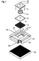
- FIG. 1 shows a perspective exploded view of individual parts a preferred embodiment of the present invention as part of a Fan unit.
- the fan system includes four vertical side walls 22 and an annular head portion 17 having a central opening 10.
- the fan unit is shown in a square shape, it can be one have any shape, such as cylindrical, triangular, rectangular, pentagonal, octagonal, etc.
- the central opening 10 is shown in square. She can also do another take appropriate form, e.g. round, triangular, rectangular, five-cornered, octagonal, etc. Preferably, the shape of the central opening 10 is similar to that of FIG Shape of the fan system.
- the air inlet cover 11 lies above the central opening 10 and closes it from.
- the cover 11 covers the central opening 10 and is in dimensions larger than opening 10, so that they are the head part 17 along the outer surface the opening 10 touched.
- the cover 11 is safe, removable and largely flush sealed connected to the head part 17.
- the cover 11 is also annular and has a central air inlet opening 18.
- the inlet opening 18 is shown around. It can be any shape ever as required or desired, e.g. triangular, quadrangular, rectangular, five angular, octagonal, etc. There may be more than one inlet port 18 give.
- a wind turbine fan 12 is mounted on a fan blower frame 14, the associated side walls 15 may have.
- the frame 14 may be flat.
- the frame 14 may also be reversible. Attached to the fan frame 14 extend from there four rods 13 upwards, which are also releasably connected to the air inlet cover 11.
- a motor for generating rotational movements for the wind turbine fan 12 is Not shown, but required for normal operation of the fan system.
- the frame 14 may be larger in size than the outlet opening 19 in the horizontal plane, making it over the outer surface of the Outlet opening 19 extends.
- the frame 14 may also be in dimensions smaller than the outlet opening 19 in the horizontal plane.
- the dimensions of the frame 14 may be of the dimensions of the wind turbine 12th be dependent.
- the size of the wind turbine fan 12 may differ from the power requirements dependent on a user.
- the frame 14 does not have to be individual be prepared wind turbine fan rack.
- the wind turbine fan 12 in the fan system located and may be mounted on its frame 14.
- the frame 14 can from the head part 17 via the connection of the rods 13 with the inlet cover 11 hang down, and the inlet cover 11 can from the headboard 17 are supported.
- maintenance or Replacement works the fan 12 easily removed through the central opening 10 become.
- the central opening should be a corresponding size to have.
- the fan unit automatically blows outside air through the air inlet 18, such as represented by the arrows 1 in Figure 2.
- the air is passing through the outlet 19 ejected, as shown by the arrows 2 in Figure 2.
- the Auslrawöffimng 19 is square shown. It can take any suitable or desired form, such as. circular, triangular, rectangular, pentagonal, octagonal, etc. Es may be more than one outlet port 19.
- the filter 32 may be spaced can be arranged in front of the outlet opening 19, or he can directly lie next to the outlet opening 19.
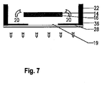
- the baffles 28 are at strategic locations within the Fan system attached to mitigate the noise there and they can are also located along the path of the airflow.
- the baffles 28 extend inwardly from the lower end of side 22.
- At least a pair of the guide baffles 28 are on opposite sides of the outlet opening 19 is mounted and extends inwardly from the side walls 22 to the outlet port 19.
- the baffles 28 of the pair are substantially identical, opposite, parallel and coplanar.
- the Guide baffles 28 form with the side walls at an angle of 90 ° 60 °, preferably 90 °.
- the guide baffles 28 may also define the outlet opening 19.
- the guide baffles 28 can be flat, as shown, or they can be curved be. If they are curved, they can down to the outlet opening 19 to be curved. This is illustrated in FIG.
- FIG. 3 shows a complete cross-section along the straight lines A-A in FIG Figure 2 and highlights the guide baffles 28.
- the guide baffles 28 are arranged so that they the expelled air from the fan blower 12th can record (see dashed circle) and the air flow 3 inside the fan system with a minimum of turbulence to and through the Outlet opening 19 can conduct.
- each plate 26 perpendicular to one another standing.
- the plates 26 extend between the head part 17 and the sides 22 and are preferably at an angle between 30 ° and 60 °, preferably 45 °, to the sides 22, and therefore at an angle between 60 ° and 30 °, preferably 45 °, to the header 17.
- Each panel 26 may be a metal panel and can be a matrix with holes or perforations over have their entire surface or parts thereof.
- noise insulating materials 6 and / or for example in the form of Sponge, fiberglass, rock wool, linen cloth, etc. on the plates 26 and / or the guide baffles 28 and / or the head part 17 on one of the air streams 1, 2 and 3 opposite inner surface are attached.
- the plates 26 are preferably attached at the above angles to the by to attenuate the airflow 3 noise generated by the wind turbine fan 12 and / or to assist in the regulation of the airflow 3.
- each plate 26 may contain perforations.
- the size of the Perforations can determine if the air is passing through the air Perforations slows down. Since the plates 26 between the head part 17th and extending the sides 22, there is a gap 31 between each plate, the head part 17 and the side 22 generated. Due to the gap 31 behind the plates 26, the air pressure in gap 31 increases and is so that with the on the perforations on the part of the air flow 3 -loading air pressure identical with the highest speed. This will make the air pressed out through the perforations in the plates 26, where the air flow 3 not so fast.
- the gap 31 may be insulated or a be equipped with other material caused by the air turbulence To reduce noise.
- the plate 26 may also be completely or partially be perforated.
- Noise insulating materials may be used to seal the gap 31 partially or completely completed.
- the noise insulating material may consist of the following consist of: sponge, fiberglass, rock wool, linen cloth, etc. If desired, the head part of the air flow 3 opposite insulation be provided with a protective layer to the insulating material against Displacement and decay continue to increase over time.
- the insulating material 16 also attached to a lower surface of the fan blower frame 14 to reduce the noise generated by airflow 3 and blower 12, continue to absorb.
- the insulating material 16 may be applied to other surfaces of the Frames 14 are attached. If the frame 14 is an inverted one Floor acts (as shown), the insulating material 16 can within of the soil 14 are located.
- the frame 14 preferably has sides that extend extend vertically at a height greater than or equal to the thickness of the insulating material 16 are.
- One or more of the baffles 28 may be porous, if desired.
- the porosity may be due to perforations over the area of the baffles 28 can be achieved.
- the perforations can spread over their entire Surface or only part of it.
- the baffles 28 and the plates 26 may be over the entire Insulating material or over part or the perforations a cloth cover will be placed to increase the likelihood of a relocation and to reduce pollution of the air.
- the perforations can helpful in the attachment of the insulating material of the baffles 28 and the Be plates 26.
- the guide baffles 28 direct the airflow 3 to the outlet opening 19, and they can be flat or curved.
- the side walls 22 may have insulation 36 over their entire inner surfaces or have a part of it.
- the insulating material 36 may have a larger Have thickness as the / the insulating materials 6 and / or 16. It can off Sponge, fiberglass, rock wool, linen cloth and can be a cloth cover to have. Some or all of the insulating materials 6, 16, 36 may, if required or desired, have reinforcing frame.
- the guide baffles 28 and the blower rack generate 14 between them one or more air flow channels 20 through which the air is blown to the outlet port 19 and thus through the filter 32.
- the air flow channels extend around the outer surface of the Outlet opening 19 around.
- the outlet airflow 2 may circulate through the filter 32. This is also valid for the embodiment as shown in Figure 7.
- the air flow channels 20 create a constriction of the air flow, and therefore form a high pressure zone.
- the air flows from high pressure to low pressure. This will be the forced all air to flow through the channels 20, which causes that the air flow is very strong only in one direction through the outlet opening 19 moves, since the air is generally not from low pressure to High pressure flows.
- the turbulence in the channels 20 and the Outlet 19 significantly reduced. The noise as such becomes considerable attenuated, and the airflow throughput is increased.
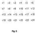
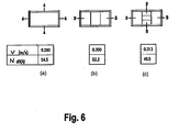
- FIG. 6 shows a diagram in which the average velocity v of the Air flow and the noise level N of a fan system of the present here Invention compared with the values without the present invention become.
- the average velocity v of the air flow is at 24 different points measured in the installation of the fan, as illustrated in FIG.
- Fig. 6 (a) is a conventional fan unit whereas Figures 6 (b) and 6 (c) are here shown present invention.
- the average speed v of Air at both 6 (b) and 6 (c) is higher, and the noise level is N. lower than in 6 (a).
- the pressure loss of the fan systems. 6 (b) and 6 (c) smaller than in Fig. 6 (a). That's why energy savings can be made with the Time to be achieved.
- the noise level becomes N in Decibels from a fan unit of the preferred form present here Invention compared with a non-preferred form, and is at measured a spot 1.5 meters below the outlet of the plant.
- the Fan system can be operated with less noise than a fan system according to the prior art.
Landscapes
- Engineering & Computer Science (AREA)
- Mechanical Engineering (AREA)
- General Engineering & Computer Science (AREA)
- Structures Of Non-Positive Displacement Pumps (AREA)
Abstract
Description
Der Erfindung liegt die Aufgabe zugrunde, Ventilator-Anlagen der eingangs genannten Art bereit zu stellen, bei welchem die genannten Nachteile nicht mehr auftreten.
- ein Kopfteil mit einer Einlassöffnung,
- mindestens eine Seite, die die Ventilator-Anlage umschließt,
- eine Auslassöffnung,
- ein auf einem Gebläse-Gestell sitzendes Windradgebläse, wobei das Windradgebläse dem Einblasen von Luft durch die Einlassöffnung und dem Ausstoßen von Luft durch die Auslassöffnung dient,
- mindestens ein Paar Leitstangen, die sich von einem niedrigeren Ende von mindestens einer Seite zur Auslassöffnung nach innen erstrecken, wobei das genannte Paar Leitstangen und das Gebläse-Gestell einen dazwischen liegenden Luftstromkanal bilden. Der Luftstromkanal bildet eine Verengung des Luftstromes, um den Luftdruck innerhalb des Luftstromkanals anzuheben und dadurch im Wesentlichen einen Luftstrom mit reduzierter Turbulenz in einer Richtung im Luftstromkanal und durch die Auslassöffnung zu schaffen, so dass der Lärm aus besagter Ventilator-Anlage abgeschwächt wird.
- Figur 1:
- Eine perspektivische Vorderansicht in aufgelösten Einzelteilen einer bevorzugten Form der hier vorliegenden, als Teil einer Ventilator-Anlage ausgebildeten Erfindung.
- Figur 2:
- Ein erhöhter Querschnitt der Anordnung gemäß Figur 1 beim Einbau.
- Figur 3:
- Ein vollständiger Querschnitt längs den Geraden A-A und entlang der Richtung der Pfeile A-A gemäß Figur 2.
- Figur 4:
- Eine der Figur 3 entsprechende Ansicht einer alternativen Ausführungsform.
- Figur 5:
- Darstellung der Orte, wo die Geschwindigkeit des Luftstromes gemessen wurde.
- Figur 6:
- Ein Diagramm mit dem Vergleich der durchschnittlichen Geschwindigkeit des Luftstromes und dem Geräuschpegel der bevorzugten Form der hier vorliegenden Erfindung mit den Werten der nicht bevorzugten Form.
- Figur 7:
- Ein erhöhter Querschnitt einer alternativen Ausführungsform Verkörperung des unteren Teils der zusammengebauten Anordnung gemäß Figur 1.
- (1)
- Einlass-Luftstrom
- (2)
- Auslass-Luftstrom
- (3)
- Interner Luftstrom
- (6)
- Isoliermaterial
- (10)
- Mittige Öffnung
- (11)
- Lufteinlass-Abdeckung
- (12)
- Gebläse
- (13)
- Stangen
- (14)
- Gebläse-Gestell
- (15)
- Seiten von 14
- (16)
- Isoliermaterial
- (17)
- Kopfteil
- (18)
- Lufteinlassöffnung
- (19)
- Luftauslassöffnung
- (20)
- Luftstromkanäle
- (22)
- Seitenwände
- (26)
- Platten
- (28)
- Leit-Ablenkplatten
- (31)
- Zwischenraum hinter 26
- (32)
- Filter
- (36)
- Isoliermaterial
Claims (30)
- Ventilator-Anlage umfassend:ein Kopfteil mit einer Einlassöffnung,mindestens eine Seite, die die Ventilator-Anlage umschließt,eine Auslassöffnung,ein auf einem Gestell sitzendes Windradgebläse, wobei das Windradgebläse dem Einblasen von Luft durch die Einlassöffnung und dem Ausstoßen von Luft durch die Auslassöffnung dient,mindestens ein Paar Leit-Ablenkplatten, die sich von einem niedrigeren Ende der wenigstens einen Seite zur Auslassöffnung nach innen erstrecken, wobei zwischen dem mindestens einen Paar Leit-Ablenkplatten und dem Gestell ein Luftstromkanal gebildet ist, der eine Verengung des Luftstromes erzeugt, um den Luftdruck innerhalb des Luftstromkanals anzuheben und dadurch einen im Wesentlichen gerichteten Luftstrom mit reduzierter Turbulenz im Luftstromkanal und durch die Auslassöffnung zu erzeugen, so dass der Lärm aus besagter Ventilator-Anlage abgeschwächt ist.
- Ventilator-Anlage nach Anspruch 1, dadurch gekennzeichnet, dass das Gestell ein Gebläse-Gestell ist.
- Ventilator-Anlage nach Anspruch 1 oder 2, dadurch gekennzeichnet, dass zwei Paare Leit-Ablenkplatten innerhalb der Ventilator-Anlage angebracht sind, wobei die Leit-Ablenkplatten jeweils senkrecht stehen.
- Ventilator-Anlage nach Anspruch 3, dadurch gekennzeichnet, dass die Leit-Ablenkplatten die Auslassöffnung festlegen.
- Ventilator-Anlage nach einem der Ansprüche 1 bis 4, dadurch gekennzeichnet, dass die Leit-Ablenkplatten in einem Winkel zwischen 90° und 60° zu wenigstens einer Seite angeordnet sind.
- Ventilator-Anlage nach Anspruch 5, dadurch gekennzeichnet, dass der Winkel 90° beträgt.
- Ventilator-Anlage nach einem der Ansprüche 1 bis 6, dadurch gekennzeichnet, dass die Leit-Ablenkplatten perforiert sind.
- Ventilator-Anlage nach Anspruch 7, dadurch gekennzeichnet, dass sich die Perforationen nur über einen Teil der Leit-Ablenkplatten erstrecken.
- Ventilator-Anlage nach Anspruch 7, dadurch gekennzeichnet, dass sich die Perforationen über die gesamten Leit-Ablenkplatten erstrecken.
- Ventilator-Anlage nach Anspruch 8 oder 9, dadurch gekennzeichnet, dass die Perforationen von einem Tuch abgedeckt sind.
- Ventilator-Anlage nach einem der Ansprüche 1 bis 10, dadurch gekennzeichnet, dass die Auslassöffnung kreisförmig, dreieckig, viereckig, rechteckig, fünfeckig oder achteckig ausgebildet ist.
- Ventilator-Anlage nach einem der Ansprüche 1 bis 11, dadurch gekennzeichnet, dass die Leit-Ablenkplatten gekrümmt sind.
- Ventilator-Anlage nach einem der Ansprüche 1 bis 12, dadurch gekennzeichnet, dass diese mindestens ein Paar Platten aufweist, die in der Ventilator-Anlage angebracht sind und sich zwischen dem Kopfteil und mindestens einer Seite erstrecken, wobei jedes von dem mindestens einem Paar Platten einen geschlossenen Zwischenraum zwischen jedem von mindestens einem Paar Platten, dem Kopfteil und mindestens einer Seite festlegt.
- Ventilator-Anlage nach Anspruch 13, dadurch gekennzeichnet, dass die Platten in einem Winkel zwischen 30° und 60° zu dem Kopfteil stehen.
- Ventilator-Anlage nach Anspruch 14, dadurch gekennzeichnet, dass der Winkel 45° beträgt.
- Ventilator-Anlage nach einem der Ansprüche 13 bis 15, dadurch gekennzeichnet, dass zwei Paare Platten vorhanden sind und die Platten jeweils senkrecht stehen.
- Ventilator-Anlage nach einem der Ansprüche 13 bis 16, dadurch gekennzeichnet, dass mindestens ein Paar Platten perforiert ist.
- Ventilator-Anlage nach Anspruch 17, dadurch gekennzeichnet, dass die Perforationen sich über die gesamtem Platten des mindestens einen Paares erstrecken.
- Ventilator-Anlage nach Anspruch 17, dadurch gekennzeichnet, dass die Perforationen sich nur über einen Teil der Platten des mindestens einen Paares erstrecken.
- Ventilator-Anlage nach einem der Ansprüche 17 bis 19, dadurch gekennzeichnet, dass die Perforationen von einem Tuch bedeckt sind.
- Ventilator-Anlage nach einem der Ansprüche 13 bis 20, dadurch gekennzeichnet, dass die Platten gekrümmt sind.
- Ventilator-Anlage einem der Ansprüche 13 bis 21, dadurch gekennzeichnet, dass der geschlossene Zwischenraum mindestens teilweise mit Lärm-Isoliermaterial gefüllt ist.
- Ventilator-Anlage nach einem der Ansprüche 1 bis 22, dadurch gekennzeichnet, dass ein Lärm-Isoliermaterial benutzt wird, um eine Innenfläche von einem oder mehreren der folgenden Teile zu verkleiden: mindestens eine Seite, Kopfteil, Leit-Ablenkplatten und Platten.
- Ventilator-Anlage nach einem der Ansprüche 1 bis 23, dadurch gekennzeichnet, dass an die Oberfläche des Gebläse-Gestells ein Lärm-Isoliermaterial angebracht ist.
- Ventilator-Anlage nach einem der Ansprüche 1 bis 24, dadurch gekennzeichnet, dass das Gebläse-Gestell die Form eines Innenbodens mit damit zusammenhängenden Seitenwänden aufweist, und dass sich das Lärm-Isoliermaterial im Boden befindet.
- Ventilator-Anlage nach einem der Ansprüche 1 bis 25, dadurch gekennzeichnet, dass das Kopfteil eine mittige Öffnung aufweist, welche über eine Einlassabdeckung verfügt, wobei die Einlassöffnung sich in der Einlassabdeckung befindet.
- Ventilator-Anlage nach einem der Ansprüche 1 bis 26, dadurch gekennzeichnet, dass diese einen unterhalb der Auslassöffnung angebrachten Filter aufweist.
- Ventilator-Anlage nach einem der Ansprüche 1 bis 27, dadurch gekennzeichnet, dass mindestens eine Seite vier jeweils senkrechte Seitenwände umfasst, und dass die Seitenwände jeweils auch senkrecht zum Kopfteil angeordnet sind.
- Ventilator-Anlage nach einem der Ansprüche 1 bis 28, dadurch gekennzeichnet, dass die in der Ventilator-Anlage verwendeten Ablenkplatten als Streu-Ablenkplatten oder Leit-Ablenkplatten ausgebildet sind.
- Verfahren zur Regelung des Luftstromes unter Verwendung einer Ventilator-Anlage umfassend:ein Kopfteil mit einer Einlassöffimng,mindestens eine Seite zum Umschließen der Ventilator-Anlage,eine Auslassöffnung,ein auf einem Gebläse-Gestell angebrachtes Windradgebläse, wobei das Windradgebläse die Funktion hat, Luft durch die Einlassöffnung einzublasen und Luft durch die Auslassöffnung auszustoßen,mindestens ein Paar Leitstangen, die sich nach innen von einem niedrigeren Ende der wenigstens einen Seite zur Auslassöffnung erstrecken, wobei zwischen dem mindestens einem Paar Leitstangen und dem Gebläse-Gestell ein Luftstromkanal gebildet wird, und der Luftstromkanal eine Verengung des Luftstromes zur Erhöhung des Luftdrucks innerhalb des Luftstroms erzeugt, um im Wesentlichen einen Luftstrom in einer Richtung und mit reduzierter Turbulenz im Luftstromkanal und durch die Auslassöffnung zu schaffen, so dass der Lärm in der besagten Ventilator-Anlage abgeschwächt wird.
Applications Claiming Priority (2)
| Application Number | Priority Date | Filing Date | Title |
|---|---|---|---|
| SG200306562-0A SG142128A1 (en) | 2003-11-05 | 2003-11-05 | Fan unit air flow control |
| SG200306562 | 2003-11-05 |
Publications (3)
| Publication Number | Publication Date |
|---|---|
| EP1530109A2 true EP1530109A2 (de) | 2005-05-11 |
| EP1530109A3 EP1530109A3 (de) | 2006-01-18 |
| EP1530109B1 EP1530109B1 (de) | 2008-03-12 |
Family
ID=34432639
Family Applications (1)
| Application Number | Title | Priority Date | Filing Date |
|---|---|---|---|
| EP04017423A Expired - Lifetime EP1530109B1 (de) | 2003-11-05 | 2004-07-23 | Ventilator-Anlage und Verfahren zur Regelung des Luftstroms einer Ventilator-Anlage |
Country Status (5)
| Country | Link |
|---|---|
| US (1) | US20050092544A1 (de) |
| EP (1) | EP1530109B1 (de) |
| CN (1) | CN1614243A (de) |
| DE (1) | DE502004006474D1 (de) |
| SG (1) | SG142128A1 (de) |
Families Citing this family (12)
| Publication number | Priority date | Publication date | Assignee | Title |
|---|---|---|---|---|
| USD575382S1 (en) * | 2007-04-19 | 2008-08-19 | Frank Hammes | Air flow cabinet |
| US20100112929A1 (en) * | 2008-11-03 | 2010-05-06 | Airex Inc. | Recessed fan inlet cover |
| EP2557908B1 (de) * | 2011-05-16 | 2018-07-18 | Huawei Technologies Co., Ltd. | Wärmeunterdrücker und aussenkommunikationsvorrichtung |
| US8899378B2 (en) | 2011-09-13 | 2014-12-02 | Black & Decker Inc. | Compressor intake muffler and filter |
| AU2012216660B2 (en) | 2011-09-13 | 2016-10-13 | Black & Decker Inc | Tank dampening device |
| US11111913B2 (en) | 2015-10-07 | 2021-09-07 | Black & Decker Inc. | Oil lubricated compressor |
| JP6134407B2 (ja) * | 2016-02-24 | 2017-05-24 | ミネベアミツミ株式会社 | 遠心式ファン |
| DE102016226157A1 (de) * | 2016-12-23 | 2018-06-28 | Ziehl-Abegg Se | Ventilatormodul sowie Anordnung eines oder mehrerer solcher Ventilatormodule in einem Strömungskanal |
| CN108906795B (zh) * | 2018-08-21 | 2024-04-02 | 镇江裕太防爆电加热器有限公司 | 一种用于三角形镁管烧结设备的吹扫结构 |
| CN111984090A (zh) * | 2020-09-28 | 2020-11-24 | 苏州浪潮智能科技有限公司 | 一种风扇挡板、风扇模组及机箱 |
| CN112957833A (zh) * | 2021-03-10 | 2021-06-15 | 惠亚科技(苏州)有限公司 | 一种过滤设备 |
| CN113202262B (zh) * | 2021-05-25 | 2022-09-09 | 浙江宁溢电力工程设计咨询有限公司 | 一种地下变电所的通风装置 |
Family Cites Families (10)
| Publication number | Priority date | Publication date | Assignee | Title |
|---|---|---|---|---|
| US3085647A (en) * | 1960-11-07 | 1963-04-16 | Jenn Air Products Company Inc | Acoustic curb |
| US4560395A (en) * | 1984-04-17 | 1985-12-24 | Environmental Air Control, Inc. | Compact blower and filter assemblies for use in clean air environments |
| US4990290A (en) * | 1989-05-08 | 1991-02-05 | Gill James G | Diffusion fogger |
| DE4412583C1 (de) * | 1994-04-13 | 1995-09-14 | Daldrop & Dr Ing Huber Gmbh & | Ventilator-Filtereinheit für Reinraumdecken |
| US5470363A (en) * | 1995-01-13 | 1995-11-28 | Envirco Corporation | Air blower and filter assemblies |
| US5801342A (en) * | 1997-01-27 | 1998-09-01 | Lindab Ab | Double-walled structure and method and arrangement for producing the same |
| WO1999011984A1 (en) * | 1997-09-03 | 1999-03-11 | Kyodo-Allied Industries Ltd. | A method and apparatus for minimising noise from fan filter unit |
| US6217281B1 (en) * | 1999-06-30 | 2001-04-17 | Industrial Technology Research Institute | Low-noise fan-filter unit |
| US6592451B2 (en) * | 2001-02-26 | 2003-07-15 | Kyodo-Allied Industries Ltd | Fan unit |
| US6444004B1 (en) * | 2001-02-26 | 2002-09-03 | Kyodo-Allied Industries Ltd. | Fan unit |
-
2003
- 2003-11-05 SG SG200306562-0A patent/SG142128A1/en unknown
-
2004
- 2004-06-25 US US10/877,632 patent/US20050092544A1/en not_active Abandoned
- 2004-07-23 EP EP04017423A patent/EP1530109B1/de not_active Expired - Lifetime
- 2004-07-23 DE DE502004006474T patent/DE502004006474D1/de not_active Expired - Lifetime
- 2004-09-03 CN CNA2004100742347A patent/CN1614243A/zh active Pending
Also Published As
| Publication number | Publication date |
|---|---|
| US20050092544A1 (en) | 2005-05-05 |
| SG142128A1 (en) | 2008-05-28 |
| DE502004006474D1 (de) | 2008-04-24 |
| EP1530109A3 (de) | 2006-01-18 |
| EP1530109B1 (de) | 2008-03-12 |
| CN1614243A (zh) | 2005-05-11 |
Similar Documents
| Publication | Publication Date | Title |
|---|---|---|
| EP0497296B1 (de) | Filter-Ventilator-Einrichtung zur Verwendung bei Reinräumen | |
| DE102008012664A1 (de) | Windenergieanlage und ein Turm oder Turmsegment und eine Türzarge dafür | |
| DE19849035C2 (de) | Schallabsorptionsvorrichtung und Vorrichtung zum Zuführen von Luft in den Motorraum einer Baumaschine | |
| EP1530109B1 (de) | Ventilator-Anlage und Verfahren zur Regelung des Luftstroms einer Ventilator-Anlage | |
| DE2941276A1 (de) | Stroemungsverteilungsvorrichtung und ein mit einer solchen vorrichtung versehenes lufteintrittsgitter | |
| CH643984A5 (de) | Behandlungskammer zur behandlung von tieren, pflanzen oder materialien mittels luft, der andere gase oder aerosole beigemischt sind. | |
| DE4008012C2 (de) | Lüftungsanordnung für ein einen Gefrierraum und einen Kühlraum aufweisendes Kühlgerät | |
| EP2937015A1 (de) | Arbeitstisch | |
| DE60209160T2 (de) | Hangar zum Hochfahren von Flugzeugtriebwerken | |
| DE2156189C2 (de) | Dachentlüfter | |
| DE102011018962C5 (de) | Kochfeld mit zentraler Absaugung von Kochdünsten nach unten | |
| DE69207056T2 (de) | Verfahren und Vorrichtung für die Belüftung eines Behandlungsraumes | |
| DE1154252B (de) | Abschirmung von Raumoeffnungen durch einen Luftschleier | |
| DE3537671A1 (de) | Vorrichtung zum befeuchten, reinigen und kuehlen von gasen | |
| DE69108015T2 (de) | Tragbares hochdruckreinigungsgerät. | |
| DE10005964C2 (de) | Vorrichtung zum Verhindern des Eindringens von Zugluft durch eine Öffnung in einem Gebäude | |
| EP2613096B1 (de) | Haushalts-Dunstabzug mit vier parallelen Filterplatten | |
| EP0043504B1 (de) | Aussenwandkasten für die Verbrennungsluft- und Abgaskanäle eines mit einem Brennersystem arbeitenden Gerätes | |
| EP1695422A1 (de) | Schrankartiges gehäuse mit luftkühlung | |
| DE202008010063U1 (de) | Lufttechnische Einrichtung | |
| DE3914242A1 (de) | Einrichtung zum erwaermen und/oder kuehlen von raeumen | |
| DE102013111244A1 (de) | Luftauslass | |
| DE3940277C1 (en) | Sound damping structure - has silencer body with acoustic lining and contg. profiled and absorber | |
| DE4341784A1 (de) | Anordnung zur Erzeugung zweier gegenläufiger Luftschleier | |
| DE4103026C1 (de) |
Legal Events
| Date | Code | Title | Description |
|---|---|---|---|
| PUAI | Public reference made under article 153(3) epc to a published international application that has entered the european phase |
Free format text: ORIGINAL CODE: 0009012 |
|
| AK | Designated contracting states |
Kind code of ref document: A2 Designated state(s): AT BE BG CH CY CZ DE DK EE ES FI FR GB GR HU IE IT LI LU MC NL PL PT RO SE SI SK TR |
|
| AX | Request for extension of the european patent |
Extension state: AL HR LT LV MK |
|
| PUAL | Search report despatched |
Free format text: ORIGINAL CODE: 0009013 |
|
| AK | Designated contracting states |
Kind code of ref document: A3 Designated state(s): AT BE BG CH CY CZ DE DK EE ES FI FR GB GR HU IE IT LI LU MC NL PL PT RO SE SI SK TR |
|
| AX | Request for extension of the european patent |
Extension state: AL HR LT LV MK |
|
| RIC1 | Information provided on ipc code assigned before grant |
Ipc: F04D 29/66 20060101ALI20051125BHEP Ipc: F04D 29/42 20060101AFI20051125BHEP |
|
| 17P | Request for examination filed |
Effective date: 20060208 |
|
| AKX | Designation fees paid |
Designated state(s): DE GB |
|
| GRAP | Despatch of communication of intention to grant a patent |
Free format text: ORIGINAL CODE: EPIDOSNIGR1 |
|
| GRAS | Grant fee paid |
Free format text: ORIGINAL CODE: EPIDOSNIGR3 |
|
| GRAA | (expected) grant |
Free format text: ORIGINAL CODE: 0009210 |
|
| AK | Designated contracting states |
Kind code of ref document: B1 Designated state(s): DE GB |
|
| REG | Reference to a national code |
Ref country code: GB Ref legal event code: FG4D Free format text: NOT ENGLISH |
|
| REF | Corresponds to: |
Ref document number: 502004006474 Country of ref document: DE Date of ref document: 20080424 Kind code of ref document: P |
|
| PLBE | No opposition filed within time limit |
Free format text: ORIGINAL CODE: 0009261 |
|
| STAA | Information on the status of an ep patent application or granted ep patent |
Free format text: STATUS: NO OPPOSITION FILED WITHIN TIME LIMIT |
|
| 26N | No opposition filed |
Effective date: 20081215 |
|
| PGFP | Annual fee paid to national office [announced via postgrant information from national office to epo] |
Ref country code: DE Payment date: 20110804 Year of fee payment: 8 Ref country code: GB Payment date: 20110721 Year of fee payment: 8 |
|
| GBPC | Gb: european patent ceased through non-payment of renewal fee |
Effective date: 20120723 |
|
| PG25 | Lapsed in a contracting state [announced via postgrant information from national office to epo] |
Ref country code: DE Free format text: LAPSE BECAUSE OF NON-PAYMENT OF DUE FEES Effective date: 20130201 Ref country code: GB Free format text: LAPSE BECAUSE OF NON-PAYMENT OF DUE FEES Effective date: 20120723 |
|
| REG | Reference to a national code |
Ref country code: DE Ref legal event code: R119 Ref document number: 502004006474 Country of ref document: DE Effective date: 20130201 |