EP1529855A2 - Diffusionssystem - Google Patents
Diffusionssystem Download PDFInfo
- Publication number
- EP1529855A2 EP1529855A2 EP04255090A EP04255090A EP1529855A2 EP 1529855 A2 EP1529855 A2 EP 1529855A2 EP 04255090 A EP04255090 A EP 04255090A EP 04255090 A EP04255090 A EP 04255090A EP 1529855 A2 EP1529855 A2 EP 1529855A2
- Authority
- EP
- European Patent Office
- Prior art keywords
- gas
- main chamber
- premixer
- tube
- exhausting
- Prior art date
- Legal status (The legal status is an assumption and is not a legal conclusion. Google has not performed a legal analysis and makes no representation as to the accuracy of the status listed.)
- Granted
Links
Images


Classifications
-
- C—CHEMISTRY; METALLURGY
- C30—CRYSTAL GROWTH
- C30B—SINGLE-CRYSTAL GROWTH; UNIDIRECTIONAL SOLIDIFICATION OF EUTECTIC MATERIAL OR UNIDIRECTIONAL DEMIXING OF EUTECTOID MATERIAL; REFINING BY ZONE-MELTING OF MATERIAL; PRODUCTION OF A HOMOGENEOUS POLYCRYSTALLINE MATERIAL WITH DEFINED STRUCTURE; SINGLE CRYSTALS OR HOMOGENEOUS POLYCRYSTALLINE MATERIAL WITH DEFINED STRUCTURE; AFTER-TREATMENT OF SINGLE CRYSTALS OR A HOMOGENEOUS POLYCRYSTALLINE MATERIAL WITH DEFINED STRUCTURE; APPARATUS THEREFOR
- C30B31/00—Diffusion or doping processes for single crystals or homogeneous polycrystalline material with defined structure; Apparatus therefor
- C30B31/06—Diffusion or doping processes for single crystals or homogeneous polycrystalline material with defined structure; Apparatus therefor by contacting with diffusion material in the gaseous state
- C30B31/10—Reaction chambers; Selection of materials therefor
-
- C—CHEMISTRY; METALLURGY
- C23—COATING METALLIC MATERIAL; COATING MATERIAL WITH METALLIC MATERIAL; CHEMICAL SURFACE TREATMENT; DIFFUSION TREATMENT OF METALLIC MATERIAL; COATING BY VACUUM EVAPORATION, BY SPUTTERING, BY ION IMPLANTATION OR BY CHEMICAL VAPOUR DEPOSITION, IN GENERAL; INHIBITING CORROSION OF METALLIC MATERIAL OR INCRUSTATION IN GENERAL
- C23C—COATING METALLIC MATERIAL; COATING MATERIAL WITH METALLIC MATERIAL; SURFACE TREATMENT OF METALLIC MATERIAL BY DIFFUSION INTO THE SURFACE, BY CHEMICAL CONVERSION OR SUBSTITUTION; COATING BY VACUUM EVAPORATION, BY SPUTTERING, BY ION IMPLANTATION OR BY CHEMICAL VAPOUR DEPOSITION, IN GENERAL
- C23C8/00—Solid state diffusion of only non-metal elements into metallic material surfaces; Chemical surface treatment of metallic material by reaction of the surface with a reactive gas, leaving reaction products of surface material in the coating, e.g. conversion coatings, passivation of metals
- C23C8/06—Solid state diffusion of only non-metal elements into metallic material surfaces; Chemical surface treatment of metallic material by reaction of the surface with a reactive gas, leaving reaction products of surface material in the coating, e.g. conversion coatings, passivation of metals using gases
-
- C—CHEMISTRY; METALLURGY
- C30—CRYSTAL GROWTH
- C30B—SINGLE-CRYSTAL GROWTH; UNIDIRECTIONAL SOLIDIFICATION OF EUTECTIC MATERIAL OR UNIDIRECTIONAL DEMIXING OF EUTECTOID MATERIAL; REFINING BY ZONE-MELTING OF MATERIAL; PRODUCTION OF A HOMOGENEOUS POLYCRYSTALLINE MATERIAL WITH DEFINED STRUCTURE; SINGLE CRYSTALS OR HOMOGENEOUS POLYCRYSTALLINE MATERIAL WITH DEFINED STRUCTURE; AFTER-TREATMENT OF SINGLE CRYSTALS OR A HOMOGENEOUS POLYCRYSTALLINE MATERIAL WITH DEFINED STRUCTURE; APPARATUS THEREFOR
- C30B31/00—Diffusion or doping processes for single crystals or homogeneous polycrystalline material with defined structure; Apparatus therefor
- C30B31/06—Diffusion or doping processes for single crystals or homogeneous polycrystalline material with defined structure; Apparatus therefor by contacting with diffusion material in the gaseous state
-
- C—CHEMISTRY; METALLURGY
- C30—CRYSTAL GROWTH
- C30B—SINGLE-CRYSTAL GROWTH; UNIDIRECTIONAL SOLIDIFICATION OF EUTECTIC MATERIAL OR UNIDIRECTIONAL DEMIXING OF EUTECTOID MATERIAL; REFINING BY ZONE-MELTING OF MATERIAL; PRODUCTION OF A HOMOGENEOUS POLYCRYSTALLINE MATERIAL WITH DEFINED STRUCTURE; SINGLE CRYSTALS OR HOMOGENEOUS POLYCRYSTALLINE MATERIAL WITH DEFINED STRUCTURE; AFTER-TREATMENT OF SINGLE CRYSTALS OR A HOMOGENEOUS POLYCRYSTALLINE MATERIAL WITH DEFINED STRUCTURE; APPARATUS THEREFOR
- C30B31/00—Diffusion or doping processes for single crystals or homogeneous polycrystalline material with defined structure; Apparatus therefor
- C30B31/06—Diffusion or doping processes for single crystals or homogeneous polycrystalline material with defined structure; Apparatus therefor by contacting with diffusion material in the gaseous state
- C30B31/16—Feed and outlet means for the gases; Modifying the flow of the gases
- C30B31/165—Diffusion sources
-
- C—CHEMISTRY; METALLURGY
- C30—CRYSTAL GROWTH
- C30B—SINGLE-CRYSTAL GROWTH; UNIDIRECTIONAL SOLIDIFICATION OF EUTECTIC MATERIAL OR UNIDIRECTIONAL DEMIXING OF EUTECTOID MATERIAL; REFINING BY ZONE-MELTING OF MATERIAL; PRODUCTION OF A HOMOGENEOUS POLYCRYSTALLINE MATERIAL WITH DEFINED STRUCTURE; SINGLE CRYSTALS OR HOMOGENEOUS POLYCRYSTALLINE MATERIAL WITH DEFINED STRUCTURE; AFTER-TREATMENT OF SINGLE CRYSTALS OR A HOMOGENEOUS POLYCRYSTALLINE MATERIAL WITH DEFINED STRUCTURE; APPARATUS THEREFOR
- C30B35/00—Apparatus not otherwise provided for, specially adapted for the growth, production or after-treatment of single crystals or of a homogeneous polycrystalline material with defined structure
Definitions
- the present invention relates to a diffusion system, and more particularly, to a diffusion system for forming an ultrathin doping layer in a wafer.
- the diffusion system uniformizes the concentration of a mixed gas for forming the doping layer in a short amount of time, includes a cooling rate controller for securing a high frequency response, and provides a flow system for allowing a stable gas flow.
- a material doped into a semiconductor device is selected in consideration of a diffusion coefficient, a solid-solubility characteristic, a mask effect of an oxide layer, and the like. Even if combined atoms are separated from a doping material during a diffusion process, the atoms must not act as another dopant atoms that may be doped into a wafer or produce an unetchable material on the wafer.
- a material that is doped into a wafer should have few impurities, and the concentration of the material should be easily controlled at a constant level in spite of repeated processes.
- a doping material remains combined with oxygen, hydrogen, or halogens such as chlorine or bromine and is categorized into a solid, a liquid, and a gas.
- a diffusion system includes a diffusion tube, a heater, a boat, and a dopant delivery system.
- the diffusion system can be categorized into a sealed-tube system, an open-tube system, a box-type system, a paint-on system, and a rapid thermal processing system.
- a conventional diffusion system lacks high frequency response and robust characteristics against external disturbances, which are required to form an ultrathin doping layer with a thickness of 100 nm or less, namely, a doping layer for diffusing thermal energy.
- the diffusion system requires a high frequency response characteristic so that the concentration of a gas mixture can be rapidly uniformized and the speed with which a wafer that has undergone a doping process is cooled can be finely adjusted.
- a flow system and respective apparatuses should be closely connected to one another so as to stably supply a gas mixture and exhaust a used gas.
- the conventional diffusion system cannot systemically fulfill the foregoing requirements.
- a diffusion system for forming a doping layer in a wafer.
- the diffusion system comprises a bubbler that generates a doping gas; a premixer that premixes the doping gas with reactive gases and preheats the gas mixture; a main chamber, in which the gas mixture reacts to the wafer; a buffer case that externally isolates an exhaust port and a door for loading and unloading the wafer into and out of the main chamber; and a used gas exhaustion system that exhausts a used gas after the reaction is finished in the main chamber.
- the bubbler may include a container that contains a doping material; an absorbing tube that absorbs a carrier gas for carrying the doping gas; a carrier tube that carries the doping gas for carrying the doping material carried by the carrier gas; a pressure regulator that measures the pressure of the container and regulates the pressure of the container to a predetermined value; and a bypass tube that exhausts gases contained in the bubbler using a bypass valve when the pressure of the bubbler exceeds a predetermined value.
- the premixer may include a premixer container; one or more gas carrier tubes that carry the doping gas and the reactive gases; a gas mixture supply tube that supplies the gas mixture from the premixer container to the main chamber; and a heater that controls the temperature of the premixer.
- the gas carrier tubes may extend into the premixer container to spray gases.
- a portion of the premixer container, which exhausts the gas mixture to the gas mixture supply tube, may have a tapering or conic shape to prevent a whirl in corners of the premixer container.
- the diameter of the gas mixture supply tube may be 1. 7 times or more greater than the diameter of each of the gas carrier tubes.
- the main chamber may include an atmospheric gas nozzle that is formed on one side of the main chamber and sprays an atmospheric gas; a gas mixture nozzle that sprays a gas mixture containing a doping gas in an opposite direction to a direction in which the atmospheric gas nozzle sprays the atmospheric gas such that the atmospheric gas is mixed with the doping gas; the door, via which the wafer is loaded in and unloaded from the main chamber; and the exhaust port that exhausts a remaining used gas after the doping gas reacts to the wafer.
- the gas mixture nozzle may be a back nozzle formed at a terminal portion of the gas mixture supply tube that extends from the premixer into the main chamber.
- the diffusion system may further include a reactive gas tube that is connected to one side of an atmospheric gas tube, which is connected to the atmospheric gas nozzle and supplies the atmospheric gas to the main chamber, and supplies a reactive gas to the atmospheric gas tube.
- the door may have a double insulation structure formed of quartz and graphite, which are sequentially stacked.
- the buffer case may hermetically seal the door and the exhaust port of the main chamber, and a shower nozzle for spraying a cooling gas may be formed at an exhausting tube connected to the door and the exhaust port.
- the waste gas exhausting system may include a supporting system that prevents a sag in the exhausting tube due to the high-temperature waste gas; and a scrubber that finally exhausts the waste gas.
- the supporting system may include a spring that supports the exhausting tube in a radial direction to prevent a sag in the exhausting tube due to thermal expansion; and a bellows that corrects thermal expansion of the exhausting tube in an axial direction and cools the waste gas with an increased surface area.
- a premixer for supplying a gas mixture containing a doping gas to a main chamber in which the gas mixture reacts to a wafer.
- the premixer includes a premixer container; one or more gas carrier tubes that receive the doping gas and reactive gases; a gas mixture supply tube that supplies the gas mixture from the premixer container to the main chamber; and a premixer heater that controls the temperature of the premixer.
- a main chamber of a diffusion system in which a wafer reacts to gases.
- the main chamber may include an atmospheric gas nozzle that is formed on one side of the main chamber and sprays an atmospheric gas; a gas mixture nozzle that sprays a gas mixture containing a doping gas in an opposite direction to a direction in which the atmospheric gas nozzle sprays the atmospheric gas such that the atmospheric gas is mixed with the doping gas; a door, via which the wafer is loaded into and unloaded from the main chamber; and an exhaust port that exhausts a remaining used gas after the doping gas reacts to the wafer.
- a waste gas exhausting system for exhausting a remaining waste gas from a main chamber after a wafer reacts to gases.
- the waste gas exhausting system comprises an exhausting tube, through which the waste gas flows to an exhaust port of the main chamber; a supporting system that prevents a sag in the exhausting tube due to the high-temperature waste gas and cooling the waste gas; and a scrubber finally that exhausts the waste gas using a vacuum pump connected to a terminal portion of the scrubber.
- the present invention thus provides a diffusion system which uniformizes the concentration of a gas mixture in a short amount of time, effectively controls the speed with which a wafer that has undergone a diffusion process is cooled, and stably exhausts a waste gas.
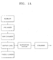
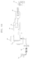
- a diffusion system includes a diffusion preprocessing portion, a main chamber 40, and a diffusion postprocessing portion.
- the diffusion preprocessing portion includes a bubbler 20, a premixer 30, and a back nozzle 35.
- the bubbler 20 generates a doping gas
- the premixer 30 premixes the generated doping gas at an appropriate temperature and preheats the same.
- the back nozzle 35 uniformly mixes the preheated gas with an atmospheric gas in the main chamber 40. Inside the main chamber 40, the doping gas is uniformly mixed with the atmospheric gas and reacts to a wafer, which is loaded in or unloaded from the main chamber 40 via a door 46 included in the main chamber 40.
- the diffusion postprocessing portion includes a buffer case 50, a supporting system 60, and a scrubber 70.
- the buffer case 50 cools the wafer and a waste gas exhausted from the main chamber 40 after a diffusion process.
- the supporting system 60 stably exhausts a high-temperature waste gas, and the scrubber 70 stably processes the waste gas. Accordingly, after the doping gas is generated and reacts to the wafer, the doping gas flows through the bubbler 20, the premixer 30, the back nozzle 35, the main chamber 40, and the buffer case 50, is exhausted through the supporting system 60 and the scrubber 70.
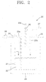
- FIG. 2 shows the bubbler 20 of the diffusion preprocessing portion described above.
- the bubbler 20 includes not only basic elements such as a mass flow controller (MFC) 28, an in-valve 24, and an out-valve 25, but also a bypass valve 26 and a pressure regulator 27.
- MFC mass flow controller
- the bubbler 20 of the diffusion system includes three tubes 23a, 23b, and 23c, which are connected to a container 21 for containing a doping material 22.
- the tubes 23a, 23b, and 23c are respectively an absorbing tube 23a, a carrier tube 23b, and an exhausting tube 23c.
- the absorbing tube 23a, to which the in-valve 24 is attached absorbs a carrier gas, such as nitrogen, and carries the carrier gas into the container 21.
- the carrier tube 23b allows the out-valve 21 to carry the doping material 22 from the container 21 to the premixer 30.
- the exhausting tube 23c allows the bypass valve 26 to exhaust the remaining gas from the container 21.
- the pressure regulator 27 is used to measure a pressure in the container 21 of the bubbler 20.
- the bubbler 20 of the diffusion system improves stability using a double measurement, which will now be described in detail.
- the pressure regulator measures the pressure, and an external controller (not shown) senses the pressure and electrically insulates the in-valve 24. If the pressure of the container 21 abruptly increases, a gas contained in the container 21 is mechanically exhausted by opening the bypass valve 23c, and then processed using the scrubber 70. This double measurement prevents an unexpected elevation of the pressure in the container 21.
- a reference exhausting pressure of the bypass valve 26 can be preset to a higher value than a reference pressure of the pressure regulator 27.
- the container 21 of the bubbler 20 is located within an isolation box 29 and isolated from an external connection.
- the gas flows through the out-valve 25 and the carrier tube 23b into the premixer 30.
- a distance between the bubbler 20 and the premixer 30 is preferred to be minimized to reduce a duct resistance, since the duct resistance is proportional to distance and inversely proportional to the third power of a radius of the duct.
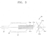
- FIG. 3 shows the premixer 30 of the diffusion system shown in FIG. 1B.
- the premixer 30 includes a supply tube 32 and a heater 34.
- the supply tube 32 supplies a gas to the carrier tube 23b connected to the bubbler 20 and the main chamber 40.
- the heater 34 controls the temperature of the premixer 30.
- the premixer 30 receives a gas to be used in the main chamber 40 from the bubbler 20, controls the gas to a predetermined temperature and composition, and carries the gas to the main chamber 40. Further, the heater 34 heats the gas to be supplied to the main chamber 40 as much as a process temperature of the main chamber 40.
- the premixer 30 of the diffusion system includes carrier tubes 31a, 31b, and 31c, which extend to the center of the premixer 30 so as to carry supply gases containing the gas carried by the bubbler 20 to the main chamber 40 without congestion.
- the carrier tubes 31a, 31b, and 31c each have more than 2.5 times the diameter of the supply tube 32 such that carried gases are exhausted through the supply tube 32 without congestion.
- a gas has to satisfy the minimum condition given in Equation 1.
- the mass flow rate of an input gas is equal to the mass flow rate of an output gas
- three tubes for carrying gases to the premixer 30 are installed including a tube for supplying a gas from the bubbler 20 to the premixer 30.
- 3 di 2 Do 2 wherein di is the diameter of each of the carrier tubes 31a, 31b, and 31c for carrying gases to the premixer 30, and Do is the diameter of the supply tube 32 for supplying a reactive gas to the main chamber. Accordingly, when the three carrier tubes 31a, 31b, and 31c and one supply tube 32 are used, Do should be about 1.7 times greater than di.
- the mass flow rates of gases that are respectively supplied from the carrier tubes 31a, 31b, and 31c are different from one another, Do should be 1.7 times or more greater than di and, more preferably, twice or more greater than di. Also, the carrier tubes 31a, 31b, and 31c can each have a far smaller diameter so as to prevent gases from flowing back.
- a portion 33 of a container of the premixer 30 near the supply tube 32 through which gases are exhausted from the premixer 30 to the main chamber is produced in a tapering or conic shape to prevent a whirl in corners of the container.
- a gas is supplied from the bubbler 20 through the premixer 30 to the main chamber without congestion.
- the gas is mixed with other gases in the premixer 30 until it reaches a predetermined temperature. Accordingly, although the size of the container of the premixer 30 should be controlled depending on a desired process, the container has preferably a small capacity.
- the gases carried from the bubbler 20 are mixed in the premixer 30 and react with each other. Then, the gas mixture is heated to nearly a process temperature of the main chamber by the heater 34 that surrounds the outer surface of the premixer 30. For example, if a process temperature in the main chamber is about 800 to 1100 °C, the premixer 30 is preheated to a temperature of about 500 to 800 °C. The process temperature is automatically controlled to a preset value by the controller.
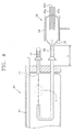
- FIG. 4 shows a connection portion between the premixer 30 and the main chamber 40 in the diffusion system shown in FIG. 1B.
- the supply tube 32 which supplies a reactive gas from the premixer 30 to the main chamber 40, includes a back nozzle 35 to uniformize the concentration of the reactive gas in the main chamber 40.
- a gas is supplied from the premixer 30 by the supply tube 32 and doped into a wafer loaded in the main chamber 40.
- a process time taken to expose the wafer to a gas mixture and the concentration of the gas mixture inside the main chamber 40 should be finely adjusted.
- a waste gas that remains in the main chamber 40 is exhausted, and the wafer is unloaded out of the main chamber 40 by a paddle loader used for carrying wafers.
- a paddle loader used for carrying wafers.
- an outlet of the supply tube 32 for allowing the gas mixture to flow from the premixer 30 into the main chamber 40 can face an outlet of an atmospheric gas nozzle 41 from which an atmospheric gas is sprayed, such that the gas mixture is mixed with the atmospheric gas.
- the atmospheric gas is sprayed from the atmospheric gas nozzle 41 across the gas mixture containing a doping material that is supplied from the supply tube 32.
- the concentration of the entire gas within the main chamber 40 can be uniformized in a short amount of time.
- the supply tube 32 includes the back nozzle 35, which serves to mix the gas that is heated and mixed by the premixer 30 with a main flow of the atmospheric gas.
- the back nozzle 35 allows the gas including the atmospheric gas in the main chamber 40 to steadily flow along a stream line of the main flow without disturbance in a short amount of time.
- the concentration of a gas in the chamber 40 is uniformized in a short amount of time, thereby forming an ultrathin doping layer having a thickness of 100 nm or less.
- the atmospheric gas is an inert gas, such as nitrogen or argon.
- another supply tube 42 is connected to a portion of an atmospheric gas tube that is connected to the atmospheric gas nozzle 41 as a precaution so as to supply a required gas along with the atmospheric gas.
- concentration of the gas mixture in the main chamber 40 can be controlled to a desired level.
- the back nozzle 35 of the supply tube 32 may not aligned to exactly face the atmospheric gas nozzle 41.
- a carrier line of the supply tube 32 may not be bent in the form of a duct within the main chamber 40.
- a direction in which the back nozzle 35 sprays a gas can be set relative to the atmospheric gas nozzle 41 such that the gas mixture forms a laminar flow in accordance with the flow of the inert gas.
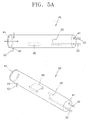
- FIG. 5A shows the main chamber 40 of the diffusion system shown in FIG. 1B.
- the back nozzle 35 for supplying a gas mixture is installed at one side of the main chamber 30, in which a reaction between the gas mixture and a wafer occurs, and an atmospheric gas nozzle 41 is installed at the one side of the main chamber 30, which faces the back nozzle 35.
- An atmospheric gas in the supply tube 32 flows through a portion of the back nozzle 35 and is supplied to the main chamber 40.
- a first door 44 is formed at a lateral surface of the main chamber 40.
- a wafer carrier 46 is loaded or unloaded via the first door 44 by a paddle loader (not shown).
- a wafer which reacts to the gas mixture having a controlled concentration, is mounted on the wafer carrier 46 and loaded into or unloaded out of the main chamber 40 by the paddle loader while the first door 44 is being opened or closed.
- An exhaust port 45 for exhausting a used gas is formed near the other side of the main chamber 40 at which the first door 44 is formed.
- the main chamber 40 includes a heater (43 of FIG. 4) for maintaining the main chamber 40 at a high temperature during reaction and a cooler (not shown) for cooling the main chamber 40.
- FIGS. 5B and 5C illustrate a process of supplying a gas mixture and an atmospheric gas to the main chamber 40 while uniformizing the concentration of gases in the main chamber 40.
- FIG. 5B shows a stream line of a gas in the main chamber 40
- FIG. 5C shows a concentration distribution of a gas mixture relative to time in the main chamber 40.
- FIG. 5B illustrates that a gas mixture is supplied from the premixer 30 and forms a laminar flow with an atmospheric gas over time in the main chamber 40.
- FIG. 5C illustrates a process of uniformizing the concentration of the gas mixture as the atmospheric gas is supplied.
- FIG. 5D is a graph showing a concentration variation of the gas mixture over time on a wafer in the main chamber 40. Referring to FIG. 5D, the gas mixture supplied from the premixer 30 to the main chamber 40 is uniformly distributed in less than about 80 seconds, and the distribution of the gas mixture over the wafer becomes uniform in about 40 seconds directly after supply of the gas mixture.
- the diffusion preprocessing portion including the bubbler 20, the premixer 30, and the back nozzle 35, as well as the main chamber 40 have been described with reference to the drawings.
- the diffusion postprocessing portion will be described.
- FIG. 6 shows a main chamber 40 and a buffer case 50 of a diffusion system according to the present invention.
- a gas mixture reacts to a wafer.
- the buffer case 50 hermetically seals the main chamber 40, and the wafer is loaded and unloaded via the buffer case 50.
- a first door 44 which allows a wafer carrier 46 to be loaded into or unloaded out of the man chamber 40, is formed at one side of the main chamber 40.
- the first door 44 which communicates the main chamber 40 with the buffer case 50 and carries the wafer carrier 46, has a double sandwich structure.
- This double sandwich structure can thermally insulate the buffer case 50 from the high-temperature main chamber 40 and is preferably formed of quartz and graphite, which are sequentially stacked. Quartz is highly resistant to melting at high temperature and graphite has a good thermal transmissivity.
- the lateral surface of the first door 44 is wrapped by glass fiber insulation, thereby thermally separating the buffer case 50 from the inside of the main chamber 40.
- the wafer carrier 46 including the wafer is unloaded from the main chamber 40 and then cooled by a shower nozzle 51.
- Another shower nozzle 51 is also installed near an exhaust port 45 to cool a high-temperature waste gas. This shower nozzle 51 cools the waste gas by spraying an inert gas such as nitrogen or argon.
- a second door 52 is formed in the buffer case 50 to carry the wafer unloaded from the main chamber 40 out of the buffer case 50.
- FIG. 7 shows a diffusion postprocessing portion for exhausting a waste gas in a diffusion system shown in FIG. 1B.
- the diffusion postprocessing portion of the diffusion system includes a shower nozzle 51, a supporting system 60, and a scrubber 70.
- the diffusion system of the present invention includes the shower nozzle 51.
- the waste gas is cooled by the buffer case 50 and enters the supporting system 60.
- the supporting system 60 of the present invention has a supporting structure for correcting thermal expansion in axial and radial directions of the exhausting tube 53.
- the waste gas which is exhausted from the main chamber 40 and passes through the exhausting tube 53 around the supporting system 60 may be maintained at about 400 to 500 °C. Accordingly, the exhausting tube 53 may thermally expand in axial and radial directions due to the high-temperature waste gas.
- elastic members such as springs, are attached to upper and lower portions of the exhausting tube 53 in the radial direction of the exhausting tube 53 so that the exhausting tube 53 is supported in a floating state by doubling an elastic coefficient.
- the hot waste gas is allowed to flow through a bellows 62, which supports the exhausting tube 53 in the axial direction of the exhausting tube 53 like a spring.
- the bellows 62 increases a contact area between the bellows 62 and the hot waste gas so as to improve cooling efficiency.
- the waste gas flows through the exhausting tube 53 and, finally, is exhausted through a pump installed at a terminal portion of the scrubber 70.
- An exhausting valve 71 and a pressure gauge 73 appropriately controls the flow rate of exhausted waste gas.
- a gas generated by a carrier gas (e.g., N 2 ) in the bubbler 20 is carried to the premixer 30 via the out-valve 25 under an appropriate pressure that is set up by the pressure regulator 27 and the bypass valve 26.
- a carrier gas e.g., N 2
- the gas carried from the bubbler 20 is mixed with oxygen (or a reactive gas such as CI) and heated to an appropriate temperature to minimize influence of a high temperature at which the main chamber is heated.
- oxygen or a reactive gas such as CI
- the gas which is mixed and heated in the premixer 30, is sprayed from the back nozzle 35 into the main chamber 40 and mixed with an atmospheric gas sprayed from the atmospheric gas nozzle 41.
- the gas in the main chamber 40 is uniformly distributed throughout the main chamber 40 within about 80 seconds.
- the concentration distribution of the gas on an actual wafer becomes uniform in about 40 seconds.
- the high-temperature doping gas which is uniformly distributed on the wafer in the main chamber 40, flows through the exhaust port 45 of the main chamber 40 and is exhausted via the supporting system 60 and the scrubber 70 having the pump 72 at a terminal portion.
- the hot waste gas is cooled by the shower nozzle 51 and the exhausting tube 53 is supported by the spring 61 of the supporting system 60.
- the exhausting tube 53 does not sag by thermal expansion.
- the first door 44 for blocking radiant heat and convection which is located within the buffer case 50 and has a double sandwich structure formed of graphite, is opened, and the wafer carrier is detached from the main chamber 40 using the paddle loader and cooled to an appropriate temperature in the buffer case 50. Thus, a diffusion process is completed.
- a diffusion system for forming a doping layer can be provided with high frequency response and robustness. That is, the diffusion system has a high frequency response characteristic since a back nozzle minimizes a time taken to mix gases and a premixer preheats reactive gases to an appropriate temperature. Also, the diffusion system is robust against external disturbances by including an electric regulator and a chemical bypass valve, which ensure stability of a bubbler. In addition, the buffer case prevents a leak of a waste gas after reaction and sets up an appropriate cooling speed, and the supporting system and the scrubber processes the waste gas, thereby providing reliable stability. Consequently, the diffusion system of the present invention can effectively form an ultrathin doping layer.
Landscapes
- Chemical & Material Sciences (AREA)
- Engineering & Computer Science (AREA)
- Materials Engineering (AREA)
- Metallurgy (AREA)
- Organic Chemistry (AREA)
- Crystallography & Structural Chemistry (AREA)
- Chemical Kinetics & Catalysis (AREA)
- Mechanical Engineering (AREA)
- Chemical Vapour Deposition (AREA)
- Crystals, And After-Treatments Of Crystals (AREA)
Applications Claiming Priority (2)
| Application Number | Priority Date | Filing Date | Title |
|---|---|---|---|
| KR2003075814 | 2003-10-29 | ||
| KR1020030075814A KR20050040969A (ko) | 2003-10-29 | 2003-10-29 | 확산 시스템 |
Publications (3)
| Publication Number | Publication Date |
|---|---|
| EP1529855A2 true EP1529855A2 (de) | 2005-05-11 |
| EP1529855A3 EP1529855A3 (de) | 2005-06-22 |
| EP1529855B1 EP1529855B1 (de) | 2009-05-27 |
Family
ID=34431713
Family Applications (1)
| Application Number | Title | Priority Date | Filing Date |
|---|---|---|---|
| EP04255090A Expired - Lifetime EP1529855B1 (de) | 2003-10-29 | 2004-08-24 | Diffusionssystem |
Country Status (6)
| Country | Link |
|---|---|
| US (1) | US7452423B2 (de) |
| EP (1) | EP1529855B1 (de) |
| JP (1) | JP2005136417A (de) |
| KR (1) | KR20050040969A (de) |
| CN (1) | CN100372067C (de) |
| DE (1) | DE602004021222D1 (de) |
Cited By (1)
| Publication number | Priority date | Publication date | Assignee | Title |
|---|---|---|---|---|
| DE102012015045A1 (de) * | 2012-07-31 | 2014-02-06 | Dockweiler Ag | Vorrichtung zum Temperieren eines Gefäßes in einer Kammer |
Families Citing this family (13)
| Publication number | Priority date | Publication date | Assignee | Title |
|---|---|---|---|---|
| DE102007063363B4 (de) * | 2007-05-21 | 2016-05-12 | Centrotherm Photovoltaics Ag | Vorrichtung zur Dotierung und Beschichtung von Halbleitermaterial bei niedrigem Druck |
| CN102094247B (zh) * | 2010-09-29 | 2013-03-27 | 常州天合光能有限公司 | 磷扩散炉管两端进气装置 |
| CN102433589A (zh) * | 2011-12-09 | 2012-05-02 | 东南大学 | 一种多端进排气可控型扩散炉管 |
| CN103556229A (zh) * | 2013-11-01 | 2014-02-05 | 山东科芯电子有限公司 | 一种扩散炉管 |
| CN105632970A (zh) * | 2014-11-13 | 2016-06-01 | 北京北方微电子基地设备工艺研究中心有限责任公司 | 进气系统及半导体加工设备 |
| US9631276B2 (en) * | 2014-11-26 | 2017-04-25 | Lam Research Corporation | Systems and methods enabling low defect processing via controlled separation and delivery of chemicals during atomic layer deposition |
| US9920844B2 (en) | 2014-11-26 | 2018-03-20 | Lam Research Corporation | Valve manifold deadleg elimination via reentrant flow path |
| KR20160147482A (ko) * | 2015-06-15 | 2016-12-23 | 삼성전자주식회사 | 가스 혼합부를 갖는 반도체 소자 제조 설비 |
| US11661654B2 (en) | 2018-04-18 | 2023-05-30 | Lam Research Corporation | Substrate processing systems including gas delivery system with reduced dead legs |
| CN112522684A (zh) * | 2019-09-17 | 2021-03-19 | 夏泰鑫半导体(青岛)有限公司 | 前置样品室及晶片处理装置 |
| CN112992718B (zh) * | 2019-12-16 | 2023-12-01 | 中微半导体设备(上海)股份有限公司 | 一种抽气装置、抽气方法以及多腔等离子体处理器 |
| CN115627456A (zh) * | 2022-11-14 | 2023-01-20 | 浙江晶越半导体有限公司 | 提升碳化硅沉积质量及沉积速率均一性的方法及反应器 |
| US20240258118A1 (en) * | 2023-01-27 | 2024-08-01 | Destination 2D Inc. | Large-area wafer-scale cmos-compatible 2d-material intercalation doping tools, processes, and methods, including doping of synthesized graphene |
Family Cites Families (21)
| Publication number | Priority date | Publication date | Assignee | Title |
|---|---|---|---|---|
| US3808035A (en) * | 1970-12-09 | 1974-04-30 | M Stelter | Deposition of single or multiple layers on substrates from dilute gas sweep to produce optical components, electro-optical components, and the like |
| JPS54134100A (en) * | 1978-04-11 | 1979-10-18 | Toshiba Ceramics Co | Manufacture of beta type silicon carbide powder |
| JPS5949829A (ja) | 1982-09-14 | 1984-03-22 | Matsushita Electric Ind Co Ltd | 流体混合器およびこれを用いた薄膜装置 |
| GB8324531D0 (en) * | 1983-09-13 | 1983-10-12 | Secr Defence | Cadmium mercury telluride |
| JPS62273714A (ja) * | 1986-05-21 | 1987-11-27 | Clarion Co Ltd | 有機金属ガス供給方法および装置 |
| US5186120A (en) * | 1989-03-22 | 1993-02-16 | Mitsubishi Denki Kabushiki Kaisha | Mixture thin film forming apparatus |
| US5118286A (en) * | 1991-01-17 | 1992-06-02 | Amtech Systems | Closed loop method and apparatus for preventing exhausted reactant gas from mixing with ambient air and enhancing repeatability of reaction gas results on wafers |
| WO1992016671A1 (fr) * | 1991-03-20 | 1992-10-01 | Canon Kabushiki Kaisha | Procede et dispositif de formation d'une couche mince par pulverisation |
| US5252062A (en) * | 1992-10-15 | 1993-10-12 | International Business Machines Corporation | Thermal processing furnace |
| JPH086181B2 (ja) * | 1992-11-30 | 1996-01-24 | 日本電気株式会社 | 化学気相成長法および化学気相成長装置 |
| US5575854A (en) * | 1993-12-30 | 1996-11-19 | Tokyo Electron Limited | Semiconductor treatment apparatus |
| US5489550A (en) * | 1994-08-09 | 1996-02-06 | Texas Instruments Incorporated | Gas-phase doping method using germanium-containing additive |
| KR100370728B1 (ko) * | 1994-10-27 | 2003-04-07 | 실리콘 밸리 그룹, 인크. | 기판을균일하게코팅하는방법및장치 |
| US5827370A (en) | 1997-01-13 | 1998-10-27 | Mks Instruments, Inc. | Method and apparatus for reducing build-up of material on inner surface of tube downstream from a reaction furnace |
| JPH10306377A (ja) * | 1997-05-02 | 1998-11-17 | Tokyo Electron Ltd | 微量ガス供給方法及びその装置 |
| DE19735399C2 (de) | 1997-08-14 | 2002-01-17 | Infineon Technologies Ag | Gasleitungssystem für einen Prozeßreaktor, insbesondere Vertikalofen, zur Behandlung von Wafern und Verfahren zur Behandlung von Wafern in einem Prozeßreaktor |
| US6112696A (en) * | 1998-02-17 | 2000-09-05 | Dry Plasma Systems, Inc. | Downstream plasma using oxygen gas mixture |
| JP2001077043A (ja) * | 1999-09-03 | 2001-03-23 | Sharp Corp | 不純物拡散装置 |
| JP3929261B2 (ja) * | 2000-09-25 | 2007-06-13 | 株式会社日立国際電気 | 基板処理装置および基板処理方法 |
| KR20020060353A (ko) * | 2001-01-10 | 2002-07-18 | 박종섭 | 반도체 제조를 위한 코터 장비의 점착촉진제 결로 방지장치 |
| US6933010B2 (en) | 2001-12-03 | 2005-08-23 | Ulvac, Inc | Mixer, and device and method for manufacturing thin-film |
-
2003
- 2003-10-29 KR KR1020030075814A patent/KR20050040969A/ko not_active Ceased
-
2004
- 2004-08-06 US US10/912,059 patent/US7452423B2/en not_active Expired - Fee Related
- 2004-08-24 EP EP04255090A patent/EP1529855B1/de not_active Expired - Lifetime
- 2004-08-24 DE DE602004021222T patent/DE602004021222D1/de not_active Expired - Lifetime
- 2004-08-27 CN CNB2004100682721A patent/CN100372067C/zh not_active Expired - Fee Related
- 2004-10-27 JP JP2004313145A patent/JP2005136417A/ja not_active Withdrawn
Cited By (2)
| Publication number | Priority date | Publication date | Assignee | Title |
|---|---|---|---|---|
| DE102012015045A1 (de) * | 2012-07-31 | 2014-02-06 | Dockweiler Ag | Vorrichtung zum Temperieren eines Gefäßes in einer Kammer |
| US9266206B2 (en) | 2012-07-31 | 2016-02-23 | Dockweiler Aktiengesellschaft | Device for tempering a receptacle in a chamber |
Also Published As
| Publication number | Publication date |
|---|---|
| EP1529855A3 (de) | 2005-06-22 |
| CN100372067C (zh) | 2008-02-27 |
| US7452423B2 (en) | 2008-11-18 |
| US20050092244A1 (en) | 2005-05-05 |
| JP2005136417A (ja) | 2005-05-26 |
| CN1612296A (zh) | 2005-05-04 |
| EP1529855B1 (de) | 2009-05-27 |
| KR20050040969A (ko) | 2005-05-04 |
| DE602004021222D1 (de) | 2009-07-09 |
Similar Documents
| Publication | Publication Date | Title |
|---|---|---|
| US7452423B2 (en) | Diffusion system | |
| US9190299B2 (en) | Apparatus for manufacturing semiconductor device, method of manufacturing semiconductor device, and recording medium | |
| US5112437A (en) | Oxide film removing apparatus and removing method thereof using azeotropic vapor mixture | |
| TW408363B (en) | Systems and methods for high temperature processing of semiconductor wafers | |
| US6685779B2 (en) | Method and a system for sealing an epitaxial silicon layer on a substrate | |
| US6159866A (en) | Method for insitu vapor generation for forming an oxide on a substrate | |
| US20160076149A1 (en) | Substrate processing apparatus, method of manufacturing semiconductor device and furnace lid | |
| WO2000065631A2 (en) | Apparatus and method for exposing a substrate to plasma radicals | |
| EP1018150B1 (de) | Verfahren zur oxidation durch in situ erzeugten dampf | |
| JPH0945597A (ja) | 半導体製造装置及びロードロック室酸素濃度の制御方法及び自然酸化膜の生成方法 | |
| CN101643896B (zh) | 淀积氧化硅于大面积基板上的方法及设备 | |
| JP3110316B2 (ja) | 外部燃焼酸化装置 | |
| US20010000160A1 (en) | Method for treatment of semiconductor substrates | |
| JPH07273052A (ja) | Cvd装置 | |
| US6489220B2 (en) | Method and a system for sealing an epitaxial silicon layer on a substrate | |
| JPH1116903A (ja) | 湿式酸化を用いた薄膜酸化膜の形成方法 | |
| JPH07118862A (ja) | Cvd装置の反応ガス濃度制御方法 | |
| JP3244809B2 (ja) | 薄膜形成方法及び薄膜形成装置 | |
| US11996305B2 (en) | Selective oxidation on rapid thermal processing (RTP) chamber with active steam generation | |
| KR102880791B1 (ko) | 가스 공급 시스템, 기판 처리 장치 및 반도체 장치의 제조 방법 | |
| US20240421007A1 (en) | Material monitoring system, processing apparatus, method of manufacturing semiconductor device, and recording medium | |
| JPH04318174A (ja) | Teosガス供給装置 | |
| US6311959B1 (en) | Method and apparatus for generating controlled mixture of organic vapor and inert gas | |
| KR920007187B1 (ko) | 반도체 제조장치 |
Legal Events
| Date | Code | Title | Description |
|---|---|---|---|
| PUAI | Public reference made under article 153(3) epc to a published international application that has entered the european phase |
Free format text: ORIGINAL CODE: 0009012 |
|
| PUAL | Search report despatched |
Free format text: ORIGINAL CODE: 0009013 |
|
| AK | Designated contracting states |
Kind code of ref document: A2 Designated state(s): AT BE BG CH CY CZ DE DK EE ES FI FR GB GR HU IE IT LI LU MC NL PL PT RO SE SI SK TR |
|
| AX | Request for extension of the european patent |
Extension state: AL HR LT LV MK |
|
| RIC1 | Information provided on ipc code assigned before grant |
Ipc: 7C 23C 16/44 B Ipc: 7C 23C 16/54 B Ipc: 7C 23C 16/452 B Ipc: 7C 23C 16/448 B Ipc: 7C 30B 35/00 B Ipc: 7C 30B 31/16 B Ipc: 7C 30B 31/10 B Ipc: 7C 30B 31/06 A |
|
| AK | Designated contracting states |
Kind code of ref document: A3 Designated state(s): AT BE BG CH CY CZ DE DK EE ES FI FR GB GR HU IE IT LI LU MC NL PL PT RO SE SI SK TR |
|
| AX | Request for extension of the european patent |
Extension state: AL HR LT LV MK |
|
| 17P | Request for examination filed |
Effective date: 20051109 |
|
| AKX | Designation fees paid |
Designated state(s): DE FR GB |
|
| 17Q | First examination report despatched |
Effective date: 20071114 |
|
| GRAP | Despatch of communication of intention to grant a patent |
Free format text: ORIGINAL CODE: EPIDOSNIGR1 |
|
| GRAS | Grant fee paid |
Free format text: ORIGINAL CODE: EPIDOSNIGR3 |
|
| GRAA | (expected) grant |
Free format text: ORIGINAL CODE: 0009210 |
|
| PUAC | Information related to the publication of a b1 document modified or deleted |
Free format text: ORIGINAL CODE: 0009299EPPU |
|
| STAA | Information on the status of an ep patent application or granted ep patent |
Free format text: STATUS: THE APPLICATION HAS BEEN WITHDRAWN |
|
| AK | Designated contracting states |
Kind code of ref document: B1 Designated state(s): DE FR GB |
|
| REG | Reference to a national code |
Ref country code: GB Ref legal event code: FG4D |
|
| DB1 | Publication of patent cancelled | ||
| 18W | Application withdrawn |
Effective date: 20090505 |
|
| REF | Corresponds to: |
Ref document number: 602004021222 Country of ref document: DE Date of ref document: 20090709 Kind code of ref document: P |
|
| REG | Reference to a national code |
Ref country code: FR Ref legal event code: ST Effective date: 20100430 |