EP1529302B1 - Elektrisches schaltgerät - Google Patents
Elektrisches schaltgerät Download PDFInfo
- Publication number
- EP1529302B1 EP1529302B1 EP03793698A EP03793698A EP1529302B1 EP 1529302 B1 EP1529302 B1 EP 1529302B1 EP 03793698 A EP03793698 A EP 03793698A EP 03793698 A EP03793698 A EP 03793698A EP 1529302 B1 EP1529302 B1 EP 1529302B1
- Authority
- EP
- European Patent Office
- Prior art keywords
- connection
- connection means
- switching device
- contact
- contacts
- Prior art date
- Legal status (The legal status is an assumption and is not a legal conclusion. Google has not performed a legal analysis and makes no representation as to the accuracy of the status listed.)
- Expired - Lifetime
Links
- 239000004020 conductor Substances 0.000 claims abstract description 16
- 239000011810 insulating material Substances 0.000 claims description 3
- 238000006073 displacement reaction Methods 0.000 claims description 2
- 238000005516 engineering process Methods 0.000 claims description 2
- 238000009413 insulation Methods 0.000 claims description 2
- 230000005405 multipole Effects 0.000 description 4
- 238000010276 construction Methods 0.000 description 1
- 238000005457 optimization Methods 0.000 description 1
- 230000002093 peripheral effect Effects 0.000 description 1
- 239000007787 solid Substances 0.000 description 1
- 239000007858 starting material Substances 0.000 description 1
Images


Classifications
-
- H—ELECTRICITY
- H01—ELECTRIC ELEMENTS
- H01H—ELECTRIC SWITCHES; RELAYS; SELECTORS; EMERGENCY PROTECTIVE DEVICES
- H01H71/00—Details of the protective switches or relays covered by groups H01H73/00 - H01H83/00
- H01H71/08—Terminals; Connections
Definitions
- the invention relates to an electrical switching device according to the preamble of claim 1.
- the invention relates to switching devices, such as contactors motor protection switch, circuit breaker or circuit breaker or the like.
- switching devices such as contactors motor protection switch, circuit breaker or circuit breaker or the like.
- programmable switching devices such as programmable logic controllers or programmable relays are contemplated in the scope of the invention.
- Conventional switching devices such as contactors have input and output side for each pole to be switched on a terminal contact in the form of a fixed contact.
- the associated fixed contacts are connected or disconnected via a contact bridge driven by a magnetic drive.
- the externally accessible fixed contact terminals are usually on laterally accessible screw, which can be screwed or loosened from the top of the device or laterally accessible or from above and also from the side or from above releasable spring clamped connections formed.
- connection devices with such connection devices is already known.
- This switching device is equipped on one pole side with screw terminals and on the other opposite pole side with different connection elements, such as equipped with spring clamp elements.
- the document EP 0 633 588 A1 discloses a connection device with a bus bar, via which a main screw terminal and an auxiliary screw terminal are connected.
- the publication FR 2 742 918 A1 shows a switching device which is provided on the connection side with elaborate metallic terminal blocks, in each of which a screw terminal is mounted and a terminal lug is designed for connection to a flat plug-in socket.
- US 5 107 396 discloses a switching device with metallic terminal blocks, the clamping screws have for load connection cable lugs and directly below it, with surrounding insulating sleeves outwardly projecting contact angle for auxiliary wire conductor.
- the object of the invention is to provide a switching device which is optimized with regard to the connection technology. It is intended both to ensure ease of use by the user, and to be more flexible in terms of the variety of connectivity options.
- each of the connection contacts has first connection means for connecting a first external electrical conductor and at least one of the connection contacts has second connection means for connecting a second electrical conductor the object is achieved in that the first and second connection means and a connection point for device-internal contacting components of a tongue-like contact carrier.
- the switching device according to the invention realized in a structurally and technologically uncomplicated manner both in a conventional manner formed first connection means and second connection means for additional connection members.
- the second connection means are arranged with respect to the first connection means either closer to the interior or closer to the exterior of the switching device.
- connection contact carries a fixed contact leading to the interior of the device (eg contactors) or a connection point for connection to electrical internal device conductors (eg programmable control devices).
- the first connection means are in the form of conventional fferldemman say.
- Spring clamped connections eg cage spring clamp terminals, insulation displacement connections or other connection means formed.
- the additional second connection means are designed as means for the non-positive and / or positive reception of a connection member, in particular in the form of a plug connection or a screw connection.
- the second connection means are designed as central hole receptacles designed as plug contacts connecting members.
- the hole-like recess is closed (hole receiving) or open at the edge (lateral recess) formed as a punched passage, so that around the recess around at least partially tongue-like extensions are formed projecting outwardly around the recess.
- an additional connection possibility for the externally accessible connection contact is realized structurally simplest way.
- Other designs, such as a lateral recess of the connecting member or the contact carrier are also possible.
- the second connection means are designed as plug contacts.
- the first external electrical conductors can be conveniently inserted at the plug contacts on the left or right or on both sides past the first connection means.
- the housing made of insulating material optionally has predetermined breaking points in an area above the second connection means, which define an access area which can be produced by breaking out. Also, the access area may originally be free (unlocked).
- FIG. 1 shows, in a schematic exploded view, the structure of a multi-pole contactor (in the present example 3-pole or 4-pole plus supply connection for the drive coil of the magnetic drive) with a housing 2 made of insulating material, each pole having an incoming and an outgoing connection contact 4.
- a multi-pole contactor in the present example 3-pole or 4-pole plus supply connection for the drive coil of the magnetic drive
- the housing 2 of the contactor is in the present case designed in three parts and consists of a base housing part 2a for receiving a magnetic drive, an upper housing part 2b which can be placed on the base housing part 2a and a housing cover 2c. Furthermore, the connection contacts 4 are shown on both sides, which serve for the connection of incoming and outgoing connection lines.
- the housing 2 may be formed in two parts or even one piece depending on the type of switching device.
- connection terminals 4b with erklemmanBank the existing cover part 2c would have to be replaced, which then has corresponding access openings for the screw heads instead of openings for the spring clips
- the illustrated cover part 2c is provided for the terminals 4a with spring clamp connection and has a first row of openings 21 for the connection or the access of first connecting lines 410 with or to first connection means 41 of the connection contact 4a, a second series of (double) openings 22 for the engagement of a tool (eg screwdriver) and a third row of openings 23 or an opening in Shape of an opening slot for the connection of second connecting lines 420 with additional second connection means 42 of the terminal contact 4.
- additional row of openings 23 is closed in a preferred embodiment of the invention in the initial state via a cover part.
- the opening may be closed by a resealable cover part via a latching connection or a film hinge.
- the opening 23 is not resealable by one or more housing sections (e) which can be separated out by means of holes of weakness and which closes (forms) the later access area to the second connection means 42.
- connection contact 4a is formed with first connection means 41 in the form of spring clamp connections, while in the alternative embodiment screw clamp connections are arranged instead of the spring clamp connections.
- first connection means 41 in the form of spring clamp connections
- screw clamp connections are arranged instead of the spring clamp connections.
- additional second connection means 42 is the inventive design with additional second connection means 42.
- an inventive terminal contact 4 is formed by a tongue-like terminal lug, which is connected to the device interior to electrical equipment ladder or as in the present case simply as a contact carrier carries a fixed contact 43, the device outside in a conventional manner, the first connection means 41 (as fferklemman say or Federklemman discard) and in the region between these connection points - preferably formed as a hole receiving - second connection means 42 has.
- the second connection means 42 are preferably spatially spaced from the first connection means 41 and designed to be self-sufficient in their actuation or connection operation, such that when the first connection means 41 are wired, the second connection means are freely accessible for further wiring and, on the other hand, for wiring the second connection means 42, the first connection means 41 are not actuated (released and secured again).
- connection element 6 designed as a plug contact serves.
- the corresponding contactor contact can be freely wired in a conventional manner.
- dimensionally stable combined multiple plug-in contacts are prefabricated so that, for example, two adjacent contactors via the respective second connection means 42 in the form of a reversing circuit or a star-delta connection in a simple manner via form-solid plug contact rows (pre) can be wired.
- Other applications such as the combination of a motor protection switch with a contactor to a simple motor starter can be wired at remote locations
- Devices can be realized in a simple way by prefabricated MehrfachsteckWallete that are connected via flexible free wiring.
- FIG. 2 a shows the two alternative embodiments of the contactors 4 of the contactor already shown in FIG. 1 with different first connection means 41 (screw clamp or spring clamp connections) and one possible embodiment of the second connection means 42 in the form of a hole receiver.
- first connection means 41 screw clamp or spring clamp connections
- second connection means 42 in the form of a hole receiver.
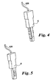
- Plug-in forms as shown in FIGS. 4 and 5 are particularly suitable for contacting the hole receptacle or the peripheral recess. In this case, the plug can be fixed in the hole receptacle with advantage via a non-positive or force-locking connection.
- the plug of its particular oblong and parallelepiped-shaped Kunststoff Kunststoffssens redesign laterally projecting spring-trained extensions have (Fig. 5).
- the plug-in contact circular, so that it is screwed with its likewise circular in cross-section Kunststofftechnischmaschines redesign in a correspondingly formed hole receptacle.
- the hole holder may be equipped with a finished thread or this can only be cut by screwing the plug contact.
- Figure 3 shows the hole recording in an enlarged detail.
- the hole receptacle is preferably formed in the form of a punched passage, so in that upwardly or downwardly directed contact tongue sections (8) are formed around the hole receptacle and, as a result, an enlargement of the contact surface is produced and thus an optimization of the contacting is ensured.
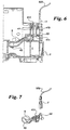
- FIG. 6 shows one half of a multi-pole circuit breaker.
- a connection contact 5 is mounted for each switching pole, which is shown separately in Fig. 7.
- Each terminal 5 carries the interior of the switching device a fixed contact 43, which cooperates with an associated contact bridge, not shown.
- the terminal contact 5 is provided with a first connection means 41 in the form of a terminal connection.
- the first connection means 41 has a clamping screw 412 guided in a threaded bore 411 of the connection contact 5 and a clamping disk 413 mounted thereon. At least one first external electrical conductor can be connected via the first connection means 41. Beyond the threaded bore 411, i.
- connection contact 5 runs in a bent at right angles to the front second connection means 52 in the form of a flat plug contact.
- a socket 7 in the form of a flat socket force and form-fitting attachable.
- the female connector 7 is fixedly connected to one end of a second external conductor 520.
- the second connection means 52 is formed centrally to the terminal contact, that is, it is in alignment with the axis longitudinal axis of the clamping screw 412.
- the second connection means 52 is only so wide formed that on both sides of the same comfortable first external conductor in the terminal space of the first connection means 41 can be introduced. This can be in the terminal space with advantage fork-like connection elements introduce, as used in particular in three-phase track blocks.
Landscapes
- Switch Cases, Indication, And Locking (AREA)
- Connections Arranged To Contact A Plurality Of Conductors (AREA)
- Breakers (AREA)
- Saccharide Compounds (AREA)
- Glass Compositions (AREA)
- Details Of Connecting Devices For Male And Female Coupling (AREA)
- Control Of Throttle Valves Provided In The Intake System Or In The Exhaust System (AREA)
- Lock And Its Accessories (AREA)
- Valve Device For Special Equipments (AREA)
Description
- Die Erfindung betrifft ein elektrisches Schaltgerät nach dem Oberbegriff des Anspruches 1. Insbesondere betrifft die Erfindung Schaltgeräte, wie Schütze Motorschutzschalter, Leitungsschutzschalter oder Leistungsschalter oder dergleichen. Aber auch programmierbare Schaltgeräte, wie speicherprogrammierbare Steuerungen oder programmierbare Relais sind im Anwendungsbereich der Erfindung angedacht.
- Herkömmliche Schaltgeräte wie zum Beispiel Schütze weisen eingangs- und ausgangsseitig für jeden zu schaltenden Pol einen Anschlusskontakt in Form eines Festkontaktes auf. Zum Zwecke der Verbindung, beziehungsweise Unterbrechung werden die zugehörigen Festkontakte über eine durch einen Magnetantrieb angetriebene Kontaktbrücke verbunden bzw. getrennt. Bei derartigen Geräten sind die von außen zugänglichen Festkontaktanschlüsse in der Regel über seitlich zugängliche Schraubanschlüsse, die von der Geräteoberseite verschraubt bzw. gelöst werden können oder durch seitlich oder von oben zugängliche und auch wieder von der Seite oder von oben lösbare Federklemmanschlüsse, gebildet.
- Aus der Druckschrift DE 201 20 504 U1 ist bereits ein Schaltgerät mit derartigen Anschlussvorrichtungen bekannt. Dieses Schaltgerät ist auf der einen Polseite mit Schraubanschlüssen bestückt und auf der anderen gegenüberliegenden Polseite mit andersartigen Anschlusselementen, wie zum Beispiel mit Federklemmelementen ausgestattet.
- Ferner ist aus der Druckschrift DE 100 23 851 A1 eine Anschlussklemme für Schaltgeräte bekannt, bei der ein basismäßig vorgesehener Schraubanschluss durch ein Modul für einen Federklemmanschluss ausgetauscht werden kann.
- Der Druckschrift EP 0 633 588 A1 ist eine Anschlussvorrichtung mit einer Stromschiene zu entnehmen, über die eine Haupt-Schraubklemme und eine Hilfs-Schraubklemme verbunden sind. Die Druckschrift FR 2 742 918 A1 zeigt ein Schaltgerät, das anschlussseitig mit aufwändig herzustellenden, metallischen Klemmenblöcken versehen ist, in denen jeweils eine Schraubklemme gelagert und eine Anschlussfahne zur Verbindung mit einer Flachsteckhülse ausgebildet ist. In ähnlicher Weise offenbart die US 5 107 396 ein Schaltgerät mit metallischen Klemmenblöcken, die Klemmschrauben für Lastanschlusskabelschuhe und unmittelbar darunter befestigte, mit umgebenden Isolierhülsen nach außen vorstehende Kontaktwinkel für Hilfsdrahtleiter aufweisen.
- Aus der Druckschrift FR 1 289 699 A ist eine Schaltgerät mit Schraubklemmen zu entnehmen, die es mittels speziell ausgebildeter Klemmschrauben gestatten, parallel zwei elektrische Rundleiter anzuschließen.
- Die vorbeschriebenen Ausführungsformen haben sich in der Praxis bereits weitestgehend bewährt. Aufgabe der Erfindung ist es ein Schaltgerät zu schaffen, welches im Hinblick auf die Anschlusstechnik optimiert ist. Es soll sowohl eine einfache Benutzung durch den Anwender gewährleistet, als auch die Flexibilität im Hinblick auf die Vielfältigkeit der Anschlussmöglichkeiten verbessert werden.
- Ausgehend von einem zumindest einpolig ausgebildeten Schaltgerät, bei dem jeder Pol zumindest einen ankommenden und einen abgehenden Anschlusskontakt, jeder der Anschlusskontakte erste Anschlussmittel für den Anschluss eines ersten externen elektrischen Leiters und zumindest einer der Anschlusskontakte zweite Anschlussmittel für den Anschluss eines zweiten elektrischen Leiters aufweist, wird die Aufgabe dadurch gelöst, dass die ersten und die zweiten Anschlussmittel sowie eine Verbindungsstelle zur geräteintemen Kontaktierung Bestandteile eines zungenartigen Kontaktträgers sind. Zur Geräteaußenseite realisiert das erfindungsgemäße Schaltgerät in konstruktiv und technologisch unaufwändiger Weise sowohl in herkömmlicher Art und Weise ausgebildete erste Anschlussmittel als auch zweite Anschlussmittel für zusätzliche Anschlussglieder.
- Die zweiten Anschlussmittel sind gegenüber den ersten Anschlussmitteln entweder näher zum Inneren oder näher zum Äußeren des Schaltgerätes angeordnet.
- Der Anschlusskontakt trägt erfindungsgemäß einen zum Geräteinneren führenden Festkontakt (z.B. bei Schützen) oder eine Verbindungsstelle für den Anschluss an elektrische interne Geräteleiter (z.B. bei programmierbaren Steuergeräten). Die ersten Anschlussmittel sind in Form herkömmlicher Schraubldemmanschlüsse. Federklemmanschlüsse (z.B. Käfig-Zugfederklemmanschlüsse), Schneidklemmanschlüsse oder anderer Anschlussmittel ausgebildet.
- Die zusätzlichen zweiten Anschlussmittel sind als Mittel für die kraft- und/oder formschlüssige Aufnahme eines Anschlussgliedes insbesondere in Form eines Steckanschlusses oder eines Schraubanschlusses ausgebildet.
- In einer bevorzugten Ausführungsform sind die zweiten Anschlussmittel als zentrale Lochaufnahmen für als Steckkontakte ausgebildete Anschlussglieder ausgeführt. Zur Optimierung der Kontaktierung bei dem zweiten Anschlussmittel ist die lochartige Ausnehmung - sei sie geschlossen (Lochaufnahme) oder randseitig offen (seitliche Ausnehmung) - als gestanzter Durchzug ausgebildet, so dass randseitig um die Ausnehmung herum zumindest bereichsweise zungenartige Erweiterungen nach außen abstehend gebildet sind. Hierdurch wird auf konstruktionsmäßig einfachste Art eine zusätzliche Anschlussmöglichkeit für den von außen zugänglichen Anschlusskontakt realisiert. Andere Ausführungen, wie eine seitliche Ausnehmung des Anschlussgliedes bzw. des Kontaktträgers sind ebenso möglich.
- In einer anderen bevorzugten Ausführungsform sind die zweiten Anschlussmittel als Steckkontakte ausgebildet. Bei zentraler Ausbildung der Steckkontakte können die ersten externen elektrischen Leiter bequem an den Steckkontakten links oder rechts oder beidseitig vorbei in die ersten Anschlussmittel eingeführt werden.
- Für den Zugang zu den zweiten im Geräteinneren angeordneten Anschlussmitteln weist das aus Isolierstoffmaterial bestehende Gehäuse wahlweise in einem Bereich oberhalb der zweiten Anschlussmittel Sollbruchstellen auf, die einen durch Herausbrechen herstellbaren Zugangsbereich definieren. Auch kann der Zugangsbereich ursprünglich frei (unverschlossen) ausgebildet sein.
- Weitere Einzelheiten und Vorteile der Erfindung ergeben sich aus dem folgenden, anhand von Figuren erläuterten Ausführungsbeispiel. Dabei wird die Erfindung stellvertretend für alle anderen elektrischen Schaltgeräte am Beispiel eines Schützes erläutert. Es zeigen
- Figur 1:
- ein mehrpoliges Schütz in schematischer Explosionsdarstellung;
- Figur 2a:
- Anschlusskontakte des Schützes mit verschiedenen ersten Anschlussmitteln (Schraubklemm- bzw. Federklemmanschlüssen) sowie einer möglichen Ausführung der zweiten Anschlussmittel (Lochaufnahme) gemäß Fig. 1;
- Figur 2b:
- eine alternative Ausführungsform der zweiten Anschlussmittel;
- Figur 3:
- eine Detaildarstellung der Lochaufnahme gemäß Fig. 2;
- Figur 4, 5:
- mögliche Ausführungen eines Steckkontaktes für die Lochaufnahme gemäß Fig.2a;
- Figur 6:
- einen mehrpoligen Schutzschalter im Teillängsschnitt mit einer weitere Ausführungsform der zweiten Anschlussmittel;
- Figur 7:
- eine perspektivische Einzeldarstellung aus Fig. 6.
- Fig. 1 zeigt in schematischer Explosionsdarstellung den Aufbau eines mehrpoligen Schützes (vorliegend z.B. 3-polig oder 4-polig nebst Versorgungsanschluss für die Antriebsspule des Magnetantriebs) mit einem Gehäuse 2 aus Isolierstoff, wobei jeder Pol einen ankommenden und einen abgehenden Anschlusskontakt 4 aufweist.
- Das Gehäuse 2 des Schützes ist vorliegend dreiteilig ausgeführt und besteht aus einem Basisgehäuseteil 2a zur Aufnahme eines Magnetantriebs, einem auf das Basisgehäuseteil 2a aufsetzbaren oberen Gehäuseteil 2b und einem Gehäusedeckel 2c. Ferner sind beidseitig die Anschlusskontakte 4 dargestellt, die für den Anschluss ankommender und abgehender Anschlussleitungen dienen. Das Gehäuse 2 kann je nach Schaltgerätetyp auch zweiteilig oder gar einteilig ausgebildet sein. Eingeklammert sind als Alternativanschlüsse zu den dargestellten Anschlussklemmen 4a mit Federklemmanschluss auch Anschlussklemmen 4b mit Schraubklemmanschluss dargestellt. Für das dargestellte Gehäuse 2 sind vorliegend Anschlussklemmen 4a mit Federklemmanschluss vorgesehen. Für etwaige Anschlussklemmen 4b mit Schraubklemmanschluss müsste das vorhandene Deckelteil 2c ausgetauscht werden, welches dann entsprechende Zugangsöffnungen für die Schraubenköpfe anstatt Öffnungen für die Federklemmen aufweist Das dargestellte Deckelteil 2c ist für die Anschlussklemmen 4a mit Federklemmanschluss vorgesehen und weist eine erste Reihe von Öffnungen 21 für die Verbindung bzw. den Zugang von ersten Anschlussleitungen 410 mit bzw. zu ersten Anschlussmitteln 41 des Anschlusskontaktes 4a, eine zweite Reihe von (Doppel-) Öffnungen 22 für den Eingriff eines Werkzeuges (z.B. Schraubendreher) und eine dritte Reihe von Öffnungen 23 bzw. eine Öffnung in Form eines Öffnungsschlitzes für die Verbindung von zweiten Anschlussleitungen 420 mit zusätzlichen zweiten Anschlussmitteln 42 des Anschlusskontaktes 4 auf. Die gemäß der Erfindung vorgesehene zusätzliche Reihe von Öffnungen 23 (bzw. der Öffnungsschlitz) ist in einer bevorzugten Ausführung der Erfindung im Ausgangszustand über ein Deckelteil verschlossen. Dabei kann die Öffnung durch ein wiederverschließbares Deckelteil über eine Rastverbindung oder ein Filmscharnier verschlossen sein. Vorzugsweise ist die Öffnung 23 jedoch nicht wieder verschließbar durch einen oder mehrere von Söllbruchstellen umrissene(n) heraustrennbare(n) Gehäusebereich(e), der (die) den späteren Zugangsbereich zu den zweiten Anschlussmitteln 42 bildet (bilden) verschlossen. Hierdurch wird eine besonders einfache Konstruktion gewährleistet und zusätzlicher Lager- und Verwaltungsaufwand für separate Deckelteile vermieden.
- Als ankommender bzw. abgehender Anschlusskontakt 4 sind zwei verschiedene alternative Ausführungen dargestellt. In einer ersten Ausführungsform ist der Anschlusskontakt 4a mit ersten Anschlussmitteln 41 in Form von Federklemmanschlüssen gebildet, während in der alternativen Ausführung anstelle der Federklemmanschlüsse Schraubklemmanschlüsse angeordnet sind. Beiden Ausführungen gemein ist die erfindungsgemäße Ausbildung mit zusätzlichen zweiten Anschlussmitteln 42. Bevorzugt ist ein erfindungsgemäßer Anschlusskontakt 4 durch eine zungenartige Anschlussfahne gebildet, die zum Geräteinneren an elektrische Geräteleiter angeschlossen ist oder wie im vorliegenden Fall einfach als Kontaktträger einen Festkontakt 43 trägt, die zur Geräteaußenseite hin in herkömmlicher Art und Weise die ersten Anschlussmittel 41 (wie Schraubklemmanschlüsse oder Federklemmanschlüsse) aufweist und die im Bereich zwischen diesen Anschlussstellen die - vorzugsweise als Lochaufnahme ausgebildeten - zweiten Anschlussmittel 42 aufweist. Dabei sind die zweiten Anschlussmittel 42 vorzugsweise von den ersten Anschlussmitteln 41 räumlich beabstandet und in ihrer Betätigung bzw. Anschlussbedienung autark ausgebildet derart, dass bei einer Verdrahtung der ersten Anschlussmittel 41 zum einen die zweiten Anschlussmittel für eine weitere Verdrahtung frei zugänglich sind und andererseits für eine Verdrahtung der zweiten Anschlussmittel 42 die ersten Anschlussmittel 41 nicht betätigt (gelöst und wieder gesichert) werden.
- Zur Kontaktierung der zweiten Anschlussmittel 42 dient insbesondere ein als Steckkontakt ausgebildetes Anschlussglied 6. Mittels dieses Anschlussgliedes 6 ist der entsprechende Schützkontakt in herkömmlicher Weise frei zu verdrahten. Insbesondere sind auch formstabile kombinierte Mehrfachsteckkontakte vorkonfektionierbar, so dass beispielsweise zwei benachbarte Schütze über die jeweils zweiten Anschlussmittel 42 in Form einer Wendeschaltung oder einer Stern-Dreieckschaltung auf einfache Weise über formfeste Steckkontaktreihen (vor-)verdrahtet werden können. Auch andere Anwendungen wie die Kombination eines Motorschutzschalters mit einem Schütz zu einem einfachen Motorstarter können bei entfernt positionierten zu verdrahtenden Geräten auf einfache Weise durch vorkonfektionierte Mehrfachsteckkontakte, die über flexible Freiverdrahtung verbunden sind, realisiert werden. All diese Anwendungen können durch die Erfindung auf besonders einfache Weise verdrahtet werden, ohne dass hierdurch etwa bereits die Standard-Anschlussstelle "verbraucht" bzw. belegt wäre. Für den Fall weiterer Verdrahtungen müsste demnach nicht eine bereits belegte Anschlussstelle gelöst, weitere Kabel eingelegt und die Anschlussstelle wieder gesichert werden. Hierdurch wird eine häufige Fehlerquelle ausgeschaltet - bereits funktionsfähige Verbindungen müssen nicht mehr gelöst werden oder zusätzliche Kabel untergeschoben werden. So wird vermieden, dass bei nachträglicher Verdrahtung ursprünglich funktionierende Verdrahtungen auf einmal fehlerhaft werden, weil vielleicht eine bereits verdrahtete Leitung sich gelöst hat. Weiterhin ist vorgesehen, die Schnittstelle auch für eine Funktionskontrolle zu nutzen. Eine Funktionskontrolle ist bei dem erfindungsgemäßen Gegenstand ohne ein Entfernen der Anschlussverdrahtung möglich.
- Figur 2a zeigt die beiden in Figur 1 bereits dargestellten alternativen Ausführungsform der Anschlusskontakte 4 des Schützes mit verschiedenen ersten Anschlussmitteln 41 (Schraubklemm- bzw. Federklemmanschlüssen) sowie einer möglichen Ausführung der zweiten Anschlussmittel 42 in Form einer Lochaufnahme. Anstelle der Lochaufnahme sind auch andere Kontaktierungs- bzw. Anschlussmöglichkeiten denkbar, wie z.B. eine oder mehrere lediglich randseitige nutartige Ausnehmungen des Anschlusskontaktes 4 bzw. des Kontaktträgers (Fig. 2b). Für eine Kontaktierung der Lochaufnahme oder der randseitigen Ausnehmung eignen sich insbesondere Steckerformen wie in den Figuren 4 und 5 abgebildet. Dabei ist der Stecker mit Vorteil über eine kraftschlüssige oder kraftformschlüssige Verbindung in der Lochaufnahme fixierbar. Hierfür kann der Stecker von seinem insbesondere länglich und quaderförmig ausgebildeten Kontaktierungskörper seitlich abstehende fedemd ausgebildete Fortsätze aufweisen (Fig. 5). Des Weiteren ist auch denkbar, den Steckkontakt im Querschnitt gesehen kreisrund auszubilden, so dass dieser mit seinem ebenfalls im Querschnitt kreisrunden Kontaktierungskörper in eine entsprechend ausgebildete Lochaufnahme einschraubbar ist. Hierfür kann die Lochaufnahme mit einem fertigen Gewinde ausgestattet sein oder aber dieses erst durch Eindrehen des Steckkontaktes eingeschnitten werden.
- Figur 3 zeigt die Lochaufnahme in einer vergrößerten Detaildarstellung. Dabei ist die Lochaufnahme vorzugsweise in Form eines gestanzten Durchzugs ausgebildet, so dass um die Lochaufnahme herum nach oben oder nach unten gerichtete Kontaktzungenabschnitte (8) gebildet sind und hierdurch eine Vergrößerung der Kontaktfläche entsteht und somit eine Optimierung der Kontaktierung gewährleistet wird.
- Figur 6 zeigt eine Hälfte eines mehrpoligen Schutzschalters. In einem Gehäuse 2 ist für jeden Schaltpol ein Anschlusskontakt 5 gelagert, der in Fig. 7 gesondert dargestellt ist. Jeder Anschlusskontakt 5 trägt zum Inneren des Schaltgerätes einen Festkontakt 43, der mit einer zugehörigen, nicht dargestellten Kontaktbrücke zusammenwirkt. Nach außen hin ist der Anschlusskontakt 5 mit einem ersten Anschlussmittel 41 in Form eines Klemmanschlusses versehen. Das erste Anschlussmittel 41 weist eine in einer Gewindebohrung 411 des Anschlusskontaktes 5 geführten Klemmschraube 412 und eine auf dieser gelagerten Klemmscheibe 413 auf. Über das erste Anschlussmittel 41 kann mindestens ein erster extern elektrischer Leiter angeschlossen werden. Jenseits der Gewindebohrung 411, d.h. näher zum Äußeren des Schutzschalters gelegen, läuft der Anschlusskontakt 5 in einem im rechten Winkel zur Frontseite abgebogenen zweiten Anschlussmittel 52 in Form eines flachen Steckkontaktes aus. Auf dieses zweite Anschlussmittel 52 ist eine Steckbuchse 7 in Form einer flachen Steckhülse kraft- und formschlüssig aufsteckbar. Die Steckbuchse 7 ist fest mit einen Ende eines zweiten externen Leiters 520 verbunden. Das zweite Anschlussmittel 52 ist mittig zum Anschlusskontakt ausgebildet, d.h., es befindet sich in Flucht zur Achse Längsachse der Klemmschraube 412. Das zweite Anschlussmittel 52 ist dabei nur so breit ausgebildet, dass zu beiden Seiten desselben bequem erste externe Leiter in das Klemmraum des ersten Anschlussmittels 41 eingeführt werden können. Damit lassen sich in den Klemmenraum auch mit Vorteil gabelartig ausgebildete Anschlusselemente einführen, wie sie insbesondere bei Drehstromschienenblöcken verwendet werden.
Claims (11)
- Elektrisches mindestens einpolig ausgebildetes Schaltgerät mit einem Gehäuse (2) aus Isolierstoffmaterial.- wobei jeder Pol zumindest einen ankommenden und einen abgehenden Anschlusskontakt (4; 5) aufweist und jeder der Anschlusskontakte (4; 5) erste Anschlussmittel (41) für den Anschluss mindestens eines ersten externen elektrischen Leiters aufweist und- zumindest einer der Anschlusskontakte (4; 5) zweite Anschlussmittel (42; 52) zur steckbaren Verbindung mit einem zweiten elektrischen Leiter aufweist,dadurch gekennzeichnet, dass- jeder Anschlusskontakt (4) einen zungenförmigen Kontaktträger mit einer an einem Ende angeordneten Verbindungsstelle zur geräteinternen Kontaktierung, den ersten Anschlussmitteln (41) sowie den zweiten Anschlussmitteln (42; 52) aufweist.
- Schaltgerät nach Anspruch 1, dadurch gekennzeichnet, dass die zweiten Anschlussmittel (42; 52) zwischen den jeweiligen Verbindungsstellen und anderendig angeordneten ersten Anschlussmitteln (41) angeordnet sind.
- Schaltgerät nach Anspruch 1, dadurch gekennzeichnet, dass die ersten Anschlussmittel (41) zwischen den jeweiligen Verbindungsstellen und anderendig angeordneten zweiten Anschlussmitteln (42; 52) angeordnet sind.
- Schaltgerät nach Anspruch 2 oder 3, dadurch gekennzeiehnet, dass die Verbindungsstelle als Festkontakt (43) eines Schaltkontaktes oder in Form einer Verbindungsstelle zur Verdrahtung ausgebildet ist.
- Schaltgerät nach einem der Ansprüche 1 bis 3, dadurch gekennzeichnet, dass die ersten Anschlussmittel (41) als Schraubklemmanschluss oder als Federklemmanschluss oder in Schneidklemmtechnik ausgebildet sind.
- Schaltgerät nach einem der Ansprüche 1 bis 3, dadurch gekennzeichnet, dass die zweiten Anschlussmittel (42; 52) für die kraft- und/oder formschlüssige Aufnahme eines Anschlussgliedes ausgebildet sind.
- Schaltgerät nach einem der Ansprüche 1 bis 3, dadurch gekennzeichnet, dass die zweiten Anschlussmittel (42) als Lochaufnahmen oder seitliche Ausnehmungen der Anschlusskontaktes (4) für die Aufnahme von mit den zweiten elektrischen Leitern verbundenen Steckkontakten (6) ausgebildet sind.
- Schaltgerät nach vorstehendem Anspruch, dadurch gekennzeichnet, dass die/jede Lochaufnahme einen zumindest bereichsweise randseitig nach oben und/oder unten gerichteten Kontaktzungenabschnitt (8) aufweist.
- Schaltgerät nach einem der Ansprüche 1 bis 3, dadurch gekennzeichnet, dass die zweiten Anschlussmittel (52) als zur Frontseite gerichtete Steckkontakte für die Aufnahme in mit den zweiten elektrischen Leitern verbundenen Kontaktbuchsen (7) ausgebildet sind.
- Schaltgerät nach vorstehendem Anspruch, dadurch gekennzeichnet, dass die zweiten Anschlussmittel (52) mittig zu den ersten Anschlussmitteln (41) angeordnet sind, wobei die ersten elektrischen Leiter beidseitig der Steckkontakte in die ersten Anschtussmittel (41) einführbar sind.
- Schaltgerät nach einem der vorstehenden Ansprüche, dadurch gekennzeichnet, dass das Gehäuse (2) für den Zugang zu den zweiten Anschlussmitteln (42; 52) einen von Sollbruchstellen umrissenen Zugangsbereich aufweist.
Applications Claiming Priority (3)
| Application Number | Priority Date | Filing Date | Title |
|---|---|---|---|
| DE10236790 | 2002-08-10 | ||
| DE10236790A DE10236790C1 (de) | 2002-08-10 | 2002-08-10 | Elektrisches Schaltgerät |
| PCT/EP2003/008757 WO2004023506A1 (de) | 2002-08-10 | 2003-08-07 | Elektrisches schaltgerät |
Publications (3)
| Publication Number | Publication Date |
|---|---|
| EP1529302A1 EP1529302A1 (de) | 2005-05-11 |
| EP1529302B1 true EP1529302B1 (de) | 2006-04-12 |
| EP1529302B2 EP1529302B2 (de) | 2017-05-24 |
Family
ID=28051356
Family Applications (1)
| Application Number | Title | Priority Date | Filing Date |
|---|---|---|---|
| EP03793698.6A Expired - Lifetime EP1529302B2 (de) | 2002-08-10 | 2003-08-07 | Elektrisches schaltgerät |
Country Status (7)
| Country | Link |
|---|---|
| US (1) | US7609137B2 (de) |
| EP (1) | EP1529302B2 (de) |
| CN (1) | CN100359620C (de) |
| AT (1) | ATE323323T1 (de) |
| DE (2) | DE10236790C1 (de) |
| ES (1) | ES2262011T3 (de) |
| WO (1) | WO2004023506A1 (de) |
Families Citing this family (22)
| Publication number | Priority date | Publication date | Assignee | Title |
|---|---|---|---|---|
| DE10338122B3 (de) * | 2003-08-15 | 2005-04-21 | Moeller Gmbh | Schaltgeräte-Leiterplatten-Kombination |
| DE102004043468A1 (de) * | 2004-09-08 | 2006-03-30 | Siemens Ag | Schaltgerät mit steckbaren Anschlüssen |
| EP1837887A1 (de) | 2006-03-20 | 2007-09-26 | Siemens Aktiengesellschaft | Eine Verbindungsvorrichtung und diese enthaltendes Niederspannungs-Schaltgerät |
| US7540792B2 (en) * | 2006-08-07 | 2009-06-02 | General Electric Company | Switching apparatus |
| KR100789448B1 (ko) * | 2006-12-29 | 2007-12-28 | 엘에스산전 주식회사 | 배선용 차단기용 단자 모듈 조립체 및 상기 단자 모듈조립체를 장착한 배선용 차단기 |
| DE102008017245B4 (de) | 2008-04-04 | 2010-03-25 | Moeller Gmbh | Steckadapter für ein elektrisches Schaltgerät |
| WO2011015232A1 (en) * | 2009-08-04 | 2011-02-10 | Abb Ab | A switching device |
| EP2462607B1 (de) * | 2009-08-04 | 2012-10-31 | Abb Ab | Schaltvorrichtung |
| DE102010032522A1 (de) | 2010-07-28 | 2012-02-02 | Siemens Aktiengesellschaft | Klemmanordnung für einen Leistungsschalter in Federzugtechnik |
| US8579641B1 (en) | 2011-03-14 | 2013-11-12 | Google Inc. | Multi-orientation plug |
| US8398430B1 (en) | 2011-03-14 | 2013-03-19 | Google Inc. | Multi-orientation plug |
| CN103311008B (zh) * | 2013-06-18 | 2015-04-01 | 江苏东源电器集团股份有限公司 | 采用可编程序的三工位开关 |
| US9184013B2 (en) | 2013-06-21 | 2015-11-10 | General Electric Company | Conductor guide member for a circuit breaker terminal assembly |
| FR3029699B1 (fr) * | 2014-12-08 | 2019-05-31 | Schneider Electric Industries Sas | Dispositif de raccordement electrique comportant une sortie auxiliaire et appareil de commutation comportant un tel dispositif. |
| DE102015202130A1 (de) | 2015-02-06 | 2016-08-11 | Schaeffler Technologies AG & Co. KG | Baukasten für Lager und Lageranordnung |
| DE102015104268A1 (de) | 2015-03-23 | 2016-09-29 | Eaton Electrical Ip Gmbh & Co. Kg | Elektrisches Schaltgerät mit elektrischen Klemmanschlüssen |
| DE102015213240B4 (de) * | 2015-07-15 | 2020-02-06 | Siemens Aktiengesellschaft | Schutzschalter |
| DE102015116085A1 (de) * | 2015-09-23 | 2017-03-23 | Abb Schweiz Ag | Elektrisches Schaltgerät |
| EP3356692A2 (de) | 2015-09-30 | 2018-08-08 | Schaeffler Technologies AG & Co. KG | Sensorsatz für lager und lageranordnung |
| DE102016221610A1 (de) | 2016-11-04 | 2018-05-09 | Schaeffler Technologies AG & Co. KG | Abstandsmessmodul zur Messung eines Abstandes in einem Lager sowie Sensorsatz und Lageranordnung |
| DE102016222179A1 (de) | 2016-11-11 | 2018-05-17 | Schaeffler Technologies AG & Co. KG | Sensormodul für ein mechanisches Lager mit einer Anschlussfahne sowie mechanisches Lager |
| FI11881U1 (fi) * | 2017-09-15 | 2017-12-05 | Abb Oy | Kytkinlaite, jonka kiinteä kosketin on varustettu mittausliittimellä |
Family Cites Families (16)
| Publication number | Priority date | Publication date | Assignee | Title |
|---|---|---|---|---|
| US2974302A (en) † | 1958-06-11 | 1961-03-07 | Int Register Co | Electrical terminal construction |
| DE1110275B (de) † | 1958-10-06 | 1961-07-06 | Busch Jaeger Duerener Metall | Elektrischer Nockenschalter |
| FR1286699A (fr) | 1960-01-06 | 1962-03-09 | Westinghouse Electric Corp | Disjoncteur pour circuits d'éclairage et circuits d'alimentation de puissance modérée |
| JPS5217728Y2 (de) † | 1971-03-16 | 1977-04-21 | ||
| US4393289A (en) † | 1976-12-30 | 1983-07-12 | Texas Instruments Incorporated | Circuit breaker |
| US4739293A (en) * | 1987-02-19 | 1988-04-19 | Westinghouse Electric Corp. | Electromagnetic contactor with reduced noise magnetic armature |
| US4951018A (en) * | 1989-01-26 | 1990-08-21 | Square D Company | Electromagnetic contactor |
| US4934948A (en) † | 1989-04-06 | 1990-06-19 | Carlingswitch, Inc. | Load terminal configuration for circuit breaker or the like |
| US5107396A (en) * | 1991-06-03 | 1992-04-21 | General Electric Company | Circuit breaker combined terminal lug and connector |
| US5281937A (en) * | 1992-07-14 | 1994-01-25 | Fasco Industries, Inc. | Electromagnetic contactor and method for making same |
| FR2707429B1 (fr) | 1993-07-07 | 1995-09-01 | Merlin Gerin | Accessoire de raccordement. |
| IT1275642B1 (it) † | 1994-10-18 | 1997-10-17 | Bticino Spa | Interruttore automatico miniaturizzato con morsetto polifunzionale e schermo di protezione contro gli archi elettrici interni |
| FR2742918B1 (fr) † | 1995-12-20 | 1998-02-06 | Schneider Electric Sa | Dispositif de raccordement d'un conducteur exterieur tel un cable a une plage de contact d'un appareil electrique |
| DE10023851A1 (de) * | 2000-05-16 | 2001-11-22 | Moeller Gmbh | Anschlußklemme |
| US6781491B2 (en) * | 2001-10-19 | 2004-08-24 | Eaton Corporation | Quick connect terminal for electric power switch |
| DE20120504U1 (de) * | 2001-12-19 | 2002-04-18 | Moeller GmbH, 53115 Bonn | Elektrisches Schaltgerät |
-
2002
- 2002-08-10 DE DE10236790A patent/DE10236790C1/de not_active Expired - Lifetime
-
2003
- 2003-08-07 CN CNB038240823A patent/CN100359620C/zh not_active Expired - Lifetime
- 2003-08-07 AT AT03793698T patent/ATE323323T1/de not_active IP Right Cessation
- 2003-08-07 DE DE50302965T patent/DE50302965D1/de not_active Expired - Lifetime
- 2003-08-07 WO PCT/EP2003/008757 patent/WO2004023506A1/de not_active Ceased
- 2003-08-07 EP EP03793698.6A patent/EP1529302B2/de not_active Expired - Lifetime
- 2003-08-07 US US10/524,068 patent/US7609137B2/en not_active Expired - Lifetime
- 2003-08-07 ES ES03793698T patent/ES2262011T3/es not_active Expired - Lifetime
Also Published As
| Publication number | Publication date |
|---|---|
| ATE323323T1 (de) | 2006-04-15 |
| WO2004023506A1 (de) | 2004-03-18 |
| EP1529302A1 (de) | 2005-05-11 |
| DE50302965D1 (de) | 2006-05-24 |
| CN1689128A (zh) | 2005-10-26 |
| HK1083039A1 (zh) | 2006-06-23 |
| CN100359620C (zh) | 2008-01-02 |
| DE10236790C1 (de) | 2003-10-16 |
| EP1529302B2 (de) | 2017-05-24 |
| US7609137B2 (en) | 2009-10-27 |
| ES2262011T3 (es) | 2006-11-16 |
| US20050270130A1 (en) | 2005-12-08 |
Similar Documents
| Publication | Publication Date | Title |
|---|---|---|
| EP1529302B1 (de) | Elektrisches schaltgerät | |
| EP2107587B1 (de) | Steckadapter für ein elektrisches Schaltgerät | |
| EP2255369B1 (de) | Reihenklemme, insbesondere trennklemme | |
| EP3221878B1 (de) | Schaltgerät sowie schaltgeräteanordnung | |
| EP1917672B1 (de) | Verbindungssystem mit einem elektromagnetischen schaltgerät, insbesondere schütz, und einem stecker | |
| DE102007027522B3 (de) | Schaltgerät | |
| EP1618578B1 (de) | Schaltschütz mit anschlussmodul zum ansteuern des magnetantriebes | |
| EP1447829A1 (de) | Installationsgerät und Installationsbaugruppe mit Installationsgerät | |
| EP1113525B1 (de) | Reihenklemme, insbesondere Wandlerklemme, mit einer Querbrückungsvorrichtung | |
| DE10134417C1 (de) | Elektrische Anschluß- oder Verbindungseinrichtung | |
| EP1312138B1 (de) | Elektrisches gerät mit verbinder für einen durchschleif-leiter | |
| EP0984513B1 (de) | Kontakteinsatz für Industriestecker | |
| EP0621670B1 (de) | Schalter mit Hilfsstromkreisen | |
| EP1787359B1 (de) | Strom-einspeisemodul | |
| DE19530947C2 (de) | Klemmblock für Elektrizitätszähler | |
| EP0921611B1 (de) | Netzstromanschlussdose und -schalter | |
| DE202007013483U1 (de) | Verbindungsklemmenblock für elektrische Mehrphasenmotoren | |
| EP2837063A1 (de) | Schaltverteiler | |
| DE102005026714B3 (de) | Schutzeinrichtung mit einer Schutzschaltereinheit und mit einer Überspannungsschutzeinheit | |
| EP1787358B1 (de) | Strom-einspeisemodul mit käfig-zugfederklemmen | |
| DE102022212200B4 (de) | Verdrahtungsmodul zur internen Kontaktierung eines Hilfsschalters, Verdrahtungssystem und Verfahren zum elektrischen Kontaktieren eines solchen Verdrahtungsmoduls | |
| DE20311424U1 (de) | Anschlusseinrichtung zum nachträglichen Anschließen eines elektrischen Verbrauchers an das Stromnetz eines Kraftfahrzeuges | |
| DE20120504U1 (de) | Elektrisches Schaltgerät | |
| DE102005010662A1 (de) | Elektromechanische Vorrichtung und Anschlusselement |
Legal Events
| Date | Code | Title | Description |
|---|---|---|---|
| PUAI | Public reference made under article 153(3) epc to a published international application that has entered the european phase |
Free format text: ORIGINAL CODE: 0009012 |
|
| 17P | Request for examination filed |
Effective date: 20050308 |
|
| AK | Designated contracting states |
Kind code of ref document: A1 Designated state(s): AT BE BG CH CY CZ DE DK EE ES FI FR GB GR HU IE IT LI LU MC NL PT RO SE SI SK TR |
|
| GRAP | Despatch of communication of intention to grant a patent |
Free format text: ORIGINAL CODE: EPIDOSNIGR1 |
|
| GRAS | Grant fee paid |
Free format text: ORIGINAL CODE: EPIDOSNIGR3 |
|
| GRAA | (expected) grant |
Free format text: ORIGINAL CODE: 0009210 |
|
| AK | Designated contracting states |
Kind code of ref document: B1 Designated state(s): AT BE BG CH CY CZ DE DK EE ES FI FR GB GR HU IE IT LI LU MC NL PT RO SE SI SK TR |
|
| PG25 | Lapsed in a contracting state [announced via postgrant information from national office to epo] |
Ref country code: CZ Free format text: LAPSE BECAUSE OF FAILURE TO SUBMIT A TRANSLATION OF THE DESCRIPTION OR TO PAY THE FEE WITHIN THE PRESCRIBED TIME-LIMIT Effective date: 20060412 Ref country code: FI Free format text: LAPSE BECAUSE OF FAILURE TO SUBMIT A TRANSLATION OF THE DESCRIPTION OR TO PAY THE FEE WITHIN THE PRESCRIBED TIME-LIMIT Effective date: 20060412 Ref country code: SI Free format text: LAPSE BECAUSE OF FAILURE TO SUBMIT A TRANSLATION OF THE DESCRIPTION OR TO PAY THE FEE WITHIN THE PRESCRIBED TIME-LIMIT Effective date: 20060412 Ref country code: SK Free format text: LAPSE BECAUSE OF FAILURE TO SUBMIT A TRANSLATION OF THE DESCRIPTION OR TO PAY THE FEE WITHIN THE PRESCRIBED TIME-LIMIT Effective date: 20060412 Ref country code: IE Free format text: LAPSE BECAUSE OF FAILURE TO SUBMIT A TRANSLATION OF THE DESCRIPTION OR TO PAY THE FEE WITHIN THE PRESCRIBED TIME-LIMIT Effective date: 20060412 Ref country code: NL Free format text: LAPSE BECAUSE OF FAILURE TO SUBMIT A TRANSLATION OF THE DESCRIPTION OR TO PAY THE FEE WITHIN THE PRESCRIBED TIME-LIMIT Effective date: 20060412 |
|
| REG | Reference to a national code |
Ref country code: GB Ref legal event code: FG4D Free format text: NOT ENGLISH |
|
| REG | Reference to a national code |
Ref country code: CH Ref legal event code: EP |
|
| REF | Corresponds to: |
Ref document number: 50302965 Country of ref document: DE Date of ref document: 20060524 Kind code of ref document: P |
|
| REG | Reference to a national code |
Ref country code: IE Ref legal event code: FG4D Free format text: LANGUAGE OF EP DOCUMENT: GERMAN |
|
| REG | Reference to a national code |
Ref country code: CH Ref legal event code: NV Representative=s name: DTS ZUERICH SCHWEIZER- UND EUROPAEISCHE PATENTANWA |
|
| REG | Reference to a national code |
Ref country code: SE Ref legal event code: TRGR |
|
| PG25 | Lapsed in a contracting state [announced via postgrant information from national office to epo] |
Ref country code: DK Free format text: LAPSE BECAUSE OF FAILURE TO SUBMIT A TRANSLATION OF THE DESCRIPTION OR TO PAY THE FEE WITHIN THE PRESCRIBED TIME-LIMIT Effective date: 20060712 |
|
| REG | Reference to a national code |
Ref country code: RO Ref legal event code: EPE |
|
| GBT | Gb: translation of ep patent filed (gb section 77(6)(a)/1977) |
Effective date: 20060726 |
|
| PG25 | Lapsed in a contracting state [announced via postgrant information from national office to epo] |
Ref country code: MC Free format text: LAPSE BECAUSE OF NON-PAYMENT OF DUE FEES Effective date: 20060831 Ref country code: BE Free format text: LAPSE BECAUSE OF NON-PAYMENT OF DUE FEES Effective date: 20060831 |
|
| PG25 | Lapsed in a contracting state [announced via postgrant information from national office to epo] |
Ref country code: PT Free format text: LAPSE BECAUSE OF FAILURE TO SUBMIT A TRANSLATION OF THE DESCRIPTION OR TO PAY THE FEE WITHIN THE PRESCRIBED TIME-LIMIT Effective date: 20060912 |
|
| NLV1 | Nl: lapsed or annulled due to failure to fulfill the requirements of art. 29p and 29m of the patents act | ||
| REG | Reference to a national code |
Ref country code: IE Ref legal event code: FD4D |
|
| REG | Reference to a national code |
Ref country code: ES Ref legal event code: FG2A Ref document number: 2262011 Country of ref document: ES Kind code of ref document: T3 |
|
| ET | Fr: translation filed | ||
| PLAX | Notice of opposition and request to file observation + time limit sent |
Free format text: ORIGINAL CODE: EPIDOSNOBS2 |
|
| PLBI | Opposition filed |
Free format text: ORIGINAL CODE: 0009260 |
|
| 26 | Opposition filed |
Opponent name: SIEMENS AKTIENGESELLSCHAFT, BERLIN UND MUENCHEN Effective date: 20070112 |
|
| REG | Reference to a national code |
Ref country code: CH Ref legal event code: PCAR Representative=s name: DTS ZUERICH, CH |
|
| PLBB | Reply of patent proprietor to notice(s) of opposition received |
Free format text: ORIGINAL CODE: EPIDOSNOBS3 |
|
| PG25 | Lapsed in a contracting state [announced via postgrant information from national office to epo] |
Ref country code: AT Free format text: LAPSE BECAUSE OF NON-PAYMENT OF DUE FEES Effective date: 20060807 |
|
| BERE | Be: lapsed |
Owner name: MOELLER G.M.B.H. Effective date: 20060831 |
|
| REG | Reference to a national code |
Ref country code: CH Ref legal event code: PCAR Free format text: DTS ZUERICH;RESIRAIN 1;8125 ZOLLIKERBERG (CH) |
|
| PG25 | Lapsed in a contracting state [announced via postgrant information from national office to epo] |
Ref country code: GR Free format text: LAPSE BECAUSE OF FAILURE TO SUBMIT A TRANSLATION OF THE DESCRIPTION OR TO PAY THE FEE WITHIN THE PRESCRIBED TIME-LIMIT Effective date: 20060713 |
|
| PLAB | Opposition data, opponent's data or that of the opponent's representative modified |
Free format text: ORIGINAL CODE: 0009299OPPO |
|
| PG25 | Lapsed in a contracting state [announced via postgrant information from national office to epo] |
Ref country code: BG Free format text: LAPSE BECAUSE OF FAILURE TO SUBMIT A TRANSLATION OF THE DESCRIPTION OR TO PAY THE FEE WITHIN THE PRESCRIBED TIME-LIMIT Effective date: 20060712 Ref country code: EE Free format text: LAPSE BECAUSE OF FAILURE TO SUBMIT A TRANSLATION OF THE DESCRIPTION OR TO PAY THE FEE WITHIN THE PRESCRIBED TIME-LIMIT Effective date: 20060412 |
|
| PG25 | Lapsed in a contracting state [announced via postgrant information from national office to epo] |
Ref country code: HU Free format text: LAPSE BECAUSE OF FAILURE TO SUBMIT A TRANSLATION OF THE DESCRIPTION OR TO PAY THE FEE WITHIN THE PRESCRIBED TIME-LIMIT Effective date: 20061013 Ref country code: LU Free format text: LAPSE BECAUSE OF NON-PAYMENT OF DUE FEES Effective date: 20060807 |
|
| PG25 | Lapsed in a contracting state [announced via postgrant information from national office to epo] |
Ref country code: CY Free format text: LAPSE BECAUSE OF FAILURE TO SUBMIT A TRANSLATION OF THE DESCRIPTION OR TO PAY THE FEE WITHIN THE PRESCRIBED TIME-LIMIT Effective date: 20060412 |
|
| RAP2 | Party data changed (patent owner data changed or rights of a patent transferred) |
Owner name: EATON INDUSTIES GMBH |
|
| PLAY | Examination report in opposition despatched + time limit |
Free format text: ORIGINAL CODE: EPIDOSNORE2 |
|
| RAP2 | Party data changed (patent owner data changed or rights of a patent transferred) |
Owner name: EATON INDUSTRIES GMBH |
|
| PLBC | Reply to examination report in opposition received |
Free format text: ORIGINAL CODE: EPIDOSNORE3 |
|
| APAH | Appeal reference modified |
Free format text: ORIGINAL CODE: EPIDOSCREFNO |
|
| APBM | Appeal reference recorded |
Free format text: ORIGINAL CODE: EPIDOSNREFNO |
|
| APBP | Date of receipt of notice of appeal recorded |
Free format text: ORIGINAL CODE: EPIDOSNNOA2O |
|
| APBQ | Date of receipt of statement of grounds of appeal recorded |
Free format text: ORIGINAL CODE: EPIDOSNNOA3O |
|
| PLAB | Opposition data, opponent's data or that of the opponent's representative modified |
Free format text: ORIGINAL CODE: 0009299OPPO |
|
| R26 | Opposition filed (corrected) |
Opponent name: SIEMENS AKTIENGESELLSCHAFT Effective date: 20070112 |
|
| PGFP | Annual fee paid to national office [announced via postgrant information from national office to epo] |
Ref country code: CH Payment date: 20130806 Year of fee payment: 11 Ref country code: RO Payment date: 20130801 Year of fee payment: 11 Ref country code: SE Payment date: 20130807 Year of fee payment: 11 Ref country code: ES Payment date: 20130726 Year of fee payment: 11 |
|
| PGFP | Annual fee paid to national office [announced via postgrant information from national office to epo] |
Ref country code: TR Payment date: 20130731 Year of fee payment: 11 |
|
| REG | Reference to a national code |
Ref country code: SE Ref legal event code: EUG Ref country code: CH Ref legal event code: PL |
|
| PG25 | Lapsed in a contracting state [announced via postgrant information from national office to epo] |
Ref country code: CH Free format text: LAPSE BECAUSE OF NON-PAYMENT OF DUE FEES Effective date: 20140831 Ref country code: LI Free format text: LAPSE BECAUSE OF NON-PAYMENT OF DUE FEES Effective date: 20140831 Ref country code: RO Free format text: LAPSE BECAUSE OF NON-PAYMENT OF DUE FEES Effective date: 20140807 |
|
| PG25 | Lapsed in a contracting state [announced via postgrant information from national office to epo] |
Ref country code: SE Free format text: LAPSE BECAUSE OF NON-PAYMENT OF DUE FEES Effective date: 20140808 |
|
| REG | Reference to a national code |
Ref country code: ES Ref legal event code: FD2A Effective date: 20150925 |
|
| PG25 | Lapsed in a contracting state [announced via postgrant information from national office to epo] |
Ref country code: ES Free format text: LAPSE BECAUSE OF NON-PAYMENT OF DUE FEES Effective date: 20140808 |
|
| APBU | Appeal procedure closed |
Free format text: ORIGINAL CODE: EPIDOSNNOA9O |
|
| REG | Reference to a national code |
Ref country code: FR Ref legal event code: PLFP Year of fee payment: 14 |
|
| PUAH | Patent maintained in amended form |
Free format text: ORIGINAL CODE: 0009272 |
|
| STAA | Information on the status of an ep patent application or granted ep patent |
Free format text: STATUS: PATENT MAINTAINED AS AMENDED |
|
| RAP2 | Party data changed (patent owner data changed or rights of a patent transferred) |
Owner name: EATON ELECTRICAL IP GMBH & CO. KG |
|
| 27A | Patent maintained in amended form |
Effective date: 20170524 |
|
| AK | Designated contracting states |
Kind code of ref document: B2 Designated state(s): AT BE BG CH CY CZ DE DK EE ES FI FR GB GR HU IE IT LI LU MC NL PT RO SE SI SK TR |
|
| REG | Reference to a national code |
Ref country code: DE Ref legal event code: R102 Ref document number: 50302965 Country of ref document: DE |
|
| REG | Reference to a national code |
Ref country code: FR Ref legal event code: PLFP Year of fee payment: 15 |
|
| PG25 | Lapsed in a contracting state [announced via postgrant information from national office to epo] |
Ref country code: TR Free format text: LAPSE BECAUSE OF NON-PAYMENT OF DUE FEES Effective date: 20140807 |
|
| REG | Reference to a national code |
Ref country code: FR Ref legal event code: PLFP Year of fee payment: 16 |
|
| PGFP | Annual fee paid to national office [announced via postgrant information from national office to epo] |
Ref country code: IT Payment date: 20220720 Year of fee payment: 20 Ref country code: GB Payment date: 20220721 Year of fee payment: 20 Ref country code: DE Payment date: 20220616 Year of fee payment: 20 |
|
| PGFP | Annual fee paid to national office [announced via postgrant information from national office to epo] |
Ref country code: FR Payment date: 20220721 Year of fee payment: 20 |
|
| P01 | Opt-out of the competence of the unified patent court (upc) registered |
Effective date: 20230521 |
|
| REG | Reference to a national code |
Ref country code: DE Ref legal event code: R071 Ref document number: 50302965 Country of ref document: DE |
|
| REG | Reference to a national code |
Ref country code: GB Ref legal event code: PE20 Expiry date: 20230806 |
|
| PG25 | Lapsed in a contracting state [announced via postgrant information from national office to epo] |
Ref country code: GB Free format text: LAPSE BECAUSE OF EXPIRATION OF PROTECTION Effective date: 20230806 |