EP2251945B1 - Stromschienen- und Verbindersystem - Google Patents
Stromschienen- und Verbindersystem Download PDFInfo
- Publication number
- EP2251945B1 EP2251945B1 EP10004787.7A EP10004787A EP2251945B1 EP 2251945 B1 EP2251945 B1 EP 2251945B1 EP 10004787 A EP10004787 A EP 10004787A EP 2251945 B1 EP2251945 B1 EP 2251945B1
- Authority
- EP
- European Patent Office
- Prior art keywords
- plug
- module
- contacts
- switching devices
- arrangement according
- Prior art date
- Legal status (The legal status is an assumption and is not a legal conclusion. Google has not performed a legal analysis and makes no representation as to the accuracy of the status listed.)
- Not-in-force
Links
Images

Classifications
-
- H—ELECTRICITY
- H02—GENERATION; CONVERSION OR DISTRIBUTION OF ELECTRIC POWER
- H02B—BOARDS, SUBSTATIONS OR SWITCHING ARRANGEMENTS FOR THE SUPPLY OR DISTRIBUTION OF ELECTRIC POWER
- H02B1/00—Frameworks, boards, panels, desks, casings; Details of substations or switching arrangements
- H02B1/20—Bus-bar or other wiring layouts, e.g. in cubicles, in switchyards
- H02B1/205—Bus-bar or other wiring layouts, e.g. in cubicles, in switchyards for connecting electrical apparatus mounted side by side on a rail
Definitions
- the invention relates to a multi-pole arrangement of a busbar and connector system for power supply for at least two juxtaposed on a longitudinally extending support member electrical switching devices.
- An example system to be named in DE 4021825 C2 is the common power supply for arranged on a support member switchgear, the power supply via a busbar, from which to each switching device L-shaped connector elements produce the power supply.
- the connector elements For assembly and disassembly, the connector elements must each be attached or detached with a tool.
- the busbar system comprises parallel juxtaposed flat rails in a multi-walled box profile made of insulating material, and holding elements which can be applied to a support member and serve to hold the flat rails, wherein the holding elements are perpendicular to the support member and the busbar system, so that the flat rails parallel to itself come to lie longitudinally extending support member.
- the flat rails have a longitudinal extent, which corresponds to at least the sum of the width of several with their back on the support member anreihbarer switching devices, and are held such that only their narrow sides are freely accessible from the outside.
- the connector system of said system comprises externally mounted on the narrow sides of the flat rails electrical conductor connections, which serve the potential guidance of the flat rails to the switching devices.
- the conductor connections are designed as flexible lines, the end contacts via screw terminals during assembly and disassembly individually secured with a tool, or must be solved.
- the end contacts have no electrical insulation and that the screw terminals are not secured against loss of the screws.
- multi-pole arrangements of a busbar and connector system are known in which a single holding element for conductor elements (plug-in adapter) is present, which on the back of a support member (rail) is firmly connected to this support member ( EP 1049227 A2 ; DE 102005023452 A1 ).
- a retaining element on the back of a support member leads to increase the mounting depth, for example in a cabinet.
- the EP 1049227 A2 shows a multi-part arrangement for the holding element.
- a first element is (preferably) formed integrally with the support member; a second element serves to receive the flat rails. Both elements are formed locked with each other.
- the multi-part construction has disadvantages in terms of production and material costs.
- the invention has for its object to provide a busbar and connector system in which a simple and quick installation or disassembly should be possible and in which the contacts to the flat bars and the switching devices finger-safe against contact with the live elements are formed.
- the essence of the invention is that conductor connections are formed in plug-in modules that serve the potential guidance of the flat rails to the switching devices.
- Next female input contacts of the conductor connections for contacting in the flat rails and male access contacts of the conductor connections for contacting with the switching devices are designed as a rigid plug contacts.
- housing made of insulating material are each designed as plug-in modules.
- the respective switching devices associated plug-in modules may have different training, so that individual, different plug-in modules are formed.
- the advantage of the presented system is primarily in the possibility of quick and tool-free installation, or disassembly.
- the arrangement of conductor rail and connector system should be three-pole.
- a particular embodiment is that in a plug-in module only one conductor connection is introduced (single-pole plug-in module).
- the execution of a single-pole plug-in module can be made relatively narrow.
- three conductor connections between an electrical contact to the flat rail and a plug pin to the switching device are realized.
- the conductor connections can be made flexible (for example, as a stranded wire) or rigid.
- the conductor connections can run in the housing of the plug-in module or outside the housing.
- the rail and connector assembly serves to guide the potential of flat rails to connectable switching devices. It is assumed that switching devices, which can be arranged with their back on a support member, wherein the rule is considered that a trained as Hutprofilschiene support member is arranged horizontally in a distribution system or a control cabinet or the like.
- the front of the switchgear contains control elements and incoming and outgoing contacts.
- the arrangement according to the invention relates to switching devices whose access contacts (supply contacts, voltage supply) either all above (above horizontally arranged support member) or all below (below the horizontally arranged support member) are. According to the embodiments shown in the description and in the figures switching devices are treated in the present application, the access contacts are on top. However, the invention is not limited to this geometric situation, it can also be realized when the access contacts of the switching devices are down.
- the support elements for the busbar system are perpendicular to the support member and are on one side (above or below) away from the support member. They are designed with such a length that there is a free space between the busbar system and the stackable switching devices. It is thus referred to with clearance, the distance between the box section of the busbar system and the sides of the switching devices having the access contacts, is present without the considered side of the switching devices comes in proximity or contact with the box section.
- the holding elements are designed such that they can be pushed onto the support member or clipped.
- the plug-in modules according to the invention are provided with rigid contacts which are suitable for placement on the flat rails. These contacts may be formed, for example, as tulip contacts.
- a plug-in module may be formed in the width of an associated switching device.
- the box profile for receiving the flat rails has a closed rear side, which faces the support member. At this back the retaining elements are attached. The rear side opposite the open front provides access to the narrow sides of the flat rails.
- the individual flat rails are insulated from each other in the box section.
- the plug-in modules together have at least one plug in an access contact of a switching device conductor, so that potential is passed from a flat rail to the switching device.
- the plug-in conductor can be designed as a plug pin, for example crimped on a stranded wire.
- the design of the housing with a rigid guide the conductor connection is such that at least one existing at the end of the conductor connection plug-in element (hereinafter also Access contact) can be inserted directly into a feed or access opening of a stackable switching device.
- the input contacts and the access contacts are on one of the surfaces of a plug-in module projecting and formed parallel to each other.
- the length of a bus bar system may be shorter than the length of a holding member.
- a further (second) busbar system which is arranged immediately adjacent to the first busbar system on the holding member.
- a plug-in module referred to as a bridge module.
- the bridge module has at least one conductor connection which serves to bridge the potential of one of the flat rails of the first busbar system to one of the flat rails of the second busbar system.
- each conductor connection can be assigned a female plug contact in the housing.
- a so-called feed module (12X in Fig. 3 ) educated.
- the feed module is contacted with an example three-pole potential supply line, wherein the access line be made flexible.
- bridge module (12B in FIG Fig. 4E ) educated. Two juxtaposed bridge modules are electrically connected to each other via the plug contacts in the housing.
- a blanking cover is placed on the busbar system to cover the freely accessible opening so that live parts are finger-proof.
- a busbar system with two holding elements 30 is shown, which is applied to a trained as a hat rail support member 40.
- the busbar system consists - in a three-pole version - of three parallel side by side flat rails 21.
- the holding elements 30 are perpendicular to the support member 40 and the busbar system, so that the flat rails 21 come to lie parallel to the longitudinally extending support member 40.
- the holding elements 30 are located on one side of the supporting member 40 and are formed with a length H1 between the upper edge of the rail and bottom edge of the busbar system, so that a space H2 between the busbar system and the arrangable switching devices 50, 52 is present (see FIGS. 2 and 3 ).
- the holding elements 30 are designed so that they can be pushed onto the support member 40 or clipped.
- the flat rails 21 are arranged and held enclosed in a multi-walled box section 24 of insulating material. But their narrow sides 22 are freely accessible from the outside.
- the box section 24 has a closed rear side 25, which faces the support member 40 and on which the holding elements 30 are fixed and it has an open front side 26 opposite the rear side 25, which serves to access the narrow sides 22 of the flat rails 21.
- Fig. 2 shows a representation with mounted on the support member switching devices, but without plug-in modules.
- the busbar system has the length L. Between the upper edge of the switching devices and the lower edge of the busbar system is a free space H2 available. The switching devices do not come into contact or contact with the box profile 24. The switching devices have on the top access or feed-in contacts 54. Marked by reference B is a width dimension of a switching device 50, 52. As an advantage of the invention can be noted that switching devices with different Width dimensions and with different distances can be installed next to each other.
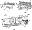
- the Fig. 3 shows a representation with various switching devices 50, 52 and various plug-in modules on the busbar system.
- the switching devices may have different widths or different height distances (clearance between the upper edge of the switching devices and lower edge of the busbar system).
- two busbar systems reference numerals 24 'and 24 " are arranged side by side.
- Plug-in modules according to the invention (12B, 12C, 12X) have at least one conductor connection 19A for conducting potential from the flat rails 21 to a switching device 50, 52, such that the conductor connection 19A between an electrical contact 16 for placing and contacting the flat rails 21 and a rigid pluggable Conductor element 15 ', 15 "extends, which is associated with a feed contact 54 on the switching device 50, 52.
- each conductor connection 19A, 19B may be assigned a female plug contact in the housing, cf. Plug-in modules 12B, 12X in Fig. 3 and in Fig. 4E ,
- a so-called potential feed module or feed module is thereby formed. It is used in addition to the contact between the flat rail and switching device of the e.g. Three-pole potential supply from the grid to the busbar system. It comprises a female contact for a potential feed line, which leads to a contact 16 for contacting a flat rail and also to a preferably pluggable contact 15 'to an access opening on a switching device.
- the electrical connection 19A between the potential supply line and the pluggable contact 15 ' may be flexible or rigid (then preferably in the housing of the plug-in module).
- a so-called bridge module is formed by forming the female plug contacts. Two juxtaposed bridge modules can be electrically connected to each other via the female plug contacts in the housing.
- the first bridge module 12B in the sequence also serves to transfer potential from the first busbar system 24 'via the adjacent bridge module 12B to the second busbar system 24 ".
- three switching devices 52 are connected to the second busbar system, of which the first via the second bridge module 12B is supplied with three-pole voltage, and the last two switching devices in the series are connected via the three-pole plug-in modules 12A3.
- the last two switching devices have a different height distance H2 to the second busbar system, so that flexible lines 19B are used as a voltage connection Switching device in the series terminate the flexible lines 19B in a connector strip 15 ", so that they are rigidly plugged into the supply contacts 54 of the switching device (see also Fig. 5 ).
- FIGS. 4A and 4B show different versions.
- a three-pole plug-in module 12A3 is shown where in Fig. 4A the representation is to be read as a cut. From the tulip contacts 16, connections are made to the flexible lines 19B, which terminate in spreading pins 15.
- On the housing of the connector handle bar 18 is provided, which is convenient to handle when plugging.
- the handle bar 18 is parallel to the orientation of the flat rails.
- Fig. 4D is a plug-in module 12C shown with at least one handle bar, the handle bar is perpendicular to the orientation of the flat bars.
- the formation of the vertical gripping strips in the plug-in modules of the type with the reference numeral 12C is in Fig. 3 to see more clearly in perspective.
- the handle bar on the plug-in module 12X is not visible for illustrative reasons.
- Fig. 4B shows a three-pole plug-in module 12A3 and Fig. 4C a single-pole plug-in module 12A1; the basic structure is otherwise the same.
- the Figure 4D shows a three-pin plug-in module with rigid, running in the housing connecting lines 19A between tulip contacts 16 and the male plug contacts 15 ', which can engage in the supply contacts 54 of a switching device.
- the distances between the tulip contacts 16 and the plug contacts 15 ' are set to the geometric dimensions of the switching devices.
- the Fig. 4E shows a plug-in module (12B or 12X) with rigid internal conductor connections 19A and female plug contacts on the right housing surface (after Fig. 4E ), which are the contacts 16 and 15 'on the other, left housing surface opposite.
- the feed lines 20 can be designed to be flexible and primarily serve to supply power from the grid or they are used as bridge lines between two plug-in modules of the type 12B.
- FIG. 5 is - comparable to Fig. 3 , there right plug-in module combination - a switching device 50 with a three-pin plug-in module 12A3 shown.
Description
- Die Erfindung betrifft eine mehrpolige Anordnung eines Stromschienen- und Verbindersystems zur Spannungsversorgung für mindestens zwei nebeneinander auf einem sich längserstreckenden Tragorgan befindliche elektrische Schaltgeräte.
- Es sind verschiedene Stromschienen- und Verteilersysteme bekannt. Ein beispielsweise zu nennendes System in
DE 4021825 C2 dient der gemeinsamen Stromeinspeisung für auf einem Tragorgan angeordnete Schaltgeräte, wobei die Stromführung über eine Stromschiene erfolgt, aus der zu jedem Schaltgerät L-förmige Steckerelemente die Stromeinspeisung herstellen. Zur Montage und Demontage müssen die Steckerelemente jeweils mit einem Werkzeug befestigt bzw. gelöst werden. - Bei einem anderen System (
DE 28 43 858 A1 ) umfasst das Stromschienensystem parallel nebeneinander angeordnete Flachschienen in einem mehrwandigen Kastenprofil aus Isolierstoff, und Halteelemente, die auf einem Tragorgan aufbringbar sind und zum Halten der Flachschienen dienen, wobei die Halteelemente senkrecht zum Tragorgan und zum Stromschienensystem ausgebildet sind, so dass die Flachschienen parallel zum sich längserstreckenden Tragorgan zu liegen kommen. Die Flachschienen weisen eine Längserstreckung auf, die mindestens der Summe der Breite mehrerer mit ihrer Rückseite auf dem Tragorgan anreihbarer Schaltgeräte entspricht, und sind derart gehalten, dass allein ihre Schmalseiten von außen frei zugänglich sind. Weiter umfasst das Verbindersystem des genannten Systems von außen auf die Schmalseiten der Flachschienen aufsetzbare elektrische Leiterverbindungen, die der Potentialführung von den Flachschienen zu den Schaltgeräten dienen. Die Leiterverbindungen sind als flexible Leitungen ausgebildet, deren Endkontakte über Schraubklemmen bei der Montage und der Demontage jeweils einzeln mit einem Werkzeug befestigt, bzw. gelöst werden müssen. Als Nachteile sind zu erwähnen, dass die Endkontakte keine elektrische Isolierung aufweisen und dass die Schraubklemmen nicht gegen Verlust der Schrauben gesichert sind. - Weiterhin sind mehrpolige Anordnungen eines Stromschienen- und Verbindersystems bekannt, bei denen ein einziges Halteelement für Leiterelemente (Steckadapter) vorhanden ist, welches auf der Rückseite eines Tragorgans (Profilschiene) fest mit diesem Tragorgan verbunden ist (
EP 1049227 A2 ;DE 102005023452 A1 ). Die Ausbildung eines Halteelements auf der Rückseite eine Tragorgans führt zur Vergrößerung der Einbautiefe, beispielsweise in einem Schaltschrank. - Nach der
DE 102005023452 A1 wird vorgeschlagen, das Halteelement mit dem Tragorgan einstückig auszubilden oder eine Schraubverbindung zu wählen. - Die
EP 1049227 A2 zeigt eine mehrteilige Anordnung für das Halteelement. Ein erstes Element ist (vorzugsweise) einstückig mit dem Tragorgan ausgebildet; ein zweites Element dient der Aufnahme der Flachschienen. Beide Elemente sind mit einander verrastbar ausgebildet. Der mehrteilige Aufbau hat Nachteile in Bezug auf Produktions- und Materialkosten. - Der Erfindung liegt die Aufgabe zugrunde, ein Stromschienen- und Verbindersystem anzugeben, bei dem eine einfache und schnelle Montage, bzw. Demontage möglich sein soll und bei dem die Kontakte zu den Flachschienen und zu den Schaltgeräten fingersicher gegenüber Berührung der spannungführenden Elementen ausgebildet sind.
- Die Aufgabe wird erfindungsgemäß durch die Merkmale des unabhängigen Anspruches gelöst, während den abhängigen Ansprüchen vorteilhafte Weiterbildungen der Erfindung zu entnehmen sind.
- Der Kern der Erfindung liegt darin, dass Leiterverbindungen in Steckmodulen ausgebildet sind, die der Potentialführung von den Flachschienen zu den Schaltgeräten dienen. Weiter sind weibliche Eingangskontakte der Leiterverbindungen zur Kontaktierung in den Flachschienen und männliche Zugangskontakte der Leiterverbindungen zur Kontaktierung mit den Schaltgeräten als starre Steckkontakte ausgebildet. Somit sind Gehäuse aus Isolierstoff jeweils als Steckmodule ausgebildet. Die den jeweiligen Schaltgeräten zugeordneten Steckmodule können unterschiedliche Ausbildung haben, so dass individuelle, unterschiedliche Steckmodule gebildet sind.
- Der Vorteil des vorgelegten Systems liegt vornehmlich in der Möglichkeit der schnellen und werkzeuglosen Montage, bzw. Demontage.
- Im weiteren werden Merkmale aufgeführt, die einzeln oder in Kombination miteinander beansprucht und verwirklicht sein können.
- Vorzugsweise soll die Anordnung aus Stromschienen- und Verbindersystem dreipolig sein. Eine besondere Ausführung besteht darin, dass in einem Steckmodul nur eine Leiterverbindung eingebracht ist (einpoliges Steckmodul). Die Ausführung eines einpoligen Steckmoduls kann relativ schmal ausgeführt sein. In dreipoligen Steckmodulen sind drei Leiterverbindungen zwischen einem elektrischen Kontakt zur Flachschiene und einem Steckstift zum Schaltgerät realisiert. Die Leiterverbindungen können flexibel gestaltet sein (beispielsweise als Litze) oder starr ausgebildet sein. Die Leiterverbindungen können im Gehäuse des Steckmoduls oder außerhalb des Gehäuses verlaufen.
- Die Schienen- und Verbinderanordnung dient der Potentialführung von Flachschienen zu anreihbaren Schaltgeräten. Es wird von Schaltgeräten ausgegangen, die mit ihrer Rückseite auf einem Tragorgan anreihbar sind, wobei der Regelfall betrachtet wird, dass ein als Hutprofilschiene ausgebildetes Tragorgan horizontal in einer Verteileranlage oder einem Schaltschrank oder dergleichen angeordnet ist. Die Vorderseite der Schaltgeräte enthält Bedienelemente und Zu- und Abgangskontakte. Die erfindungsgemäße Anordnung bezieht sich auf Schaltgeräte, deren Zugangskontakte (Einspeisekontakte, Spannungszufuhr) entweder alle oben (oberhalb des horizontal angeordneten Tragorgans) oder alle unten (unterhalb des horizontal angeordneten Tragorgans) liegen. Gemäß der in der Beschreibung und in den Figuren dargestellten Ausführungsformen werden in der vorliegenden Anmeldung Schaltgeräte behandelt, deren Zugangskontakte oben liegen. Die Erfindung ist jedoch nicht auf diese geometrische Situation beschränkt, sie kann auch realisiert werden, wenn die Zugangskontakte der Schaltgeräte unten liegen.
- Die Halteelemente für das Stromschienensystem liegen senkrecht zum Tragorgan und sind einseitig (oberhalb oder unterhalb) von dem Tragorgan entfernt. Sie sind mit einer solchen Länge ausgebildet, dass ein Freiraum zwischen dem Stromschienensystem und den anreihbaren Schaltgeräte vorhanden ist. Es wird also mit Freiraum der Abstand bezeichnet, der zwischen Kastenprofil des Stromschienensystems und den Seiten der Schaltgeräte, die die Zugangskontakte aufweisen, vorhanden ist, ohne dass die betrachte Seite der Schaltgeräte in Annäherung oder Berührung mit dem Kastenprofil kommt.
- Die Halteelemente sind derart ausgebildet, dass sie auf das Tragorgan aufschiebbar oder aufclipsbar sind.
- Die erfindungsgemäßen Steckmodule sind mit starren Kontakten versehen, die zum Aufsetzen auf die Flachschienen geeignet sind. Diese Kontakte können beispielsweise als Tulpenkontakte ausgebildet sein. Ein Steckmodul kann in der Breite eines ihm zugeordneten Schaltgeräts ausgebildet sein.
- Das Kastenprofil zur Aufnahme der Flachschienen weist eine geschlossene Rückseite auf, welche dem Tragorgan zugewandt ist. An dieser Rückseite sind die Halteelemente befestigt. Die der Rückseite gegenüberliegende offene Vorderseite dient dem Zugang zu den Schmalseiten der Flachschienen. Die einzelnen Flachschienen sind im Kastenprofil gegeneinander isoliert.
- Die Steckmodule weisen gemeinsam mindestens einen in einen Zugangskontakt eines Schaltgeräts steckbaren Leiter auf, so dass Potential von einer Flachschiene zu dem Schaltgerät geführt wird. Der steckbare Leiter kann als Steckstift, beispielsweise gecrimpt an einer Litze, ausgeführt sein.
- Die Gestaltung des Gehäuses mit einer starren Führung der Leiterverbindung ist derart, dass mindestens ein am Ende der Leiterverbindung vorhandenes Steckelement (im folgenden auch Zugangskontakt) unmittelbar in eine Einspeise- oder Zugangsöffnung eines anreihbaren Schaltgeräts einführbar ist.
- Die Eingangskontakte und die Zugangskontakte sind auf einer der Flächen eines Steckmoduls abstehend und parallel zueinander ausgebildet.
- Die Länge eines Stromschienensystems kann kürzer ausgebildet sein als die Länge eines Halteorgans. In einem solchen Fall, in dem auf dem Halteorgan nebeneinander in der Breite mehr Schaltgeräte aufgesetzt sind, als es der Länge des Stromschienensystems entspricht, bedient man sich eines weiteren (zweiten) Stromschienensystems, welches dem ersten Stromschienensystem unmittelbar benachbart auf dem Halteorgan angeordnet wird. Zur Potentialführung zwischen dem ersten und dem zweiten Stromschienensystem wird ein als Brückenmodul bezeichnetes Steckmodul eingesetzt. Das Brückenmodul weist mindestens eine Leiterverbindung auf, die der Potentialüberbrückung von einer der Flachschienen des ersten Stromschienensystems zu einer der Flachschienen des zweiten Stromschienensystems dient.
- In einem Steckmodul kann jeder Leiterverbindung ein weiblicher Steckkontakt im Gehäuse zugeordnet sein. Bei einem ersten dieser Steckmodule wird dadurch ein sogenanntes Einspeisemodul (12X in
Fig. 3 ) gebildet. Das Einspeisemodul wird mit einer z.B. dreipoligen Potential-Zuführungsleitung kontaktiert, wobei die Zugangsleitung flexibel ausgeführt sein. - Bei einem anderen dieser Steckmodule wird dadurch ein sogenanntes Brückenmodul (12B in
Fig. 4E ) gebildet. Zwei nebeneinander angeordnete Brückenmodule werden über die Steckkontakte im Gehäuse miteinander elektrisch verbunden. - Sollte an einem Platz, an dem normalerweise ein Schaltgerät platziert wird, das Schaltgerät entnommen sein, wird zur Abdeckung der frei zugänglichen Öffnung auf dem Stromschienensystem eine Blindabdeckung gesetzt, so dass spannungsführende Teile fingersicher geschützt sind.
- Weitere Einzelheiten und Vorteile der Erfindung ergeben sich aus den folgenden, anhand von Figuren erläuterten Ausführungsbeispielen. Es zeigen
- Figur 1:
- eine Darstellung von Tragorgan, Halteelemente und Stromschienensystem;
- Figur 2:
- eine Darstellung, in der Schaltgeräte auf dem Tragorgan befestigt sind;
- Figur 3:
- eine Darstellung wie in
Fig. 2 , jedoch mit Steckmodulen auf dem Stromschienensystem; - Figur 4A bis 4E:
- verschiedene Steckmodule und
- Figur 5:
- eine Zusammenschaltung eines Steckmoduls mit einem Schaltgerät.
- In
Fig. 1 ist ein Stromschienensystem mit zwei Halteelementen 30 dargestellt, welches an einem als Hutprofilschiene ausgebildeten Tragorgan 40 aufgebracht ist. Das Stromschienensystem besteht - in einer dreipoligen Ausfertigung - aus drei parallel nebeneinander liegenden Flachschienen 21. Die Halteelemente 30 sind senkrecht zum Tragorgan 40 und zum Stromschienensystem ausgebildet, so dass die Flachschienen 21 parallel zum sich längserstreckenden Tragorgan 40 zu liegen kommen. Die Halteelemente 30 liegen einseitig von dem Tragorgan 40 entfernt und sind mit einer Länge H1 zwischen Oberkante der Profilschiene und Unterkante des Stromschienensystems ausgebildet, sodass ein Freiraum H2 zwischen dem Stromschienensystem und den anreihbaren Schaltgeräte 50, 52 vorhanden ist (sieheFig. 2 und 3 ). - Die Halteelemente 30 sind so ausgebildet, dass sie auf das Tragorgan 40 aufschiebbar oder aufclipsbar sind. Die Flachschienen 21 sind in einem mehrwandigen Kastenprofil 24 aus Isolierstoff umschlossen angeordnet und gehalten. Allein ihre Schmalseiten 22 sind von außen frei zugänglich. Das Kastenprofil 24 weist eine geschlossene Rückseite 25 auf, die dem Tragorgan 40 zugewandt ist und an der die Halteelemente 30 befestigt sind und es weist eine der Rückseite 25 gegenüberliegende offene Vorderseite 26 auf, die dem Zugang zu den Schmalseiten 22 der Flachschienen 21 dient.
-
Fig. 2 zeigt eine Darstellung mit auf dem Tragorgan befestigten Schaltgeräten, jedoch ohne Steckmodule. Das Stromschienensystem hat die Länge L. Zwischen der Oberkante der Schaltgeräte und der Unterkante des Stromschienensystems ist ein Freiraum H2 vorhanden. Die Schaltgeräte kommen nicht in Annäherung oder Berührung mit dem Kastenprofil 24. Die Schaltgeräte haben auf der Oberseite Zugangs- oder Einspeisekontakte 54. Eingezeichnet mit Bezugszeichen B ist ein Breitenmaß eines Schaltgeräts 50, 52. Als Vorteil der Erfindung kann vermerkt werden, dass Schaltgeräte mit verschiedenen Breitenmaßen und mit unterschiedlichen Abständen nebeneinander installiert werden können. - Die
Fig. 3 zeigt eine Darstellung mit verschiedenen Schaltgeräten 50, 52 und verschiedenen Steckmodulen auf dem Stromschienensystem. Die Schaltgeräte können unterschiedliche Breiten oder unterschiedliche Höhenabstände (Freiraum zwischen Oberkante der Schaltgeräte und Unterkante des Stromschienensystems) aufweisen. Auf der Rückseite der Anordnung inFig. 3 sind zwei Stromschienensysteme (Bezugszeichen 24' und 24") nebeneinander angeordnet. - Erfindungsgemäße Steckmodule (12B, 12C,12X) weisen mindestens eine Leiterverbindung 19A zur Potentialführung von den Flachschienen 21 zu einem Schaltgerät 50, 52 auf, derart, dass die Leiterverbindung 19A zwischen einem elektrischen Kontakt 16 zum Aufsetzen und Kontaktieren der Flachschienen 21 und einem starr steckbaren Leiterelement 15', 15" verläuft, welches einem Einspeisekontakt 54 am Schaltgerät 50, 52 zugeordnet ist.
- In einem der Steckmodule kann jeder Leiterverbindung 19A, 19B ein weiblicher Steckkontakt im Gehäuse zugeordnet sein, vgl. Steckmodule 12B, 12X in
Fig. 3 und inFig. 4E . - Bei einem ersten Steckmodul (12X) dieser Ausführung wird dadurch ein sogenanntes Potentialzuführmodul oder Einspeisemodul gebildet. Es dient neben der Kontaktierung zwischen Flachschiene und Schaltgerät der z.B. dreipoligen Potentialeinspeisung vom Netz in das Stromschienensystem. Es umfasst einen weiblichen Kontakt für eine Potential-Zuführungsleitung, die auf einen Kontakt 16 zum Kontaktieren einer Flachschiene und ebenfalls zu einem, vorzugsweise steckbaren Kontakt 15' zu einer Zugangsöffnung an einem Schaltgerät führt. Die elektrische Verbindung 19A zwischen Potential-Zuführungsleitung und dem steckbaren Kontakt 15' kann flexibel oder starr (dann vorzugsweise im Gehäuse des Steckmoduls) ausgebildet sein.
- Bei einem anderen Steckmodul (12B) der vorgenannten Ausführung wird mittels Ausbildung der weiblichen Steckkontakte ein sogenanntes Brückenmodul gebildet. Zwei nebeneinander angeordnete Brückenmodule lassen sich über die weiblichen Steckkontakte im Gehäuse miteinander elektrisch verbinden.
- Nach
Fig. 3 werden ausgehend vom ersten Stromschienensystem (24') fünf Schaltgeräte mit Spannung versorgt, wobei das erste, links angeordnete Schaltgerät über das Einspeisemodul 12X angeschlossen ist. Die drei weiteren rechts benachbarten Schaltgeräte werden mit den Steckmodulen 12C, das letzte Schaltgerät der betrachteten Reihung wird mit dem Brückenmodul 12B unter Spannung gesetzt. Das erste Brückenmodul 12B in der Reihung dient weiterhin der Potentialübergabe von dem ersten Stromschienensystem 24' über das benachbarte Brückenmodul 12B zum zweiten Stromschienensystem 24". Am zweiten Stromschienensystem sind - hier im Beispiel - drei Schaltgeräte 52 angeschlossen, von denen das erste über das zweite Brückenmodul 12B dreipolig mit Spannung versorgt wird, und die beiden letzten Schaltgeräte in der Reihe über die dreipoligen Steckmodule 12A3 angeschlossen sind. Die beiden letzten Schaltgeräte haben einen anderen Höhenabstand H2 zum zweiten Stromschienensystem, so dass flexible Leitungen 19B als Spannungsverbindung eingesetzt werden. Am letzen Schaltgerät in der Reihe enden die flexiblen Leitungen 19B in einer Steckerleiste 15", so dass sie dort starr in die Einspeisekontakte 54 des Schaltgeräts eingesteckt sind (siehe auchFig. 5 ). - Die Teilfiguren 4A bis 4E zeigen unterschiedliche Ausführungen. In
Fig. 4A und 4B ist ein dreipoliges Steckmodul 12A3 gezeigt, wo inFig. 4A die Darstellung als Schnitt zu lesen ist. Von den Tulpenkontakten 16 gehen Verbindungen zu den flexiblen Leitungen 19B, die in Streckerstiften 15 enden. Am Gehäuse der Verbinder ist eine Griffleiste 18 vorhanden, die der bequemen Handhabung beim Stecken dient. Die Griffleiste 18 liegt parallel zu Orientierung der Flachschienen. InFig. 4D ist ein Steckmodul 12C mit mindestens einer Griffleiste dargestellt, wobei die Griffleiste senkrecht zur Orientierung der Flachschienen liegt. Die Ausbildung der senkrecht liegenden Griffleisten bei den Steckmodulen des Typs mit dem Bezugszeichen 12C ist inFig. 3 in perspektivischer Darstellung noch deutlicher zu erkennen. InFig. 4E ist die Griffleiste am Steckmodul 12X aus darstellungstechnischen Gründen nicht sichtbar. -
Fig. 4B zeigt ein dreipoliges Steckmodul 12A3 undFig. 4C ein einpoliges Steckmodul 12A1; der prinzipielle Aufbau ist ansonsten gleich. - Die
Figur 4D zeigt ein dreipoliges Steckmodul mit starren, im Gehäuse verlaufenden Verbindungsleitungen 19A zwischen Tulpenkontakten 16 und den männlichen Steckkontakten 15', die in die Einspeisekontakte 54 eines Schaltgeräts eingreifen können. Die Abstände zwischen den Tulpenkontakten 16 und den Steckkontakten 15' sind auf die geometrischen Abmessungen der Schaltgeräte eingestellt. - Die
Fig. 4E zeigt ein Steckmodul (12B oder 12X) mit starren internen Leiterverbindungen 19A und weiblichen Steckkontakten auf der rechten Gehäusefläche (nachFig. 4E ), die den Kontakten 16 und 15' auf der anderen, linken Gehäusefläche gegenüber liegen. Die Zuführungsleitungen 20 können flexibel ausgebildet sein und vornehmlich zur Spannungsversorgung aus dem Netz dienen oder sie werden als Brückenleitungen zwischen zwei Steckmodulen vom Typ 12B genutzt. - In der letzten
Fig. 5 ist - vergleichbar mitFig. 3 , dort rechte Steckmodulkombination - ein Schaltgerät 50 mit einem dreipoligen Steckmodul 12A3 dargestellt. Der Anschluss zum Schaltgerät erfolgt über flexible Leitungen 19B zur Steckerleiste 15", wo starre Steckstifte zum Stecken in die Einspeisekontakte 54 des Schaltgeräts 50 vorhanden sind. -
- 12A1
- einpoliges Steckmodul
- 12A3
- dreipoliges Steckmodul mit flexiblen Abgangsleitungen
- 12B
- Steckmodul als Brückenmodul
- 12C
- dreipoliges Steckmodul
- 12X
- Einspeise- oder Potentialzuführungsmodul
- 15 15'
- Steckerstift, Federsteckkontakt
- 15"
- Steckerleiste
- 16
- Tulpenkontakte
- 18
- Griffleiste
- 19A
- Leiterverbindung im Gehäuse
- 19B
- Leiter (Litze)
- 20
- Leitungen
- 21
- Stromschiene, Flachschiene
- 22
- Schmalseite
- 24 24' 24"
- Kastenprofil
- 25 26
- Rückseite, Vorderseite
- 30
- Halteelement
- 40
- Tragorgan, Hutprofil-Tragschiene
- 50, 52
- Schaltgerät(e)
- 54
- Einspeisekontakte, Zugangsöffnungen
- B
- Breite
- H1 H2
- Abstandsmaß; Freiraum
- L
- Längserstreckung
Claims (9)
- Mehrpolige Anordnung eines Stromschienen- und Verbindersystems zur Spannungsversorgung für mindestens zwei nebeneinander auf einem sich längserstreckenden Tragorgan befindliche elektrische Schaltgeräte,
wobei das Stromschienensystem umfasst- in einem mehrwandigen Kastenprofil (24) aus Isolierstoff parallel nebeneinander angeordnete Flachschienen (21),- mindestens ein auf das Tragorgan (40) aufbringbares, zum Halten der Flachschienen (21) dienendes Halteelement (30),- wobei das mindestens eine Halteelement (30) derart ausgebildet ist, so dass die Flachschienen (21) parallel zum sich längserstreckenden Tragorgan (40) zu liegen kommen,- und die Flachschienen (21) eine Längserstreckung (L) aufweisen, die mindestens der Summe der Breite (B) mehrerer mit ihrer Rückseite auf dem Tragorgan (40) anreihbarer Schaltgeräte (50, 52) entspricht,- und die Flachschienen (21) derart gehalten sind, dass ihre Schmalseiten (22) von außen frei zugänglich sind,und das Verbindersystem umfasst- elektrische Leiterverbindungen (19A, 19B), die der Potentialführung von den Flachschienen (21) zu den Schaltgeräten (50, 52) dienen,- wobei die Leiterverbindungen (19A, 19B) von außen auf die Schmalseiten (22) der Flachschienen (21) aufsetzbar sind,- wobei die Leiterverbindungen (19A, 19B) in einem jeweils ein Steckmodul (12A3, 12B, 12C, 12X) bildendes Gehäuse (12A3, 12B, 12C, 12X) aus Isolierstoff untergebracht sind, und- dass Eingangskontakte (16) der Leiterverbindungen (19A, 19B) zur Kontaktierung in den Flachschienen und Zugangskontakte (15', 15") der Leiterverbindungen (19A, 19B) zur Kontaktierung mit den Schaltgeräten als starre Steckkontakte (16, 15', 15") ausgebildet sind,dadurch gekennzeichnet, dass zwei Halteelemente (30) parallel liegend und senkrecht zur Längserstreckung des Tragorgans (40) und senkrecht zur Längserstreckung des Stromschienensystems vorhanden sind, und sie derart ausgebildet sind, dass sie auf das Tragorgan (40) aufschiebbar oder aufclipsbar sind. - Anordnung nach Anspruch 1, dadurch gekennzeichnet, dass die Halteelemente (30) einseitig von dem Tragorgan (40) entfernt liegen und mit mindestens einer solchen Länge (H1) ausgebildet sind, dass ein Freiraum (H2) zwischen dem Stromschienensystem und den anreihbaren Schaltgeräten (50,52) vorhanden ist.
- Anordnung nach einem der vorstehenden Ansprüche, dadurch gekennzeichnet, dass das Kastenprofil (24) eine geschlossene Rückseite (25) aufweist, die den Halteelementen (30) zugewandt ist und an der die Halteelemente (30) befestigt sind und es eine der Rückseite (25) gegenüberliegende offene Vorderseite (26) aufweist, die dem Zugang zu den Schmalseiten (22) der Flachschienen (21) dient.
- Anordnung nach einem der vorstehenden Ansprüche, dadurch gekennzeichnet, dass in einem Steckmodul (12B, 12C, 12X) die Leiterverbindungen (19A, 19B) einpolig oder dreipolig ausgebildet sind.
- Anordnung nach einem der vorstehenden Ansprüche, dadurch gekennzeichnet, dass Leiterverbindungen zur Kontaktierung mit den Schaltgeräten (50,52) über flexible Leitungen (19B) von einem Steckmodul (12A3) zu einer Steckerleiste (15") mit starren Steckkontakten geführt sind.
- Anordnung nach einem der vorstehenden Ansprüche, dadurch gekennzeichnet, dass die Eingangskontakte als Tulpenkontakte (16) ausgebildet sind.
- Anordnung nach einem der vorstehenden Ansprüche, dadurch gekennzeichnet, dass die Eingangskontakte (16) und die Zugangskontakte (15') auf einer der Flächen eines Steckmoduls (12B, 12C, 12X) abstehend ausgebildet sind.
- Anordnung nach einem der vorstehenden Ansprüche, dadurch gekennzeichnet, dass auf der Gehäuseoberfläche eines Steckmoduls (12B, 12C, 12X) mindestens eine Griffleiste (18) ausgebildet ist.
- Anordnung nach dem vorstehenden Anspruch, dadurch gekennzeichnet, dass jeder Leiterverbindung (19A, 19B) in einem Steckmodul (12B, 12X) ein weiblicher Steckkontakt im Gehäuse zugeordnet ist.
Applications Claiming Priority (1)
| Application Number | Priority Date | Filing Date | Title |
|---|---|---|---|
| DE200910021460 DE102009021460A1 (de) | 2009-05-15 | 2009-05-15 | Stromschienen- und Verbindersystem |
Publications (2)
| Publication Number | Publication Date |
|---|---|
| EP2251945A1 EP2251945A1 (de) | 2010-11-17 |
| EP2251945B1 true EP2251945B1 (de) | 2016-12-21 |
Family
ID=42320191
Family Applications (1)
| Application Number | Title | Priority Date | Filing Date |
|---|---|---|---|
| EP10004787.7A Not-in-force EP2251945B1 (de) | 2009-05-15 | 2010-05-06 | Stromschienen- und Verbindersystem |
Country Status (3)
| Country | Link |
|---|---|
| EP (1) | EP2251945B1 (de) |
| DE (1) | DE102009021460A1 (de) |
| PL (1) | PL2251945T3 (de) |
Families Citing this family (1)
| Publication number | Priority date | Publication date | Assignee | Title |
|---|---|---|---|---|
| CN105618624B (zh) * | 2014-10-27 | 2018-01-19 | 扬中凯悦铜材有限公司 | 铜排拆模机及其操作方法 |
Family Cites Families (4)
| Publication number | Priority date | Publication date | Assignee | Title |
|---|---|---|---|---|
| DE2843858A1 (de) * | 1978-10-07 | 1980-04-17 | Bbc Brown Boveri & Cie | Sammelschienensystem zum anschliessen von elektrischen installationseinbaugeraeten |
| DE4021825C2 (de) | 1990-07-09 | 2001-04-12 | Abb Patent Gmbh | Verteileranlage mit auf einer Tragschiene anordenbaren Installationsgeräten in Schmalbauweise |
| IT1312272B1 (it) * | 1999-04-30 | 2002-04-10 | Bticino Spa | Barre di distribuzione a prova di dito |
| DE102005023452B4 (de) * | 2005-05-20 | 2008-04-10 | Siemens Ag | Montage- und Verdrahtungssystem für elektrische Funktionsmodule, insbesondere für Schaltgeräte |
-
2009
- 2009-05-15 DE DE200910021460 patent/DE102009021460A1/de not_active Withdrawn
-
2010
- 2010-05-06 EP EP10004787.7A patent/EP2251945B1/de not_active Not-in-force
- 2010-05-06 PL PL10004787T patent/PL2251945T3/pl unknown
Non-Patent Citations (1)
| Title |
|---|
| None * |
Also Published As
| Publication number | Publication date |
|---|---|
| DE102009021460A1 (de) | 2010-12-16 |
| EP2251945A1 (de) | 2010-11-17 |
| PL2251945T3 (pl) | 2017-03-31 |
Similar Documents
| Publication | Publication Date | Title |
|---|---|---|
| EP2107587B1 (de) | Steckadapter für ein elektrisches Schaltgerät | |
| DE102010032383B4 (de) | Stromschienenverbinder und Stromschienensystem mit mindestens zwei benachbarten Stromschienen und einem Stromschienenverbinder | |
| DE102017219214B4 (de) | Verzweigungsaufbau und kabelbaum | |
| EP2351154B1 (de) | Reihenklemmenanordnung mit querverbindern und prüfsteckern | |
| DE102012109076A1 (de) | Einstückiger Anschluss zum Einsatz in Leuchtdioden | |
| EP1898436B1 (de) | Steckvorrichtung zum Stecken auf eine elektrische Schaltvorrichtung | |
| EP2497169B1 (de) | Montageanordnung für elektrische geräte | |
| DE10152347C1 (de) | Schaltgerät mit adaptiertem mehrphasigem Sammelschienensystem | |
| EP0639877A1 (de) | Vorrichtung zum Zuführen elektrischer Energie zu wenigstens einem elektrischen Installationsgerät | |
| DE10003266C2 (de) | Stromkreisunterbrechereinrichtung | |
| EP3631922B1 (de) | Stromverteiler | |
| DE19603960A1 (de) | Mehrpoliger Abzweig-Steckverbinder | |
| DE102008025432A1 (de) | KLemmenanschlußblock | |
| DE102005023452B4 (de) | Montage- und Verdrahtungssystem für elektrische Funktionsmodule, insbesondere für Schaltgeräte | |
| EP0634813A2 (de) | Verteilerleiste | |
| DE2251020B2 (de) | Anschlussvorrichtung | |
| DE102008025433A1 (de) | Klemmenanschlußblock | |
| EP2251945B1 (de) | Stromschienen- und Verbindersystem | |
| DE102006056554A1 (de) | Montagevorrichtung zur Aufnahme von Elektronikmodulen | |
| EP1787358B1 (de) | Strom-einspeisemodul mit käfig-zugfederklemmen | |
| AT13096U1 (de) | Vorrichtung zum kontaktieren von elektrischen leitern und/oder elektrischen kontaktelementen, sowie leuchte oder elektrisches gerät | |
| DE4440602C2 (de) | Einrichtung zum Sichern von elektrischen Leitungen | |
| EP0921611B1 (de) | Netzstromanschlussdose und -schalter | |
| DE3016856C2 (de) | Tischsteckdose | |
| DE10146503A1 (de) | Elektrische Installationsverteilung |
Legal Events
| Date | Code | Title | Description |
|---|---|---|---|
| PUAI | Public reference made under article 153(3) epc to a published international application that has entered the european phase |
Free format text: ORIGINAL CODE: 0009012 |
|
| AK | Designated contracting states |
Kind code of ref document: A1 Designated state(s): AL AT BE BG CH CY CZ DE DK EE ES FI FR GB GR HR HU IE IS IT LI LT LU LV MC MK MT NL NO PL PT RO SE SI SK SM TR |
|
| AX | Request for extension of the european patent |
Extension state: BA ME RS |
|
| 17P | Request for examination filed |
Effective date: 20110510 |
|
| GRAP | Despatch of communication of intention to grant a patent |
Free format text: ORIGINAL CODE: EPIDOSNIGR1 |
|
| INTG | Intention to grant announced |
Effective date: 20160816 |
|
| GRAS | Grant fee paid |
Free format text: ORIGINAL CODE: EPIDOSNIGR3 |
|
| GRAA | (expected) grant |
Free format text: ORIGINAL CODE: 0009210 |
|
| AK | Designated contracting states |
Kind code of ref document: B1 Designated state(s): AL AT BE BG CH CY CZ DE DK EE ES FI FR GB GR HR HU IE IS IT LI LT LU LV MC MK MT NL NO PL PT RO SE SI SK SM TR |
|
| RAP1 | Party data changed (applicant data changed or rights of an application transferred) |
Owner name: EATON ELECTRICAL IP GMBH & CO. KG |
|
| REG | Reference to a national code |
Ref country code: GB Ref legal event code: FG4D Free format text: NOT ENGLISH |
|
| REG | Reference to a national code |
Ref country code: CH Ref legal event code: EP |
|
| REG | Reference to a national code |
Ref country code: IE Ref legal event code: FG4D Free format text: LANGUAGE OF EP DOCUMENT: GERMAN |
|
| REG | Reference to a national code |
Ref country code: AT Ref legal event code: REF Ref document number: 856232 Country of ref document: AT Kind code of ref document: T Effective date: 20170115 |
|
| REG | Reference to a national code |
Ref country code: NL Ref legal event code: FP |
|
| REG | Reference to a national code |
Ref country code: DE Ref legal event code: R096 Ref document number: 502010012902 Country of ref document: DE |
|
| REG | Reference to a national code |
Ref country code: SE Ref legal event code: TRGR |
|
| PG25 | Lapsed in a contracting state [announced via postgrant information from national office to epo] |
Ref country code: LV Free format text: LAPSE BECAUSE OF FAILURE TO SUBMIT A TRANSLATION OF THE DESCRIPTION OR TO PAY THE FEE WITHIN THE PRESCRIBED TIME-LIMIT Effective date: 20161221 |
|
| REG | Reference to a national code |
Ref country code: FR Ref legal event code: PLFP Year of fee payment: 8 |
|
| REG | Reference to a national code |
Ref country code: LT Ref legal event code: MG4D |
|
| PG25 | Lapsed in a contracting state [announced via postgrant information from national office to epo] |
Ref country code: GR Free format text: LAPSE BECAUSE OF FAILURE TO SUBMIT A TRANSLATION OF THE DESCRIPTION OR TO PAY THE FEE WITHIN THE PRESCRIBED TIME-LIMIT Effective date: 20170322 Ref country code: NO Free format text: LAPSE BECAUSE OF FAILURE TO SUBMIT A TRANSLATION OF THE DESCRIPTION OR TO PAY THE FEE WITHIN THE PRESCRIBED TIME-LIMIT Effective date: 20170321 Ref country code: LT Free format text: LAPSE BECAUSE OF FAILURE TO SUBMIT A TRANSLATION OF THE DESCRIPTION OR TO PAY THE FEE WITHIN THE PRESCRIBED TIME-LIMIT Effective date: 20161221 |
|
| PG25 | Lapsed in a contracting state [announced via postgrant information from national office to epo] |
Ref country code: HR Free format text: LAPSE BECAUSE OF FAILURE TO SUBMIT A TRANSLATION OF THE DESCRIPTION OR TO PAY THE FEE WITHIN THE PRESCRIBED TIME-LIMIT Effective date: 20161221 Ref country code: FI Free format text: LAPSE BECAUSE OF FAILURE TO SUBMIT A TRANSLATION OF THE DESCRIPTION OR TO PAY THE FEE WITHIN THE PRESCRIBED TIME-LIMIT Effective date: 20161221 |
|
| PG25 | Lapsed in a contracting state [announced via postgrant information from national office to epo] |
Ref country code: IS Free format text: LAPSE BECAUSE OF FAILURE TO SUBMIT A TRANSLATION OF THE DESCRIPTION OR TO PAY THE FEE WITHIN THE PRESCRIBED TIME-LIMIT Effective date: 20170421 Ref country code: SK Free format text: LAPSE BECAUSE OF FAILURE TO SUBMIT A TRANSLATION OF THE DESCRIPTION OR TO PAY THE FEE WITHIN THE PRESCRIBED TIME-LIMIT Effective date: 20161221 Ref country code: EE Free format text: LAPSE BECAUSE OF FAILURE TO SUBMIT A TRANSLATION OF THE DESCRIPTION OR TO PAY THE FEE WITHIN THE PRESCRIBED TIME-LIMIT Effective date: 20161221 Ref country code: RO Free format text: LAPSE BECAUSE OF FAILURE TO SUBMIT A TRANSLATION OF THE DESCRIPTION OR TO PAY THE FEE WITHIN THE PRESCRIBED TIME-LIMIT Effective date: 20161221 |
|
| PGFP | Annual fee paid to national office [announced via postgrant information from national office to epo] |
Ref country code: GB Payment date: 20170426 Year of fee payment: 8 |
|
| PG25 | Lapsed in a contracting state [announced via postgrant information from national office to epo] |
Ref country code: LU Free format text: LAPSE BECAUSE OF NON-PAYMENT OF DUE FEES Effective date: 20170531 Ref country code: ES Free format text: LAPSE BECAUSE OF FAILURE TO SUBMIT A TRANSLATION OF THE DESCRIPTION OR TO PAY THE FEE WITHIN THE PRESCRIBED TIME-LIMIT Effective date: 20161221 Ref country code: BG Free format text: LAPSE BECAUSE OF FAILURE TO SUBMIT A TRANSLATION OF THE DESCRIPTION OR TO PAY THE FEE WITHIN THE PRESCRIBED TIME-LIMIT Effective date: 20170321 Ref country code: PT Free format text: LAPSE BECAUSE OF FAILURE TO SUBMIT A TRANSLATION OF THE DESCRIPTION OR TO PAY THE FEE WITHIN THE PRESCRIBED TIME-LIMIT Effective date: 20170421 Ref country code: SM Free format text: LAPSE BECAUSE OF FAILURE TO SUBMIT A TRANSLATION OF THE DESCRIPTION OR TO PAY THE FEE WITHIN THE PRESCRIBED TIME-LIMIT Effective date: 20161221 |
|
| REG | Reference to a national code |
Ref country code: DE Ref legal event code: R097 Ref document number: 502010012902 Country of ref document: DE |
|
| PLBE | No opposition filed within time limit |
Free format text: ORIGINAL CODE: 0009261 |
|
| STAA | Information on the status of an ep patent application or granted ep patent |
Free format text: STATUS: NO OPPOSITION FILED WITHIN TIME LIMIT |
|
| 26N | No opposition filed |
Effective date: 20170922 |
|
| PG25 | Lapsed in a contracting state [announced via postgrant information from national office to epo] |
Ref country code: DK Free format text: LAPSE BECAUSE OF FAILURE TO SUBMIT A TRANSLATION OF THE DESCRIPTION OR TO PAY THE FEE WITHIN THE PRESCRIBED TIME-LIMIT Effective date: 20161221 |
|
| PG25 | Lapsed in a contracting state [announced via postgrant information from national office to epo] |
Ref country code: MC Free format text: LAPSE BECAUSE OF FAILURE TO SUBMIT A TRANSLATION OF THE DESCRIPTION OR TO PAY THE FEE WITHIN THE PRESCRIBED TIME-LIMIT Effective date: 20161221 |
|
| REG | Reference to a national code |
Ref country code: IE Ref legal event code: MM4A |
|
| PG25 | Lapsed in a contracting state [announced via postgrant information from national office to epo] |
Ref country code: SI Free format text: LAPSE BECAUSE OF FAILURE TO SUBMIT A TRANSLATION OF THE DESCRIPTION OR TO PAY THE FEE WITHIN THE PRESCRIBED TIME-LIMIT Effective date: 20161221 |
|
| PG25 | Lapsed in a contracting state [announced via postgrant information from national office to epo] |
Ref country code: LU Free format text: LAPSE BECAUSE OF NON-PAYMENT OF DUE FEES Effective date: 20170506 |
|
| REG | Reference to a national code |
Ref country code: FR Ref legal event code: PLFP Year of fee payment: 9 |
|
| REG | Reference to a national code |
Ref country code: BE Ref legal event code: MM Effective date: 20170531 |
|
| PG25 | Lapsed in a contracting state [announced via postgrant information from national office to epo] |
Ref country code: IE Free format text: LAPSE BECAUSE OF NON-PAYMENT OF DUE FEES Effective date: 20170506 |
|
| PGFP | Annual fee paid to national office [announced via postgrant information from national office to epo] |
Ref country code: NL Payment date: 20180426 Year of fee payment: 9 |
|
| PGFP | Annual fee paid to national office [announced via postgrant information from national office to epo] |
Ref country code: DE Payment date: 20180419 Year of fee payment: 9 Ref country code: CZ Payment date: 20180424 Year of fee payment: 9 Ref country code: CH Payment date: 20180426 Year of fee payment: 9 |
|
| PG25 | Lapsed in a contracting state [announced via postgrant information from national office to epo] |
Ref country code: BE Free format text: LAPSE BECAUSE OF NON-PAYMENT OF DUE FEES Effective date: 20170531 |
|
| PGFP | Annual fee paid to national office [announced via postgrant information from national office to epo] |
Ref country code: FR Payment date: 20180423 Year of fee payment: 9 Ref country code: AT Payment date: 20180424 Year of fee payment: 9 Ref country code: IT Payment date: 20180420 Year of fee payment: 9 Ref country code: PL Payment date: 20180423 Year of fee payment: 9 |
|
| PG25 | Lapsed in a contracting state [announced via postgrant information from national office to epo] |
Ref country code: MT Free format text: LAPSE BECAUSE OF FAILURE TO SUBMIT A TRANSLATION OF THE DESCRIPTION OR TO PAY THE FEE WITHIN THE PRESCRIBED TIME-LIMIT Effective date: 20161221 |
|
| PGFP | Annual fee paid to national office [announced via postgrant information from national office to epo] |
Ref country code: SE Payment date: 20180426 Year of fee payment: 9 |
|
| REG | Reference to a national code |
Ref country code: DE Ref legal event code: R081 Ref document number: 502010012902 Country of ref document: DE Owner name: EATON INTELLIGENT POWER LIMITED, IE Free format text: FORMER OWNER: EATON ELECTRICAL IP GMBH & CO. KG, 12529 SCHOENEFELD, DE |
|
| GBPC | Gb: european patent ceased through non-payment of renewal fee |
Effective date: 20180506 |
|
| REG | Reference to a national code |
Ref country code: AT Ref legal event code: PC Ref document number: 856232 Country of ref document: AT Kind code of ref document: T Owner name: EATON INTELLIGENT POWER LIMITED, IE Effective date: 20190219 |
|
| PG25 | Lapsed in a contracting state [announced via postgrant information from national office to epo] |
Ref country code: GB Free format text: LAPSE BECAUSE OF NON-PAYMENT OF DUE FEES Effective date: 20180506 |
|
| PG25 | Lapsed in a contracting state [announced via postgrant information from national office to epo] |
Ref country code: HU Free format text: LAPSE BECAUSE OF FAILURE TO SUBMIT A TRANSLATION OF THE DESCRIPTION OR TO PAY THE FEE WITHIN THE PRESCRIBED TIME-LIMIT; INVALID AB INITIO Effective date: 20100506 |
|
| PG25 | Lapsed in a contracting state [announced via postgrant information from national office to epo] |
Ref country code: CY Free format text: LAPSE BECAUSE OF NON-PAYMENT OF DUE FEES Effective date: 20161221 |
|
| PG25 | Lapsed in a contracting state [announced via postgrant information from national office to epo] |
Ref country code: MK Free format text: LAPSE BECAUSE OF FAILURE TO SUBMIT A TRANSLATION OF THE DESCRIPTION OR TO PAY THE FEE WITHIN THE PRESCRIBED TIME-LIMIT Effective date: 20161221 |
|
| REG | Reference to a national code |
Ref country code: CH Ref legal event code: NV Representative=s name: BOVARD SA NEUCHATEL CONSEILS EN PROPRIETE INTE, CH Ref country code: CH Ref legal event code: PUE Owner name: EATON INTELLIGENT POWER LIMITED, IE Free format text: FORMER OWNER: EATON ELECTRICAL IP GMBH AND CO. KG, DE |
|
| REG | Reference to a national code |
Ref country code: DE Ref legal event code: R119 Ref document number: 502010012902 Country of ref document: DE |
|
| REG | Reference to a national code |
Ref country code: CH Ref legal event code: PL |
|
| REG | Reference to a national code |
Ref country code: NL Ref legal event code: MM Effective date: 20190601 |
|
| REG | Reference to a national code |
Ref country code: AT Ref legal event code: MM01 Ref document number: 856232 Country of ref document: AT Kind code of ref document: T Effective date: 20190506 |
|
| PG25 | Lapsed in a contracting state [announced via postgrant information from national office to epo] |
Ref country code: AT Free format text: LAPSE BECAUSE OF NON-PAYMENT OF DUE FEES Effective date: 20190506 Ref country code: CH Free format text: LAPSE BECAUSE OF NON-PAYMENT OF DUE FEES Effective date: 20190531 Ref country code: LI Free format text: LAPSE BECAUSE OF NON-PAYMENT OF DUE FEES Effective date: 20190531 Ref country code: CZ Free format text: LAPSE BECAUSE OF NON-PAYMENT OF DUE FEES Effective date: 20190506 Ref country code: SE Free format text: LAPSE BECAUSE OF NON-PAYMENT OF DUE FEES Effective date: 20190507 |
|
| PG25 | Lapsed in a contracting state [announced via postgrant information from national office to epo] |
Ref country code: TR Free format text: LAPSE BECAUSE OF FAILURE TO SUBMIT A TRANSLATION OF THE DESCRIPTION OR TO PAY THE FEE WITHIN THE PRESCRIBED TIME-LIMIT Effective date: 20161221 |
|
| PG25 | Lapsed in a contracting state [announced via postgrant information from national office to epo] |
Ref country code: DE Free format text: LAPSE BECAUSE OF NON-PAYMENT OF DUE FEES Effective date: 20191203 Ref country code: NL Free format text: LAPSE BECAUSE OF NON-PAYMENT OF DUE FEES Effective date: 20190601 Ref country code: IT Free format text: LAPSE BECAUSE OF NON-PAYMENT OF DUE FEES Effective date: 20190506 |
|
| REG | Reference to a national code |
Ref country code: SE Ref legal event code: EUG |
|
| PG25 | Lapsed in a contracting state [announced via postgrant information from national office to epo] |
Ref country code: FR Free format text: LAPSE BECAUSE OF NON-PAYMENT OF DUE FEES Effective date: 20190531 |
|
| PG25 | Lapsed in a contracting state [announced via postgrant information from national office to epo] |
Ref country code: AL Free format text: LAPSE BECAUSE OF FAILURE TO SUBMIT A TRANSLATION OF THE DESCRIPTION OR TO PAY THE FEE WITHIN THE PRESCRIBED TIME-LIMIT Effective date: 20161221 |
|
| PG25 | Lapsed in a contracting state [announced via postgrant information from national office to epo] |
Ref country code: PL Free format text: LAPSE BECAUSE OF NON-PAYMENT OF DUE FEES Effective date: 20190506 |