EP1528884B1 - Fritiervorrichtung - Google Patents
Fritiervorrichtung Download PDFInfo
- Publication number
- EP1528884B1 EP1528884B1 EP03783890A EP03783890A EP1528884B1 EP 1528884 B1 EP1528884 B1 EP 1528884B1 EP 03783890 A EP03783890 A EP 03783890A EP 03783890 A EP03783890 A EP 03783890A EP 1528884 B1 EP1528884 B1 EP 1528884B1
- Authority
- EP
- European Patent Office
- Prior art keywords
- drum
- frying
- accordance
- cooking
- discharge
- Prior art date
- Legal status (The legal status is an assumption and is not a legal conclusion. Google has not performed a legal analysis and makes no representation as to the accuracy of the status listed.)
- Expired - Lifetime
Links
Images


Classifications
-
- A—HUMAN NECESSITIES
- A47—FURNITURE; DOMESTIC ARTICLES OR APPLIANCES; COFFEE MILLS; SPICE MILLS; SUCTION CLEANERS IN GENERAL
- A47J—KITCHEN EQUIPMENT; COFFEE MILLS; SPICE MILLS; APPARATUS FOR MAKING BEVERAGES
- A47J37/00—Baking; Roasting; Grilling; Frying
- A47J37/12—Deep fat fryers, e.g. for frying fish or chips
- A47J37/1276—Constructional details
- A47J37/129—Frying vessels
-
- A—HUMAN NECESSITIES
- A47—FURNITURE; DOMESTIC ARTICLES OR APPLIANCES; COFFEE MILLS; SPICE MILLS; SUCTION CLEANERS IN GENERAL
- A47J—KITCHEN EQUIPMENT; COFFEE MILLS; SPICE MILLS; APPARATUS FOR MAKING BEVERAGES
- A47J37/00—Baking; Roasting; Grilling; Frying
- A47J37/04—Roasting apparatus with movably-mounted food supports or with movable heating implements; Spits
- A47J37/047—Roasting apparatus with movably-mounted food supports or with movable heating implements; Spits with rotating drums or baskets
-
- A—HUMAN NECESSITIES
- A47—FURNITURE; DOMESTIC ARTICLES OR APPLIANCES; COFFEE MILLS; SPICE MILLS; SUCTION CLEANERS IN GENERAL
- A47J—KITCHEN EQUIPMENT; COFFEE MILLS; SPICE MILLS; APPARATUS FOR MAKING BEVERAGES
- A47J37/00—Baking; Roasting; Grilling; Frying
- A47J37/12—Deep fat fryers, e.g. for frying fish or chips
- A47J37/1228—Automatic machines for frying and dispensing metered amounts of food
Definitions
- the invention relates to a fryer for the floating baking of food and semi-luxury servings, especially in pieces of individual portions according to the preamble of claim 1.
- floating baking is understood to mean the processing of food or other stimulants (collectively referred to as food in the following), which is characterized by the fact that food cooked in hot fat is floating, i. be bake suitable for consumption.
- the term “fry”, for devices for frying the "fryer” has enforced the following is used in the presentation of the invention.
- the deep-fryer according to the invention is particularly oriented to the preparation of heaps of relatively equal sized strip-shaped pieces.
- a commonly-consumed debris of the type described is made from potatoes prepared for frying. Such heaps are generally known as "French fries portions”.
- the known device essentially comprises a storage container for ungegarte French fries and a deep fryer, wherein the reservoir is connected via a pipe connection with the deep-frying drum.
- a scoop acting in the reservoir forms a heap of predetermined amount and promotes this in the pipe which directs the debris into the fryer.
- the heap is baked in hot oil and then conveyed out of the deep-frying drum.
- a turner which comprises at its periphery radially projecting and arranged at the same pitch on the circumference rake, which lead to cooking a heap of hot frying fat and then discharged from the device.
- the frying fat is consumed and must therefore be replaced periodically.
- the exchange takes place by means of a drain cock, which discharges the used frying fat from the deep-frying drum, after which the Fritiertrornmel the front side is refilled.
- the device Before filling the device is to be cleaned, which means a great deal of time and effort to keep the device in hygienic condition, in addition there is the risk of loss of shortening through the exchange.
- the invention has the object to design a fryer so that the BratfettaTM can be made quickly and without risk of accidental shortening loss and the object is achieved according to the invention by means of the characterizing features of claim 1.
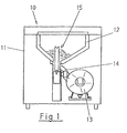
- FIG. 1 shows a device for the floating baking of food portions, called the fryer 10 below.
- the fryer 10 comprises a housing 11, in which a storage container 12 for fried food and the cooking device 13, which is connected via a conveying tube 14 to the reservoir 12, are received.
- suitable means such as a scoop tube 15
- portions are measured in the reservoir 12, passed into the conveying tube 14 and from there the cooking device 13, wherein after the cooking, the portions of the cooking device 13 are conveyed away.
- Fig. 2 shows a trained according to the invention cooking device 13 in longitudinal section.
- the cooking device 13 comprises an L-shaped support frame 16 with a vertical 17 and horizontal leg 18.
- the service drum 19 is formed as a closed-end and open-ended sleeve at the other end, in which the cooking drum 20 are inserted with discharge drum 21 inserted.
- the service drum 19, which is open at one end, is closed by a lid 22 which fixes the cooking drum 20 with discharge drum 21 in the axial direction in an immovable manner.
- a delivery chute 23 is provided, the downstream end of which engages through the lid 22.
- the service drum 19 is connected via supports 28 with the horizontal leg 18.
- the bottom 26 of the drum 20 and the bottom 27 of the service drum 19 is centrally penetrated by a drive shaft 29, which is connected on the side of the vertical leg 17 with the output 30 of an electric motor 31 which passes through the vertical leg 17.
- the free, projecting into the drum 20 stub shaft 32 is a plug-in coupling 34 connected to the inverter 33 which rotates about the fixed discharge drum 21.
- an electric heater 35 is inserted, which brings the Garfett 36 in the cooking drum 20 to a certain temperature and holds.
- the fill level and the temperature of the liquid cooking fat 36 are monitored by means of a Oelstandmessers 37 and thermostats 38 in the cooking drum 20.
- Trained as a hollow cylinder and closed on all sides cooking drum 20 is provided with a discharge pipe 39, are discharged with the evaporated cooking fat 36 and other volatile evaporation products from the cooking drum 20.
- the exhaust pipe 39 with its inlet end 40 is slidably inserted into the circumferential wall of the service drum 19 and the drum 20. If the cooking drum 20 are replaced, the exhaust pipe 39 is pulled back until its free end has passed through the peripheral wall of the cooking drum 20 and so has released the cooking drum 20 for axial displacement.
- the exhaust pipe 39 is inserted at the uppermost point of a perpendicular to the horizontal leg 18 in the peripheral walls of the cooking drum 20 and service drum 19.
- the turntable 33 connected to the plug-in coupling 34 of the stub shaft 32 consists of two axially spaced-apart rings 41, 42.
- the outer diameter of the rings 41, 42 corresponds approximately to the inner diameter of the cooking drum 20, so that the rings 41, 42 in the cooking drum 20 can rotate.
- the diameter of the Central recesses 43, 44 is slightly larger than the outer diameter of the discharge drum 21, so that the rings 41, 42 can rotate in the cooking drum 20 and the discharge drum 21.
- the grids 45 consist of adjacently arranged rods 46, which run perpendicular to the longitudinal axis of the Wenders 33 and by means of an inner support 47 and outer support 48, which are both parallel to the longitudinal axis of the Wenders 33, connected.
- the inner support 47 is located near the outer periphery of the central recess of the ring 41, 42, while the outer support 48 is located near the outer periphery of the rings 41, 42.
- the ends of the rods 46 connected to the inner support 47 have radiused cranks 49 protruding from the inner support 47.
- the peripheral wall of the service drum 19 and the cooking drum 20 have congruently arranged entry openings 50 for loading the cooking drum 20, in these entry openings 50, the delivery pipe 14 opens out.
- the discharge drum 21 Received in the cooking drum 20 is the discharge drum 21, which is axially concentric with the cooking drum 20.
- the discharge drum 21 is a hollow cylinder closed on both sides by end walls 51, 52. In the longitudinal direction, extending from one end wall 51, 52 to the other, in the peripheral wall of the discharge drum 21, a slot-shaped, the peripheral wall by cross-recess 53 is provided.
- the recess 53 opens onto the arranged in the interior of the discharge drum 21, box-shaped conveyor slide 23 off.
- the conveyor chute 23 is U-shaped in cross-section and the legs of the profile projecting in parallel are connected to the inner surface of the discharge drum 21 so that frying material falling onto the delivery chute 23 through the entry opening 50 can not enter the interior of the discharge drum 21.
- the conveyor chute 23 extends to the peripheral surface of the discharge drum 21 in the direction of front end wall 51 sloping inclined and passes through the front end wall 51 with an extension 54 which projects from the front end wall 51 standing at an angle. All parts of the discharge drum 21, ie front end wall 51 and rear end wall 52, the pipe extending therebetween and the conveyor chute 23 are releasably secured to each other so that the discharge drum 21 can be easily disassembled and reassembled for maintenance, e.g.
- the front end wall 51 of the discharge drum 21 is arranged in concentric arrangement and detachable on the inside (side of Gartrommelinneren) of the lid 55 of the cooking drum 20, wherein in the assembled state, the extension 54 of the conveyor slide 23 and the lid 22 and 55 passes.
- the fryer 10 is easy and quick to keep ready.
- the screws 25 are released and the pivot bracket 24 is brought out of engagement with the cover 22.
- the cover 22 is withdrawn from the service drum 19
- the cooking drum 20 with the spent cooking fat can now after extraction of the exhaust pipe 39 and releasing the plug-in coupling 34 pulled out as a unit from the service drum 19 and by a Gartrommel 20 are replaced with unused cooking fat by inserting into the service drum 19.
- the Dekkels 22 pivoting back the swivel bracket 24 and tightening the screws 25, the cooking drum 20 is fixed in the service drum 19 and ready for connection of the exhaust pipe 39 and the drive 31.
- the cooking drum 20 is, with the exception of the connection for the exhaust pipe 39, closed on all sides. Since the level of liquid Garfettes does not reach the connection opening for the exhaust pipe 39, this is, even closable opening, a grease loss-free handling of the cooking drum 20 in their exchange does not oppose. Is achieved with a cooking drum 20 of the described embodiment that on the occasion of their replacement, the interior of the service drum 19 can be maintained hygienically in perfect condition with simple means and without much time and ensure that the practically closed cooking drum 20 a Bratfettle the fryer or whose site would pollute is excluded. As the discharge drum 21 and the cooking drum 20 is made of detachably interconnected items that are easy to clean as such.
- the inlet opening 50 On the inside of the cooking drum 20, the inlet opening 50 by a means of a hinge (not shown) pivotable flap 57 is closed. In the closed position, it can be held for example by spring pressure.
- the inlet opening 50 is opened by portions which slide out of the conveyor tube 14 and open the flap 57. After passage of a portion, the flap returns to the closed position. It is achieved with the flap 57, that it prevents the oxygen access to the cooking drum 20 in the event of a fire of the shortening. In normal operation, however, prevents the flap 57, that evaporated frying fat in the direction of the reservoir 12 rises.
- the extension 54 of the conveyor chute 23 is covered by means of a closure 56 which, like the conveyor chute 23, is equally U-shaped in cross-section.
- the closure 56 can cover the extension 54 or pivot in last. so that the downstream end (front side) of the extension 54 and the longitudinal open surface of the extension 54 are closed.
- the closure 56 is pivoted to the downstream end wall of the discharge drum 21, which is penetrated by the conveyor chute 23. It is opened and closed by a drive (not shown), which can be operated electrically, hydraulically or pneumatically.
- the closure 56 is opened when dough is removed from the discharge drum 21, otherwise the extension 54 is closed.
- the closure 56 prevents evaporated shortening can escape from the cooking drum 20 via the discharge drum 21 from the fryer 10 in the environment, also prevents the closure 56 made from the outside entry in the shortening and in case of fire the closure 56 prevents oxygen access.
- a valve 58 is arranged, which is open in normal operation, automatically closes when developing a fire, so that an oxygen access is interrupted via the exhaust pipe.
Landscapes
- Engineering & Computer Science (AREA)
- Food Science & Technology (AREA)
- Frying-Pans Or Fryers (AREA)
Description
- Die Erfindung betrifft eine Fritiervorrichtung zum schwimmenden Backen von Lebens- und Genussmittelportionen, insbesondere in Stücken vereinzelter Portionen nach dem Oberbegriff des Patentanspruches 1.
- Unter schwimmend backen wird die Aufbereitung von Lebens- oder anderen Genussmitteln (folgend zusammengefasst Lebensmittel genannt) verstanden, die sich dadurch kennzeichnet, dass Lebensmittel in heissem Fett schwimmend gegart, d.h. für den Verzehr geeignet durchbacken werden. Für diese Art der Lebensmittelaufbereitung hat sich auch die Bezeichnung "fritieren", für Vorrichtungen zum Fritieren die der "Friteuse" durchgesetzt, die folgend in der Darstellung der Erfindung Verwendung findet. Die Friteuse nach der Erfindung ist insbesondere auf die Aufbereitung von Haufwerken aus vergleichsweise gleich grossen streifenförmigen Stücken ausgerichtet.
- Ein häufig zum Verzehr bestimmtes Haufwerk der beschriebenen Art wird aus Kartoffeln gebildet, das für den Verzehr durch Fritieren zubereitet wird. Allgemein bekannt sind solche Haufwerke unter der Bezeichnung "Pommes Frites Portionen".
- Bekannt ist eine Vorrichtung (CH 691 422 A5) zur Herstellung von Pommes Frites Portionen, die letztere ausgehend von einem rohen oder vorgebackenen Haufwerk selbsttätig herstellt. Dazu umfasst die bekannte Vorrichtung im wesentlichen einen Vorratsbehälter für ungegarte Pommes Frites und eine Fritiertrommel, wobei der Vorratsbehälter über eine Rohrverbindung mit der Fritiertrommel in Verbindung steht.
- Eine im Vorratsbehälter wirkende Schöpfeinrichtung bildet ein Haufwerk vorbestimmter Menge und fördert diese in das Rohr, welches das Haufwerk in die Fritiertrommel leitet. In der Fritiertrommel wird das Haufwerk in heissem Oel durchbacken und danach aus der Fritiertrommel gefördert.
- In der flüssiges Bratfett enthaltenden Fritiertrommel dreht ein Wender, der an seinem Umfang radial abragende und in gleicher Teilung am Umfang angeordnete Rechen umfasst, die zur Garung ein Haufwerk durch das heisse Bratfett leiten und anschliessend aus der Vorrichtung austragen. Dabei verbraucht sich das Bratfett und ist deshalb periodisch auszutauschen. Der Austausch erfolgt vermittels eines Ablasshahnes, der das verbrauchte Bratfett aus der Fritiertrommel austrägt, wobei anschliessend die Fritiertrornmel stirnseitig wieder aufgefüllt wird. Vor Auffüllung ist die Vorrichtung zu reinigen, was einen grossen Zeit- und Arbeitsaufwand bedeutet, um die Vorrichtung in hygienisch einwandfreiem Zustand zu halten, hinzu tritt die Gefahr des Verlustes von Backfett durch den Austausch.
- Hiervon ausgehend hat sich die Erfindung die Aufgabe gestellt, eine Fritiervorrichtung so auszugestalten, dass der Bratfettaustausch schnell und ohne Gefahr eines unbeabsichtigten Backfettverlustes vorgenommen werden kann und die Aufgabe wird erfindungsgemäss vermittels der kennzeichnenden Merkmale des Anspruches 1 gelöst.
- Weitere vorteilhafte Ausgestaltungen der erfindungsgemässen Lösung nach Patentanspruch 1 ergeben sich durch die Merkmale der dem Patentanspruch 1 folgenden Patentansprüche.
- Weitere Vorteile, Merkmale und Einzelheiten der Erfindung ergeben sich aus der folgenden Beschreibung eines bevorzugten Austührungsbeispieles und der Zeichnung, es stellen dar:
- Fig. 1
- Eine erfindungsgemäss ausgestattete Fritiervorrichtung in der Vorderansicht schematisch und im Schnitt dargestellt.
- Fig. 2
- Eine Fritiervorrichtung nach Fig. 1 in der Seitenansicht und im Schnitt.
- Fig. 3
- Eine Fritiertrommel in der Vorderansicht.
- Fig. 4
- Die Fritiertrommel gemäss Fig. 3 im Vertikalschnitt.
- Fig. 5
- Einen Wender in perspektivischer Darstellung.
- Fig. 1 zeigt eine Vorrichtung zum schwimmenden Backen von Lebensmittelportionen, folgend Fritiervorrichtung 10 genannt. Die Fritiervorrichtung 10 umfasst ein Gehäuse 11, in dem ein Vorratsbehälter 12 für Fritiergut und die Gareinrichtung 13, die über ein Förderrohr 14 mit dem Vorratsbehälter 12 verbunden ist, aufgenommen sind. Durch geeignete Mittel, beispielsweise ein Schöpfrohr 15, werden Portionen im Vorratsbehälter 12 abgemessen, in das Förderrohr 14 geleitet und von dort der Gareinrichtung 13 zugeleitet, wobei nach erfolgter Garung die Portionen aus der Gareinrichtung 13 abgefördert werden.
- Fig. 2 zeigt eine nach der Erfindung ausgebildete Gareinrichtung 13 im Längsschnitt. Die Gareinrichtung 13 umfasst einen L-förmigen Stützrahmen 16 mit einem senkrechten 17 und waagrechten Schenkel 18. Auf dem waagrechten Schenkel 18 stützen sich drei Trommeln 19, 20, 21, die Servicetrommel 19, die Gartrommel 20 und die Austragstrommel 21 ab. Die Servicetrommel 19 ist als einends geschlossene und anderenends offene Hülse ausgebildet, in der die Gartrommel 20 mit Austragstrommel 21 eingeschoben aufgenommen sind. Die einends offene Servicetrommel 19 ist mit einem Deckel 22 verschlossen, der die Gartommel 20 mit Austragstrommel 21 in axialer Richtung unverschieblich festlegt. In der Austragstrommel 21 ist eine Förderrutsche 23 vorgesehen, deren abstromseitiges Ende den Deckel 22 durchgreift. Gegen die offene Stirnfläche der Servicetrommel 19 gedrückt wird der Deckel 22 von vorzugsweise drei Schwenkbügel 24, die einends schwenkbar am senkrechten Schenkel 17 angelenkt sind und anderenends an ihren freien Enden vermittels Schrauben 25 den Deckel 22 gegen die ringförmige Stirnfläche der Servicetrommel drücken. Die Servicetrommel 19 ist über Stützen 28 mit dem waagrechten Schenkel 18 verbunden. Der Boden 26 der Gartrommel 20 und der Boden 27 der Servicetrommel 19 wird mittig von einer Antriebswelle 29 durchgriffen, die auf Seiten des senkrechten Schenkels 17 mit dem Abtrieb 30 eines Elektromotors 31, der den senkrechten Schenkel 17 durchgreift, verbunden ist. Der freie, in die Gartrommel 20 ragende Wellenstumpf 32 ist über eine Steckkupplung 34 mit dem Wender 33 verbunden, der sich um die feststehende Austragstrommel 21 dreht.
- In die Umfangswandung der Servicetrommel 19, vorzugsweise in ihre parallel zum waagrechten Schenkel 18 verlaufende untere Hälfte, ist eine elektrische Heizung 35 eingelassen, die das Garfett 36 in der Gartrommel 20 auf eine bestimmte Temperatur bringt und hält. Der Füllstand und die Temperatur des flüssigen Garfettes 36 werden vermittels eines Oelstandmessers 37 und Thermostaten 38 in der Gartrommel 20 überwacht.
- Die als Hohlzylinder ausgebildete und allseits geschlossene Gartrommel 20 ist mit einem Abzugsrohr 39 versehen, mit dem verdampftes Garfett 36 und andere flüchtige Verdampfungsprodukte aus der Gartrommel 20 abgeführt werden. Das Abzugsrohr 39 mit seinem Eintrittsende 40 ist verschiebbar in die Umfangswandung der Servicetrommel 19 und die der Gartrommel 20 eingelassen. Soll die Gartrommel 20 ausgewechselt werden, wird das Abzugsrohr 39 soweit zurückgezogen, bis sein freies Ende die Umfangswandung der Gartrommel 20 durchfahren und so die Gartrommel 20 für eine axiale Verschiebung freigegeben hat. Bevorzugt ist das Abzugsrohr 39 am obersten Punkt einer Senkrechten zum waagrechten Schenkel 18 in die Umfangswandungen der Gartrommel 20 und Servicetrommel 19 eingelassen. Gemäss Fig. 5 besteht der mit der Steckkupplung 34 des Wellenstumpfes 32 verbundene Wender 33 aus zwei axial zueinander beabstandeten Ringen 41, 42. Der äussere Durchmesser der Ringe 41, 42 entspricht etwa dem Innendurchmesser der Gartrommel 20, so dass sich die Ringe 41, 42 in der Gartrommel 20 drehen können. Der Durchmesser der mittigen Ausnehmungen 43, 44 ist etwas grösser als der Aussendurchmesser der Austragstrommel 21, so dass sich die Ringe 41, 42 in der Gartrommel 20 und um die Austragstrommel 21 drehen können. Zwischen den Ringen 41, 42 sind in gleichmässiger Teilung mindestens zwei, vorzugsweise fünf, sich axial erstreckende, die Ringe 41, 42 miteinander fest verbundene Gitter 45 vorgesehen. Die Gitter 45 bestehen aus nebeneinander beabstandet angeordneten Stäben 46, die senkrecht zur Längsachse des Wenders 33 verlaufen und vermittels einem inneren Träger 47 und äusseren Träger 48, die beide parallel zur Längsachse des Wenders 33 verlaufen, verbunden sind. Der innere Träger 47 befindet sich nahe dem äusseren Umfang der mittigen Ausnehmung des Ringes 41, 42, während der äussere Träger 48 sich nahe dem äusseren Umfang der Ringe 41, 42 befindet. Die mit dem inneren Träger 47 verbundenen Enden der Stäbe 46 weisen radiusförmige, von dem inneren Träger 47 abragende Kröpfungen 49 auf. Die Umfangswandung der Servicetrommel 19 und die der Gartrommel 20 weisen deckungsgleich angeordnete Eintragsöffnungen 50 zur Beschikkung der Gartrommel 20 auf, in diese Eintragsöffnungen 50 mündet das Förderrohr 14 aus.
- In der Gartrommel 20 aufgenommen ist die Austragstrommel 21, die axial konzentrisch zur Gartrommel 20 verläuft. Die Austragstrommel 21 ist ein beidseits durch Stirnwandungen 51, 52 verschlossener Hohlzylinder. In Längsrichtung, von einer Stirnwand 51, 52 zur anderen verlaufend, ist in der Umfangswandung der Austragstrommel 21 eine schlitzförmige, die Umfangswandung durchgreifende Ausnehmung 53 vorgesehen. Die Ausnehmung 53 mündet auf die im Inneren der Austragstrommel 21 angeordnete, kastenförmige Förderrutsche 23 aus. Die Förderrutsche 23 ist im Querschnitt U-förmig ausgebildet und die parallel aufragenden Schenkel des Profils sind mit der inneren Oberfläche der Austragstrommel 21 verbunden, so dass durch die Eintragsöffnung 50 auf die Förderrutsche 23 fallendes Fritiergut nicht in das Innere der Austragstrommel 21 gelangen kann. Die Förderrutsche 23 verläuft zur Umfangsfläche der Austragstrommel 21 in Richtung auf vordere Stirnwand 51 abfallend geneigt und durchgreift die vordere Stirnwand 51 mit einer Verlängerung 54, die von der vorderen Stirnwand 51 unter einem Winkel stehend abragt. Alle Teile der Austragstrommel 21, also vordere Stirnwand 51 und hintere Stirnwand 52, das sich dazwischen erstreckende Rohr und die Förderrutsche 23 sind lösbar aneinander befestigt, so dass die Austragstrommel 21 zu Unterhalts-, beispielsweise Reinigungszwecken, leicht auseinandergenommen und wieder zusammengesetzt werden kann. Die vordere Stirnwand 51 der Austragstrommel 21 ist in konzentrischer Anordnung und lösbar auf der Innenseite (Seite zum Gartrommelinneren) des Deckels 55 der Gartrommel 20 angeordnet, wobei im Montagezustand die Verlängerung 54 der Förderrutsche 23 auch die Deckel 22 und 55 durchläuft.
- Aus Vorstehendem ist offensichtlich, dass die Fritiervorrichtung 10 einfach und schnell betriebsbereit zu halten ist. Bei Wechsel des Garfettes 36 werden die Schrauben 25 gelöst und die Schwenkbügel 24 ausser Eingriff mit dem Deckel 22 gebracht. Folgend wird der Deckel 22 von der Servicetrommel 19 abgezogen, die Gartrommel 20 mit dem verbrauchten Garfett kann nun nach Ausfahren des Abzugsrohres 39 und Lösen der Steckkupplung 34 als eine Einheit aus der Servicetrommel 19 herausgezogen und durch eine Gartrommel 20 mit unverbrauchtem Garfett durch Einschieben in die Servicetrommel 19 ersetzt werden. Durch Aufbringen des Dekkels 22, Rückschwenken der Schwenkbügel 24 und Anziehen der Schrauben 25 ist die Gartrommel 20 in der Servicetrommel 19 festgelegt und nach Anschluss des Abzugsrohres 39 und des Antriebes 31 betriebsbereit. Die Gartrommel 20 ist, mit Ausnahme des Anschlusses für das Abzugsrohr 39, allseits geschlossen. Da der Stand flüssigen Garfettes nicht bis zur Anschlussöffnung für das Abzugsrohr 39 reicht, steht diese, auch verschliessbare Öffnung, einer fettverlustfreien Handhabung der Gartrommel 20 bei deren Austausch nicht entgegen. Erreicht wird mit einer Gartrommel 20 der beschriebenen Ausgestaltung, dass anlässlich deren Austausch das Innere der Servicetrommel 19 mit einfachen Mitteln und ohne grossen Zeitaufwand hygienisch in einwandfreiem Zustand gehalten und sichergestellt werden kann, dass durch die praktisch geschlossene Gartrommel 20 ein Bratfettverlust, der die Fritiervorrichtung oder deren Aufstellungsort verschmutzen würde, ausgeschlossen wird. Wie die Austragstrommel 21 ist auch die Gartrommel 20 aus lösbar miteinander verbundenen Einzelteilen hergestellt, die als solche einfach zu reinigen sind. Mit der Erfindung wird über die Ausgestaltung der Aufnahme einer Gartrommel in eine Servicetrommel ein einfacher und schneller Ein- und Ausbau der Gartrommel und aufgrund ihrer allseits geschlossenen Bauweise eine fettverlustfreie Montage, d.h. Austausch erreicht. Erreicht mit der Erfindung ist auch, dass eine bezüglich ihres Füllstandes mit Bratfett allseits geschlossene Gartrommel zum Zwecke der Reinigung ihrer Bestandteile leicht zerlegbar ist.
- Auf der Innenseite der Gartrommel 20 ist die Eintrittsöffnung 50 durch eine vermittels eines Scharnieres (nicht gezeigt) schwenkbare Klappe 57 verschlossen. In Schliessstellung kann sie beispielsweise durch Federdruck gehalten werden. Geöffnet wird die Eintrittsöffnung 50 durch aus dem Förderrohr 14 nachrutschende Portionen, die die Klappe 57 aufschwenken. Nach Durchtritt einer Portion geht die Klappe in Schliessstellung zurück. Erreicht wird mit der Klappe 57, dass sie im Falle eines Brandes des Backfettes den Sauerstoffzutritt zur Gartrommel 20 unterbindet. Im Normalbetrieb dagegen verhindert die Klappe 57, dass verdunstetes Bratfett in Richtung auf den Vorratsbehälter 12 aufsteigt. Die Verlängerung 54 der Förderrutsche 23 ist vermittels eines Verschlusses 56 abgedeckt, der wie die Förderrutsche 23 gleichermassen im Querschnitt U-förmig ausgebildet ist. Je nach Bemessung des Verschlusses 56 kann er die Verlängerung 54 überdecken oder in letzte einschwenken. so dass das abstromseitige Ende (Stirnseite) der Verlängerung 54 und die längslaufende offene Fläche der Verlängerung 54 verschlossen sind. Der Verschluss 56 ist an die abstromseitige Stirnwand der Austragstrommel 21, die von der Förderrutsche 23 durchgriffen wird, schwenkbar angelenkt. Geöffnet und geschlossen wird er durch einen Antrieb (nicht gezeigt), der elektrisch, hydraulisch oder pneumatisch betreibbar sein kann. Geöffnet wird der Verschluss 56 wenn Backgut aus der Austragstrommel 21 abgefördert wird, ansonsten ist die Verlängerung 54 geschlossen. Durch den Verschluss 56 wird verhindert, dass verdunstetes Backfett aus der Gartrommel 20 über die Austragstrommel 21 aus der Fritiervorrichtung 10 in die Umgebung entweichen kann, ferner verhindert der Verschluss 56 einen von aussen vorgenommenen Eintrag in das Backfett und im Brandfall verhindert der Verschluss 56 einen Sauerstoffzutritt. Im Abzugsrohr 39 ist ein Ventil 58 angeordnet, das im Normalbetrieb offen ist, sich bei Entwicklung eines Brandes selbsttätig schliesst, so dass ein Sauerstoffzutritt über das Abzugsrohr unterbrochen ist.
Claims (8)
- Fritiervorrichtung zum schwimmenden Backen von Lebens- und Genussmittelportionen, insbesondere in Stücken vereinzelter Portionen, umfassend einen Vorratsbehälter und eine über ein Förderrohr mit dem Vorratsbehälter verbundene, verflüssigtes Bratfett enthaltene Gartrommel mit darin drehend aufgenommenen, gegarten Portionen in eine Austragstrommel mit abfördernder Förderrutsche fördernden Wender, dadurch gekennzeichnet, dass die Gartrommel (20) als ein allseits geschlossener Hohlzylinder ausgebildet und axial verschiebbar in einer Servicetrommel (19) aufgenommen ist.
- Fritiervorrichtung nach Anspruch 1, dadurch gekennzeichnet, dass in der Gartrommel (20) ein Backgut aus der Gartrommel (20) abfördernde Austragstrommel (21) und ein in die Austragstrommel (21) drehend fördernder Wender (33) angeordnet ist.
- Fritiervorrichtung nach Anspruch 2, dadurch gekennzeichnet, dass der Wender (33) über eine Steckkupplung (34) mit dem Abtrieb (30) eines Elektromotors (31) verbunden ist.
- Fritiervorrichtung nach Anspruch 2, dadurch gekennzeichnet, dass die Austragstrommel (21) eine schlitzförmige Ausnehmung (53) mit einer sich an die Ausnehmung (53) anschliessenden Förderrutsche (23) aufweist.
- Fritiervorrichtung nach Anspruch 4, dadurch gekennzeichnet, dass die Förderrutsche (23) als ein U-Profil ausgebildet ist.
- Fritiervorrichtung nach Anspruch 5, dadurch gekennzeichnet, dass parallele Schenkel des U-Profiles mit der inneren Oberfläche des rohrförmigen Teiles der Austragstrommel (21) in Eingriff stehen.
- Fritiervorrichtung nach einem der Ansprüche 4 bis 6, dadurch gekennzeichnet, dass die abwärts geneigte Förderrutsche (23) mit einer Verlängerung (54) einen Deckel (55) der Gartrommel (20) und einen Deckel (22) der Servicetrommel (19) durchgreift.
- Fritiervorrichtung nach einem der Ansprüche 1 bis 7, dadurch gekennzeichnet, dass die Gartrommel (20) und die Austragstrommel (21) in ihre Einzelteile zerlegbar ausgebildet sind.
Applications Claiming Priority (3)
| Application Number | Priority Date | Filing Date | Title |
|---|---|---|---|
| CH138602 | 2002-08-09 | ||
| CH01386/02A CH696057A5 (de) | 2002-08-09 | 2002-08-09 | Fritiervorrichtung. |
| PCT/CH2003/000512 WO2004014206A1 (de) | 2002-08-09 | 2003-07-28 | Fritiervorrichtung |
Publications (2)
| Publication Number | Publication Date |
|---|---|
| EP1528884A1 EP1528884A1 (de) | 2005-05-11 |
| EP1528884B1 true EP1528884B1 (de) | 2007-01-10 |
Family
ID=31501645
Family Applications (1)
| Application Number | Title | Priority Date | Filing Date |
|---|---|---|---|
| EP03783890A Expired - Lifetime EP1528884B1 (de) | 2002-08-09 | 2003-07-28 | Fritiervorrichtung |
Country Status (7)
| Country | Link |
|---|---|
| US (1) | US7617765B2 (de) |
| EP (1) | EP1528884B1 (de) |
| AU (1) | AU2003246503A1 (de) |
| CA (1) | CA2495278C (de) |
| CH (1) | CH696057A5 (de) |
| DE (1) | DE50306268D1 (de) |
| WO (1) | WO2004014206A1 (de) |
Families Citing this family (3)
| Publication number | Priority date | Publication date | Assignee | Title |
|---|---|---|---|---|
| ES2359663T3 (es) * | 2007-04-13 | 2011-05-25 | Ulrich Maurer | Disposición de freidora. |
| CN105454340B (zh) * | 2016-01-08 | 2018-07-17 | 姜俊凭 | 一种冷冻食品的自动油炸设备 |
| CH714096A2 (de) | 2017-08-29 | 2019-03-15 | Ffm Projekt Ag | Dosierapparat. |
Family Cites Families (10)
| Publication number | Priority date | Publication date | Assignee | Title |
|---|---|---|---|---|
| EP0379755A1 (de) * | 1989-01-24 | 1990-08-01 | Hobart Corporation | Rotierender Ofen mit kontinuierlicher Förderung und Kochraum dafür |
| DE3904008A1 (de) * | 1989-02-10 | 1990-08-23 | Margot S N C Di Fausto Negri & | Vorrichtung zum dauerkochen von portionen bzw. mengen von lebensmitteln und abgabe bzw. entnahme dieser mengen |
| US5341729A (en) * | 1993-09-23 | 1994-08-30 | Lyco Manufacturing, Inc. | Discharge for rotating drum blanchers and coolers |
| CH691422A5 (de) * | 1994-12-21 | 2001-07-31 | Rahel Mutzner | Fritiervorrichtung mit Schleuse im Förderrohr. |
| IT1273923B (it) * | 1994-12-23 | 1997-07-11 | Rtm S P A | Struttura di friggitrice |
| US6205913B1 (en) * | 2000-02-14 | 2001-03-27 | Lyco Manufacturing Inc. | Rotary drum blancher for cooking food |
| US6523457B1 (en) * | 2001-08-24 | 2003-02-25 | Lectrix, Llc. | Pasta machine |
| ITMI20021794A1 (it) * | 2002-08-06 | 2004-02-07 | Techfood S N C Di Iori E Castagnetti | Macchina automatica per la cottura di pasta all'italiana |
| US6834577B2 (en) * | 2003-04-05 | 2004-12-28 | Zhaoxia Xu | Automatic fry apparatus |
| CH697333B1 (de) * | 2004-03-22 | 2008-08-29 | Ulrich Maurer | Garbehälter. |
-
2002
- 2002-08-09 CH CH01386/02A patent/CH696057A5/de not_active IP Right Cessation
-
2003
- 2003-07-28 WO PCT/CH2003/000512 patent/WO2004014206A1/de not_active Ceased
- 2003-07-28 DE DE50306268T patent/DE50306268D1/de not_active Expired - Lifetime
- 2003-07-28 AU AU2003246503A patent/AU2003246503A1/en not_active Abandoned
- 2003-07-28 CA CA2495278A patent/CA2495278C/en not_active Expired - Lifetime
- 2003-07-28 US US10/523,962 patent/US7617765B2/en not_active Expired - Fee Related
- 2003-07-28 EP EP03783890A patent/EP1528884B1/de not_active Expired - Lifetime
Also Published As
| Publication number | Publication date |
|---|---|
| US7617765B2 (en) | 2009-11-17 |
| WO2004014206A1 (de) | 2004-02-19 |
| US20060021516A1 (en) | 2006-02-02 |
| CA2495278A1 (en) | 2004-02-19 |
| CA2495278C (en) | 2011-06-21 |
| DE50306268D1 (de) | 2007-02-22 |
| CH696057A5 (de) | 2006-12-15 |
| AU2003246503A1 (en) | 2004-02-25 |
| EP1528884A1 (de) | 2005-05-11 |
Similar Documents
| Publication | Publication Date | Title |
|---|---|---|
| DE1574196A1 (de) | Automat zum Verkaufen von frittierten Nahrungsmitteln | |
| EP1528884B1 (de) | Fritiervorrichtung | |
| DE9116225U1 (de) | Vorrichtung zum Grillen von Bratgut | |
| DE2439570A1 (de) | Nichttropfendes grillrost | |
| DE69817166T2 (de) | Koch-methode und apparat | |
| EP1579795B1 (de) | Garbehälter | |
| DE3102134C2 (de) | Maischetank | |
| DE202008012299U1 (de) | Grill | |
| DE1803466A1 (de) | Garten- und Partygrill | |
| DE2323133A1 (de) | Vorrichtung zum frittieren von stueckigen nahrungsmitteln | |
| DE4401281C1 (de) | Gargerät für stückiges Gargut | |
| CH691423A5 (de) | Oelablassvorrichtung für eine Fritiertrommel. | |
| WO1980000654A1 (fr) | Grill pour rotir, faire des toasts ou rechauffer | |
| CH691422A5 (de) | Fritiervorrichtung mit Schleuse im Förderrohr. | |
| DE202017107371U1 (de) | Vorrichtung zum Grillen von Lebensmitteln, insbesondere Fleischerzeugnissen | |
| DE102004001896B4 (de) | Einrichtung zum Grillen von Fleischspeisen | |
| AT295070B (de) | Holzkohlengrill | |
| EP3108780B1 (de) | Vorrichtung zum garen von lebensmitteln | |
| WO2007056871A1 (de) | Vorrichtung zum grillen von speisen | |
| DE20220336U1 (de) | Drehspieß-Grillgerät | |
| DE202020104568U1 (de) | Vorrichtung zum Grillen von Lebensmitteln | |
| DE102006001296A1 (de) | Gargerät und Verfahren zum Begießen eines Garguts | |
| DE202013009488U1 (de) | Mobiler Räucher-Grill-Ofen | |
| DE10249094A1 (de) | Drehspieß-Grillgerät | |
| DE4030348A1 (de) | Grillgeraet |
Legal Events
| Date | Code | Title | Description |
|---|---|---|---|
| PUAI | Public reference made under article 153(3) epc to a published international application that has entered the european phase |
Free format text: ORIGINAL CODE: 0009012 |
|
| 17P | Request for examination filed |
Effective date: 20050303 |
|
| AK | Designated contracting states |
Kind code of ref document: A1 Designated state(s): AT BE BG CH CY CZ DE DK EE ES FI FR GB GR HU IE IT LI LU MC NL PT RO SE SI SK TR |
|
| AX | Request for extension of the european patent |
Extension state: AL LT LV MK |
|
| 17Q | First examination report despatched |
Effective date: 20050530 |
|
| DAX | Request for extension of the european patent (deleted) | ||
| GRAP | Despatch of communication of intention to grant a patent |
Free format text: ORIGINAL CODE: EPIDOSNIGR1 |
|
| GRAS | Grant fee paid |
Free format text: ORIGINAL CODE: EPIDOSNIGR3 |
|
| GRAA | (expected) grant |
Free format text: ORIGINAL CODE: 0009210 |
|
| AK | Designated contracting states |
Kind code of ref document: B1 Designated state(s): AT BE BG CH CY CZ DE DK EE ES FI FR GB GR HU IE IT LI LU MC NL PT RO SE SI SK TR |
|
| PG25 | Lapsed in a contracting state [announced via postgrant information from national office to epo] |
Ref country code: DK Free format text: LAPSE BECAUSE OF FAILURE TO SUBMIT A TRANSLATION OF THE DESCRIPTION OR TO PAY THE FEE WITHIN THE PRESCRIBED TIME-LIMIT Effective date: 20070110 Ref country code: SI Free format text: LAPSE BECAUSE OF FAILURE TO SUBMIT A TRANSLATION OF THE DESCRIPTION OR TO PAY THE FEE WITHIN THE PRESCRIBED TIME-LIMIT Effective date: 20070110 Ref country code: FI Free format text: LAPSE BECAUSE OF FAILURE TO SUBMIT A TRANSLATION OF THE DESCRIPTION OR TO PAY THE FEE WITHIN THE PRESCRIBED TIME-LIMIT Effective date: 20070110 Ref country code: NL Free format text: LAPSE BECAUSE OF FAILURE TO SUBMIT A TRANSLATION OF THE DESCRIPTION OR TO PAY THE FEE WITHIN THE PRESCRIBED TIME-LIMIT Effective date: 20070110 |
|
| REG | Reference to a national code |
Ref country code: GB Ref legal event code: FG4D Free format text: NOT ENGLISH |
|
| REG | Reference to a national code |
Ref country code: IE Ref legal event code: FG4D Free format text: LANGUAGE OF EP DOCUMENT: GERMAN |
|
| REF | Corresponds to: |
Ref document number: 50306268 Country of ref document: DE Date of ref document: 20070222 Kind code of ref document: P |
|
| PG25 | Lapsed in a contracting state [announced via postgrant information from national office to epo] |
Ref country code: SE Free format text: LAPSE BECAUSE OF FAILURE TO SUBMIT A TRANSLATION OF THE DESCRIPTION OR TO PAY THE FEE WITHIN THE PRESCRIBED TIME-LIMIT Effective date: 20070410 |
|
| PG25 | Lapsed in a contracting state [announced via postgrant information from national office to epo] |
Ref country code: BG Free format text: LAPSE BECAUSE OF EXPIRATION OF PROTECTION Effective date: 20070411 |
|
| PG25 | Lapsed in a contracting state [announced via postgrant information from national office to epo] |
Ref country code: ES Free format text: LAPSE BECAUSE OF FAILURE TO SUBMIT A TRANSLATION OF THE DESCRIPTION OR TO PAY THE FEE WITHIN THE PRESCRIBED TIME-LIMIT Effective date: 20070421 |
|
| GBT | Gb: translation of ep patent filed (gb section 77(6)(a)/1977) |
Effective date: 20070516 |
|
| PG25 | Lapsed in a contracting state [announced via postgrant information from national office to epo] |
Ref country code: PT Free format text: LAPSE BECAUSE OF FAILURE TO SUBMIT A TRANSLATION OF THE DESCRIPTION OR TO PAY THE FEE WITHIN THE PRESCRIBED TIME-LIMIT Effective date: 20070611 |
|
| NLV1 | Nl: lapsed or annulled due to failure to fulfill the requirements of art. 29p and 29m of the patents act | ||
| ET | Fr: translation filed | ||
| REG | Reference to a national code |
Ref country code: CH Ref legal event code: NV Representative=s name: HIEBSCH & PEEGE AG PATENTANWAELTE |
|
| PLBE | No opposition filed within time limit |
Free format text: ORIGINAL CODE: 0009261 |
|
| STAA | Information on the status of an ep patent application or granted ep patent |
Free format text: STATUS: NO OPPOSITION FILED WITHIN TIME LIMIT |
|
| PG25 | Lapsed in a contracting state [announced via postgrant information from national office to epo] |
Ref country code: SK Free format text: LAPSE BECAUSE OF FAILURE TO SUBMIT A TRANSLATION OF THE DESCRIPTION OR TO PAY THE FEE WITHIN THE PRESCRIBED TIME-LIMIT Effective date: 20070110 |
|
| 26N | No opposition filed |
Effective date: 20071011 |
|
| REG | Reference to a national code |
Ref country code: CH Ref legal event code: NV Representative=s name: RIEDERER HASLER & PARTNER PATENTANWAELTE AG |
|
| PG25 | Lapsed in a contracting state [announced via postgrant information from national office to epo] |
Ref country code: CZ Free format text: LAPSE BECAUSE OF FAILURE TO SUBMIT A TRANSLATION OF THE DESCRIPTION OR TO PAY THE FEE WITHIN THE PRESCRIBED TIME-LIMIT Effective date: 20070110 Ref country code: RO Free format text: LAPSE BECAUSE OF FAILURE TO SUBMIT A TRANSLATION OF THE DESCRIPTION OR TO PAY THE FEE WITHIN THE PRESCRIBED TIME-LIMIT Effective date: 20070110 |
|
| PG25 | Lapsed in a contracting state [announced via postgrant information from national office to epo] |
Ref country code: MC Free format text: LAPSE BECAUSE OF NON-PAYMENT OF DUE FEES Effective date: 20070731 Ref country code: GR Free format text: LAPSE BECAUSE OF FAILURE TO SUBMIT A TRANSLATION OF THE DESCRIPTION OR TO PAY THE FEE WITHIN THE PRESCRIBED TIME-LIMIT Effective date: 20070411 |
|
| PG25 | Lapsed in a contracting state [announced via postgrant information from national office to epo] |
Ref country code: EE Free format text: LAPSE BECAUSE OF FAILURE TO SUBMIT A TRANSLATION OF THE DESCRIPTION OR TO PAY THE FEE WITHIN THE PRESCRIBED TIME-LIMIT Effective date: 20070110 |
|
| PG25 | Lapsed in a contracting state [announced via postgrant information from national office to epo] |
Ref country code: CY Free format text: LAPSE BECAUSE OF FAILURE TO SUBMIT A TRANSLATION OF THE DESCRIPTION OR TO PAY THE FEE WITHIN THE PRESCRIBED TIME-LIMIT Effective date: 20070110 |
|
| PG25 | Lapsed in a contracting state [announced via postgrant information from national office to epo] |
Ref country code: LU Free format text: LAPSE BECAUSE OF NON-PAYMENT OF DUE FEES Effective date: 20070728 |
|
| PG25 | Lapsed in a contracting state [announced via postgrant information from national office to epo] |
Ref country code: HU Free format text: LAPSE BECAUSE OF FAILURE TO SUBMIT A TRANSLATION OF THE DESCRIPTION OR TO PAY THE FEE WITHIN THE PRESCRIBED TIME-LIMIT Effective date: 20070711 Ref country code: TR Free format text: LAPSE BECAUSE OF FAILURE TO SUBMIT A TRANSLATION OF THE DESCRIPTION OR TO PAY THE FEE WITHIN THE PRESCRIBED TIME-LIMIT Effective date: 20070110 |
|
| REG | Reference to a national code |
Ref country code: FR Ref legal event code: PLFP Year of fee payment: 14 |
|
| PGFP | Annual fee paid to national office [announced via postgrant information from national office to epo] |
Ref country code: IE Payment date: 20160722 Year of fee payment: 14 Ref country code: GB Payment date: 20160721 Year of fee payment: 14 Ref country code: DE Payment date: 20160722 Year of fee payment: 14 Ref country code: CH Payment date: 20160721 Year of fee payment: 14 Ref country code: IT Payment date: 20160725 Year of fee payment: 14 |
|
| PGFP | Annual fee paid to national office [announced via postgrant information from national office to epo] |
Ref country code: FR Payment date: 20160721 Year of fee payment: 14 Ref country code: AT Payment date: 20160721 Year of fee payment: 14 |
|
| PGFP | Annual fee paid to national office [announced via postgrant information from national office to epo] |
Ref country code: BE Payment date: 20160720 Year of fee payment: 14 |
|
| REG | Reference to a national code |
Ref country code: DE Ref legal event code: R119 Ref document number: 50306268 Country of ref document: DE |
|
| REG | Reference to a national code |
Ref country code: CH Ref legal event code: PL |
|
| REG | Reference to a national code |
Ref country code: AT Ref legal event code: MM01 Ref document number: 350913 Country of ref document: AT Kind code of ref document: T Effective date: 20170728 |
|
| GBPC | Gb: european patent ceased through non-payment of renewal fee |
Effective date: 20170728 |
|
| REG | Reference to a national code |
Ref country code: IE Ref legal event code: MM4A |
|
| REG | Reference to a national code |
Ref country code: FR Ref legal event code: ST Effective date: 20180330 |
|
| PG25 | Lapsed in a contracting state [announced via postgrant information from national office to epo] |
Ref country code: DE Free format text: LAPSE BECAUSE OF NON-PAYMENT OF DUE FEES Effective date: 20180201 Ref country code: CH Free format text: LAPSE BECAUSE OF NON-PAYMENT OF DUE FEES Effective date: 20170731 Ref country code: GB Free format text: LAPSE BECAUSE OF NON-PAYMENT OF DUE FEES Effective date: 20170728 Ref country code: IE Free format text: LAPSE BECAUSE OF NON-PAYMENT OF DUE FEES Effective date: 20170728 Ref country code: LI Free format text: LAPSE BECAUSE OF NON-PAYMENT OF DUE FEES Effective date: 20170731 |
|
| PG25 | Lapsed in a contracting state [announced via postgrant information from national office to epo] |
Ref country code: AT Free format text: LAPSE BECAUSE OF NON-PAYMENT OF DUE FEES Effective date: 20170728 Ref country code: FR Free format text: LAPSE BECAUSE OF NON-PAYMENT OF DUE FEES Effective date: 20170731 |
|
| REG | Reference to a national code |
Ref country code: BE Ref legal event code: MM Effective date: 20170731 |
|
| PG25 | Lapsed in a contracting state [announced via postgrant information from national office to epo] |
Ref country code: IT Free format text: LAPSE BECAUSE OF NON-PAYMENT OF DUE FEES Effective date: 20170728 Ref country code: BE Free format text: LAPSE BECAUSE OF NON-PAYMENT OF DUE FEES Effective date: 20170731 |