EP1528690B1 - Spread spectrum system communication unit and its method for establishing high speed synchronization - Google Patents
Spread spectrum system communication unit and its method for establishing high speed synchronization Download PDFInfo
- Publication number
- EP1528690B1 EP1528690B1 EP03815726A EP03815726A EP1528690B1 EP 1528690 B1 EP1528690 B1 EP 1528690B1 EP 03815726 A EP03815726 A EP 03815726A EP 03815726 A EP03815726 A EP 03815726A EP 1528690 B1 EP1528690 B1 EP 1528690B1
- Authority
- EP
- European Patent Office
- Prior art keywords
- signal
- spread code
- carrier
- toggle
- received signal
- Prior art date
- Legal status (The legal status is an assumption and is not a legal conclusion. Google has not performed a legal analysis and makes no representation as to the accuracy of the status listed.)
- Expired - Lifetime
Links
Images


Classifications
-
- H—ELECTRICITY
- H04—ELECTRIC COMMUNICATION TECHNIQUE
- H04B—TRANSMISSION
- H04B1/00—Details of transmission systems, not covered by a single one of groups H04B3/00 - H04B13/00; Details of transmission systems not characterised by the medium used for transmission
- H04B1/69—Spread spectrum techniques
- H04B1/707—Spread spectrum techniques using direct sequence modulation
- H04B1/7073—Synchronisation aspects
- H04B1/7075—Synchronisation aspects with code phase acquisition
- H04B1/70757—Synchronisation aspects with code phase acquisition with increased resolution, i.e. higher than half a chip
-
- H—ELECTRICITY
- H04—ELECTRIC COMMUNICATION TECHNIQUE
- H04B—TRANSMISSION
- H04B1/00—Details of transmission systems, not covered by a single one of groups H04B3/00 - H04B13/00; Details of transmission systems not characterised by the medium used for transmission
- H04B1/69—Spread spectrum techniques
- H04B1/707—Spread spectrum techniques using direct sequence modulation
- H04B1/7073—Synchronisation aspects
- H04B1/7075—Synchronisation aspects with code phase acquisition
- H04B1/70751—Synchronisation aspects with code phase acquisition using partial detection
- H04B1/70753—Partial phase search
Definitions
- the present invention relates to an equipment for spread spectrum communication, particularly relates to an equipment realizing super-low-power long-distance communication and relates to a high-speed synchronization establishing method for spread spectrum communication.
- radio systems such as wireless LAN or mobile phones have been widely used.
- the radio systems have been improved day by day in order to transmit more information at a faster speed.
- the communication speed does not need to be high-speed.
- identification ability about transmission media is necessary to obtain super high sensitivity for long distance communication.
- the identification ability is dominated by a receiving bandwidth.
- a wider receiving bandwidth increases relatively natural noise power and the probability of radio interference with other communication. Therefore, an extremely narrow receiving bandwidth increases communicable distance relatively.
- the extremely narrow receiving bandwidth can reduces required power. For example, when the receiving bandwidth, approximately 20 kHz in general FM (Frequency Modulation) broadcasting, is narrowed to 1 Hz, the required power is reduced to one-to-twenty-thousand. One-to-twenty-thousand of 10 mW special-low power is 0.5 ⁇ m. When the receiving bandwidth of 10 W ham radio, which can communicate worldwide, is narrowed to 1 Hz, the required power is reduced to one-to-twenty-thousand, or to 0.5 mW
- an accuracy of the frequency of 150 MHz crystal oscillator is approximately 15 ppm; a frequency deviation of which is 3 kHz.
- This 3 kHz frequency deviation is 3,000 times larger than that of 1 Hz in the above example. Therefore, a carrier must be searched over the bandwidth corresponding to 1,000 channels even if every three frequency is used. Moreover, by just narrowing the receiving bandwidth, it is difficult to remove the radio interference in the conventional communication.
- the spread spectrum communication will be described concisely.
- CDMA Code Division Multiple Access
- Bluetooth personal computers
- wireless LAN Local Area Network
- the spread spectrum communication had two aspects.
- the one aspect was for a long-distance communication by very weak electric-wave for military or satellite use.
- the other one was for multiplex communication maintaining multiple communication paths at the same frequency.
- the former aspect is mainly used for GPS (Global Positioning System), now employed for car navigation systems; the latter one is mainly used for the other purpose.
- GPS Global Positioning System
- the spread spectrum communication reproduces an original carrier on the receiving end by multiplying a received signal by a spread signal.
- the spread signal applied for modulating (spreading) the original carrier on the transmitting end, is synchronized by shifting a phase of the spread signal by the time corresponding to transmission delay.
- To reproduce the original carrier as mentioned above is called “despread” or “demodulate”.
- the spread signal being multiplied must be shifted by the time corresponding to the transmission delay. Accordingly, in order to receive successfully on the receiving end without acknowledging the time of the transmission delay, trials of despreading (demodulating) operation is repeated while the spread code is slid little by little (for example, the shift amount which is to be provided to the spread code is increased in increments of one chip-time (the minimum time-unit of the spread code) with respect to the each trial step), and then feasibility of receiving is determined by checking the useful level of the reproduced carrier.
- a required time for synchronizing is roughly calculated by multiplying the period time of M-Sequence (Maximum Length Sequence) by the number of chips of M-Sequence, if M-Sequence is used as the spread code. For example, in a high-speed wireless LAN where the transmission speed is 11 Mbps and the spread code has the length corresponding to 11 chips, when the slide method is performed under the condition that the shift amount added by every trial step corresponds to one chip-time, the synchronization is established after 11 trials at the longest.
- the required time for one trial is 1.1 ⁇ s (0.1 ⁇ s x 11 chips).
- the required time for 11 trials is 12 ⁇ s (1.1 ⁇ s x 11 chips) in the slide method. In other words, the synchronization is established in such a short time.
- the required time for one trial is corresponding to 1, 023 chip-times (one period time of the spread code) at the minimum.
- the synchronization is established by 2, 046 slides (2,046 trials). Accordingly, the required time for synchronizing is corresponding to two-million-chip-time (1,023 chip-times x 2,046). The longest required time is 2 seconds and an average required time is 1 second in GPS where the chip-time is 1 ⁇ s.
- the required time for synchronizing will be considered when the spread spectrum communication, as mentioned above, is applied to "the narrowed occupied-bandwidth long-distance communication" and the slide method is performed.
- the required time for synchronizing is 200 s (0.1ms x two-million-chip-time). Therefore, an average time for synchronizing from the first receive to the first one-bit detection is 100 s; the longest time of that is 200 s.
- the slide method takes considerable time when the spread spectrum communication is applied to the narrowed occupied-bandwidth long-distance communication. Accordingly, an extra transmission time for synchronizing is required. However, a longer transmission time reduces electric-power-efficiency because it needs more electric power. Therefore, the super-low-power long-distance communication radio system cannot be realized by just applying the spread spectrum communication to the narrowed occupied-bandwidth long-distance communication (the first problem).
- the carrier wavelength of 150 MHz frequencies is 2 m
- the receiver recognizes five-lower frequencies than the 150 MHz frequencies (150 MHz - 5 Hz) or a five-higher frequencies than the 150 MHz frequencies (150 MHz + 5 Hz).
- the chip-time of the spread code is 0.1 ms, and the spread-code length is 1,023 chips; the phase is changed 0.5 Hz, or 180 degrees, during one period-time (0.1 s).
- the carrier frequency has deviation; for example, 150 MHz ⁇ 15ppm ( ⁇ 2.25 kHz) (standard Xtal), one chip-time of the spread code is 0.1 ms, and the spread-code length is 1,023 chips; when the carrier frequency is changed by 5 Hz, maintaining the synchronization is difficult; when the carrier frequency is changed by 10 Hz, it can be different communication.
- phase-modulation such as the spread spectrum communication
- the detection of a carrier level will fail.
- the carrier frequency must be known precisely for synchronizing the spread code. 450 trials are required for detecting the carrier included in ⁇ 2.25 kHz in increments of 10 Hz. Therefore, when the carrier frequency has deviation, synchronizing the spread code is practically difficult (the forth problem) .
- a high-speed correlation is performed by Surface Acoustic Wave (SAW) device or others as a hardware correlation (for example, Japanese Patent Application KOKAI Publication No. 09-64787 ).
- SAW Surface Acoustic Wave
- a long-time correlator is required physically.
- producing that kind of correlator is difficult (the fifth problem).
- the phase must be guaranteed throughout a repeated time of the spread code in order to establish the synchronization in the conventional method; since the conventional method knows the carrier frequency or the carrier speed; can corrects the phase shifts; prepares the spread code having a proper shift amount by using that the spread-code length is short; and repeats the steps of despread, Phase Detection, and Establishing Synchronization.
- the carrier frequency must be known precisely in order to synchronize the spread code, also the spread code must be synchronized in order to know the carrier frequency.
- EP 0 892 277 A2 discloses a global navigation satellite system (GNSS) receiver with blanked-PRN code correlation.
- the GNSS receiver includes a subsystem that reduces the adverse effects of multipath signals on punctual and early-minus-late correlation measurements by making the correlation measurements using a "blanked-PRN code.”
- the blanked-PRN code is all zeros except for adjacent positive and negative short pulses that occur at every code bit transition in a locally-generated PRN code. Using the blanked-PRN code, the receiver makes non-zero correlation measurements only near the code bit transitions in the local PRN code.
- the GNSS receiver includes blanked-PRN code logic that produces the blanked-PRN code from the locally-generated PRN code. The blanked-PRN code logic thus produces a code that is zero-valued except for the adjacent pulses.
- the blanked-PRN code logic produces the zero-valued portions of the code by selectively disabling the blanked-code correlators in between the code bit transitions in the local PRN code.
- the result is the same, namely, a system that produces non-zero correlation measurements near the code bit transitions in the local PRN code.
- VSG Variable Spreading Gain
- IPI Inter-Path Interference
- An object of the present invention is to provide an equipment for spread spectrum communication which enables to realize super-low-power long-distance communication, enables to establish the synchronization at a high-speed, and enables to synchronize the spread code even if the carrier frequency is not known precisely.
- Another object of the present invention is to provide a synchronization establishing method for the spread spectrum communication.
- Fig. 1 is a block diagram showing outline architecture of a receiver in a communications equipment of the present invention.
- the receiver comprises a toggle filter (a toggle detecting unit) 101, a received-signal toggle-signal storage unit 102, a cross-correlator (a cross-correlation unit) 103, a shift amount calculation unit 104, a demodulator (a demodulation unit) 105, a carrier inspection section 106, and a control unit 107.
- the equipment of the present invention is the equipment for the spread spectrum communication, and can communicate in the following condition.
- a signal transmitted or received on the equipment is outputted from a transmitter after a carrier is phase-modulated (spreaded) by a spread code.
- carrier modulation by spread code is performed by Binary Phase Shift Keying (BPSK).
- BPSK Binary Phase Shift Keying
- QPSK Quadrature Phase Shift Keying
- BPSK is superior to the others on anti-jamming performance.
- the receiver demodulates (despreads) the signal (the received signal) and extracts an original carrier (a carrier before spreaded on the transmitter end) from the received signal.
- the demodulation is performed by multiplying the received signal by the spread code (code-sequence being equivalent to the spread code applied for spreading the carrier on the transmitter end).
- code-sequence being equivalent to the spread code applied for spreading the carrier on the transmitter end.
- lots of toggle point in which the phase is changed 180 degrees as a result that the carrier is modulated by the spread code. Transition point
- the carrier and the spread code applied for multiplying for the demodulation must be synchronized.
- a phase lag is produced between the signal outputted from the transmitter end and the received signal by the relation with transmission-delay-time and such, and by the frequency deviation and such. Accordingly, the spread code must be shifted to an estimated synchronizing-position in order to synchronize lots of toggle point in the carrier of the received signal and the spread code applied for multiplying for the demodulation.
- estimate synchronizing-position is an estimated position where the spread code is synchronized by shifting in the received signal.
- ⁇ is a shift amount which is necessary for displacing the spread code to the estimated synchronizing-position.
- the equipment in the preferred embodiment preliminarily detects the estimated synchronizing-position from the waveform of the received signal (detecting a candidate of the toggle point in the received signal, and outputting the toggle signal) (the toggle filter 101); correlates between the toggle signal and the spread code (the cross-correlator 103) ; calculates candidates ( ⁇ 1, ⁇ 2%) of the shift amount ⁇ based on the correlation (the shift amount calculation unit 104); tries to despread with respect to the each candidate of the shift amount (the demodulator 105); and then checks the extracted carrier every time and determines the feasibility of receiving (demodulating) (the carrier inspection section 106).
- the received signal in the receiver of the equipment, is entered into the toggle filter 101 and the received-signal toggle-signal storage unit 102.
- the toggle filter 101 is configured with a FIR (Finite Impulse Response) digital filter.
- the toggle filter 101 can be configured with an IIR (Infinite Impulse Response) digital filter or a multiplier accumulator.
- the toggle filter 101 detects, after the received signal is entered, the candidate of the toggle point (a phase-change point) in the received signal on the carrier and produces the toggle signal. More specifically, the toggle filter 101 previously holds an expected signal (or a feature calculated from the expected signal), correlates between the entered received signal and the expected signal (or the feature calculated from the expected signal) held previously, detects the phase-change point in the carrier, produces the toggle signal based on detected value of the phase-change point, and then outputs the toggle signal.
- the received-signal toggle-signal storage unit 102 configured with memory is connected to the output end of the toggle filter 101. Accordingly, the toggle signal outputted from the toggle filter 101 as well as the received signal are entered into the received-signal toggle-signal storage unit 102. The entered received signal and the toggle signal are stored as a pair for post-processing.
- the cross-correlator 103 is connected to the output end of the received-signal toggle-signal storage unit 102.
- the cross-correlator 103 is configured with a DSP (Digital Signal Processor) or cross-correlating means including a Fourier transformation processor by hardware logic.
- DSP Digital Signal Processor
- the cross-correlator 103 correlates between the toggle signal (Fourier transformed value of the toggle signal) outputted from the received-signal toggle-signal storage unit 102 and the spread code (Fourier transformed value of the absolute value of differentiated value of the spread code), and outputs the correlation S (f).
- the cross-correlator 103 previously stores information, processed favorably for cross-correlating, about the spread code applied for demodulating the carrier.
- the information about the spread code is processed by the following procedure.
- a conjugate of the cross-correlation is obtained from a sequence of the absolute value ka(t) by performing Fourier transform.
- g(t) is the toggle signal entered into the cross-correlator 103 from the received-signal toggle-signal storage unit 102.
- the cross-correlator 103 performs Fourier transform to a sequence of the toggle signal g(t). FFT(g(t)) toG(f)
- the shift amount calculation unit 104 is connected to the output end of the cross-correlator 103.
- the shift amount calculation unit 104 performs inverse Fourier transform to the correlation S(f) outputted from cross-correlator 103 and obtains s(t).
- the shift amount calculation unit 104 assumes that the peak value of the s(t) is the shift amount ⁇ (the shift amount required for shifting the spread code to the estimated synchronizing-position) which is to be provided to the spread code, and outputs more than one candidate of the shift amount ⁇ ( ⁇ 1, ⁇ 2... ) in descending order of the value of the s(t).
- the present invention can process for a long time by applying Fourier transform, instead of applying the conventional Surface Acoustic Wave (SAW) device.
- SAW Surface Acoustic Wave
- the demodulator 105 is connected to the output end of the received signal of the received-signal toggle-signal storage unit 102.
- the demodulator 105 demodulates the received signals by multiplying the received signal outputted from the received-signal toggle-signal storage unit 102 by a shifted spread code.
- the spread code is shifted by providing the candidates of the shift amount ( ⁇ 1, ⁇ 2%) outputted from the shift amount calculation unit 104 to the spread code. More specifically, the spread code is shifted according to the value of the first candidate ⁇ 1 of the shift amount, then the spread code is despreaded experimentally. After that, the spread code is provided the candidates of the shift amount in order, such as the second candidate ⁇ 2 of the shift amount and the third candidate ⁇ 3 of the shift amount. Then, repeatedly, the spread code is despreaded experimentally whenever the spread code is provided the candidates. Whenever the spread code is despreaded experimentally, a demodulated received-signal (a demodulated signal) is outputted from the demodulator 105.
- a demodulated received-signal (a demodulated signal) is outputted from the demodulator 105.
- the carrier inspection section 106 is connected to the output end of the demodulator 105.
- the carrier inspection section 106 is configured with a Fourier transform unit or a filter.
- the carrier inspection section 106 detects a spectrum of the each demodulated signal outputted from the demodulator 105 per the candidate of the shift amount ( ⁇ 1, ⁇ 2%), inspects validity of the spectrum of the carrier, and determines the feasibility of the synchronization.
- control unit 107 is connected to the output end of the carrier inspection section 106. Concerning operations as mentioned above, the control unit 107 controls, based on the results output from the carrier inspection section 106, the toggle filter 101, the cross-correlator 103, and the shift amount calculation unit 104. Moreover, the control unit 107 produces the expected signal in the toggle filter 101, controls multiplex communication established by applying more than one different spread code to the mutual correlator 103, and controls others as well as operates as mentioned above.
- Fig. 2 is a drawing for explaining the expected signal held in the toggle filter 101 shown in Fig. 1 .
- the toggle filter 101 detects the candidate of the toggle point in the received signal on the carrier and outputs the toggle signal.
- the expected signal shown in Fig. 2 is a signal pattern referred comparatively (calculated correlatively) in order to detect the candidate of the toggle point.
- the expected signal held in the toggle filter 101 has length corresponding to two tip-times of the spread code. In the center of the length of the expected signal, toggle point is located where the phase reversed 180 degrees.
- the expected signal is produced as a model of a waveform of the toggle point expected to be in the carrier of the received signal after spreading the carrier by the spread code, and as a model of a partial waveform around the toggle point.
- the expected signal has length corresponding to two tip-times of the spread code so that it may not include the other toggle point around the toggle point located in the center ot the expected signal.
- the expected signal has length corresponding to two tip-times of the spread code as mentioned above (or the expected signal has length which is shorter than length corresponding to two tip-times of the spread code)
- the phase-change point shown by integral multiple of one chip-time can be detected as the candidate of the toggle point, instead the short phase-change point is detected as the candidate of the toggle point.
- a solid line and a dotted line show a real number part (cosine curve) and an imaginary number part (sine curve) of the expected signal respectively.
- the phase of these curves is shifted 90 degrees.
- the real number part and the imaginary number part are used as a useful expression for calculating complex number as mathematical technique for signal processing.
- Fig. 3 is a drawing for explaining an example of the expected signal of Fig. 2 transformed by window function.
- Fig. 3(a) is corresponding to Fig. 2 .
- Fig. 3(b) and Fig. 3(c) show waveforms of the expected signal which are transformed by multiplying the window function throughout the expected signal after the toggle point of Fig. 3 (a) is shifted to the zero point.
- the window function is multiplied throughout the expected signal in order to prepare for performing Fourier transform after that.
- the transformed expected signal is divided into the fore part and the back part, and described in Fig. 3(b) and Fig. 3(c) respectively for developing a better understanding of this explanation.
- the transformed expected signal is a waveform continued temporally from the waveform of Fig. 3 (b) to the waveform of Fig. 3 (c) .
- the mask of the window function is not always necessary because an offset, which is obtained after calculation since the toggle point is placed at the center of the expected signal, is adjusted to zero.
- Fig. 4 is a drawing for explaining a detection of the candidate of the toggle point in the toggle filter 101 shown in Fig. 1 .
- the phase of the waveform of the expected signal is reversed 180 degrees at the zero point.
- a correlated result (a correlated function) is obtained shown in Fig. 4(c) by correlating between the expected signal of Fig. 4 (a) and the received signal of Fig. 4 (b) .
- a peak of the waveform of the correlated result is found at the position ⁇ where the expected signal and the received signal are most likely to be matched.
- the toggle filter 101 outputs the waveform showing the correlated result as the toggle signal.
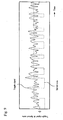
- Fig. 5 is a drawing for explaining a relation of the received signal, the toggle signal, and the spread code.
- the received signal shown in Fig. 5(a) is a carrier (150 MHz ⁇ 15 ppm) modulated by Binary Phase Shift Keying using the spread code on the transmitter end.
- the received signal does not include noise from transmission channel.
- a correlated result having an waveform drawn in a solid line in Fig. 5(b) is obtained by correlating between the received signal shown in Fig. 5(a) and the expected signal.
- the toggle filter 101 outputs the waveform drawn in the solid line as the toggle signal.
- Peaks of the waveform of the toggle signal shown in Fig. 5(b) indicate the position where partial waveforms being most likely to match with waveforms of the expected signal in the received signal exist (in other words, the position that is presumed to be the toggle point).
- the spread code applied for spreading the carrier at the transmitter the waveform drawn in a broken line in Fig. 5(b)
- the toggle signal are overlapped, it is found that the peaks of the toggle signal are matched with the phase-changed point of the spread code.
- the receiver of the equipment in the present embodiment correlates between the received signal and the expected signal after the received signal is entered, then detects the candidates of the toggle point included in the received signal.
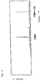
- Fig. 6 is a drawing for showing an example of the waveform of the spread code applied for spreading the carrier and the carrier waveform spreaded by the spread code on the transmitting end, and a drawing of an example of the carrier and the spread code being synchronized.
- Fig. 7 is a drawing for showing an example of the carrier waveform when the carrier and the spread code are not synchronized.
- Fig. 6 (a) shows the spread code.
- Fig 6(b) shows a waveform of the carrier spreaded by the spread code of Fig. 6(a) .
- Fig. 6(c) is an enlarged view of a part of the spread code corresponding to P of the carrier of Fig. 6 (b) (Q in Fig. 6(a)).
- Fig. 6 (d) is an enlarged view of P of the carrier of Fig. 6 (b) .
- a phase of the carrier in P is changed 180 degrees by the spread code shown in Fig. 6 (c) at the point where the carrier is zero.
- the spread code is synchronized when the carrier passes across the zero in this example.
- the carrier shows the waveform including the toggle point as shown in Fig. 7(b) .
- the toggle point is produced without synchronizing the carrier and the spread code.
- the toggle point included in the carrier of the received signal can be detected steadily (detected preliminary), even if the carrier and the spread code for spreading the carrier are not synchronized as shown in Fig. 7 (b) as well as they are synchronized as shown in Fig. 6 (d) .
- the toggle filter 101 makes it possible by complex calculation. In other words, even if the carrier has the frequency deviation; if the phase of the carrier is guaranteed at least an equivalent of one chip-time (or guaranteed half length of the expected signal), the toggle filter 101 can detect, without reference to the waveform of the carrier, the point where the phase is reversed 180 degrees (or the point that is presumed to be the toggle point) in the carrier.
- the toggle point can be detected when the phase of the carrier is guaranteed at least an equivalent of one chip-time. Accordingly, an allowable value about the phase is larger by the ratio of the spread-code length than conventional procedures (slide method and others).
- the spread code the period of which is one second and the code length of which is 1,023 chips
- the phase of the carrier can be allowable up to 180-degree-change in two chip-times (approximately 2 ms). Therefore, when the carrier frequency is 150 MHz, the allowable value is 250 Hz.
- the phase of the carrier can be allowable up to 180-degree-change in 0.2 ms; if the carrier frequency is 150 MHz, the allowable value is 2.50 kHz.
- the deviation can be allowable up to ⁇ 16 ppm; a normal quartz-crystal oscillator can be employed, a very low-priced transmission system can be realized.
- Fig. 8 is a drawing for showing an example of the received signal including noise.
- Fig. 8(a) shows the spread code applied on the transmitting end.
- Fig. 8(b) shows the transmitting signal (150 MHz ⁇ 15 ppm) modulated by Binary Phase Shift Keying using the spread code of the Fig. 8(a).
- Fig 8(c) shows the received signal received on the receiver after transmitted via the transmission channel.
- the received signal of Fig. 8(c) is calculated numerically so that the S/N ratio (the S/N ratio at the stage of limiting the band on the receiver) may be -17.4 dB by adding a lot of noise power on the signal power of the transmitting signal of Fig. 8 (b) .
- Fig. 9 is a drawing for explaining a relation of the toggle signal, outputted from the toggle filter 101 when the received signal of Fig. 8 (c) is inputted into the toggle filter 101, and the spread code applied for spreading the carrier.
- a solid line in Fig. 9 shows the waveform of the toggle signal and a broken line shows the waveform of the spread code.
- the toggle signal outputted from the toggle filter 101 is distorted compared with the toggle signal which does not include noise (refer to Fig. 5(b) ).
- peaks in this toggle signal show the position that is presumed to be the toggle point in the received signal.
- Fig. 10 shows a cross-correlated result (cross-correlated function) of the toggle signal (the signal outputted from the toggle filter 101 after the received signal of Fig. 8(c) is inputted) and the spread code by the cross-correlator 103. Peaks value in the cross-correlation shown in Fig. 10 . are candidates of the shift amount ⁇ ( ⁇ 1, ⁇ 2).
- faulty and improper signals are ultimately eliminated and the synchronization can be established quickly by analyzing the result which is obtained by correlating between the toggle signal and the absolute value of differentiated value of the spread code throughout the sequence of the spread code, after the frequency deviation is overcome and pre-processing for obtaining the toggle signal throughout the sequence of the spread code is correlated quickly for detecting the candidates of the toggle point.
- Fig. 11 is a drawing for showing an example of the demodulated signal (the received signal demodulated by the spread code shifted by providing the shift amount ⁇ ) which is outputted from the demodulator 105 and detected as a spectrum in the carrier inspecting section 106.
- a spectrum of 150 MHz is found in this example as shown in Fig. 11 .
- the present invention can establish the synchronization at a high speed since it can detect steadily the toggle point where the carrier is not synchronized with the spread code by allowing the frequency deviation of the carrier. Accordingly, the present invention can reduce remarkably the transmitting time and the electric power for transmitting. Furthermore, the high-speed establishment for synchronization brings useful effects to various kinds of fields as well as the problem of the privacy function or the effective time of the battery.
- high-speed means "time corresponding to one sequence of the spread code”. Accordingly, the synchronization can be established within the time corresponding to one sequence of the applied spread code from the beginning of the receiving. For example, when the spread code, the one chip-time of which is 0.1 ms and the code length of which is 1,023 chips, is applied; one sequence is 0.1 s.
- eight sequences can be transmitted in 0.8 seconds and eight-bits information can be transmitted.
- the burst transmission transmitted once in ten seconds uses only the one-twelfth of the time, the other time can be used for other communications.
- the spread spectrum communication which normally requires a long time can be achieved by continual communication.
- the present invention can resolve the frequency deviation 0.5 Hz and can detect the radial velocity of 1 m/s from the receiving station. Accordingly, the transmission quality is improved, thus even low quality transmitters on animals (such as birds and humans) or on low-speed movable bodies can communicate.
- the present invention can be applied for detecting the speed of low-speed movable bodies and for estimating locations.
- Fig. 12 is a drawing for showing another example of the demodulated signal which is outputted from the demodulator 105 and detected as a spectrum in the carrier inspecting section 106, and a drawing for showing an example of the result of a mixed numerical calculation of two carriers differed by 10 Hz.
- the carrier frequency is demodulated and detected after the synchronization is established. Accordingly, the present invention can communicate information by different frequencies having the same spread code. More specifically, the frequency deviation (150 MHz ⁇ 15 ppm (2.25 kHz)) of the carrier can be divided by 5 Hz. Thus, the present invention enables multiplex communication.
- the candidate of the toggle point is detected to begin with, then the spread code is applied. Accordingly, more than one spread code can be detected simultaneously.
- the present invention enables transmission of information by more than one spread code and more than one frequency of the carrier. Therefore, the present invention enables multiplex communication by a wider technique, and enables massive communications. Moreover, the present invention can suppress the interference properly.
- the toggle filter 101 is employed for detecting the toggle point as the toggle detecting unit, and the toggle filter 101 detects the phase-change point in the received signal.
- the phase-change point in the received signal may be detected without the toggle filter by Hilbert conversion, by detecting phase, or by PLL (Phase Locked Loop).
- the toggle detecting unit may be configured with a Surface Acoustic Wave (SAW) device filter, a DSP, or other circuits.
- SAW Surface Acoustic Wave
- the present invention can be applied to all the media for transmission such as transmission by electric wave, transmission by acoustic wave, and transmission by light wave. Furthermore, the present invention can be applied to a high-power spread spectrum communication as well as a super-low-power long-distance communication.
- the equipment of this invention for spread spectrum communication enables to establish synchronization of the spread code even if the carrier frequency is not known precisely since it preliminarily detects the candidate of the toggle point in the received signal on the carrier and outputs the toggle signal, then correlates between the outputted toggle signal and the absolute value of differentiated value of the spread code, then calculates the shift amount of the spread code based on the peak value of the cross-correlation, and then demodulates the received signal by multiplying the received signal by the spread code which is shifted according to the calculated shift amount.
- the toggle point can be detected steadily and the high-speed synchronization can be realized even if the toggle point where the carrier is not synchronized with the spread code by allowing the frequency deviation of the carrier.
Landscapes
- Engineering & Computer Science (AREA)
- Computer Networks & Wireless Communication (AREA)
- Signal Processing (AREA)
- Synchronisation In Digital Transmission Systems (AREA)
- Mobile Radio Communication Systems (AREA)
- Cable Transmission Systems, Equalization Of Radio And Reduction Of Echo (AREA)
Applications Claiming Priority (1)
| Application Number | Priority Date | Filing Date | Title |
|---|---|---|---|
| PCT/JP2003/001054 WO2004070967A1 (ja) | 2003-02-03 | 2003-02-03 | スペクトラム拡散方式の通信装置、及び、その高速同期確立法 |
Publications (3)
| Publication Number | Publication Date |
|---|---|
| EP1528690A1 EP1528690A1 (en) | 2005-05-04 |
| EP1528690A4 EP1528690A4 (en) | 2007-06-20 |
| EP1528690B1 true EP1528690B1 (en) | 2008-10-22 |
Family
ID=32843951
Family Applications (1)
| Application Number | Title | Priority Date | Filing Date |
|---|---|---|---|
| EP03815726A Expired - Lifetime EP1528690B1 (en) | 2003-02-03 | 2003-02-03 | Spread spectrum system communication unit and its method for establishing high speed synchronization |
Country Status (7)
| Country | Link |
|---|---|
| US (1) | US7471716B2 (ja) |
| EP (1) | EP1528690B1 (ja) |
| JP (1) | JP3639839B2 (ja) |
| AT (1) | ATE412276T1 (ja) |
| DE (1) | DE60324283D1 (ja) |
| TW (1) | TW200419983A (ja) |
| WO (1) | WO2004070967A1 (ja) |
Families Citing this family (10)
| Publication number | Priority date | Publication date | Assignee | Title |
|---|---|---|---|---|
| JP4428143B2 (ja) * | 2004-05-28 | 2010-03-10 | ソニー株式会社 | 通信装置、通信方法及びプログラム |
| US7698098B2 (en) * | 2008-02-18 | 2010-04-13 | Thermo Electron Scientific Instruments Llc | Efficient spectral matching, particularly for multicomponent spectra |
| JP4635060B2 (ja) * | 2008-02-20 | 2011-02-16 | 株式会社日本自動車部品総合研究所 | スペクトラム拡散通信用の受信装置 |
| JP5188204B2 (ja) * | 2008-02-28 | 2013-04-24 | 三菱電機株式会社 | 測距通信装置 |
| WO2012090266A1 (ja) * | 2010-12-27 | 2012-07-05 | 株式会社数理設計研究所 | シフト法によるデータ通信装置、及び、データ通信方法 |
| US8446931B1 (en) * | 2011-04-19 | 2013-05-21 | L-3 Communications Corp | Chip timing synchronization for link that transitions between clear and spread modes |
| TWI474634B (zh) * | 2011-10-31 | 2015-02-21 | 國立交通大學 | 碼相位擷取裝置及方法 |
| CN103944604B (zh) * | 2014-03-17 | 2016-03-16 | 谷旺 | 伪码捕获装置 |
| JP6471291B2 (ja) * | 2016-01-27 | 2019-02-20 | 群馬県 | 動物用位置情報送信機 |
| CN109451582B (zh) * | 2018-11-12 | 2022-12-06 | 京信网络系统股份有限公司 | 一种信源选择方法、装置、中继设备及存储介质 |
Family Cites Families (7)
| Publication number | Priority date | Publication date | Assignee | Title |
|---|---|---|---|---|
| JP2721474B2 (ja) * | 1992-06-29 | 1998-03-04 | 三菱電機株式会社 | スペクトル拡散通信用受信装置 |
| JP2885052B2 (ja) * | 1994-02-02 | 1999-04-19 | 日本電気株式会社 | 自動周波数制御装置 |
| KR950035142A (ko) * | 1994-03-10 | 1995-12-30 | 가나미야지 준 | 수신장치, 기지국 수신 시스템 및 이동국 수신시스템 |
| US6243409B1 (en) | 1997-07-15 | 2001-06-05 | Novatel, Inc. | Global navigation satellite system receiver with blanked-PRN code correlation |
| JP3407711B2 (ja) * | 2000-04-27 | 2003-05-19 | 日本電気株式会社 | Ds−cdma方式の受信機におけるパスサーチ回路 |
| JP2002335188A (ja) * | 2001-05-08 | 2002-11-22 | Sony Corp | 無線送信装置、無線受信装置、無線送信方法、並びに無線受信方法 |
| US7336693B2 (en) * | 2001-05-08 | 2008-02-26 | Sony Corporation | Communication system using ultra wideband signals |
-
2003
- 2003-02-03 JP JP2004544184A patent/JP3639839B2/ja not_active Expired - Fee Related
- 2003-02-03 WO PCT/JP2003/001054 patent/WO2004070967A1/ja active Application Filing
- 2003-02-03 AT AT03815726T patent/ATE412276T1/de not_active IP Right Cessation
- 2003-02-03 DE DE60324283T patent/DE60324283D1/de not_active Expired - Lifetime
- 2003-02-03 US US10/509,857 patent/US7471716B2/en not_active Expired - Lifetime
- 2003-02-03 EP EP03815726A patent/EP1528690B1/en not_active Expired - Lifetime
- 2003-12-03 TW TW92134078A patent/TW200419983A/zh not_active IP Right Cessation
Also Published As
| Publication number | Publication date |
|---|---|
| TW200419983A (en) | 2004-10-01 |
| US20050180489A1 (en) | 2005-08-18 |
| TWI320642B (ja) | 2010-02-11 |
| US7471716B2 (en) | 2008-12-30 |
| JP3639839B2 (ja) | 2005-04-20 |
| WO2004070967A1 (ja) | 2004-08-19 |
| ATE412276T1 (de) | 2008-11-15 |
| EP1528690A1 (en) | 2005-05-04 |
| JPWO2004070967A1 (ja) | 2006-06-01 |
| DE60324283D1 (de) | 2008-12-04 |
| EP1528690A4 (en) | 2007-06-20 |
Similar Documents
| Publication | Publication Date | Title |
|---|---|---|
| Sozer et al. | Direct sequence spread spectrum based modem for under water acoustic communication and channel measurements | |
| AU764714B2 (en) | Cancellation of pilot and unwanted traffic signals in a CDMA system | |
| CA2125831C (en) | Method of synchronization for code division multiple access radiotelephone communications | |
| EP1434361B1 (en) | Orthogonal code synchronization system and method for spread spectrum CDMA communications | |
| EP0839412B1 (en) | Method and apparatus for spread-spectrum channel estimation | |
| US7224716B2 (en) | Communication methods and apparatus employing spread spectrum techniques and doppler-tolerant polyphase codes | |
| US20090290660A1 (en) | Pseudo Noise Coded Communication Systems | |
| RU96112174A (ru) | Квадратурное мультиплексирование двух сигналов данных, расширенных посредством различных pn-последовательностей | |
| JPH07202756A (ja) | スペクトラム拡散受信機 | |
| KR0159201B1 (ko) | Cdma 시스템에서의 동기식 이중 채널 qpsk 변복조 장치 및 그 변복조방법 | |
| Lohan et al. | Low‐complexity unambiguous acquisition methods for BOC‐modulated CDMA signals | |
| US8300721B2 (en) | Pseudorandom noise code acquisition in direct sequence spread spectrum systems | |
| JP4836158B2 (ja) | 進み/遅れ検出 | |
| EP1528690B1 (en) | Spread spectrum system communication unit and its method for establishing high speed synchronization | |
| WO2000014893A1 (en) | User terminal parallel searcher | |
| KR100390404B1 (ko) | 차동 위상 편이 기반의 분산 표본 포착을 이용한 고속 셀탐색 방법 및 그를 위한 장치 | |
| US20090041096A1 (en) | Efficient synchronization of a spread spectrum signal in the presence of delay and frequency uncertainty | |
| Holden et al. | A spread spectrum based system technique for synchronization of digital mobile communication systems | |
| KR20030020422A (ko) | 지연 록된 루프 내의 변하는 어얼리-레이트 간격 | |
| KR100688329B1 (ko) | 스펙트럼 확산방식의 통신장치, 및, 그 고속동기 확립법 | |
| Glisic et al. | Acquisition of direct-sequence spread-spectrum signals | |
| Lindenmeier et al. | A DSSS-based wireless short range data-link |
Legal Events
| Date | Code | Title | Description |
|---|---|---|---|
| PUAI | Public reference made under article 153(3) epc to a published international application that has entered the european phase |
Free format text: ORIGINAL CODE: 0009012 |
|
| 17P | Request for examination filed |
Effective date: 20041230 |
|
| AK | Designated contracting states |
Kind code of ref document: A1 Designated state(s): AT BE BG CH CY CZ DE DK EE ES FI FR GB GR HU IE IT LI LU MC NL PT SE SI SK TR |
|
| A4 | Supplementary search report drawn up and despatched |
Effective date: 20070523 |
|
| 17Q | First examination report despatched |
Effective date: 20070817 |
|
| GRAP | Despatch of communication of intention to grant a patent |
Free format text: ORIGINAL CODE: EPIDOSNIGR1 |
|
| GRAS | Grant fee paid |
Free format text: ORIGINAL CODE: EPIDOSNIGR3 |
|
| GRAA | (expected) grant |
Free format text: ORIGINAL CODE: 0009210 |
|
| AK | Designated contracting states |
Kind code of ref document: B1 Designated state(s): AT BE BG CH CY CZ DE DK EE ES FI FR GB GR HU IE IT LI LU MC NL PT SE SI SK TR |
|
| REG | Reference to a national code |
Ref country code: GB Ref legal event code: FG4D |
|
| REG | Reference to a national code |
Ref country code: CH Ref legal event code: EP |
|
| REG | Reference to a national code |
Ref country code: IE Ref legal event code: FG4D |
|
| REF | Corresponds to: |
Ref document number: 60324283 Country of ref document: DE Date of ref document: 20081204 Kind code of ref document: P |
|
| NLV1 | Nl: lapsed or annulled due to failure to fulfill the requirements of art. 29p and 29m of the patents act | ||
| PG25 | Lapsed in a contracting state [announced via postgrant information from national office to epo] |
Ref country code: ES Free format text: LAPSE BECAUSE OF FAILURE TO SUBMIT A TRANSLATION OF THE DESCRIPTION OR TO PAY THE FEE WITHIN THE PRESCRIBED TIME-LIMIT Effective date: 20090202 Ref country code: BG Free format text: LAPSE BECAUSE OF FAILURE TO SUBMIT A TRANSLATION OF THE DESCRIPTION OR TO PAY THE FEE WITHIN THE PRESCRIBED TIME-LIMIT Effective date: 20090122 Ref country code: AT Free format text: LAPSE BECAUSE OF FAILURE TO SUBMIT A TRANSLATION OF THE DESCRIPTION OR TO PAY THE FEE WITHIN THE PRESCRIBED TIME-LIMIT Effective date: 20081022 |
|
| PG25 | Lapsed in a contracting state [announced via postgrant information from national office to epo] |
Ref country code: SI Free format text: LAPSE BECAUSE OF FAILURE TO SUBMIT A TRANSLATION OF THE DESCRIPTION OR TO PAY THE FEE WITHIN THE PRESCRIBED TIME-LIMIT Effective date: 20081022 Ref country code: PT Free format text: LAPSE BECAUSE OF FAILURE TO SUBMIT A TRANSLATION OF THE DESCRIPTION OR TO PAY THE FEE WITHIN THE PRESCRIBED TIME-LIMIT Effective date: 20090323 Ref country code: NL Free format text: LAPSE BECAUSE OF FAILURE TO SUBMIT A TRANSLATION OF THE DESCRIPTION OR TO PAY THE FEE WITHIN THE PRESCRIBED TIME-LIMIT Effective date: 20081022 Ref country code: FI Free format text: LAPSE BECAUSE OF FAILURE TO SUBMIT A TRANSLATION OF THE DESCRIPTION OR TO PAY THE FEE WITHIN THE PRESCRIBED TIME-LIMIT Effective date: 20081022 |
|
| PG25 | Lapsed in a contracting state [announced via postgrant information from national office to epo] |
Ref country code: BE Free format text: LAPSE BECAUSE OF FAILURE TO SUBMIT A TRANSLATION OF THE DESCRIPTION OR TO PAY THE FEE WITHIN THE PRESCRIBED TIME-LIMIT Effective date: 20081022 Ref country code: DK Free format text: LAPSE BECAUSE OF FAILURE TO SUBMIT A TRANSLATION OF THE DESCRIPTION OR TO PAY THE FEE WITHIN THE PRESCRIBED TIME-LIMIT Effective date: 20081022 Ref country code: EE Free format text: LAPSE BECAUSE OF FAILURE TO SUBMIT A TRANSLATION OF THE DESCRIPTION OR TO PAY THE FEE WITHIN THE PRESCRIBED TIME-LIMIT Effective date: 20081022 |
|
| PLBE | No opposition filed within time limit |
Free format text: ORIGINAL CODE: 0009261 |
|
| STAA | Information on the status of an ep patent application or granted ep patent |
Free format text: STATUS: NO OPPOSITION FILED WITHIN TIME LIMIT |
|
| PG25 | Lapsed in a contracting state [announced via postgrant information from national office to epo] |
Ref country code: CZ Free format text: LAPSE BECAUSE OF FAILURE TO SUBMIT A TRANSLATION OF THE DESCRIPTION OR TO PAY THE FEE WITHIN THE PRESCRIBED TIME-LIMIT Effective date: 20081022 Ref country code: SE Free format text: LAPSE BECAUSE OF FAILURE TO SUBMIT A TRANSLATION OF THE DESCRIPTION OR TO PAY THE FEE WITHIN THE PRESCRIBED TIME-LIMIT Effective date: 20090122 Ref country code: IT Free format text: LAPSE BECAUSE OF FAILURE TO SUBMIT A TRANSLATION OF THE DESCRIPTION OR TO PAY THE FEE WITHIN THE PRESCRIBED TIME-LIMIT Effective date: 20081022 |
|
| 26N | No opposition filed |
Effective date: 20090723 |
|
| PG25 | Lapsed in a contracting state [announced via postgrant information from national office to epo] |
Ref country code: SK Free format text: LAPSE BECAUSE OF FAILURE TO SUBMIT A TRANSLATION OF THE DESCRIPTION OR TO PAY THE FEE WITHIN THE PRESCRIBED TIME-LIMIT Effective date: 20081022 Ref country code: MC Free format text: LAPSE BECAUSE OF NON-PAYMENT OF DUE FEES Effective date: 20090228 |
|
| REG | Reference to a national code |
Ref country code: CH Ref legal event code: PL |
|
| PG25 | Lapsed in a contracting state [announced via postgrant information from national office to epo] |
Ref country code: LI Free format text: LAPSE BECAUSE OF NON-PAYMENT OF DUE FEES Effective date: 20090228 Ref country code: CH Free format text: LAPSE BECAUSE OF NON-PAYMENT OF DUE FEES Effective date: 20090228 |
|
| PG25 | Lapsed in a contracting state [announced via postgrant information from national office to epo] |
Ref country code: IE Free format text: LAPSE BECAUSE OF NON-PAYMENT OF DUE FEES Effective date: 20090203 |
|
| PG25 | Lapsed in a contracting state [announced via postgrant information from national office to epo] |
Ref country code: GR Free format text: LAPSE BECAUSE OF FAILURE TO SUBMIT A TRANSLATION OF THE DESCRIPTION OR TO PAY THE FEE WITHIN THE PRESCRIBED TIME-LIMIT Effective date: 20090123 |
|
| PG25 | Lapsed in a contracting state [announced via postgrant information from national office to epo] |
Ref country code: LU Free format text: LAPSE BECAUSE OF NON-PAYMENT OF DUE FEES Effective date: 20090203 |
|
| PG25 | Lapsed in a contracting state [announced via postgrant information from national office to epo] |
Ref country code: HU Free format text: LAPSE BECAUSE OF FAILURE TO SUBMIT A TRANSLATION OF THE DESCRIPTION OR TO PAY THE FEE WITHIN THE PRESCRIBED TIME-LIMIT Effective date: 20090423 |
|
| PG25 | Lapsed in a contracting state [announced via postgrant information from national office to epo] |
Ref country code: TR Free format text: LAPSE BECAUSE OF FAILURE TO SUBMIT A TRANSLATION OF THE DESCRIPTION OR TO PAY THE FEE WITHIN THE PRESCRIBED TIME-LIMIT Effective date: 20081022 |
|
| PG25 | Lapsed in a contracting state [announced via postgrant information from national office to epo] |
Ref country code: CY Free format text: LAPSE BECAUSE OF FAILURE TO SUBMIT A TRANSLATION OF THE DESCRIPTION OR TO PAY THE FEE WITHIN THE PRESCRIBED TIME-LIMIT Effective date: 20081022 |
|
| REG | Reference to a national code |
Ref country code: FR Ref legal event code: PLFP Year of fee payment: 14 |
|
| REG | Reference to a national code |
Ref country code: FR Ref legal event code: PLFP Year of fee payment: 15 |
|
| REG | Reference to a national code |
Ref country code: FR Ref legal event code: PLFP Year of fee payment: 16 |
|
| PGFP | Annual fee paid to national office [announced via postgrant information from national office to epo] |
Ref country code: FR Payment date: 20210222 Year of fee payment: 19 |
|
| PGFP | Annual fee paid to national office [announced via postgrant information from national office to epo] |
Ref country code: DE Payment date: 20210225 Year of fee payment: 19 Ref country code: GB Payment date: 20210225 Year of fee payment: 19 |
|
| REG | Reference to a national code |
Ref country code: DE Ref legal event code: R119 Ref document number: 60324283 Country of ref document: DE |
|
| GBPC | Gb: european patent ceased through non-payment of renewal fee |
Effective date: 20220203 |
|
| PG25 | Lapsed in a contracting state [announced via postgrant information from national office to epo] |
Ref country code: FR Free format text: LAPSE BECAUSE OF NON-PAYMENT OF DUE FEES Effective date: 20220228 |
|
| PG25 | Lapsed in a contracting state [announced via postgrant information from national office to epo] |
Ref country code: GB Free format text: LAPSE BECAUSE OF NON-PAYMENT OF DUE FEES Effective date: 20220203 Ref country code: DE Free format text: LAPSE BECAUSE OF NON-PAYMENT OF DUE FEES Effective date: 20220901 |