EP1528633A2 - Structure de boitier en résine pour un dispostif de circuit électrique - Google Patents
Structure de boitier en résine pour un dispostif de circuit électrique Download PDFInfo
- Publication number
- EP1528633A2 EP1528633A2 EP04021956A EP04021956A EP1528633A2 EP 1528633 A2 EP1528633 A2 EP 1528633A2 EP 04021956 A EP04021956 A EP 04021956A EP 04021956 A EP04021956 A EP 04021956A EP 1528633 A2 EP1528633 A2 EP 1528633A2
- Authority
- EP
- European Patent Office
- Prior art keywords
- connector
- resin
- electrical circuit
- circuit device
- case
- Prior art date
- Legal status (The legal status is an assumption and is not a legal conclusion. Google has not performed a legal analysis and makes no representation as to the accuracy of the status listed.)
- Withdrawn
Links
Images


Classifications
-
- H—ELECTRICITY
- H01—ELECTRIC ELEMENTS
- H01R—ELECTRICALLY-CONDUCTIVE CONNECTIONS; STRUCTURAL ASSOCIATIONS OF A PLURALITY OF MUTUALLY-INSULATED ELECTRICAL CONNECTING ELEMENTS; COUPLING DEVICES; CURRENT COLLECTORS
- H01R13/00—Details of coupling devices of the kinds covered by groups H01R12/70 or H01R24/00 - H01R33/00
- H01R13/66—Structural association with built-in electrical component
- H01R13/665—Structural association with built-in electrical component with built-in electronic circuit
- H01R13/6683—Structural association with built-in electrical component with built-in electronic circuit with built-in sensor
-
- G—PHYSICS
- G01—MEASURING; TESTING
- G01P—MEASURING LINEAR OR ANGULAR SPEED, ACCELERATION, DECELERATION, OR SHOCK; INDICATING PRESENCE, ABSENCE, OR DIRECTION, OF MOVEMENT
- G01P1/00—Details of instruments
- G01P1/02—Housings
- G01P1/023—Housings for acceleration measuring devices
-
- H—ELECTRICITY
- H01—ELECTRIC ELEMENTS
- H01R—ELECTRICALLY-CONDUCTIVE CONNECTIONS; STRUCTURAL ASSOCIATIONS OF A PLURALITY OF MUTUALLY-INSULATED ELECTRICAL CONNECTING ELEMENTS; COUPLING DEVICES; CURRENT COLLECTORS
- H01R13/00—Details of coupling devices of the kinds covered by groups H01R12/70 or H01R24/00 - H01R33/00
- H01R13/46—Bases; Cases
- H01R13/502—Bases; Cases composed of different pieces
- H01R13/504—Bases; Cases composed of different pieces different pieces being moulded, cemented, welded, e.g. ultrasonic welding, or swaged together
-
- H—ELECTRICITY
- H01—ELECTRIC ELEMENTS
- H01R—ELECTRICALLY-CONDUCTIVE CONNECTIONS; STRUCTURAL ASSOCIATIONS OF A PLURALITY OF MUTUALLY-INSULATED ELECTRICAL CONNECTING ELEMENTS; COUPLING DEVICES; CURRENT COLLECTORS
- H01R9/00—Structural associations of a plurality of mutually-insulated electrical connecting elements, e.g. terminal strips or terminal blocks; Terminals or binding posts mounted upon a base or in a case; Bases therefor
- H01R9/16—Fastening of connecting parts to base or case; Insulating connecting parts from base or case
-
- B—PERFORMING OPERATIONS; TRANSPORTING
- B60—VEHICLES IN GENERAL
- B60R—VEHICLES, VEHICLE FITTINGS, OR VEHICLE PARTS, NOT OTHERWISE PROVIDED FOR
- B60R21/00—Arrangements or fittings on vehicles for protecting or preventing injuries to occupants or pedestrians in case of accidents or other traffic risks
- B60R21/01—Electrical circuits for triggering passive safety arrangements, e.g. airbags, safety belt tighteners, in case of vehicle accidents or impending vehicle accidents
- B60R2021/01006—Mounting of electrical components in vehicles
-
- H—ELECTRICITY
- H01—ELECTRIC ELEMENTS
- H01R—ELECTRICALLY-CONDUCTIVE CONNECTIONS; STRUCTURAL ASSOCIATIONS OF A PLURALITY OF MUTUALLY-INSULATED ELECTRICAL CONNECTING ELEMENTS; COUPLING DEVICES; CURRENT COLLECTORS
- H01R2201/00—Connectors or connections adapted for particular applications
- H01R2201/26—Connectors or connections adapted for particular applications for vehicles
-
- H—ELECTRICITY
- H01—ELECTRIC ELEMENTS
- H01R—ELECTRICALLY-CONDUCTIVE CONNECTIONS; STRUCTURAL ASSOCIATIONS OF A PLURALITY OF MUTUALLY-INSULATED ELECTRICAL CONNECTING ELEMENTS; COUPLING DEVICES; CURRENT COLLECTORS
- H01R43/00—Apparatus or processes specially adapted for manufacturing, assembling, maintaining, or repairing of line connectors or current collectors or for joining electric conductors
- H01R43/20—Apparatus or processes specially adapted for manufacturing, assembling, maintaining, or repairing of line connectors or current collectors or for joining electric conductors for assembling or disassembling contact members with insulating base, case or sleeve
- H01R43/24—Assembling by moulding on contact members
Definitions
- the present invention relates to a resin housing structure of electrical circuit device mounted in a vehicle.
- the electrical circuit device 101 for detecting collision includes a circuit portion 112 having a G sensor mounted thereon, a connector terminal 113 for electrically connecting the circuit portion 112 to an external device (referred to generally as an "external connection"), and a resin case 110 which is molded integrally with these elements.
- a recess portion 110a is formed at one end side of the resin case 110 so that a portion of the connector terminal 113 is exposed to project into the recess portion 110a.
- a vehicle fixing portion 122 having a thick metal bush embedded therein for fixing to the vehicle is equipped at the other end side.
- the electrical circuit device 101 is fixed to the front portion of the vehicle through the vehicle fixing portion 122.
- a plug at an air bag control device side is engagingly inserted in the recess portion 110a so that the air bag control device and the circuit portion 112 are electrically connected to each other through the connector terminal 113, and a G detection signal detected by the G sensor may be transmitted to the air bag control device.
- the connector shape and vehicle fixing shape of the electrical circuit device mounted in the vehicle are determined on the basis of the design demands of a vehicle maker. Therefore, the determination of a fixing place of the electrical circuit device, etc. changes, and thus resin cases having various shapes may be needed.
- three kinds of connector shapes such as 2P connector, 4P connector and 6P connector are assumed and also three kinds of vehicle fixing shapes such as metal bush thick type, metal bush thin type and metal bolt type are assumed, nine types of case shapes are achieved by multiplying the number (three) of the types in the connector shape and the number (three) of the types in the vehicle fixing shape are needed.
- Fig. 7 shows the nine types in the overall shape of the electrical circuit device.
- (1) to (3) represent metal bush thick types
- (4) to (6) represent metal bush thin types
- (7) to (9) represent metal bolt types
- (1), (4), (7) represent 2P connectors
- (2), (5), (8) represent 4P connectors
- (3), (6), (9) represent 6P connectors.
- Nine kinds of molds for resin molding are needed to mold resin cases of these nine kinds of shapes. As described above, such a requirement to manufacture so many kinds of molding molds to adapt to the various shapes of the electrical circuit device significantly increases the manufacturing cost of the molding molds and is a problem. When a new shape of the electrical circuit device is created, a mold for molding must be manufactured every time the a new shape is added, making it difficult to take a quick countermeasure.
- a resin housing structure of electrical circuit device mounted in a vehicle is characterized in that a resin connector equipped with an electrical circuit having a sensor mounted thereon and a connector terminal for electrically connecting the electrical circuit to the external, and a resin case equipped with a fixing portion to be fixed to a vehicle are divisionally formed, and the resin connector and the resin case are joined to each other and unified into one body.
- the resin connector formed by using a mold for molding the resin connector and the resin case formed by using a mold for molding the resin case are integrally joined to each other, whereby the number of types of molds can be more greatly reduced as compared with a conventional structure achieved by manufacturing a resin housing of overall electrical circuit device with a single molding mold. Accordingly, the cost required for the molding molds can be reduced. Furthermore, when an electrical circuit device having a new shape can be implemented by combining an existing resin connector shape and an existing resin case shape, it can be manufactured by using an existing mold for molding the resin connector and an existing mold for molding the resin case without newly forming a molding mold, so that the present invention can take a quick countermeasure to provide an increase of the types in the shape of the electrical circuit device.
- the shape of the resin connector is selected from plural kinds of connector shapes and the shape of the fixing portion of the resin case is selected from plural kinds of fixing shapes. Therefore, the present invention can adapt to a electrical circuit device whose number of types in shape is equal to the product of the number of types in the connector shape and the number of types in the vehicle fixing shape.
- the resin connector and the resin case are joined to each other by any one of adhesion based on adhesive, laser welding, vibration welding, ultrasonic welding, caulking, DSI formation. Accordingly, in accordance with a specification required to the electrical circuit device, the resin connector and the resin case can be surely integrally joined to each other according to any one joint method.
- the senor is preferably a G sensor for detecting acceleration. Accordingly, in collision detecting electrical circuit device having a G sensor mounted therein, many kinds of connector shapes and fixing shapes can be dealt with by a few types of molding molds.
- the number of molds can be reduced to be less than that of the conventional structure that the resin housing of the overall electrical circuit device is manufactured by a single molding mold. Accordingly, the manufacturing cost of the molding molds can be reduced. Furthermore, when an electrical circuit device having a new shape can be implemented by combining an existing resin connector shape and an existing resin case shape, it can be manufactured by using an existing mold for molding the resin connector and an existing mold for molding the resin case without newly forming a molding mold. Therefore, the present invention can take a quick countermeasure to increase of the number of types concerning the shapes of electrical circuit device.
- the electrical circuit device 1 is a collision detecting sensor which is equipped to the front portion of a vehicle and transmits a G detection signal representing occurrence of collision or vibration to an air bag control device.
- the electrical circuit device 1 is constructed by separately forming a connector portion 10 and a case portion 20 and then joining these portions into one body. The constructions of the connector portion 10 and the case portion 20 and the joining of these portions will be described more fully below.
- the connector portion 10 mainly comprises a connector main body 11 formed of a resin material, a circuit portion 12 having a G sensor mounted thereon, and a connector terminal 13 connected to the circuit portion 12.
- the connector main body 11 is a resin-molded part that may be formed from, for example, PBT (polybuthylene terephthalate) resin, nylon resin or the like.
- the connector main body 11 is equipped with a recess portion 11 a for receiving, for example, a plug of a signal transmitting code electrically connected to the air bag control device.
- the circuit portion 12 comprises a P-plate (glass epoxy type board) on which an electrical circuit is mounted.
- the electrical circuit includes a G sensor and outputs collision or vibration detected by the G sensor as a G detection signal.
- the circuit portion 12 is supported by a wire 14 connected to a connector terminal 13 exposed from the end face of the connector main body 11 at the opposite side to the recess portion 11 a, and electrically connected to the wire 14.
- the circuit portion 12 may be designed in such a P-plate less type that the G sensor is directly mounted on the connector main body 11 without using any P-plate.
- the connector terminal 13 is a pin-type metal part electrically connected to the circuit portion 12 and the wire 14. About half of the connector terminal 13 containing one end portion thereof is exposed to project into the inside of the recess portion 11 a of the connector main body 11, and about the remaining half containing the other end portion is integrally molded with the connector main body 11 to be embedded in the connector main body 11.
- the plug of the signal transmitting code connected to the air bag control device described above is engagingly inserted in the recess portion 11 a, the plug and the exposed portion of the terminal connector 13 are brought into contact with each other, whereby the air bag control device and the circuit portion 12 are electrically connected to each other.
- a 2P type terminal connector in which two end portions of a pin-type terminal connector 13 are exposed in the recess portion 11 a of the connector main body 11 is adopted.
- a 4P type terminal connector in which four end portions are exposed or a 6P type terminal connector in which six end portions are exposed may be adopted.
- the electrical circuit device further includes a case portion 20 mainly comprised of a case main body 21 formed of resin material and a fixing portion 22 to be fixed to the vehicle.
- the case main body is a resin-molded part, and formed of PBT (polybuthylene terephthalate) resin, nylon resin or the like as in the case of the connector main body 11.
- PBT polybuthylene terephthalate
- One end side of the case portion 20 is designed in a tapered shape having a large diameter, and equipped with a recess portion 21 a forming a tapered space for accommodating the circuit portion 12 described above when the connector portion 10 is joined.
- the other end side of the case portion 20 is equipped with a vehicle fixing portion 22 to be fixed to the vehicle.
- a metal bush is embedded in the vehicle fixing portion 22, and the vehicle fixing portion is fixed to the fixing position of the vehicle side through the metal bush by caulking.
- the connector portion 10 and the case portion 20 described above are unified into one body by joining the peripheral edge of the circuit portion 12 of the connector main body 11 and the inner peripheral surface of the recess portion 21 a of the case main body 21 under the state that the circuit portion 12 of the connector portion 10 is accommodated in the recess portion 21 a of the case portion 20.
- the joining method may be selected from various methods in accordance with the requirements defined by the specification of the electrical circuit device. For example, adhesion using adhesive agent, laser welding, vibration welding, ultrasonic welding, caulking, DSI (Die Slide Injection) molding, etc. may be adopted as the joining method.
- the connector portion and the case portion are integrally resin-molded with each other, and thus in order to manufacture nine types in the shape of the electrical circuit device, it is required to prepare nine types of resin molding molds.
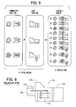
- the present invention can adapt to the nine types in shape of electrical circuit device by using three types of molds for molding the connector portion 10 and three types of molds for molding the case portions 20, totally six types of resin molding molds.
- Fig. 5 is a diagram showing that nine variations of electric circuit equipment can be covered by using six molds.
- the left side of Fig. 5 shows three types in the connector shape of the connector portion
- the center side of Fig. 5 shows three types in vehicle fixing shape of the case portion
- the right side of Fig. 5 shows the overall shape of nine types of electrical circuit device.
- the vehicle fixing shapes in respective electrical circuit device are the metal bush thick type in (1) to (3), the metal bush thin type in (4) to (6) and the metal bolt type in (7) to (9).
- the connector shapes are the 2P connector in (1), (4), (7), the 4P connector in (2), (5), (8) and the 6P connector in (3), (6), (9).
- the electrical circuit device having the shape (1) is manufactured by joining and unifying the connector portion molded with a mold for the 2P connector and a case portion molded with a mold for the metal bush thick type.
- the electrical circuit device having the shape (9) is manufactured by joining and unifying the connector portion molded with a mold for the 6P connector and the case portion molded with a mold for the metal bolt type.
- the connector portion 10 manufactured by using the mold for molding the connector portion 10 and the case portion manufactured by using the mold for molding the case portion 20 are joined and unified into one body, whereby the number of molds can be reduced more greatly as compared with the conventional structure that the resin housing of the overall electrical circuit device is manufactured by one mold. Accordingly, the cost required to manufacture the molds can be reduced. Furthermore, when an electrical circuit device having a new shape can be implemented by combining the shape of an existing connector portion 10 and the shape of an existing case portion 20, the electrical circuit device concerned can be manufactured by using both the existing molds for the connector portion 10 and the case portion 20 without manufacturing any new mold, so that the increase of the types in shape of electrical circuit device can be quickly supported.
- the connector portion 10 is selected from plural types of connector shapes, and also the fixing portion of the case 20 is selected from plural types of fixing shapes. Accordingly, an electrical circuit device whose number of types is equal to the product of the number of types in connector shape and the number of types in fixing shape can be supported.
- the electrical circuit device 1 is collision detecting electric circuit equipment in which a G sensor for detecting acceleration is mounted, and thus collision detecting electrical circuit device in which many types of connector shapes and fixing shapes exist can be supported by a small number of types in shape of molds.
- the connector shapes and vehicle fixing shapes of the electrical circuit device in the above embodiments are merely examples, and thus it should be understood that the present invention is not limited to these examples.
- the resin housing structure of the electrical circuit device of the present invention is applicable to electrical circuit device having various kinds of mechanic or electric sensors for which plural kinds of connector shapes and vehicle fixing shapes exist.
Landscapes
- Engineering & Computer Science (AREA)
- Microelectronics & Electronic Packaging (AREA)
- Physics & Mathematics (AREA)
- General Physics & Mathematics (AREA)
- Details Of Connecting Devices For Male And Female Coupling (AREA)
- Connector Housings Or Holding Contact Members (AREA)
- Coupling Device And Connection With Printed Circuit (AREA)
Applications Claiming Priority (2)
| Application Number | Priority Date | Filing Date | Title |
|---|---|---|---|
| JP2003372946A JP4207753B2 (ja) | 2003-10-31 | 2003-10-31 | 電気回路機器の樹脂筐体構造 |
| JP2003372946 | 2003-10-31 |
Publications (2)
| Publication Number | Publication Date |
|---|---|
| EP1528633A2 true EP1528633A2 (fr) | 2005-05-04 |
| EP1528633A3 EP1528633A3 (fr) | 2006-01-18 |
Family
ID=34420244
Family Applications (1)
| Application Number | Title | Priority Date | Filing Date |
|---|---|---|---|
| EP04021956A Withdrawn EP1528633A3 (fr) | 2003-10-31 | 2004-09-15 | Structure de boitier en résine pour un dispostif de circuit électrique |
Country Status (4)
| Country | Link |
|---|---|
| US (1) | US20050092422A1 (fr) |
| EP (1) | EP1528633A3 (fr) |
| JP (1) | JP4207753B2 (fr) |
| CN (1) | CN1611948B (fr) |
Cited By (2)
| Publication number | Priority date | Publication date | Assignee | Title |
|---|---|---|---|---|
| EP2001092A1 (fr) * | 2008-02-11 | 2008-12-10 | Continental Automotive GmbH | Appareil électrique pour un véhicule automobile, en particulier capteur |
| WO2012089590A1 (fr) * | 2010-12-29 | 2012-07-05 | Robert Bosch Gmbh | Boîtier comprenant un adaptateur de fiche relié à un surmoulage de boîtier par le biais d'une interface standardisée |
Families Citing this family (10)
| Publication number | Priority date | Publication date | Assignee | Title |
|---|---|---|---|---|
| JP4544107B2 (ja) * | 2005-06-29 | 2010-09-15 | 株式会社デンソー | センサ装置 |
| JP2008241456A (ja) | 2007-03-27 | 2008-10-09 | Denso Corp | センサ装置 |
| JP4356768B2 (ja) * | 2007-05-18 | 2009-11-04 | 株式会社デンソー | 電子装置及びその成形金型 |
| JP4906819B2 (ja) * | 2007-12-11 | 2012-03-28 | 三菱電機株式会社 | 圧縮機およびトルク制御装置並びに空気調和機 |
| JP5157967B2 (ja) * | 2009-03-06 | 2013-03-06 | 株式会社デンソー | センサ装置およびその取付構造 |
| JP2014126189A (ja) * | 2012-12-27 | 2014-07-07 | Denso Corp | 車両用電子装置の取付構造及びその取付けに用いられる位置ずれ矯正ワッシャ |
| JP6166654B2 (ja) | 2013-12-26 | 2017-07-19 | 矢崎総業株式会社 | 電子回路ユニットにおける外装ケースの成形方法 |
| DE102014215920A1 (de) * | 2014-08-12 | 2016-02-18 | Continental Automotive Gmbh | Sensorbaugruppe mit einem Schaltungsträger und einer Sensorelektronik sowie Verfahren zu deren Herstellung |
| DE102014219030B4 (de) | 2014-09-22 | 2016-07-07 | Robert Bosch Gmbh | Steckermodul |
| JP2020202010A (ja) * | 2019-06-05 | 2020-12-17 | 株式会社オートネットワーク技術研究所 | コネクタ装置 |
Family Cites Families (11)
| Publication number | Priority date | Publication date | Assignee | Title |
|---|---|---|---|---|
| IT1211176B (it) * | 1987-07-03 | 1989-10-06 | Veglia Borletti Srl | Procedimento di assemblaggio di un dispositivo sensore di temperatura e dispositivo sensore cosi ottenuto |
| US5554806A (en) * | 1994-06-15 | 1996-09-10 | Nippondenso Co., Ltd. | Physical-quantity detecting device |
| US5747694A (en) * | 1995-07-28 | 1998-05-05 | Nippondenso Co., Ltd. | Pressure sensor with barrier in a pressure chamber |
| DE19608675C2 (de) * | 1996-03-06 | 1999-07-29 | Delphi Automotive Systems Gmbh | Temperaturmeßvorrichtung mit einer medienführenden Rohrleitung |
| CN1139989C (zh) * | 1997-10-20 | 2004-02-25 | 株式会社日立制作所 | 半导体模块及使用该半导体模块的电力变换装置 |
| JP2000228856A (ja) * | 1999-02-05 | 2000-08-15 | Mitsubishi Electric Corp | ステッピングモータ |
| DE19910284A1 (de) * | 1999-03-09 | 2000-09-28 | Mannesmann Vdo Ag | Sensor zur kombinierten Temperatur- und Füllstandserfassung |
| DE10000350A1 (de) * | 2000-01-07 | 2001-07-12 | Kostal Leopold Gmbh & Co Kg | Sensormodul für ein elektrisches Steckergehäuse |
| JP2002372473A (ja) * | 2001-04-12 | 2002-12-26 | Fuji Electric Co Ltd | 半導体センサ収納容器およびその製造方法、並びに半導体センサ装置 |
| DE10141218B4 (de) * | 2001-08-23 | 2021-04-29 | HELLA GmbH & Co. KGaA | Verfahren zur Herstellung einer Verbindungsanordnung sowie nach diesem Verfahren hergestellte Verbindungsanordnung |
| JP4357789B2 (ja) * | 2002-03-26 | 2009-11-04 | 本田技研工業株式会社 | 自動二輪車 |
-
2003
- 2003-10-31 JP JP2003372946A patent/JP4207753B2/ja not_active Expired - Fee Related
-
2004
- 2004-09-15 EP EP04021956A patent/EP1528633A3/fr not_active Withdrawn
- 2004-09-28 US US10/950,461 patent/US20050092422A1/en not_active Abandoned
- 2004-10-29 CN CN200410088036.6A patent/CN1611948B/zh not_active Expired - Fee Related
Cited By (2)
| Publication number | Priority date | Publication date | Assignee | Title |
|---|---|---|---|---|
| EP2001092A1 (fr) * | 2008-02-11 | 2008-12-10 | Continental Automotive GmbH | Appareil électrique pour un véhicule automobile, en particulier capteur |
| WO2012089590A1 (fr) * | 2010-12-29 | 2012-07-05 | Robert Bosch Gmbh | Boîtier comprenant un adaptateur de fiche relié à un surmoulage de boîtier par le biais d'une interface standardisée |
Also Published As
| Publication number | Publication date |
|---|---|
| EP1528633A3 (fr) | 2006-01-18 |
| CN1611948A (zh) | 2005-05-04 |
| JP2005135850A (ja) | 2005-05-26 |
| CN1611948B (zh) | 2011-01-19 |
| US20050092422A1 (en) | 2005-05-05 |
| JP4207753B2 (ja) | 2009-01-14 |
Similar Documents
| Publication | Publication Date | Title |
|---|---|---|
| US6389903B1 (en) | Pressure-detecting device coupling member with interchangeable connector part | |
| EP1528633A2 (fr) | Structure de boitier en résine pour un dispostif de circuit électrique | |
| US9482557B2 (en) | Sensor unit for sensing an angular position of a rotating element with respect to a fixed element and bearing assembly comprising such a sensor unit | |
| US20090056446A1 (en) | Multiple-axis sensor package and method of assembly | |
| JP2001165702A (ja) | 磁気変量検出センサ | |
| CN102803025A (zh) | 一种改进的电子装置 | |
| US10451677B2 (en) | Battery state sensing device and manufacturing method therefor | |
| US10670484B2 (en) | Pressure sensor unit including snap fit circular seal | |
| WO2014103469A1 (fr) | Capteur de vitesse de roue et procédé de fabrication de capteur de vitesse de roue | |
| EP0919438A2 (fr) | Réseau de câbles et méthode de cablage pour motocycles | |
| JP4179083B2 (ja) | 回転検出装置 | |
| CN103201150B (zh) | 用于车辆的控制器以及制造用于车辆的控制器的方法 | |
| CN218782884U (zh) | 用于电子膨胀阀的线圈结构、电子膨胀阀和机动车 | |
| CN214067190U (zh) | 轮速传感器芯片模组和轮速传感器 | |
| WO2015096018A1 (fr) | Capteur de vitesse modulaire | |
| US7776247B2 (en) | Method of manufacturing electronic device having resin-molded case and molding tool for forming resin-molded case | |
| CN120641724A (zh) | 用于车辆的传感器组件 | |
| US20110233907A1 (en) | Housing for an electrical circuit | |
| US12571663B2 (en) | Sensor unit and method for producing a sensor unit | |
| CN217276240U (zh) | 一种汽车用传感器护套 | |
| JP4221578B2 (ja) | 磁気検出装置 | |
| KR20190048760A (ko) | 차량용 마그네틱 센서 및 그 제조방법 | |
| CN219997300U (zh) | 超声传感器及车辆 | |
| JP2017077150A (ja) | 電動機およびこれを備える車載用装置、並びに、検査装置および電力入力部検査方法 | |
| US6574119B2 (en) | Electronic device |
Legal Events
| Date | Code | Title | Description |
|---|---|---|---|
| PUAI | Public reference made under article 153(3) epc to a published international application that has entered the european phase |
Free format text: ORIGINAL CODE: 0009012 |
|
| AK | Designated contracting states |
Kind code of ref document: A2 Designated state(s): AT BE BG CH CY CZ DE DK EE ES FI FR GB GR HU IE IT LI LU MC NL PL PT RO SE SI SK TR |
|
| AX | Request for extension of the european patent |
Extension state: AL HR LT LV MK |
|
| PUAL | Search report despatched |
Free format text: ORIGINAL CODE: 0009013 |
|
| AK | Designated contracting states |
Kind code of ref document: A3 Designated state(s): AT BE BG CH CY CZ DE DK EE ES FI FR GB GR HU IE IT LI LU MC NL PL PT RO SE SI SK TR |
|
| AX | Request for extension of the european patent |
Extension state: AL HR LT LV MK |
|
| RIC1 | Information provided on ipc code assigned before grant |
Ipc: H01R 13/66 20060101ALI20051130BHEP Ipc: H01R 9/16 20060101ALI20051130BHEP Ipc: H01R 13/504 20060101AFI20050216BHEP |
|
| 17P | Request for examination filed |
Effective date: 20060714 |
|
| AKX | Designation fees paid |
Designated state(s): DE FR GB |
|
| 17Q | First examination report despatched |
Effective date: 20080220 |
|
| STAA | Information on the status of an ep patent application or granted ep patent |
Free format text: STATUS: THE APPLICATION IS DEEMED TO BE WITHDRAWN |
|
| 18D | Application deemed to be withdrawn |
Effective date: 20080702 |