EP1528552B1 - Fördervorrichtung für optische Platten und Plattenwiedergabevorrichtung - Google Patents
Fördervorrichtung für optische Platten und Plattenwiedergabevorrichtung Download PDFInfo
- Publication number
- EP1528552B1 EP1528552B1 EP04025529A EP04025529A EP1528552B1 EP 1528552 B1 EP1528552 B1 EP 1528552B1 EP 04025529 A EP04025529 A EP 04025529A EP 04025529 A EP04025529 A EP 04025529A EP 1528552 B1 EP1528552 B1 EP 1528552B1
- Authority
- EP
- European Patent Office
- Prior art keywords
- disk
- ridge
- optical disk
- feeding roller
- conveying device
- Prior art date
- Legal status (The legal status is an assumption and is not a legal conclusion. Google has not performed a legal analysis and makes no representation as to the accuracy of the status listed.)
- Expired - Lifetime
Links
- 230000003287 optical effect Effects 0.000 title claims description 42
- 238000003780 insertion Methods 0.000 claims description 14
- 230000037431 insertion Effects 0.000 claims description 14
- 239000000725 suspension Substances 0.000 description 10
- 230000009471 action Effects 0.000 description 7
- 230000007246 mechanism Effects 0.000 description 7
- 239000002184 metal Substances 0.000 description 6
- 238000013459 approach Methods 0.000 description 4
- 239000000463 material Substances 0.000 description 4
- 241000217377 Amblema plicata Species 0.000 description 2
- 239000011248 coating agent Substances 0.000 description 2
- 238000000576 coating method Methods 0.000 description 2
- 230000008901 benefit Effects 0.000 description 1
- 230000000694 effects Effects 0.000 description 1
- 230000008030 elimination Effects 0.000 description 1
- 238000003379 elimination reaction Methods 0.000 description 1
- 238000012986 modification Methods 0.000 description 1
- 230000004048 modification Effects 0.000 description 1
- 238000012827 research and development Methods 0.000 description 1
- 230000004044 response Effects 0.000 description 1
Images


Classifications
-
- G—PHYSICS
- G11—INFORMATION STORAGE
- G11B—INFORMATION STORAGE BASED ON RELATIVE MOVEMENT BETWEEN RECORD CARRIER AND TRANSDUCER
- G11B17/00—Guiding record carriers not specifically of filamentary or web form, or of supports therefor
- G11B17/02—Details
- G11B17/04—Feeding or guiding single record carrier to or from transducer unit
- G11B17/0401—Details
- G11B17/0402—Servo control
- G11B17/0404—Servo control with parallel drive rollers
-
- G—PHYSICS
- G11—INFORMATION STORAGE
- G11B—INFORMATION STORAGE BASED ON RELATIVE MOVEMENT BETWEEN RECORD CARRIER AND TRANSDUCER
- G11B17/00—Guiding record carriers not specifically of filamentary or web form, or of supports therefor
- G11B17/02—Details
- G11B17/04—Feeding or guiding single record carrier to or from transducer unit
- G11B17/05—Feeding or guiding single record carrier to or from transducer unit specially adapted for discs not contained within cartridges
- G11B17/051—Direct insertion, i.e. without external loading means
Definitions
- the present invention relates to an optical disk conveying device for holding and conveying an optical disk with the help of a rotatable feed roller and an optical disk reproducing device having this optical disk conveying device.
- Figs. 1 show the structure of a disk conveying device for a conventional optical disk reproducing device for automobiles
- Fig. 1A is a front sectional view
- Fig. 1B is a top plan view
- Fig. 1C is a side sectional view.
- a disk conveying device 11 is disposed in front of a lower chassis 10 constituting the main chassis of the device.
- the disk conveying device 11 includes a metal feeding plate 12 extending in the width direction of the lower chassis 10, and a rotary supporting shaft 13 fitted at the center of both sides of the feeding plate 12 and protruding outward is supported slidably in a circular direction by the lower chassis 10.
- a rubber feeding roller 14 of an expanded diameter from the central part towards both ends are rotatably supported through a shaft by the lower chassis.
- the feeding plate 12 is forced to rotate clockwise by the action of a twist coil spring 15 provided around its rotary supporting shaft 13, approaches, in the normal state, a disk guide 31 forming an integral part of the upper chassis 30, and conveys a disk D inserted from an opening for disk insertion 10a by holding the same between the feeding roller 14 and the disk guide 31.
- the opening for disk insertion 10a is formed on the front plate of the lower chassis 10.
- the disk guide 31 consists of a first ridge 31a, a second ridge 31b parallel to the former and disposed at positions facing each other on both sides of the feeding roller 14, and a third ridge 31c formed at a position close to the opening for disk insertion 10a and dogleg-shaped by slanting the central part forward and the both ends backward.
- the ridges 31a, 31b and 31c protrude in the dogleg shape towards the feeding roller 14 and formed in a tapered shape with the same incline so that they may approach the feeding roller 14 from the central part to the both ends.
- the disk D inserted from the opening for disk insertion 10a is conveyed deep into the device by the feeding roller 14 being centered by the respective ridges 31c, 31b and 31a. And at the end of conveyance, the disk D is located at the central position of the turntable that rotates the same.
- the back-end edge of the disk D being pushed by the feeding roller 14, line-contacts the second ridge 31b within a specified range W from a central line CL (for example within a range of 27.1 mm to 37.0 mm for the central line CL) because the angle of inclination ⁇ cannot be made sharper due to the same inclination ⁇ that continues from the both ends to the central line (CL) on the second ridge 31b (ditto in the case of the first ridge 31a and the third ridge 31c).
- Such scratches are particularly problematic because of the likelihood of causing reproduction failures when the disk D is a DVD on which data is recorded on both sides. Even if the disk D is a CD or other similar media on which data is recorded only on one side, a similar problem occurs when the user commits mistakes in inserting the disk such as inserting the disk D upside down.
- the present invention is made in order to solve such prior problems, and its object is to provide an optical disk conveying device capable of conveying without damaging the disk even when the device is made thinner and an optical disk reproducing device having the same.
- the optical disk conveying device of the present invention is an optical disk conveying device for holding and conveying an optical disk between a rotatable feeding roller and disk guides approximately opposite to the feeding roller, wherein the disk guides are disposed at positions approximately in parallel with and opposite to the feeding roller, have a first ridge and a second ridge protruding towards the feeding roller, formed in a tapered shape approaching the feeding roller from a central part towards both ends, and a straight part of which a height of the ridges is approximately constant is formed in the central part of the second ridge disposed on a side of an opening for disk insertion of the ridges, and a first tapered part provided in a connected row arrangement with the straight part and having a specified gradient within a specified range towards the both sides.
- the back-end circumferential periphery of the disk comes off the first ridge, and the user tries to hold and draw out the disk, the back-end part of the disk is located at the low straight part of the second ridge and only the back-end circumferential periphery of the disk point-contacts the first tapered part having a relatively sharp gradient of the second ridge. Therefore, the disk does not line-contact the second ridge even when the disk is drawn out, and it will be possible to prevent the disk from being damaged thereby.
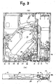
- Fig. 3A is a schematic top plan view showing the lower chassis and suspension chassis assembly in operation of the optical disk reproducing device for automobiles according to the embodiment of the present invention and Fig. 3B is a schematic side view of the lower chassis assembly.
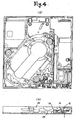
- Fig. 4A is a schematic top plan view illustrating the feeding roller of the device in a position separate from the disk, and Fig. 4B is a schematic side view of the same.
- a disk conveying device 11 is disposed in front of the lower chassis 10.
- the disk conveying device 11 includes a metal feeding plate 12, and a rotary supporting shaft 13 provided at the center of both sides of the feeding plate 12 and protruding outward is supported movably in a circular direction by the lower chassis 10.
- a rubber feeding roller 14 of an expanded diameter from the central part towards both ends are rotatably supported through a shaft by the lower chassis.
- the feeding plate 12 is forced to rotate clockwise by the action of two helical extension springs 1 provided on both sides.
- each of the helical extension springs 1 is supported by a locking piece 2 provided at the back of the front end of the feeding plate and the other end is supported by a locking piece 3 provided on the bottom of the lower chassis 10 so that the load may pass near the lower part of the rotary shaft 13 of the feeding plate 12.
- the suspension chassis 20 is supported by the lower chassis 10 through three dumper mechanisms 21, 22, and 23 each made up of an oil dumper and a coil spring.
- a turntable mechanism and an optical pickup mechanism are fitted on the opening 24 of the suspension chassis 20, and a clamp arm of a disk clamp mechanism for pushing the disk towards the turntable is rotatably fixed through a suspension lock mechanism 25 provided on the inside surface of one side.
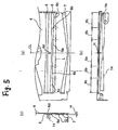
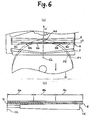
- Fig. 5A is a fragmentary top plan view of the upper chassis of the optical disk reproducing device according to an embodiment of the present invention
- Fig. 5B is a front view thereof
- Fig. 5C is a sectional view as seen from the left side representing a view obtained by turning Figs. 3 by 90°.
- the first ridge 5 and the second ridge 6 among these three ridges are arranged in parallel at positions facing each other on both sides of the feeding roller 14, and the third ridge 7 is formed in the dogleg shape with the both ends slanting backward from the central part located forward at a position near the opening for insertion of the disk 4a formed on the front part of the upper chassis 4 (corresponding to the opening for insertion of the disk 10a in Figs. 3 ).
- the second ridge 6 on the opening for insertion of the disk side among the two parallel ridges 5, 6 is made up of a straight part 6a having a slightly protruding height in the chevron shape at the central part towards the feeding roller 14 and yet having a constant height and width, the first tapered part 6b respectively continuing to protrude in the chevron shape towards the feeding roller 14 on both sides of the straight part 6a so that it may approach the feeding roller 14 from the central part towards both sides, and the second tapered part 6c inclining further on both sides so that the ridge may approach the feeding roller 14.
- the height H of the second ridge 6 from the surface of the upper chassis 4 is about 0.35 mm, and the range L of the straight part 6a is respectively 21.2 mm on one side of the central line CL and 42.4 mm on both sides.
- the width of the first tapered part 6b is approximately 17.5 mm, and its gradient is about 3.2.
- the gradient of the second tapered part 6c is approximately 1.4 similarly to that of the first ridge 5.
- the height H of the first ridge 5 and the third ridge 7 on the central line CL is about 0.35 mm similarly to the height of the straight part 6a of the second ridge 6, and the respective tapered part is inclined at approximately 1.4.
- the first ridge 5 and the second ridge 6 are linked by a bridge 6d on the central line CL.
- a suspension lock mechanism 25 operates at the back edge of the disk, and a suspension lock component 26 provided on one side of the suspension chassis 20 slides forward and its rack 27 engages with a pinion 28.
- the disk conveying motor rotates in the reverse direction, and a reverse operation to the above takes place.
- the clamp arm rises and the disk clamp separates itself from disk
- the pinion 28 slides the rack 27 and the suspension lock component 26 backward
- the feeding plate 12 rises by the action of the cam surface 29, and the feeding plate 12 rises causing the feeding roller 14 to come into contact with the disk and ejects the disk to a position whereat the disk can be grasped from the outside.
- a helical extension spring 1 for forcing to rotate the feeding plate 12 is supported by a locking piece 2 provided at the front edge side of the feeding plate 12 and the other end is supported by a locking piece 3 provided on the bottom surface of the lower chassis 10 so that the load may pass near the lower part of the rotary supporting shaft 13 of the feeding plate 12. Therefore, when the feeding plate 12 is moved circularly in the direction of separating itself from the disk guide, it can be moved circularly with a little force, and a motor of a small output can be used.
- the back edge of the disk D is positioned at the straight part 6a without gradient in the central part of the second ridge 6 and the back-end circumferential periphery of the disk D is in contact with the bridge 6d and is separated from the straight part 6a. Therefore, even if the disk D is drawn out forward, it is possible to prevent any damage to the back-end edge of the disk D.
- the second ridge 6 disposed on the side of the opening for disk insertion 4a among the ridges 5, 6, 7 serving as the disk guides integrally formed with the rotatable feeding roller 14 and the upper chassis 4 is made up of a straight part 6a for the prescribed length L in the central part, the first tapered part 6b having a relatively important gradient gradually approaching the feeding roller 14 for the specified range W on both sides thereto and the second tapered part 6c having a reduced gradient on both sides further thereto, when the feeding roller 14 finishes ejecting the disk D and the user tries to grab and draw out the disk D, at the position P1 of the disk D, the back-end circumferential periphery of the disk D point-contacts the first tapered part 6b having a relatively important gradient of the second ridge 2, it is possible to prevent any possible damages to the back edge of the disk D.
- the back-end circumferential periphery of the disk D is located at the straight part 6a having a low height H and is in point contact with the bridge 6d. Therefore, even if the disk is drawn out, the disk is not damaged.
- the straight part 6a is formed in the form of a rib with a low-height chevron and is connected with the bridge 6d, it is possible to maintain its strength when a thin sheet metal is used for the upper chassis 4.
- the ridges 5, 6, 7 in the present embodiment are formed in the shape of a chevron, their shape is not limited to chevron, and may be triangular or semi-circular. And as long as it is possible to maintain the strength of the disk guide by other means, the straight part 6a of the first ridge 5 may be a flat part with no protrusion. In this case, the elimination of protrusion can secure even more space, and such space may be more effectively used.
- the present invention is applied to the second ridge 6 among the two ridges 5, 6 on both sides of the feeding roller.
- the present invention may be applied to that ridge.
- disk guide is formed integrally with the upper chassis in the present embodiment, it is possible to use disk guides separate from the upper chassis. For example, when a material of a small coefficient of friction is used to form disk guides, it will be unnecessary to coat the same with a coating material.
- the optical disk conveying device includes the second ridge disposed on the side of the opening for disk insertion for the disk guide having a straight part without inclination within a prescribed range in the central part and a tapered part more sharply inclined on both sides thereof. Accordingly, when the disk is drawn out for ejecting, only the back-end circumferential periphery of the disk point-contacts the sharply inclined tapered part, and thus it is possible to prevent damage due to line contact between the disk and the ridge. For this reason, it is useful as an optical disk conveying device for holding and conveying an optical disk between the rotatable feeding roller and the disk guides and as an optical disk reproducing device.
- the present invention is characterized in that the second ridge serving as a disk guide and disposed on the side of the opening for disk insertion is made up of a straight part without inclination within a specified range in the central part and tapered parts within a specified range on both sides thereof with a relatively important inclination, and that when the disk is drawn out for ejecting the disk, only the back-end circumferential periphery of the disk point-contacts the tapered parts having a relatively important inclination.
- Such a structure enables to prevent any damage from occurring due to the line contact between the disk and the ridges and to realize a high-performance and thin optical disk reproducing device.
Landscapes
- Feeding And Guiding Record Carriers (AREA)
Claims (5)
- Transportvorrichtung (11) für optische Speicherplatten zum Halten und Transportieren einer optischen Speicherplatte zwischen einer drehbaren Einziehwalze (14) und einer Speicherplattenführung (4), die an einer Position ungefähr parallel zu der Einziehwalze (14) und dieser gegenüberliegend angeordnet ist,
wobei die Speicherplattenführung (4) einen ersten Wulst (5) und einen zwischen dem ersten Wulst (5) und einer Öffnung zum Einführen einer Speicherplatte angeordneten zweiten Wulst (6) aufweist und beide Wulste (5, 6) in Richtung der Einziehwalze (14) hervorstehen und in sich verjüngender Gestalt ausgebildet sind, die von einem mittleren Teil zu beiden Seiten hin zunimmt,
dadurch gekennzeichnet, dass:der zweite Wulst (6) Folgendes aufweist:einen geraden Teil (6a), der mit ungefähr konstanter Höhe in Richtung der Einziehwalze (14) hervorsteht und in dem mittleren Teil des zweiten Wulstes (6) ausgebildet ist,zwei erste sich verjüngende Teile (6b), die neben dem geraden Teil (6a) vorgesehen sind, undzwei zweite sich verjüngende Teile (6c), die auf beiden Seiten des ersten sich verjüngenden Teils (6b) vorgesehen sind,wobei die zweiten sich verjüngenden Teile (6c) einen flacheren Gradienten aufweisen als der erste sich verjüngende Teil (6b) unddie zweiten sich verjüngenden Teile (6c) und der erste Wulst (5) einen ungefähr ähnlichen Gradienten aufweisen. - Transportvorrichtung für optische Speicherplatten nach Anspruch 1, wobei der erste Wulst und der zweite Wulst über eine Brücke an den mittleren Teilen des ersten Wulsts und des zweiten Wulsts in ungefähr gleicher Höhe miteinander verbunden sind.
- Transportvorrichtung für optische Speicherplatten nach Anspruch 1, wobei der gerade Teil des zweiten Wulsts in einen flachen Teil ohne Vorsprung ausgebildet ist.
- Transportvorrichtung für optische Speicherplatten nach Anspruch 1, wobei die Speicherplattenführungen einstückig mit einem oberen Rahmen der Wiedergabevorrichtung für optische Speicherplatten ausgebildet sind.
- Wiedergabevorrichtung für optische Speicherplatten mit der Transportvorrichtung für optische Speicherplatten nach einem der Ansprüche 1 bis 4.
Applications Claiming Priority (2)
| Application Number | Priority Date | Filing Date | Title |
|---|---|---|---|
| JP2003367650A JP4156490B2 (ja) | 2003-10-28 | 2003-10-28 | 光ディスク搬送装置および光ディスク再生装置 |
| JP2003367650 | 2003-10-28 |
Publications (3)
| Publication Number | Publication Date |
|---|---|
| EP1528552A2 EP1528552A2 (de) | 2005-05-04 |
| EP1528552A3 EP1528552A3 (de) | 2007-12-19 |
| EP1528552B1 true EP1528552B1 (de) | 2011-08-03 |
Family
ID=34420134
Family Applications (1)
| Application Number | Title | Priority Date | Filing Date |
|---|---|---|---|
| EP04025529A Expired - Lifetime EP1528552B1 (de) | 2003-10-28 | 2004-10-27 | Fördervorrichtung für optische Platten und Plattenwiedergabevorrichtung |
Country Status (4)
| Country | Link |
|---|---|
| US (1) | US7401342B2 (de) |
| EP (1) | EP1528552B1 (de) |
| JP (1) | JP4156490B2 (de) |
| CN (1) | CN100463065C (de) |
Families Citing this family (12)
| Publication number | Priority date | Publication date | Assignee | Title |
|---|---|---|---|---|
| WO2007108255A1 (ja) | 2006-03-15 | 2007-09-27 | Clarion Co., Ltd. | ディスクプレーヤ |
| CN101405803A (zh) * | 2006-03-16 | 2009-04-08 | 歌乐株式会社 | 碟片播放器 |
| JP4841405B2 (ja) * | 2006-11-21 | 2011-12-21 | アルパイン株式会社 | ディスク装置 |
| JP2008140428A (ja) * | 2006-11-30 | 2008-06-19 | Tanashin Denki Co | ディスク搬送装置のディスクガイド |
| CN101477815B (zh) * | 2008-01-04 | 2010-08-11 | 谷林电器(深圳)有限公司 | 光盘运送装置 |
| JP2009283029A (ja) * | 2008-05-19 | 2009-12-03 | Panasonic Corp | ディスクドライブ装置 |
| JP5163403B2 (ja) * | 2008-09-30 | 2013-03-13 | 株式会社Jvcケンウッド | ディスク装置のディスク搬送機構およびそれを有するディスク再生装置 |
| JP2011060343A (ja) * | 2009-09-07 | 2011-03-24 | Sony Corp | ディスクドライブ装置及び電子機器 |
| JP5991694B2 (ja) * | 2013-07-17 | 2016-09-14 | 株式会社ソニー・インタラクティブエンタテインメント | 光ディスクドライブ |
| JP6071067B2 (ja) * | 2013-10-01 | 2017-02-01 | 株式会社ニフコ | 支持装置 |
| KR101794875B1 (ko) * | 2015-01-30 | 2017-11-07 | 가부시키가이샤 하리즈 | 투명판 검사 장치 및 투명판 청소 검사 시스템 |
| US11978480B2 (en) * | 2020-03-30 | 2024-05-07 | Sony Interactive Entertainment Inc. | Optical disc drive and electronic equipment |
Family Cites Families (12)
| Publication number | Priority date | Publication date | Assignee | Title |
|---|---|---|---|---|
| US5022023A (en) * | 1987-06-23 | 1991-06-04 | Sony Corporation | Disc drive arrangement for CD player and the like capable of loading different size discs |
| DE4326386A1 (de) * | 1992-08-10 | 1994-02-17 | Samsung Electronics Co Ltd | Diskabspielgerät-Mechanik |
| JP3402408B2 (ja) * | 1994-11-02 | 2003-05-06 | アルパイン株式会社 | ディスクプレーヤのディスク搬送装置 |
| JP3834978B2 (ja) * | 1997-12-22 | 2006-10-18 | ソニー株式会社 | 記録媒体駆動装置 |
| WO1999067783A1 (en) * | 1998-06-22 | 1999-12-29 | Mitsubishi Denki Kabushiki Kaisha | Disk unit |
| JP3739210B2 (ja) | 1998-08-06 | 2006-01-25 | アルパイン株式会社 | ディスク搬送装置 |
| JP2000228044A (ja) * | 1999-02-05 | 2000-08-15 | Kenwood Corp | ディスク装置のディスクローディング機構 |
| US6542453B1 (en) * | 1999-10-08 | 2003-04-01 | Pioneer Corporation | Recording medium read device |
| JP2003059151A (ja) | 2001-08-09 | 2003-02-28 | Matsushita Electric Ind Co Ltd | 光ディスク再生装置 |
| JP2003077198A (ja) | 2001-09-04 | 2003-03-14 | Tanashin Denki Co | ディスク再生機のディスク搬送装置 |
| US6735131B2 (en) * | 2002-01-07 | 2004-05-11 | Intel Corporation | Weak current generation |
| TWI271705B (en) * | 2004-09-14 | 2007-01-21 | Lite On It Corp | Roller structure used in a slot-loading disk drive |
-
2003
- 2003-10-28 JP JP2003367650A patent/JP4156490B2/ja not_active Expired - Fee Related
-
2004
- 2004-10-27 US US10/974,204 patent/US7401342B2/en not_active Expired - Lifetime
- 2004-10-27 EP EP04025529A patent/EP1528552B1/de not_active Expired - Lifetime
- 2004-10-28 CN CNB2004100104384A patent/CN100463065C/zh not_active Expired - Fee Related
Also Published As
| Publication number | Publication date |
|---|---|
| US7401342B2 (en) | 2008-07-15 |
| JP2005135457A (ja) | 2005-05-26 |
| EP1528552A3 (de) | 2007-12-19 |
| CN100463065C (zh) | 2009-02-18 |
| JP4156490B2 (ja) | 2008-09-24 |
| US20050091676A1 (en) | 2005-04-28 |
| CN1637900A (zh) | 2005-07-13 |
| EP1528552A2 (de) | 2005-05-04 |
Similar Documents
| Publication | Publication Date | Title |
|---|---|---|
| US7010798B2 (en) | Disk drive | |
| EP1528552B1 (de) | Fördervorrichtung für optische Platten und Plattenwiedergabevorrichtung | |
| EP1978518A2 (de) | Plattentransporteinheit und Apparatus zur Verarbeitung von Platten | |
| US6751180B2 (en) | Disk player | |
| EP1002315B1 (de) | Plattenladevorrichtung für ein plattengerät | |
| CN100403431C (zh) | 光盘装置 | |
| KR100417106B1 (ko) | 기록매체 장착장치 | |
| JP4136989B2 (ja) | ディスク装置 | |
| KR100417105B1 (ko) | 기록매체 장착장치 | |
| CN100397520C (zh) | 进给辊、光盘传送单元以及光盘记录/重放设备 | |
| JP2003059151A (ja) | 光ディスク再生装置 | |
| KR100417103B1 (ko) | 기록매체 장착장치 | |
| EP1087389A1 (de) | Platteneinheit | |
| WO2003067592A1 (en) | Adapter for non-circular disc | |
| JP3959312B2 (ja) | ディスクドライブ装置のローディング機構 | |
| JP2005116029A (ja) | ディスクプレーヤのディスク搬送機構 | |
| CN101221790B (zh) | 光盘装置 | |
| CN100466083C (zh) | 盘片驱动装置 | |
| JP4184285B2 (ja) | ディスク装置 | |
| JP6472310B2 (ja) | ディスク装置 | |
| JP2006059484A (ja) | 光ディスク装置 | |
| JP4084211B2 (ja) | ディスクプレーヤのディスク搬送機構 | |
| US20090133046A1 (en) | Disc Guiding Apparatus having a Logic Apparatus | |
| US20050060726A1 (en) | Disk drive | |
| WO2006016656A1 (ja) | ディスクドライブ装置 |
Legal Events
| Date | Code | Title | Description |
|---|---|---|---|
| PUAI | Public reference made under article 153(3) epc to a published international application that has entered the european phase |
Free format text: ORIGINAL CODE: 0009012 |
|
| AK | Designated contracting states |
Kind code of ref document: A2 Designated state(s): AT BE BG CH CY CZ DE DK EE ES FI FR GB GR HU IE IT LI LU MC NL PL PT RO SE SI SK TR |
|
| AX | Request for extension of the european patent |
Extension state: AL HR LT LV MK |
|
| RIN1 | Information on inventor provided before grant (corrected) |
Inventor name: KASAMA, HIROSHI Inventor name: KIDO, YOUHIDE |
|
| PUAL | Search report despatched |
Free format text: ORIGINAL CODE: 0009013 |
|
| AK | Designated contracting states |
Kind code of ref document: A3 Designated state(s): AT BE BG CH CY CZ DE DK EE ES FI FR GB GR HU IE IT LI LU MC NL PL PT RO SE SI SK TR |
|
| AX | Request for extension of the european patent |
Extension state: AL HR LT LV MK |
|
| 17P | Request for examination filed |
Effective date: 20080513 |
|
| 17Q | First examination report despatched |
Effective date: 20080701 |
|
| AKX | Designation fees paid |
Designated state(s): DE FR GB |
|
| RAP1 | Party data changed (applicant data changed or rights of an application transferred) |
Owner name: PANASONIC CORPORATION |
|
| GRAP | Despatch of communication of intention to grant a patent |
Free format text: ORIGINAL CODE: EPIDOSNIGR1 |
|
| GRAS | Grant fee paid |
Free format text: ORIGINAL CODE: EPIDOSNIGR3 |
|
| GRAA | (expected) grant |
Free format text: ORIGINAL CODE: 0009210 |
|
| AK | Designated contracting states |
Kind code of ref document: B1 Designated state(s): DE FR GB |
|
| REG | Reference to a national code |
Ref country code: GB Ref legal event code: FG4D |
|
| REG | Reference to a national code |
Ref country code: DE Ref legal event code: R096 Ref document number: 602004033739 Country of ref document: DE Effective date: 20110929 |
|
| PLBE | No opposition filed within time limit |
Free format text: ORIGINAL CODE: 0009261 |
|
| STAA | Information on the status of an ep patent application or granted ep patent |
Free format text: STATUS: NO OPPOSITION FILED WITHIN TIME LIMIT |
|
| 26N | No opposition filed |
Effective date: 20120504 |
|
| REG | Reference to a national code |
Ref country code: DE Ref legal event code: R097 Ref document number: 602004033739 Country of ref document: DE Effective date: 20120504 |
|
| REG | Reference to a national code |
Ref country code: FR Ref legal event code: PLFP Year of fee payment: 12 |
|
| REG | Reference to a national code |
Ref country code: FR Ref legal event code: PLFP Year of fee payment: 13 |
|
| REG | Reference to a national code |
Ref country code: FR Ref legal event code: PLFP Year of fee payment: 14 |
|
| REG | Reference to a national code |
Ref country code: FR Ref legal event code: PLFP Year of fee payment: 15 |
|
| REG | Reference to a national code |
Ref country code: DE Ref legal event code: R084 Ref document number: 602004033739 Country of ref document: DE |
|
| PGFP | Annual fee paid to national office [announced via postgrant information from national office to epo] |
Ref country code: GB Payment date: 20211022 Year of fee payment: 18 |
|
| PGFP | Annual fee paid to national office [announced via postgrant information from national office to epo] |
Ref country code: FR Payment date: 20220421 Year of fee payment: 19 |
|
| PGFP | Annual fee paid to national office [announced via postgrant information from national office to epo] |
Ref country code: DE Payment date: 20220609 Year of fee payment: 19 |
|
| GBPC | Gb: european patent ceased through non-payment of renewal fee |
Effective date: 20221027 |
|
| PG25 | Lapsed in a contracting state [announced via postgrant information from national office to epo] |
Ref country code: GB Free format text: LAPSE BECAUSE OF NON-PAYMENT OF DUE FEES Effective date: 20221027 |
|
| REG | Reference to a national code |
Ref country code: DE Ref legal event code: R119 Ref document number: 602004033739 Country of ref document: DE |
|
| PG25 | Lapsed in a contracting state [announced via postgrant information from national office to epo] |
Ref country code: FR Free format text: LAPSE BECAUSE OF NON-PAYMENT OF DUE FEES Effective date: 20231031 Ref country code: DE Free format text: LAPSE BECAUSE OF NON-PAYMENT OF DUE FEES Effective date: 20240501 |