EP1528186B1 - Panneau pour la construction de logements modulaires particulièrement pour des unités de ventilation et conditionnement d'air - Google Patents
Panneau pour la construction de logements modulaires particulièrement pour des unités de ventilation et conditionnement d'air Download PDFInfo
- Publication number
- EP1528186B1 EP1528186B1 EP04023654A EP04023654A EP1528186B1 EP 1528186 B1 EP1528186 B1 EP 1528186B1 EP 04023654 A EP04023654 A EP 04023654A EP 04023654 A EP04023654 A EP 04023654A EP 1528186 B1 EP1528186 B1 EP 1528186B1
- Authority
- EP
- European Patent Office
- Prior art keywords
- panel element
- metal profiles
- element according
- insulating material
- panel
- Prior art date
- Legal status (The legal status is an assumption and is not a legal conclusion. Google has not performed a legal analysis and makes no representation as to the accuracy of the status listed.)
- Expired - Lifetime
Links
- 238000010276 construction Methods 0.000 title claims abstract description 12
- 238000004378 air conditioning Methods 0.000 title claims abstract description 7
- 239000002184 metal Substances 0.000 claims abstract description 50
- 239000011810 insulating material Substances 0.000 claims abstract description 28
- 238000009434 installation Methods 0.000 claims abstract 2
- 239000004033 plastic Substances 0.000 claims description 9
- 229920003023 plastic Polymers 0.000 claims description 9
- 238000009413 insulation Methods 0.000 claims description 8
- 239000011490 mineral wool Substances 0.000 claims description 6
- 239000000463 material Substances 0.000 claims description 5
- 229920005989 resin Polymers 0.000 claims description 5
- 239000011347 resin Substances 0.000 claims description 5
- 239000003063 flame retardant Substances 0.000 claims description 4
- 238000009423 ventilation Methods 0.000 claims description 4
- 229920002943 EPDM rubber Polymers 0.000 claims description 3
- 229910000831 Steel Inorganic materials 0.000 claims description 3
- 239000010959 steel Substances 0.000 claims description 3
- 230000002349 favourable effect Effects 0.000 description 4
- 238000005304 joining Methods 0.000 description 3
- 239000004814 polyurethane Substances 0.000 description 3
- 230000000694 effects Effects 0.000 description 2
- 229920001971 elastomer Polymers 0.000 description 2
- 239000007788 liquid Substances 0.000 description 2
- 229910001369 Brass Inorganic materials 0.000 description 1
- 239000004743 Polypropylene Substances 0.000 description 1
- 238000010521 absorption reaction Methods 0.000 description 1
- 230000032683 aging Effects 0.000 description 1
- 239000010951 brass Substances 0.000 description 1
- 238000005266 casting Methods 0.000 description 1
- 239000002131 composite material Substances 0.000 description 1
- 238000007596 consolidation process Methods 0.000 description 1
- 238000001816 cooling Methods 0.000 description 1
- 230000008878 coupling Effects 0.000 description 1
- 238000010168 coupling process Methods 0.000 description 1
- 238000005859 coupling reaction Methods 0.000 description 1
- 238000005336 cracking Methods 0.000 description 1
- 238000013016 damping Methods 0.000 description 1
- 239000000806 elastomer Substances 0.000 description 1
- 239000003365 glass fiber Substances 0.000 description 1
- 230000020169 heat generation Effects 0.000 description 1
- 239000012212 insulator Substances 0.000 description 1
- 238000004519 manufacturing process Methods 0.000 description 1
- 238000000034 method Methods 0.000 description 1
- 238000000465 moulding Methods 0.000 description 1
- -1 polypropylene Polymers 0.000 description 1
- 229920001155 polypropylene Polymers 0.000 description 1
- 229920005749 polyurethane resin Polymers 0.000 description 1
- 230000002940 repellent Effects 0.000 description 1
- 239000005871 repellent Substances 0.000 description 1
- 238000005096 rolling process Methods 0.000 description 1
- 238000000926 separation method Methods 0.000 description 1
- XLYOFNOQVPJJNP-UHFFFAOYSA-N water Substances O XLYOFNOQVPJJNP-UHFFFAOYSA-N 0.000 description 1
- 238000003466 welding Methods 0.000 description 1
Images

Classifications
-
- E—FIXED CONSTRUCTIONS
- E04—BUILDING
- E04C—STRUCTURAL ELEMENTS; BUILDING MATERIALS
- E04C2/00—Building elements of relatively thin form for the construction of parts of buildings, e.g. sheet materials, slabs, or panels
- E04C2/02—Building elements of relatively thin form for the construction of parts of buildings, e.g. sheet materials, slabs, or panels characterised by specified materials
- E04C2/26—Building elements of relatively thin form for the construction of parts of buildings, e.g. sheet materials, slabs, or panels characterised by specified materials composed of materials covered by two or more of groups E04C2/04, E04C2/08, E04C2/10 or of materials covered by one of these groups with a material not specified in one of the groups
- E04C2/284—Building elements of relatively thin form for the construction of parts of buildings, e.g. sheet materials, slabs, or panels characterised by specified materials composed of materials covered by two or more of groups E04C2/04, E04C2/08, E04C2/10 or of materials covered by one of these groups with a material not specified in one of the groups at least one of the materials being insulating
- E04C2/292—Building elements of relatively thin form for the construction of parts of buildings, e.g. sheet materials, slabs, or panels characterised by specified materials composed of materials covered by two or more of groups E04C2/04, E04C2/08, E04C2/10 or of materials covered by one of these groups with a material not specified in one of the groups at least one of the materials being insulating composed of insulating material and sheet metal
-
- E—FIXED CONSTRUCTIONS
- E04—BUILDING
- E04H—BUILDINGS OR LIKE STRUCTURES FOR PARTICULAR PURPOSES; SWIMMING OR SPLASH BATHS OR POOLS; MASTS; FENCING; TENTS OR CANOPIES, IN GENERAL
- E04H5/00—Buildings or groups of buildings for industrial or agricultural purposes
- E04H5/10—Buildings forming part of cooling plants
Definitions
- the present invention relates to a plate member for modular construction of housings, preferably of ventilation and air conditioning systems, with two spaced and substantially parallel side walls with interposed insulation and with a perpendicular to the side walls extending around the plate member end face, said End face in the cross-sectional view has two spaced apart metal profiles, between which insulating material is arranged.
- a plate element is from each of the publications DE-A-3 244 743 . US-A 1 697 189 and FR-A-2 604 739 known.
- the modular design with panel elements in ventilation and air conditioning systems is already known.
- the prior art discloses numerous variants for the realization of such plate elements.
- the DE 30 42 109 discloses a plate member having an insulating core, on whose end faces in each case an end profile of U-shaped cross-section is arranged.
- a disadvantage of these plate elements is the high heat transfer in the region of the end profiles.
- the FR 2 604 739 describes a facade panel with two parallel metal plates, between which an insulating core of mineral wool is arranged. To connect the plate elements on the front side Verank fürselemertt, 8 'are provided of an elastomer, so that a gap between the individual facade panels remains.
- the US 1,697,189 shows an insulating plate member having two mutually parallel side walls, between which insulating material is arranged.
- the DE 32 44 743 A1 discloses a rolling wall for cooling and insulating containers, with no thermal bridges from the inside to the outside of the roll wall.
- insulating material is penetrated by sockets, which are provided for connection to adjacent plate elements and / or for connection to corner profiles.
- the standard EN 1886 under point 7 describes a classification of RLT (room air-technical) devices in classes, the devices in the classes T1 and T2 are substantially completely thermally decoupled from the warm to the cold side. Due to the end face according to the invention, these standard values can be made possible with a simple construction. Due to the spaced metal profiles, a favorable thermal decoupling can be realized.
- RLT room air-technical
- a preferred embodiment of the invention provides that the insulating material is formed substantially cuboid and that the metal profiles embrace the insulating material on its narrow side. This allows the greatest possible distance between the metal profiles, whereby the heat transfer is additionally reduced. By the Enveloping the metal profiles on the narrow side also requires less material to minimize the naturally good heat-conducting metal surfaces.
- a special embodiment of the invention provides that the metal profiles surround the edge of the insulating material with a substantially U-shaped edge. This design ensures a good hold of the insulating material, which remains firmly anchored between the metal profiles even with large thermal fluctuations. It is advantageously provided that the metal profiles are at least partially double-walled, whereby additional stability of the profile end frame is achieved.
- the metal profiles have mutually parallel sections between which an insulating gap remains.
- the parallel sections a higher strength and a better torsional rigidity of the profile end frame is achieved, the trapped air gap acts as an insulator layer, thereby improving the thermal decoupling.
- the metal profiles have grooves for receiving a seal.
- double-circumferential seals can be inserted into the grooves provided, which give the RLT housing the required degree of tightness in Unterwie in the overpressure.
- the seal is an EPDM seal. This rubber seal is characterized i.a. by flame retardancy and largely withstands large temperature fluctuations.
- the metal profiles are each connected to one side wall.
- an increased strength of the plate element is achieved.
- the metal profiles are preferably integrally formed from the U-shaped edge to the flat surfaces, these can be easily connected to the side walls, with a stable double-walled construction is achieved.
- conventional mechanical fastening means preferably rivet nuts, are provided. Of course, other methods, such as spot welding, can be used.
- the side walls are at least partially rolled with the metal profiles, whereby an additional strength of the construction is made possible. By rotting, a vertical slippage of the side wall with respect to the metal profiles can be prevented.
- the insulating material is heat and fire retardant material, preferably PU resin.
- Polyurethane resin products are characterized i.a. good fire resistance, good phonic absorption and good resistance to cracking.
- the sockets, which are provided for connecting the plate element with other plate elements in a modular composite, for example, are designed as Eing manmuttern with usual metric thread which are provided for receiving corresponding metric screws.
- the insulating material between the side walls is fire-retardant and temperature-insulating material, preferably mineral wool.
- the insulation with rock wool causes a favorable insulation against heat, cold and noise.
- a standard product is used which is nonflammable, water repellent and resistant to aging.
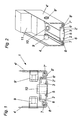
- Fig. 1 shows a cross-sectional view of the end face of a plate member 1.
- the front side has two spaced-apart metal profiles 2, 2 ', between which insulating material 3 is arranged. There is no metallic connection between the Metal profiles 2, 2 ', which would lead to an undesirable thermal coupling of a side wall 4 to the parallel opposite side wall 4'.
- the metal profiles 2, 2 ' embrace the essentially cuboidal insulating material 3 on its narrow side, the metal profiles 2, 2' embracing the edge of the insulating material 3 with a substantially U-shaped edge.
- the insulating material 3 is for example PU resin, which is poured in the manufacture in liquid form between the metal profiles 2, 2 '. To prevent leakage of the liquid resin, a piping 5 is provided. This plastic cover is removed after the curing of the insulating material 3 again.
- the metal profiles 2, 2 ' are at least partially double-walled, resulting in improved stability.
- the metal profiles 2, 2 ' include an insulating gap 6, 6', which causes an improved thermal decoupling.
- the metal profiles 2, 2 'grooves 7, 7' which are provided for receiving seals 8, 8 '.
- the metal profiles 2, 2 ' are each connected to a side wall 4, 4'. By this connection, a favorable strength of the plate element 1 is achieved.
- a further increase in strength is achieved by the rotting of the side walls 4, 4 'with the metal profiles 2, 2', wherein the side walls 4, 4 'at least partially in the grooves 7, 7' of the metal profiles 2, 2 'engage.
- sockets 10 are provided, which pass through the insulating material 3. These bushes 10 are used in the casting process of the insulating material 3 and serve to accommodate matching screws that are screwed, for example, from corresponding corner profiles 14 in the end face of the plate elements 1.
- Fig. 1 drawn socket 10 is provided only by way of example for a plurality of interspersing sockets 10, which are arranged at regular intervals on the front side of the plate elements 1.
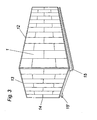
- Fig. 2 shows a three-dimensional representation of the in Fig. 1
- the spaced metal profiles 2, 2 ' enclose the narrow side of the insulating material 3 with a substantially U-shaped edge.
- the metal profiles 2, 2 ' have at least partially mutually parallel sections, between which an insulating gap 6, 6' remains.
- the metal profiles have channel-shaped sections 7, 7 ', which are provided for receiving circumferentially extending seals 8, 8'.
- insulation 11 between the side walls 4, 4 'rock wool is provided, for example, the next the insulation has good fire and noise-reducing properties.
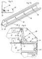
- Fig. 3 shows an RLT housing with plate elements 1 different standard sizes. Inside, the inclusion of ventilation and air conditioning systems is provided, which cause not only strong heat generation but also considerable noise emissions.
- the plate elements 1 according to the invention are provided, which are characterized by a frameless construction for a substantially thermally decoupled system.
- the individual plate elements 1 are connected to each other with the front side.
- the plate elements 1 are screwed, for example, with longitudinal bars 12 and transverse bars 13, at the corners vertical corner profiles 14 are provided which also have a thermally decoupled system as the plate elements 1.
- the housing can rest, for example, on U-shaped profile rails 15, 15 ', which is mounted vibration-damped by vibration-damping pads.
- Fig. 4 shows a schematically illustrated another embodiment of an RLT housing.
- the thermally separated plate elements 1 here have a standardized unit size.
- a corner profile 14 is provided, which has a substantially C-shaped section 19 made of metal, preferably made of steel, and a triangular corner strip 17 made of plastic, preferably polypropylene.
- plastic corner strip 17 can also be realized on the edge side thermal decoupling.
- the construction of the doors 16 is also thermally decoupled from the inside to the outside.
- the Fig. 4a shows a front view of the in Fig. 4 illustrated housing.
- the Fig. 4b shows a sectional view along the axis AA Fig. 4a with a detail C, on which in the Figure 6 will be discussed in more detail.
- Fig. 5 shows a schematic front view of a corner profile 14 with the C-shaped portion 19 made of metal and the triangular corner molding 17 made of plastic.
- the C-shaped portion 19 is connectable at its central part with the corner strip 17, preferably screwed to the screw 18 shown by way of example.
- Fig. 5a shows the corner profile 14 in a perspective view with corner strip 17 and metallic part 19, which are connected by screws 18.
- Fig. 6 shows detail C. Fig. 4b in an enlarged view.
- the corner profile 14 is provided, which has a substantially C-shaped portion 19 made of metal, preferably made of steel, and a triangular, corner strip 17 made of plastic.
- a cover strip 20 serves to cover the C-shaped section.
- the C-shaped portion 19 is connectable at its central part with the corner bar 17, for example by the screws 18. It is advantageous that the C-shaped portion 19 of the corner profile 14 of the inner metal profiles 2, 2 'of the plate elements 1, preferably through the corner bar 17, is spaced. This ensures that there is no metallic and therefore good heat-conducting connection of the inner metal profile 2 to the opposite metal profile 2 'and thus to the outer side wall 4'.
- a door 16 is exemplified, which is also thermally decoupled from the housing interior 21 to the outside.
- a plastic profile 22 is arranged with a rectangular cross-section. This plastic profile 22 may be glass fiber reinforced, for example.
- a door seal 24 is used for thermal decoupling, preferably an EPDM seal, which effects a thermal separation from the interior 21 of the housing to the outside.
- the present invention is not limited to the exemplary embodiments shown in the figures, nor should they be limited by them.
- other materials than mineral wool and PU resin can be used as insulation and as insulating material.
- the plastic corner strip in addition to the triangular shape shown in the figures, another geometry, such as a polygonal have.
Landscapes
- Engineering & Computer Science (AREA)
- Architecture (AREA)
- Civil Engineering (AREA)
- Structural Engineering (AREA)
- Building Environments (AREA)
- Cooling Or The Like Of Electrical Apparatus (AREA)
- Thermal Insulation (AREA)
- Air Filters, Heat-Exchange Apparatuses, And Housings Of Air-Conditioning Units (AREA)
- Duct Arrangements (AREA)
Claims (16)
- Élément panneau pour la construction modulaire de boîtiers, de préférence d'installations d'aération et de climatisation, avec deux parois latérales (4, 4') espacées et s'étendant essentiellement parallèlement dotées d'une isolation (11) disposée entre chacune et avec une face avant s'étendant à angle droit par rapport aux parois latérales autour de l'élément panneau, la face avant présentant dans la vue en section deux profilés métalliques (2, 2') espacés l'un de l'autre, entre lesquels de la matière isolante (3) est disposée, caractérisé en ce que la matière isolante (3) est traversée par des douilles (10) qui sont prévues pour la liaison avec des éléments panneaux (1) contigus et/ou pour la liaison avec des profils d'angle (14).
- Élément panneau selon la revendication 1, caractérisé en ce que la matière isolante (3) est réalisée essentiellement en forme de parallélépipède,
- Élément panneau selon la revendication 1 ou 2, caractérisé en ce que les profilés métalliques (2, 2') entourent la matière isolante (3) sur son petit côté.
- Élément panneau selon l'une quelconque des revendications 1 à 3, caractérisé en ce que les profilés métalliques (2, 2') entourent le bord de la matière isolante (3) avec un bord essentiellement en forme de U.
- Élément panneau selon l'une quelconque des revendications 1 à 4, caractérisé en ce que les profilés métalliques (2, 2') sont réalisés au moins en partie à double paroi.
- Élément panneau selon l'une quelconque des revendications 1 à 5, caractérisé en ce que les profilés métalliques (2, 2') présentent des sections s'étendant parallèlement, entre lesquelles reste une fente (6) isolante.
- Élément panneau selon l'une quelconque des revendications 1 à 6, caractérisé en ce que les profilés métalliques (2, 2') présentent des goulottes (7, 7') pour recevoir une garniture (8).
- Élément panneau selon la revendication 7, caractérisé en ce que la garniture (8) est une garniture en EPDM.
- Élément panneau selon l'une quelconque des revendications 1 à 8, caractérisé en ce que les profilés métalliques (2, 2') sont reliés chacun à une paroi latérale (4,4').
- Élément panneau selon la revendication 9, caractérisé en ce que des moyens de fixation (9, 9') mécaniques, de préférence des écrous rivés, sont prévus pour la liaison des profilés métalliques (2, 2') avec les parois latérales (4, 4').
- Élément panneau selon la revendication 9, caractérisé en ce que les parois latérales (4, 4') sont roulées au moins partiellement avec les profilés métalliques (2, 2').
- Élément panneau selon l'une quelconque des revendications 1 à 11, caractérisé en ce que la matière isolante (3) est une matière résistante à la chaleur et au feu, de préférence de la résine de PU.
- Élément panneau selon l'une quelconque des revendications 1 à 12, caractérisé en ce que l'isolation (11) entre les parois latérales (4, 4') est une matière résistante au feu et à la température, de préférence une laine minérale.
- Disposition d'au moins deux éléments panneaux selon l'une quelconque des revendications 1 à 13, caractérisée en ce qu'un profil d'angle (14) est prévu pour la liaison côté arête des éléments panneaux (1), lequel présente une section (19) essentiellement en forme de C en métal, de préférence en acier, et un listel d'angle (17) de préférence triangulaire en matière plastique.
- Disposition selon la revendication 14, caractérisée en ce que la section (19) en forme de C peut être reliée, de préférence vissée, sur sa partie médiane au listel d'angle (17).
- Disposition selon la revendication 14 ou 15, caractérisée en ce que la section (19) en forme de C du profil d'angle (14) est espacée des profilés métalliques (2, 2') intérieurs des éléments panneaux (1) de préférence par le listel d'angle (17).
Applications Claiming Priority (2)
| Application Number | Priority Date | Filing Date | Title |
|---|---|---|---|
| AT0171403A AT413408B (de) | 2003-10-29 | 2003-10-29 | Plattenelement zum modularen aufbau von gehäuse, vorzugsweise von lüftungs- und klimaanlagen |
| AT17142003 | 2003-10-29 |
Publications (2)
| Publication Number | Publication Date |
|---|---|
| EP1528186A1 EP1528186A1 (fr) | 2005-05-04 |
| EP1528186B1 true EP1528186B1 (fr) | 2008-05-21 |
Family
ID=34397361
Family Applications (1)
| Application Number | Title | Priority Date | Filing Date |
|---|---|---|---|
| EP04023654A Expired - Lifetime EP1528186B1 (fr) | 2003-10-29 | 2004-10-05 | Panneau pour la construction de logements modulaires particulièrement pour des unités de ventilation et conditionnement d'air |
Country Status (5)
| Country | Link |
|---|---|
| EP (1) | EP1528186B1 (fr) |
| CN (1) | CN100398933C (fr) |
| AT (2) | AT413408B (fr) |
| DE (1) | DE502004007211D1 (fr) |
| TW (1) | TW200523483A (fr) |
Families Citing this family (1)
| Publication number | Priority date | Publication date | Assignee | Title |
|---|---|---|---|---|
| CN106766077B (zh) * | 2017-03-21 | 2022-06-07 | 博纳环境设备(太仓)有限公司 | 组合式空调机组框架及其立柱 |
Family Cites Families (4)
| Publication number | Priority date | Publication date | Assignee | Title |
|---|---|---|---|---|
| US1697189A (en) * | 1927-06-13 | 1929-01-01 | Kirk & Blum Mfg Company | Heat-insulating structural element |
| DE3042109C2 (de) | 1980-11-07 | 1983-08-11 | Aeolos Holding AG, St.Gallen | Plattenelement zum Bau von Isolierkammern und -gehäusen für Lüftungs- und Klimaanlagen |
| DE3244743A1 (de) * | 1982-12-03 | 1984-06-07 | Karosserie- und Fahrzeugbau Werner Brandt, 4923 Extertal | Rollwand fuer kuehl- und isolierbehaelter |
| FR2604739A1 (fr) * | 1986-10-07 | 1988-04-08 | Cegedur | Panneau isolant |
-
2003
- 2003-10-29 AT AT0171403A patent/AT413408B/de not_active IP Right Cessation
-
2004
- 2004-10-05 AT AT04023654T patent/ATE396314T1/de not_active IP Right Cessation
- 2004-10-05 TW TW093130057A patent/TW200523483A/zh unknown
- 2004-10-05 DE DE502004007211T patent/DE502004007211D1/de not_active Expired - Fee Related
- 2004-10-05 EP EP04023654A patent/EP1528186B1/fr not_active Expired - Lifetime
- 2004-10-29 CN CNB2004100901733A patent/CN100398933C/zh not_active Expired - Fee Related
Also Published As
| Publication number | Publication date |
|---|---|
| TW200523483A (en) | 2005-07-16 |
| AT413408B (de) | 2006-02-15 |
| CN1619233A (zh) | 2005-05-25 |
| CN100398933C (zh) | 2008-07-02 |
| DE502004007211D1 (de) | 2008-07-03 |
| EP1528186A1 (fr) | 2005-05-04 |
| ATA17142003A (de) | 2005-07-15 |
| TWI319057B (fr) | 2010-01-01 |
| ATE396314T1 (de) | 2008-06-15 |
Similar Documents
| Publication | Publication Date | Title |
|---|---|---|
| EP1024243B1 (fr) | Connection resistante au feu avec âme isolante | |
| EP0117308B1 (fr) | Profil creux en matière synthétique renforcé par un profil métallique et châssis | |
| EP4495366B1 (fr) | Construction composite pour éléments de surface fixes et mobiles | |
| DE69013864T2 (de) | Wärmeisolierendes und feuerhemmendes Wandpaneel. | |
| DE3438861A1 (de) | Verbundprofil zur herstellung von fenster-, tuerrahmen, fassadenkonstruktionen u.dgl. | |
| EP0775789A1 (fr) | Elément de construction en verre formé d'une unité composite à vitres multiples avec une mesure de protection de bords | |
| EP1528186B1 (fr) | Panneau pour la construction de logements modulaires particulièrement pour des unités de ventilation et conditionnement d'air | |
| EP2573307A1 (fr) | Système de cadre de profilé en plusieurs parties pour portes, portails, jardins d'hiver et fenêtres | |
| EP0124807B1 (fr) | Cabine | |
| DE29880053U1 (de) | Profilsystem zur Herstellung von Fenstern oder Türen | |
| EP0279820B1 (fr) | Elements de panneaux prefabriques pour la realisation de chambres isolantes | |
| DE102008063482A1 (de) | Gehäuse für Lüftungs- und Klimageräte | |
| EP0430921A1 (fr) | Mur fait à partir de panneaux en forme de boîte | |
| EP1152194B1 (fr) | Joint d'angle pour un cadre de boítier d'un dispositif de climatisation | |
| DE29608643U1 (de) | Wagenkasten eines Schienenfahrzeuges | |
| EP2803804A2 (fr) | Porte | |
| AT522638B1 (de) | Profil | |
| DE29712751U1 (de) | Rahmenkonstruktion | |
| EP1004739B1 (fr) | Arrangement isolant pour profilés en aluminium | |
| EP4039904A1 (fr) | Salle blanche | |
| DE19627121C2 (de) | Verbundprofil | |
| DE19654048C2 (de) | Doppelwandiger Behälter mit einer Innenwand und einer Außenwand aus einem thermisch gut leitenden Material, insbesondere für Kühlschränke und Wärmeschränke | |
| DE20121414U1 (de) | Schutzgehäuse, insbesondere Instrumentenschutzhaus | |
| DE2718839A1 (de) | Feuerfester kanal | |
| EP1681430A2 (fr) | Profilé composite pour cadres d'éléments de paroi, portes et fenêtres |
Legal Events
| Date | Code | Title | Description |
|---|---|---|---|
| PUAI | Public reference made under article 153(3) epc to a published international application that has entered the european phase |
Free format text: ORIGINAL CODE: 0009012 |
|
| AK | Designated contracting states |
Kind code of ref document: A1 Designated state(s): AT BE BG CH CY CZ DE DK EE ES FI FR GB GR HU IE IT LI LU MC NL PL PT RO SE SI SK TR |
|
| AX | Request for extension of the european patent |
Extension state: AL HR LT LV MK |
|
| 17P | Request for examination filed |
Effective date: 20050811 |
|
| AKX | Designation fees paid |
Designated state(s): AT BE BG CH CY CZ DE DK EE ES FI FR GB GR HU IE IT LI LU MC NL PL PT RO SE SI SK TR |
|
| 17Q | First examination report despatched |
Effective date: 20071122 |
|
| GRAP | Despatch of communication of intention to grant a patent |
Free format text: ORIGINAL CODE: EPIDOSNIGR1 |
|
| GRAS | Grant fee paid |
Free format text: ORIGINAL CODE: EPIDOSNIGR3 |
|
| GRAA | (expected) grant |
Free format text: ORIGINAL CODE: 0009210 |
|
| AK | Designated contracting states |
Kind code of ref document: B1 Designated state(s): AT BE BG CH CY CZ DE DK EE ES FI FR GB GR HU IE IT LI LU MC NL PL PT RO SE SI SK TR |
|
| REG | Reference to a national code |
Ref country code: GB Ref legal event code: FG4D Free format text: NOT ENGLISH |
|
| REG | Reference to a national code |
Ref country code: CH Ref legal event code: EP |
|
| REF | Corresponds to: |
Ref document number: 502004007211 Country of ref document: DE Date of ref document: 20080703 Kind code of ref document: P |
|
| REG | Reference to a national code |
Ref country code: IE Ref legal event code: FG4D Free format text: LANGUAGE OF EP DOCUMENT: GERMAN |
|
| PG25 | Lapsed in a contracting state [announced via postgrant information from national office to epo] |
Ref country code: SI Free format text: LAPSE BECAUSE OF FAILURE TO SUBMIT A TRANSLATION OF THE DESCRIPTION OR TO PAY THE FEE WITHIN THE PRESCRIBED TIME-LIMIT Effective date: 20080521 |
|
| PG25 | Lapsed in a contracting state [announced via postgrant information from national office to epo] |
Ref country code: ES Free format text: LAPSE BECAUSE OF FAILURE TO SUBMIT A TRANSLATION OF THE DESCRIPTION OR TO PAY THE FEE WITHIN THE PRESCRIBED TIME-LIMIT Effective date: 20080901 Ref country code: FI Free format text: LAPSE BECAUSE OF FAILURE TO SUBMIT A TRANSLATION OF THE DESCRIPTION OR TO PAY THE FEE WITHIN THE PRESCRIBED TIME-LIMIT Effective date: 20080521 |
|
| NLV1 | Nl: lapsed or annulled due to failure to fulfill the requirements of art. 29p and 29m of the patents act | ||
| PG25 | Lapsed in a contracting state [announced via postgrant information from national office to epo] |
Ref country code: PL Free format text: LAPSE BECAUSE OF FAILURE TO SUBMIT A TRANSLATION OF THE DESCRIPTION OR TO PAY THE FEE WITHIN THE PRESCRIBED TIME-LIMIT Effective date: 20080521 Ref country code: NL Free format text: LAPSE BECAUSE OF FAILURE TO SUBMIT A TRANSLATION OF THE DESCRIPTION OR TO PAY THE FEE WITHIN THE PRESCRIBED TIME-LIMIT Effective date: 20080521 |
|
| REG | Reference to a national code |
Ref country code: IE Ref legal event code: FD4D |
|
| PG25 | Lapsed in a contracting state [announced via postgrant information from national office to epo] |
Ref country code: IE Free format text: LAPSE BECAUSE OF FAILURE TO SUBMIT A TRANSLATION OF THE DESCRIPTION OR TO PAY THE FEE WITHIN THE PRESCRIBED TIME-LIMIT Effective date: 20080521 Ref country code: CZ Free format text: LAPSE BECAUSE OF FAILURE TO SUBMIT A TRANSLATION OF THE DESCRIPTION OR TO PAY THE FEE WITHIN THE PRESCRIBED TIME-LIMIT Effective date: 20080521 Ref country code: PT Free format text: LAPSE BECAUSE OF FAILURE TO SUBMIT A TRANSLATION OF THE DESCRIPTION OR TO PAY THE FEE WITHIN THE PRESCRIBED TIME-LIMIT Effective date: 20081021 Ref country code: DK Free format text: LAPSE BECAUSE OF FAILURE TO SUBMIT A TRANSLATION OF THE DESCRIPTION OR TO PAY THE FEE WITHIN THE PRESCRIBED TIME-LIMIT Effective date: 20080521 Ref country code: SE Free format text: LAPSE BECAUSE OF FAILURE TO SUBMIT A TRANSLATION OF THE DESCRIPTION OR TO PAY THE FEE WITHIN THE PRESCRIBED TIME-LIMIT Effective date: 20080821 |
|
| PG25 | Lapsed in a contracting state [announced via postgrant information from national office to epo] |
Ref country code: RO Free format text: LAPSE BECAUSE OF FAILURE TO SUBMIT A TRANSLATION OF THE DESCRIPTION OR TO PAY THE FEE WITHIN THE PRESCRIBED TIME-LIMIT Effective date: 20080521 Ref country code: SK Free format text: LAPSE BECAUSE OF FAILURE TO SUBMIT A TRANSLATION OF THE DESCRIPTION OR TO PAY THE FEE WITHIN THE PRESCRIBED TIME-LIMIT Effective date: 20080521 |
|
| PLBE | No opposition filed within time limit |
Free format text: ORIGINAL CODE: 0009261 |
|
| STAA | Information on the status of an ep patent application or granted ep patent |
Free format text: STATUS: NO OPPOSITION FILED WITHIN TIME LIMIT |
|
| 26N | No opposition filed |
Effective date: 20090224 |
|
| BERE | Be: lapsed |
Owner name: EUROCLIMA APPARATEBAU GMBH Effective date: 20081031 |
|
| PG25 | Lapsed in a contracting state [announced via postgrant information from national office to epo] |
Ref country code: BG Free format text: LAPSE BECAUSE OF FAILURE TO SUBMIT A TRANSLATION OF THE DESCRIPTION OR TO PAY THE FEE WITHIN THE PRESCRIBED TIME-LIMIT Effective date: 20080821 Ref country code: EE Free format text: LAPSE BECAUSE OF FAILURE TO SUBMIT A TRANSLATION OF THE DESCRIPTION OR TO PAY THE FEE WITHIN THE PRESCRIBED TIME-LIMIT Effective date: 20080521 |
|
| PG25 | Lapsed in a contracting state [announced via postgrant information from national office to epo] |
Ref country code: MC Free format text: LAPSE BECAUSE OF NON-PAYMENT OF DUE FEES Effective date: 20081031 |
|
| REG | Reference to a national code |
Ref country code: CH Ref legal event code: PL |
|
| GBPC | Gb: european patent ceased through non-payment of renewal fee |
Effective date: 20081005 |
|
| REG | Reference to a national code |
Ref country code: FR Ref legal event code: ST Effective date: 20090630 |
|
| PG25 | Lapsed in a contracting state [announced via postgrant information from national office to epo] |
Ref country code: DE Free format text: LAPSE BECAUSE OF NON-PAYMENT OF DUE FEES Effective date: 20090501 Ref country code: IT Free format text: LAPSE BECAUSE OF FAILURE TO SUBMIT A TRANSLATION OF THE DESCRIPTION OR TO PAY THE FEE WITHIN THE PRESCRIBED TIME-LIMIT Effective date: 20080521 |
|
| PG25 | Lapsed in a contracting state [announced via postgrant information from national office to epo] |
Ref country code: BE Free format text: LAPSE BECAUSE OF NON-PAYMENT OF DUE FEES Effective date: 20081031 |
|
| PG25 | Lapsed in a contracting state [announced via postgrant information from national office to epo] |
Ref country code: LI Free format text: LAPSE BECAUSE OF NON-PAYMENT OF DUE FEES Effective date: 20081031 Ref country code: FR Free format text: LAPSE BECAUSE OF NON-PAYMENT OF DUE FEES Effective date: 20081031 Ref country code: CH Free format text: LAPSE BECAUSE OF NON-PAYMENT OF DUE FEES Effective date: 20081031 |
|
| PG25 | Lapsed in a contracting state [announced via postgrant information from national office to epo] |
Ref country code: GB Free format text: LAPSE BECAUSE OF NON-PAYMENT OF DUE FEES Effective date: 20081005 |
|
| PGFP | Annual fee paid to national office [announced via postgrant information from national office to epo] |
Ref country code: AT Payment date: 20091014 Year of fee payment: 6 |
|
| PG25 | Lapsed in a contracting state [announced via postgrant information from national office to epo] |
Ref country code: LU Free format text: LAPSE BECAUSE OF NON-PAYMENT OF DUE FEES Effective date: 20081005 Ref country code: HU Free format text: LAPSE BECAUSE OF FAILURE TO SUBMIT A TRANSLATION OF THE DESCRIPTION OR TO PAY THE FEE WITHIN THE PRESCRIBED TIME-LIMIT Effective date: 20081122 Ref country code: CY Free format text: LAPSE BECAUSE OF FAILURE TO SUBMIT A TRANSLATION OF THE DESCRIPTION OR TO PAY THE FEE WITHIN THE PRESCRIBED TIME-LIMIT Effective date: 20080521 |
|
| PG25 | Lapsed in a contracting state [announced via postgrant information from national office to epo] |
Ref country code: TR Free format text: LAPSE BECAUSE OF FAILURE TO SUBMIT A TRANSLATION OF THE DESCRIPTION OR TO PAY THE FEE WITHIN THE PRESCRIBED TIME-LIMIT Effective date: 20080521 |
|
| PG25 | Lapsed in a contracting state [announced via postgrant information from national office to epo] |
Ref country code: GR Free format text: LAPSE BECAUSE OF FAILURE TO SUBMIT A TRANSLATION OF THE DESCRIPTION OR TO PAY THE FEE WITHIN THE PRESCRIBED TIME-LIMIT Effective date: 20080822 |
|
| PG25 | Lapsed in a contracting state [announced via postgrant information from national office to epo] |
Ref country code: AT Free format text: LAPSE BECAUSE OF NON-PAYMENT OF DUE FEES Effective date: 20101005 |