EP1527959A1 - Dispositif de retenue des occupants d'un véhicule - Google Patents
Dispositif de retenue des occupants d'un véhicule Download PDFInfo
- Publication number
- EP1527959A1 EP1527959A1 EP04024966A EP04024966A EP1527959A1 EP 1527959 A1 EP1527959 A1 EP 1527959A1 EP 04024966 A EP04024966 A EP 04024966A EP 04024966 A EP04024966 A EP 04024966A EP 1527959 A1 EP1527959 A1 EP 1527959A1
- Authority
- EP
- European Patent Office
- Prior art keywords
- vehicle
- sensitivity
- collision
- predicting
- devices
- Prior art date
- Legal status (The legal status is an assumption and is not a legal conclusion. Google has not performed a legal analysis and makes no representation as to the accuracy of the status listed.)
- Granted
Links
Images


Classifications
-
- B—PERFORMING OPERATIONS; TRANSPORTING
- B60—VEHICLES IN GENERAL
- B60R—VEHICLES, VEHICLE FITTINGS, OR VEHICLE PARTS, NOT OTHERWISE PROVIDED FOR
- B60R21/00—Arrangements or fittings on vehicles for protecting or preventing injuries to occupants or pedestrians in case of accidents or other traffic risks
- B60R21/01—Electrical circuits for triggering passive safety arrangements, e.g. airbags, safety belt tighteners, in case of vehicle accidents or impending vehicle accidents
- B60R21/013—Electrical circuits for triggering passive safety arrangements, e.g. airbags, safety belt tighteners, in case of vehicle accidents or impending vehicle accidents including means for detecting collisions, impending collisions or roll-over
-
- B—PERFORMING OPERATIONS; TRANSPORTING
- B60—VEHICLES IN GENERAL
- B60R—VEHICLES, VEHICLE FITTINGS, OR VEHICLE PARTS, NOT OTHERWISE PROVIDED FOR
- B60R19/00—Wheel guards; Radiator guards, e.g. grilles; Obstruction removers; Fittings damping bouncing force in collisions
- B60R19/02—Bumpers, i.e. impact receiving or absorbing members for protecting vehicles or fending off blows from other vehicles or objects
- B60R19/24—Arrangements for mounting bumpers on vehicles
- B60R19/38—Arrangements for mounting bumpers on vehicles adjustably or movably mounted, e.g. horizontally displaceable for securing a space between parked vehicles
- B60R19/40—Arrangements for mounting bumpers on vehicles adjustably or movably mounted, e.g. horizontally displaceable for securing a space between parked vehicles in the direction of an obstacle before a collision, or extending during driving of the vehicle, i.e. to increase the energy absorption capacity of the bumper
-
- B—PERFORMING OPERATIONS; TRANSPORTING
- B60—VEHICLES IN GENERAL
- B60R—VEHICLES, VEHICLE FITTINGS, OR VEHICLE PARTS, NOT OTHERWISE PROVIDED FOR
- B60R21/00—Arrangements or fittings on vehicles for protecting or preventing injuries to occupants or pedestrians in case of accidents or other traffic risks
- B60R21/01—Electrical circuits for triggering passive safety arrangements, e.g. airbags, safety belt tighteners, in case of vehicle accidents or impending vehicle accidents
- B60R2021/01034—Controlling a plurality of restraint devices
-
- B—PERFORMING OPERATIONS; TRANSPORTING
- B60—VEHICLES IN GENERAL
- B60R—VEHICLES, VEHICLE FITTINGS, OR VEHICLE PARTS, NOT OTHERWISE PROVIDED FOR
- B60R21/00—Arrangements or fittings on vehicles for protecting or preventing injuries to occupants or pedestrians in case of accidents or other traffic risks
- B60R21/01—Electrical circuits for triggering passive safety arrangements, e.g. airbags, safety belt tighteners, in case of vehicle accidents or impending vehicle accidents
- B60R21/013—Electrical circuits for triggering passive safety arrangements, e.g. airbags, safety belt tighteners, in case of vehicle accidents or impending vehicle accidents including means for detecting collisions, impending collisions or roll-over
- B60R21/0132—Electrical circuits for triggering passive safety arrangements, e.g. airbags, safety belt tighteners, in case of vehicle accidents or impending vehicle accidents including means for detecting collisions, impending collisions or roll-over responsive to vehicle motion parameters, e.g. to vehicle longitudinal or transversal deceleration or speed value
- B60R2021/01322—Electrical circuits for triggering passive safety arrangements, e.g. airbags, safety belt tighteners, in case of vehicle accidents or impending vehicle accidents including means for detecting collisions, impending collisions or roll-over responsive to vehicle motion parameters, e.g. to vehicle longitudinal or transversal deceleration or speed value comprising variable thresholds, e.g. depending from other collision parameters
-
- B—PERFORMING OPERATIONS; TRANSPORTING
- B60—VEHICLES IN GENERAL
- B60R—VEHICLES, VEHICLE FITTINGS, OR VEHICLE PARTS, NOT OTHERWISE PROVIDED FOR
- B60R22/00—Safety belts or body harnesses in vehicles
- B60R22/34—Belt retractors, e.g. reels
- B60R22/46—Reels with means to tension the belt in an emergency by forced winding up
- B60R2022/4666—Reels with means to tension the belt in an emergency by forced winding up characterised by electric actuators
-
- B—PERFORMING OPERATIONS; TRANSPORTING
- B60—VEHICLES IN GENERAL
- B60R—VEHICLES, VEHICLE FITTINGS, OR VEHICLE PARTS, NOT OTHERWISE PROVIDED FOR
- B60R21/00—Arrangements or fittings on vehicles for protecting or preventing injuries to occupants or pedestrians in case of accidents or other traffic risks
- B60R21/01—Electrical circuits for triggering passive safety arrangements, e.g. airbags, safety belt tighteners, in case of vehicle accidents or impending vehicle accidents
- B60R21/013—Electrical circuits for triggering passive safety arrangements, e.g. airbags, safety belt tighteners, in case of vehicle accidents or impending vehicle accidents including means for detecting collisions, impending collisions or roll-over
- B60R21/0134—Electrical circuits for triggering passive safety arrangements, e.g. airbags, safety belt tighteners, in case of vehicle accidents or impending vehicle accidents including means for detecting collisions, impending collisions or roll-over responsive to imminent contact with an obstacle, e.g. using radar systems
-
- B—PERFORMING OPERATIONS; TRANSPORTING
- B60—VEHICLES IN GENERAL
- B60R—VEHICLES, VEHICLE FITTINGS, OR VEHICLE PARTS, NOT OTHERWISE PROVIDED FOR
- B60R21/00—Arrangements or fittings on vehicles for protecting or preventing injuries to occupants or pedestrians in case of accidents or other traffic risks
- B60R21/02—Occupant safety arrangements or fittings, e.g. crash pads
- B60R21/16—Inflatable occupant restraints or confinements designed to inflate upon impact or impending impact, e.g. air bags
- B60R21/33—Arrangements for non-electric triggering of inflation
-
- B—PERFORMING OPERATIONS; TRANSPORTING
- B60—VEHICLES IN GENERAL
- B60R—VEHICLES, VEHICLE FITTINGS, OR VEHICLE PARTS, NOT OTHERWISE PROVIDED FOR
- B60R22/00—Safety belts or body harnesses in vehicles
- B60R22/18—Anchoring devices
- B60R22/195—Anchoring devices with means to tension the belt in an emergency, e.g. means of the through-anchor or splitted reel type
- B60R22/1954—Anchoring devices with means to tension the belt in an emergency, e.g. means of the through-anchor or splitted reel type characterised by fluid actuators, e.g. pyrotechnic gas generators
Definitions
- the present invention relates in general to passenger restraint devices of wheeled motor vehicles and more particularly to the passenger restraint devices of a type that includes at least a seat belt and a controller that is configured to control a set position of the seat belt in such a manner that a seat occupant (viz., belt wearing seat occupant) can be safely restrained by the seat belt upon a vehicle collision.
- Japanese Laid-open Patent Applications (Tokkaihei) 6-286581 and (Tokkai) 2003-175797 show passenger restraint devices of the above-mentioned type.
- the devices each comprise a seat belt for restraining a seat occupant, first and second pre-tensioners for applying a certain tension to the seat belt and a controller for controlling the first and second pre-tensioners in accordance with prediction and detection of a vehicle collision.
- the first pre-tensioner is of a reversible (or repeatable) type and the second pre-tensioner is of a non-reversible (or non-repeatable) type.
- the controller actuates the first pre-tensioner and upon detecting the vehicle collision, the controller actuates the second pre-tensioner, so that a belt wearing seat occupant is timely and optimally restrained by the seat belt upon the vehicle collision.
- operation of the seat occupant restraint device is controlled in accordance with prediction and/or detection of a vehicle collision.
- the above-mentioned control based on the prediction and/or detection of a vehicle collision tends to fail to exhibit a satisfied safety operation particularly in a case wherein a plurality of seat occupant restraining devices are arranged to be controlled. That is, there is such a possibility that although one of the seat occupant restraining devices can be optimally controlled, the other restraining devices can not be optimally controlled.
- the passenger restraint devices hitherto proposed still have room for improvement in the operation of the seat occupant restraining devices.
- a passenger restraint device of a motor vehicle comprises a plurality of predicting devices each being able to predict or detect a collision of the vehicle with an obstacle in front of the vehicle; a sensitivity adjusting device that is able to adjust a sensitivity of at least one of the predicting devices; reversible passenger restraining devices that are able to reversibly restrain a passenger in the vehicle; non-reversible passenger restraining devices that are able to non-reversibly restrain the passenger in the vehicle; and a control unit that, based on a signal from the one of the predicting devices that has been subjected to the sensitivity adjustment by the sensitivity adjusting device, controls operation of the reversible and non-reversible passenger restraining devices.
- a passenger restraint device of a motor vehicle which comprises a plurality of predicting devices each being able to predict or detect a collision of the vehicle with an obstacle in front of the vehicle; sensitivity adjusting means that adjusts a sensitivity of at least one of the predicting devices; reversible passenger restraining means that reversibly restrain a passenger in the vehicle; non-reversible passenger restraining means that non-reversibly restrain the passenger; and control means that, based on a signal issued from the one of the predicting devices that has been subjected to the sensitivity adjustment by the sensitivity adjusting means, controls operation of the reversible and non-reversible passenger restraining means.
- a vehicle on which a passenger restraint device of the invention is mounted will be called “host vehicle” and a vehicle that runs ahead of the host vehicle will be called “preceding vehicle”, in the following.
- a passenger restraint device 100 which is a first embodiment of the present invention.
- passenger restraint device 100 comprises a long distance radar system 10 mounted on a front part of the host vehicle and a short distance radar system 11 mounted on the front part of the vehicle.
- each of these two distance radar systems 10 and 11 detects a distance between the host vehicle and a preceding vehicle (or forward obstacle) that runs ahead of the host vehicle.
- Each radar system 10 or 11 emits an electromagnetic wave against the preceding vehicle and receives a reflected wave from the preceding vehicle, and calculates a distance between the two vehicles by processing a timing of emitting the wave and a timing of receiving the reflected wave.
- the maximum distance detected by short distance radar system 11 is shorter than that detected by long distance radar system 10.
- the distance detected by long/short distance radar system 10 or 11 is processed by a control unit 40 for predicting a vehicle collision.
- a light beam type detector, an ultrasonic wave type detector and the like may be used in place of the radar type.
- Passenger restraint device 100 further comprises an accelerometer 20 that detects a collision of the host vehicle with the preceding vehicle. That is, accelerometer 20 detects an abnormally big deceleration of the host vehicle that would be produced when the host vehicle collides against the preceding vehicle.
- Passenger restraint device 100 further comprises a passenger restraining unit 30.
- Passenger restraining unit 30 comprises a knee bolster 31 that restrains a knee portion of the seat occupant, a motor driven retractor 32 that retracts a seatbelt by an electric power, an air bag 33 that restrains an upper portion of the seat occupant and a cartridge activated retractor 34 that retracts the seatbelt by force of explosive.
- knee bolster 31 and motor driven retractor 32 are of a reversible (or repeatable) type
- air bag 33 and cartridge activated retractor 34 are of a non-reversible (or non-repeatable) type.
- passenger restraining unit 30 comprises two types of passenger restraining devices, one being of the reversible type and the other being of the non-reversible type.
- Passenger restraint device 100 further comprises a control unit 40 that controls four restraining devices 31, 32, 33 and 34 of a passenger restraining unit 30 by processing information signals from long and short distance radar systems 10 and 11 and accelerometer 20. That is, the four restraining devices that are knee bolster 31, motor driven retractor 32, air bag 33 and cartridge activated retractor 34 are controlled by control unit 40 based on the information signals from long and short distance radar systems 10 and 11 and accelerometer 20.
- Control unit 40 is a micro-computer that generally comprises a CPU (central processing unit), a RAM (random access memory), a ROM (read only memory) and input and output interfaces. As will become apparent hereinafter, by processing the information signals, control unit 40 carries out a vehicle collision prediction judgment and a vehicle collision detection judgment.
- CPU central processing unit
- RAM random access memory
- ROM read only memory
- control unit 40 comprises a collision prediction judgment section (C.P.J.S) 41, a sensitivity adjusting section (S.A.S.) 42, a collision detection judgment section (C.D.J.S) 43, an operation timing deciding section (O.T.D.S.) 44 and four drive instruction sections 45a, 45b, 45c and 45d.
- C.P.J.S collision prediction judgment section
- S.A.S. sensitivity adjusting section
- O.T.D.S. operation timing deciding section
- collision prediction judgment section 41 carries out a prediction as to whether the host vehicle collides against the preceding vehicle or not.
- sensitivity adjusting section 42 adjusts the sensitivity of at least one of long and short distance radar systems 10 and 11 and accelerometer 20. In the illustrated embodiment, sensitivity adjusting section 42 adjusts the sensitivity of short distance radar system 11 based on the information signal from long distance radar system 10.
- collision detection judgment section 43 Upon processing information signals from accelerometer 20, collision detection judgment section 43 carries out a judgment as to whether a collision of the host vehicle against the preceding vehicle has actually occurred or not.
- operation timing deciding section 44 decides operation timings of knee bolster 31, motor driven retractor 32, air bag 33 and cartridge activated retractor 34.
- the instruction signals from operation timing deciding section 44 are led to drive instruction sections 45a, 45b, 45c and 45d to drive motor driven retractor 32, knee bolster 31, cartridge activated retractor 34 and air bag 33 respectively in accordance with the operation timings decided by the section 44.
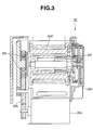
- Fig. 3 shows the detail of motor driven retractor 32 which has in addition to known basic elements an electric motor 32a, a speed reduction gear 32b and planetary gears 32c. That is, upon energization of electric motor 32a, a torque of motor 32a is transmitted to speed reduction gear 32b and to planetary gears 32c. The torque of which speed has been reduced by speed reduction gear 32b is applied through planetary gears 32c to a real 32d thereby to wind up thereon the seatbelt.
- Motor driven retractor 32 further has a lock gear 32e and a lock mechanism 32f. Due to provision of lock gear 32e and lock mechanism 32f, withdrawing of the seat belt from retractor 32 is suppressed at the time when, due to a vehicle collision or the like, an abnormally big shock is applied to retractor 32.
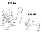
- Figs. 4A and 4B show electric knee bolster 31.
- knee bolster 31 comprises an electric motor 31a, a gear assembly 31b and a cylinder assembly 31c which are installed in an interior panel in front of a seat, and a bolster pad 31d which is connected to cylinder assembly 31c.
- gear assembly 31b upon energization of electric motor 31a, gear assembly 31b is operated to push or draw bolster pad 31d through cylinder assembly 31c.
- bolster pad 31d is kept in a cover member of the interior panel.
- electric motor 31a is energized to instantly push out bolster pad 31d to support the knee portion of the seat occupant. With this, forward movement of the seat occupant is assuredly suppressed. While, upon being free from the collision threat, such as in case wherein the possibility of the vehicle collision is removed thereafter, bolster pad 31d is instantly drawn to a retracted position.
- air bag 33 comprises an air bag proper and a gas generator. That is, upon a vehicle collision, the gas generator is energized to instantly fill the air bag proper with a gas. With this, the upper half portion of the seat occupant is softly supported by the air bag proper.
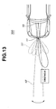
- Cartridge activated retractor 34 is constructed to make an instant but small winding of the seat belt by force of explosive upon a vehicle collision. That is, upon the vehicle collision, explosive in the cartridge is burnt to produce a big force with which the seat belt is retracted by a reel. With this, as is seen from Fig. 1, the upper half portion of the seat occupant is suppressed from inclining largely in a forward direction.
- each radar system 10 or 11 is arranged to emit an electromagnetic wave forward, that is, toward a preceding vehicle that runs ahead of the host vehicle, and receive a reflected wave from the preceding vehicle.
- the timing on which the wave is issued from radar system 10 or 11 and that on which the reflected wave is received by radar system 10 or 11 are monitored and inputted to collision prediction judgment section 41 of control unit 40.
- collision prediction judgment section 41 calculates or estimates a distance between the host vehicle and the preceding vehicle (or forward obstacle). By differentiating the calculated distance by time, the section 41 derives a relative vehicle speed between the host vehicle and the preceding vehicle (or forward obstacle). If desired, the relative speed may be obtained by practically using Doppler effect. By dividing the estimated distance by the relative vehicle speed, the section 41 derives a time on which a possible collision of the host vehicle against the preceding vehicle (or forward obstacle) will take place.
- Accelerometer 20 is arranged to measure an acceleration that is applied to the vehicle in a forward and backward direction.
- the acceleration representing signal from accelerometer 20 is fed to collision detection judgment section 43 of control unit 40.
- the section 43 judges whether the vehicle collision has occurred or not.
- passenger restraint device 100 When, an ignition switch (not shown) is turned on for staring the engine, passenger restraint device 100 becomes on. Upon this, long and short distance radar systems 10 and 11 and accelerometer 20 are turned on.
- step ST10 information signal from long distance radar system (that is, L. D. R. S.) 10 is read in collision prediction judgment section 41.
- step ST11 based on the information signal from the system 10, the section 41 carries out judgment as to whether a collision of the host vehicle with a preceding vehicle (or obstacle) will take place or not. If NO, that is, when it is judged that the collision will not take place, the operation flow goes to step ST13 which will be described hereinafter. While, if YES at step ST11, that is, when it is judged that collision will take place, the operation flow goes to step ST12 where collision prediction judgment section 41 issues a corresponding signal to sensitivity adjusting section 42 to adjust the sensitivity of short distance radar system (or S.D.R.S) 11. Then, the operation flow goes to step ST13.
- step ST13 information signal from short distance radar system 11 is read in collision prediction judgment section 41.
- step ST14 based on the information signal from the system 11, the section 41 carries out judgment as to whether a collision of the host vehicle with the preceding vehicle (or forward obstacle) will take place or not. If NO, that is, when it is judged that the collision will not take place, the operation flow goes back to step ST10. While, if YES at step ST14, the operation flow goes to step ST15.
- collision prediction judgment section 41 outputs a judgment result based on the information from short distance radar system 11.
- step ST15 information signal from accelerometer 20 is read in collision detection judgment section 43. Then the operation flow goes to step ST16.
- the section 43 judges whether the vehicle collision has actually taken place or not. If NO, that is, when it is judged that the collision has not taken place, the operation flow goes back to step ST10. While, if YES, that is, when it is judged that the collision has taken place actually, the operation flow goes to step ST17.
- operation timings of knee bolster 31, motor driven retractor 32, air bag 33 and cartridge activated retractor 34 are decided in operation timing deciding section 44.
- the devices 31, 32, 33 and 34 are actuated by the four drive instruction sections 45b, 45a, 45d and 45c at the timings decided at step ST17.
- step ST19 judgment is carried out as to whether the ignition switch has been turn off or not. If NO, that is, when the ignition switch is kept ON, the operation flow goes back to step ST10. While, if YES, that is, it is judged that the ignition switch has been turn off, the operation is ended.
- the detecting range of the radar system 11 is increased. That is, upon adjustment of the sensitivity, the detecting ability of short distance radar system 11 is raised.
- the sensitivity adjustment of short distance radar system 11 is carried out in a case wherein a vehicle collision is predicted based on the information signal issued from long distance radar system 10. It is to be noted that the possibility of the vehicle collision is higher in case wherein the collision is predicted based on the information signal from long distance radar system 10 than in case wherein such collision is not predicted based on the information signal from long distance radar system 10. That is, the sensitivity of the radar system 11 is increased when a possibility of vehicle collision is high. In other words, upon having a higher possibility of the vehicle collision, short distance radar system 11 is changed to have a longer detecting range.
- the prediction of vehicle collision is reliably carried out even if the vehicle is under a higher speed cruising and/or the vehicle has a very poor visibility owing to the dense fog.
- short distance radar system 11 can detect a preceding vehicle (or obstacle) in early stages while carrying out a high precision vehicle collision prediction.
- the detecting range of the radar system 11 can be adjusted by varying a wave transmission intensity and/or wave receiving sensitivity.
- the sensitivity may be adjusted by changing the contents of collision prediction judgment section 41 of control unit 40.
- One example is as follows.
- the section 41 memorizes a threshold value "Th2".
- collision prediction judgment section 41 predicts the vehicle collision when the calculated time is judged shorter than the threshold value "Th2".
- step ST17 of the flowchart of Fig. 6 will be described with reference to Fig. 8.
- FIG. 8 shows operation steps of the operating timing judging treatment carried out in operation timing deciding section 44 of control unit 40 of Fig. 2.
- step ST20 based on information signal from short distance radar system 11, judgment is carried out as to whether a vehicle collision has been predicted or not. More specifically, based on a result provided by collision prediction judgment section 41 based on the information from short distance radar system 11, operation timing deciding section 44 judges a possibility of vehicle collision.
- step ST20 that is, when collision prediction judgment section 41 judges a high possibility of vehicle collision, the operation flow goes to step ST21.
- operation timing deciding section 44 carries out judgment as to whether the predicted collision would occur within 1 second or not. If NO, that is, when it is judged that the predicted collision would not occur within 1.0 second, the operation flow goes back to step ST18 of the above-mentioned flowchart of Fig. 6.
- step ST21 While, if YES at step ST21, that is, when it is judged that the vehicle collision would occur within 1.0 second, the operation flow goes to step ST22 judging that knee bolster 31 should be operated. At this step, corresponding instruction signal is fed to knee bolster drive instruction section 45b for the operation of knee bolster 31.
- step ST23 operation timing deciding section 44 carries out judgment as to whether the predicted collision would occur within 0.5 second or not.
- step ST23 While, if YES at step ST23, that is, when it is judged that the vehicle collision would occur within 0.5 second, the operation flow goes to step ST24 judging that motor driven retractor 32 should be operated. At this step, corresponding instruction signal is fed to motor driven retractor drive instruction section (M.D.R.D.I.S.) 45a for operation of the retractor 32.
- M.D.R.D.I.S. motor driven retractor drive instruction section
- step ST25 operation timing deciding section 44 carries out judgment as to whether the vehicle collision has been detected or not. That is, the section 44 judges whether the information signal from collision detection judgment section 43 indicates a vehicle collision or not.
- step ST25 While, if YES at step ST25, that is, when it is judged that the vehicle collision has occurred, the operation flow goes to step ST26 judging that cartridge activated retractor 34 should be operated. At this step, corresponding instruction signal is fed to cartridge activated retractor drive instruction section (C.A.R.D.I.S.) 45c for the operation of cartridge activated retractor 34.
- C.A.R.D.I.S. cartridge activated retractor drive instruction section
- step ST27 operation timing deciding section 44 feeds air bag drive instruction section (A.B.D.I.S.) 45d with an instruction signal for the operation of air bag 33. Then, the operation flow goes back to step ST18 of the flowchart of Fig. 6.
- step ST28 operation timing deciding section 44 cancels operation of knee bolster 31. That is, the section 44 feeds knee bolster drive instruction section (K.B.D.I.S.) 45b with an operation canceling instruction.
- knee bolster 31 is being operated, the operation becomes cancelled.
- step ST29 to feed motor driven retractor drive instruction section 45a with an operation canceling signal.
- the operation flow goes back to step ST18 of the flowchart of Fig. 6.
- knee bolster 31 operation of knee bolster 31 will be described with reference to the flowchart of Fig. 9. It is to be noted that operation of the other restraining devices, which are motor driven retractor 32, air bag 33 and cartridge activated retractor 34, is substantially the same as that of knee bolster 31.
- a drive portion of knee bolster 31 judges whether the operation signal is ON or not. That is, the drive portion judges whether the instruction signal from knee bolster drive instruction section 45b is ON (drive) signal or OFF (cancel) signal.
- step ST30 If NO at step ST30, that is, when it is judged that the instruction signal from the section 45b is OFF signal, the operation flow goes to step ST31.
- the drive portion of knee bolster 31 sets a counter to 0 (zero) and the operation flow is returned to step ST30. That is, as long as step ST30 issues NO answer, the value of counter is kept 0 (zero).
- step ST32 While, if YES at ST30, that is, when it is judged that the instruction signal from the section 45b is ON signal, the operation flow goes to step ST32.
- the drive portion judges whether the value of the counter is smaller than a predetermined threshold value "Th3" or not. If YES, that is, when it is judged that the counter value is smaller than threshold value "Th3”, the operation flow goes to step ST33 to start operation of knee bolster 31. Then, at step ST34, the counter value is subjected to increment, and the operation step is returned to step ST30.
- step ST32 issues NO answer. In this case, the operation flow goes to step ST35 to stop operation of knee bolster 31, and then the operation flow is returned to step ST30.
- knee bolster 31 is operated to hold or retrain a knee portion of a seat occupant.
- motor driven retractor 32, air bag 33 and cartridge activated retractor 34 are operated in a manner similar to that of the knee bolster 31 for holding or retraining the seat occupant.
- step ST11 vehicle collision prediction
- step ST14 vehicle collision prediction
- Fig. 10A shows a relation between a relative vehicle speed and a vehicle-to-vehicle distance
- Fig. 10B shows a relation between the relative vehicle speed and a time-to-collision (TTC) needed for avoiding a predicted vehicle collision.
- TTC time-to-collision
- collision prediction judgment section 41 is constructed to carry out the vehicle collision prediction judgment with respect to the rapid braking that provides the shorter vehicle-to-vehicle distance needed for the collision avoidance.
- Fig. 10B is provided with reference to the characteristics depicted by Fig. 10A. That is, prediction of a vehicle collision (viz., collision of the host vehicle with the preceding vehicle) is carried out with reference to these two graphs.
- collision prediction judgment section 41 predicts a vehicle collision when the time left until the collision becomes shorter than 0.58sec.
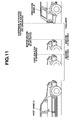
- Fig. 11 is a view showing operation start timing of these restraining devices 31, 32, 33 and 34.
- the programmed operation of each restraining device 31, 32, 33 or 34 has been explained with reference to the flowchart of Fig. 8.
- Fig. 11 shows the operation timing of these devices with respect to a collision of the host vehicle with the preceding vehicle.
- sensitivity adjusting section 42 adjusts the sensitivity of short distance radar system 11.
- knee bolster 31 When, based on the information signal from short distance radar system 11, it is judged that the time left until the predicted collision is 1.0 second, knee bolster 31 becomes operated. Due to operation of this knee bolster 31, the knee portion of a seat occupant is held and thus forward movement of the lower portion of the passenger is suppressed. Because the sensitivity of short distance radar system 11 has been adjusted, operation of knee bolster 31 is appropriately carried out in accordance with the precise vehicle collision prediction.
- motor driven retractor 32 When, based on the information signal from short distance radar system 11, it is judged that the time until the predicted collision is 0.5 second, motor driven retractor 32 becomes operated. With this, the seatbelt is slightly retracted to restrain an upper portion of the seat occupant. Since the sensitivity adjustment of short distance radar system 11 has been carried out already, operation of motor driven retractor 32 is appropriately carried out in accordance with the precise vehicle collision prediction.
- the sensitivity of short distance radar 11 is adjusted before encountering a collision against a preceding vehicle. That is, the sensitivity is adjusted in accordance with conditions of the host and preceding vehicles before the collision, and thus, the collision prediction ability of the device 100 is increased.
- the sensitivity of short distance radar system 11 is adjusted.
- the collision detection ability can be increased.
- the vehicle collision detecting ability is increased, a so-called mis-collision detection wherein prediction of vehicle collision is erroneously issued even when there is no possibility of such vehicle collision is suppressed or at least minimized.
- operation of the reversible restraining devices 31 and 32 and the non-reversible restraining devices 33 and 34 is much more precisely carried out.
- the radar systems 10 and 11 that are of a non-contact type are subjected to adjustment in sensitivity. Accordingly, by adjusting a radio wave, ultrasonic wave or light beam, a vehicle collision can be precisely predicted, and based on the precise prediction, operation of the reversible restraining devices 31 and 32 and non-reversible restraining devices 33 and 34 can be appropriately controlled.
- the signal receiving sensitivity of at least one of the radio wave, ultrasonic wave and light beam is adjusted. Accordingly, the sensitivity adjustment can be carried out without increasing a transmission power and without increasing electric power consumption.
- the signal transmission intensity of at least one of the radio wave, ultrasonic wave and light beam is carried out appropriately without being affected by surrounding noises.
- the sensitivity adjustment of short distance radar system 11 is carried out by varying the threshold value "Th2", which means an easiness with which the sensitivity of the system 11 is made. That is, such sensitivity adjustment is carried out without worrying about the hardware of long and short distance radar systems 10 and 11.
- the sensitivity adjustment of short distance radar system 11 is carried out when a vehicle collision is predicted based on the information signal from long distance radar system 10.
- the sensitivity of the accelerometer 20 may be adjusted when a vehicle collision is predicted based on the information from short distance radar system 11.
- Fig. 12 is a flowchart that shows a part of programmed operation steps executed by control unit 40 employed in the second embodiment 200 of the present invention. More specifically, the flowchart shows the detail of a modification of step ST17 of the flowchart of Fig. 6.
- this second embodiment 200 depending on whether a prediction of vehicle collision by long distance radar system 10 is present or not, the operation order of knee bolster 31 and motor driven retractor 32 is changed.
- step ST40 based on information signal from short distance radar system 11, judgment is carried out as to whether a vehicle collision has been predicted or not. If YES, that is, when the vehicle collision has been predicted, the operation flow goes to step ST41. At this step, operation timing deciding section 44 carries out judgment as to whether or not the vehicle collision has been predicted based on the information signal from long distance radar system (LDRS) 10. If YES, that is, when the vehicle collision has been predicted based on the information signal from long distance radar system 10, the operation flow goes to step ST42. At this step, operation timing deciding section 44 judges whether the predicted collision would occur within 1.5 second or not. If NO, the operation flow goes back to step ST18 of the above-mentioned flowchart of Fig. 6.
- LDRS long distance radar system
- step ST42 While, if YES at step ST42, that is, when it is judged that the predicted collision would occur within 1.5 second, the operation flow goes to step ST43 judging that knee bolster 31 should be operated. At this step, corresponding instruction signal is fed to knee bolster drive instruction section 45b for the operation of knee bolster 31.
- step ST44 operation timing deciding section 44 carries out judgment as to whether the predicted collision would occur within 1.0 second or not.
- step ST44 While, if YES at step ST44, that is, when it is judged that the vehicle collision would occur within 1.0 second, the operation flow goes to step ST45 judging that motor driven retractor 32 should be operated. At this step, corresponding instruction signal is fed to motor driven retractor drive instruction section 45a for the operation of the retractor 32.
- step ST41 While, if NO at step ST41, that is, when it is judged that the vehicle collision has not been predicted based on the information signal from long distance radar system (LDRS) 10, the operation flow goes to step ST49.
- operation timing deciding section 44 carries out judgment as to whether the predicted vehicle collision would occur within 1.0 second or not.
- step ST49 If NO at step ST49, the operation flow goes back to step ST18 of the flowchart of Fig. 6. While, if YES at step ST49, that is, when it is judged that the vehicle collision would occur within 1.0 second, the operation flow goes to step ST50 judging that motor driven retractor 32 should be operated. At this step, corresponding instruction signal is fed to motor driven retractor drive instruction section 45a for the operation of the retractor 32.
- step ST51 operation timing deciding section 44 carries out judgment as to whether the predicted collision would occur within 0.5 second or not. If NO, the operation flow goes back to step ST18 of the flowchart of Fig. 8. While, if YES, the operation flow goes to step ST52 judging that knee bolster 31 should be operated. At this step, corresponding instruction signal is fed to knee bolster drive instruction section 45b for the operation of knee bolster 31.
- knee bolster 31 and motor driven retractor 32 are varied. That is, when such prediction is present, knee bolster 31 is operated first, while, when such prediction is not present, motor driven retractor 32 is operated first. That is, when the vehicle collision prediction is high, restraining of the seat occupant is effected by knee bolster 31 at first and then by motor driven retractor 32. This brings about a reliable operation of knee bolster 31 for supporting the knee portion of the seat occupant before the collision.
- knee bolster 31 when operation of knee bolster 31 is made at first, the time until the real collision is increased which permits a reduction in operation speed of knee bolster 31. Due to reduction in this operation speed, operation of knee bolster 31 minimizes an uncomfortable feeling that would be applied to the seat occupant upon such operation.
- reversible restraining devices 31 and 32 and non-reversible restraining devices 33 and 34 are much more precisely controlled. Based on the precise prediction on a vehicle collision, these restraining devices 31, 32, 33 and 34 are appropriately controlled.
- the sensitivity adjustment can be carried out without increasing the transmission power and without increasing electric power consumption. Furthermore, the sensitivity adjustment can be carried out appropriately without being affected by surrounding noises.
- a passenger restraint device 300 of a third embodiment of the present invention will be described with reference to Fig. 13.
- each of long and short distance radar systems 10 and 11 employed in the third embodiment 300 emits a radio wave 10' or 11' scanning the forward zone at a predetermined cycle.
- collision prediction judgment section 41 detects the direction in which an obstacle (or preceding vehicle) is positioned.
- long distance radar system 10 detects the obstacle, the sensitivity of short distance radar system 11 for detecting the direction of the obstacle is increased.
- Fig. 14 is a flowchart that shows a part of programmed operation steps executed by control unit 40 employed in the third embodiment 300. More specifically, the flowchart shows the detail of a modification of step ST12 of the flowchart of Fig. 6.
- step ST60 based on the information signal from long distance radar system 10, judgment is carried out as to whether an obstacle in front of the host vehicle has been detected or not. If NO, the operation flow goes to step ST61. At this step, no sensitivity adjustment is carried out in short distance radar system 11. While, if at step ST 61 the sensitivity in a given direction has been kept increased, sensitivity adjusting section 42 returns the sensitivity of the system 11 to a lower level. Then, the operation flow goes to step ST64 which will be described hereinafter.
- step ST60 that is, when an obstacle has been detected by long distance radar system 10
- step ST62 judgment is carried out as to whether or not the scanning direction of short distance radar system 11 coincides with the direction in which the obstacle is located. If NO, the operation flow goes to step ST61 that has been described hereinabove.
- step ST63 While, if YES, that is, when the scanning direction of short distance radar system 11 coincides with the direction of the obstacle, the operation flow goes to step ST63.
- sensitive adjusting section 42 increases the sensitivity of that direction of short distance radar system 11.
- step ST64 short distance radar system (SDRS) 11 emits a radio wave against the obstacle for detecting the same.
- step ST65 scanning direction of short distance radar system 11 is changed throughout every given forward directions.
- step ST66 judgment is carried out as to whether the changing of scanning direction of the system 11 throughout the every given forward directions has finished or not. If NO, the operation flow goes back to step ST60. While, if YES, that is, when the changing of scanning direction throughout the given directions has finished, the operation flow goes back to step ST13 of the flowchart of Fig. 6.
- this third embodiment 300 when, based on the information signal from long distance radar system 10, the obstacle is detected, the sensitivity of short distance radar system 11 in the direction in which the obstacle is present is increased. Thus, the prediction of vehicle collision with the obstacle can have a higher precision particularly in such direction.
- the detection sensitivity of the system 11 in other direction in which the obstacle is not present is not increased, which lowers possibility of undesired mis-prediction. That is, as is easily known, to the direction in which such obstacle is not present, there is no need of increasing the detection sensitivity. Increasing the detection sensitivity in such unnecessary direction increases the possibility of mis-detection.
- the third embodiment 300 reversible restraining devices 31 and 32 and non-reversible restraining devices 33 and 34 are much more precisely controlled. Based on the precise prediction on a vehicle collision, these restraining devices 31, 32, 33 and 34 are appropriately controlled.
- the sensitivity adjustment can be carried out without increasing the transmission power and without increasing electric power consumption. Furthermore, the sensitivity adjustment can be carried out appropriately without being affected by surrounding noises.
- the sensitivity of only the direction in which a vehicle collision is predicted is adjusted higher than that of other direction. That is, increase in sensitivity is applied to only the direction in which the possibility of a vehicle collision is high, and thus, the vehicle collision prediction is precisely achieved.
- the detection sensitivity in a direction in which the possibility of a vehicle collision is low is not increased. Accordingly, mis-detection that would be induced by increasing the sensitivity in such direction is suppressed or at least minimized.
- vehicle collision prediction ability is much increased in this third embodiment 300, and thus, operation of reversible restraining devices 31 and 32 and non-reversible restraining devices 33 and 34 can be appropriately controlled.
- the following modification may be employed in this third embodiment 300. That is, the sensitivity in the direction in which a obstacle is present is kept unchanged, and the sensitivity in the other direction in which the obstacle is not present is lowered. Also, in this modification, similar advantages are obtained.
- the measures of the above-mentioned second embodiment 200 may be applied to the third embodiment 300. That is, for example, as is seen from the flowchart of Fig. 12, the operation timing of knee bolster 31 may be advanced. That is, like in the second embodiment 200, in case wherein the possibility of vehicle collision is high, restraining of the seat occupant is carried out fast. The reduction in operation speed of knee bolster 31, that would be provided by the advanced operation timing, reduces the uncomfortable feeling applied to the seat occupant.
- a passenger restraint device 400 of a fourth embodiment of the present invention will be described with reference to Figs. 15, 16 and 17.
- a contact type collision sensor 12 is employed in place of the above-mentioned short distance radar system 11.
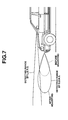
- Fig. 15 shows one contact type collision sensor 12 which comprises a support bar fixed to a front portion of the host vehicle and a sensor element 12a fixed to a leading end of the support bar.
- the sensor element 12a may be of a mechanical touch type, a vibration detecting type, a pressure detecting type or the like. Due to the nature of such type collision sensor 12, the collision detect sensitivity of the sensor 12 is increased with increase of distance between sensor element 12a and the front edge of the host vehicle.
- Fig. 16 shows a modification of the contact type collision sensor.
- the sensor element 12a is installed in a front bumper.
- the collision detect sensitivity of this modification can be adjusted by changing a fore-and-aft position of the bumper.
- Fig. 17 shows a flowchart that shows a part of programmed operation steps executed by a control unit 40 employed in the fourth embodiment 400 of the present invention. More specifically, in the fourth embodiment 400, the steps ST12, ST13, ST14 and ST17 of the flowchart of Fig. 6 are modified.
- step ST70 based on information signal from long distance radar system 10, operation timing deciding section 44 carries out judgment as to whether a vehicle collision has been predicted or not. If YES, that is, when it is judged that the vehicle collision has been predicted, the operation flow goes to step ST71.
- step ST74 the operation flow goes to step ST75.
- operation timing deciding section 44 carries out judgment as to whether the contact type collision sensor 12 has detected a contact of the sensor 12 with an obstacle. If NO, the operation flow goes to step ST18 of the flowchart of Fig. 6.
- step ST76 judging that cartridge activated retractor 34 should be operated.
- corresponding instruction signal is fed to cartridge activated retractor drive instruction section 45c for operation of the retractor 34.
- step ST77 operation timing deciding section 44 carries out as to whether a vehicle collision has been detected or not. That is, the section 44 judges whether the result issued from collision detection judgment section 43 represents occurrence of vehicle collision or not.
- step S77 If NO at step S77, that is, when it is judged that vehicle collision has not been detected, the operation flow goes back to step ST18 of the flowchart of Fig. 6. While, if YES, that is, when it is judged that the vehicle collision has been detected, the operation flow goes to step ST78 judging that air bag 33 should be operated. At this step, air bag 33 is operated. Thereafter, the operation flow goes to step ST18 of the flowchart of Fig. 6.
- step ST70 If NO at step ST70, that is, when it is judged that a vehicle collision has not been predicted, the operation flow goes to step ST79 and to ST80. These steps ST79 and ST80 are the same as those of the above-mentioned steps ST28 and ST29 of the first embodiment. Thereafter, the operation flow goes back to step ST18 of the flowchart of Fig. 6.
- a so-called contact detection judgment treatment (ST75) is carried out. Since collision sensor 12 is of a contact type, the sensor 12 is hardly affected by noises as compared with sensors of non-contactable type. Collision prediction judgment section 41 is configured to predict or detect a vehicle collision when an obstacle is brought into collision with the sensor 12. Thus, precise vehicle collision prediction is carried out in this fourth embodiment 400.
- cartridge activated retractor 34 which is the non-reversible restraining device, is instantly operated.
- the operation of such non-reversible restraining device 34 can be assuredly carried out.
- the restraining devices 31, 32, 33 and 34 are appropriately controlled.
- reversible restraining devices 31 and 32 and non-reversible restraining devices 33 and 34 are much more precisely controlled.
- sensor element 12a is projected or retracted with respect to the vehicle body.
- sensor element 12a is projected forward, the precise vehicle collision prediction is achieved much faster. This can induce an advanced operation of non-reversible restraining devices 33 and 34.
- a passenger restraint device 500 of a fifth embodiment of the present invention will be described with reference to Fig. 18.
- a long distance radar system 10 such as one used in the above-mentioned third embodiment 300 is used, and plurality of contact type collision sensors 12 arranged at laterally spaced positions of the front part of an associated motor vehicle.
- the collision sensors 12 have respective sensor elements 12a that are projectable forward by a given distance from the front part of the vehicle.
- long distance radar system 10 scans a predetermined forward zone at a predetermined cycle.
- collision prediction judgment section 41 detects the direction in which the obstacle is located.
- a sensor element 12a or sensor elements 12a of the contact type collision sensors 12 that are arranged in the direction in which the obstacle is present are subjected to the sensitivity adjustment. That is, only the sensor elements 12a are projected forward for increasing the sensitivity of the same, as shown in the drawing.
- the step for carrying out the sensitivity adjustment is substantially the same as the step ST 12 (see Fig. 6).
- the fifth embodiment 500 only the sensor element 12a or sensor elements 12a of the contact type collision sensors 12 that are arranged in the direction in which the obstacle is present are subjected to the sensitivity adjustment.
- the vehicle collision prediction carried out by the fifth embodiment 500 is much improved. That is, in the fifth embodiment 500, the sensor elements 12a other than the sensor elements 12a that are subjected to the sensitivity adjustment are left unchanged in the sensitivity. Thus, unnecessary and redundant high detection by such sensor elements 12a is avoided, which increases an assured prediction of the obstacle.
- prediction of vehicle collision made by the sensors 12 is much assured.
- a passenger restraint device 600 of a sixth embodiment of the present invention will be described with reference to Fig. 19.
- the sixth embodiment 600 is similar to the above-mentioned first embodiment 100. However, in the sixth embodiment 600, the treatment of step ST12 (see the flowchart of Fig. 6) is somewhat different. That is, in the sixth embodiment 600, the sensitivity of short distance radar system 11 is adjusted based on the higher one of a running speed of the host motor vehicle and a relative vehicle speed between the host motor vehicle and the preceding motor vehicle.
- Fig. 19 is a graph used for adjusting the detecting distance of short distance radar system 11 (or the sensitivity of the system 11) in accordance with the vehicle speed or relative vehicle speed.
- sensitivity adjusting section 42 of control unit adjusts the detecting distance of the radar system 11 to a minimum value "D1”
- the section 42 adjusts the detecting distance to a maximum value "D2”.
- the vehicle speed or relative vehicle speed is within the range from the value "C1" to the value "C2”
- the section 42 adjusts the detecting distance to a value that linearly varies from the value "D1" to the value "D2".
- the sensitivity of short distance radar system 11 is increased with increase of the vehicle speed or relative vehicle speed. This improves the prediction of a vehicle collision effected by the present invention.
- reversible restraining devices 31 and 32 and non-reversible restraining devices 33 and 34 are much more precisely controlled.
- the sensitivity adjustment can be carried out without increasing the transmission power and without increasing electric power consumption. Furthermore, the sensitivity adjustment can be carried out appropriately without being affected by surrounding noises.
- the sensitivity is adjusted based on a higher one of the running speed of the host motor vehicle and the relative vehicle speed between the host motor vehicle and the preceding motor vehicle. That is, the distance between the two vehicles can be assuredly detected even when such speed becomes high.
- mis-matching in operation of the restraining devices 31, 32, 33 and 34 is suppressed. That is, undesired situation wherein upon the time on which a vehicle collision is predicted, a remaining time until the vehicle collision is quite small is suppressed.
- the restraining devices 31, 32, 33 and 34 can be appropriately operated.
- the sensitivity may be adjusted based on the vehicle speed of the host motor vehicle. Furthermore, the sensitivity may be adjusted based on the relative vehicle speed between the two motor vehicles.
- an electric seat slide in place of the above-mentioned knee bolster 31 and motor driven retractor 32, an electric seat slide, an electric seat cushion angle adjuster, an electric seat back angle adjuster, an electric telescopic steering column adjuster, an electric power window, an electric sunroof controller and an electric interior pad may be used.
- an active headrest 35 (see Fig. 20) and an electric door trim 36 (see Fig. 21) may be used.
- These devices 35 and 36 are controlled by control unit 40 to respectively support or hold a head and a side portion of the seated occupant upon a vehicle collision, as shown.
- the actuation order of these devices 35 and 36 may be based on the actuation speed of the same, and on the degree of touch feeling applied to the seated occupant by the devices 35 and 36. If the order is based on the touch feeling, feeling of wrongness applied to the occupant is suppressed or at least minimized.
- the order is based on the actuation speed of the devices 35 and 36, much assured restriction is carried out.
- the order is based on the actuation speed of the devices 35 and 36.
- an electric actuator for powering the above-mentioned reversible and non-reversible type restricting devices 31, 32, 33, 34, 35 and 36, an electric actuator, a hydraulic actuator, a spring, a cartridge-activated actuator or the like may be used. Of course, combination of these actuators is also usable.
- long and short distance radar systems 10 and 11 and contact sensor 12 are used for detecting information on a vehicle collision.
- other means can be used so long as the means can detect such information.
- description is directed to the collision in which a host vehicle collides against a rear portion of a preceding vehicle.
- the concept of the present invention is also usable in a side vehicle collision, a head-on collision and a vehicle rolling.
- the means that detects or predicts a vehicle collision may be of a self-establishing type that establishes such function by itself.
- the means for detecting or predicting the vehicle collision may of a non-self-establishing type that needs an external assistance for establishing such function. That is, in the latter type, only information signals needed for detecting or predicting a vehicle collision are detected by the means and these information signals are led to a calculating circuit. In the circuit, various calculations are carried out for detecting or predicting the vehicle collision.
Applications Claiming Priority (2)
| Application Number | Priority Date | Filing Date | Title |
|---|---|---|---|
| JP2003366269A JP4449409B2 (ja) | 2003-10-27 | 2003-10-27 | 車両用乗員保護装置 |
| JP2003366269 | 2003-10-27 |
Publications (2)
| Publication Number | Publication Date |
|---|---|
| EP1527959A1 true EP1527959A1 (fr) | 2005-05-04 |
| EP1527959B1 EP1527959B1 (fr) | 2011-01-05 |
Family
ID=34420102
Family Applications (1)
| Application Number | Title | Priority Date | Filing Date |
|---|---|---|---|
| EP04024966A Expired - Fee Related EP1527959B1 (fr) | 2003-10-27 | 2004-10-20 | Dispositif de retenue des occupants d'un véhicule |
Country Status (5)
| Country | Link |
|---|---|
| US (1) | US7441624B2 (fr) |
| EP (1) | EP1527959B1 (fr) |
| JP (1) | JP4449409B2 (fr) |
| CN (1) | CN100344479C (fr) |
| DE (1) | DE602004030870D1 (fr) |
Cited By (5)
| Publication number | Priority date | Publication date | Assignee | Title |
|---|---|---|---|---|
| WO2008034672A1 (fr) * | 2006-09-21 | 2008-03-27 | Robert Bosch Gmbh | Système d'aide à la conduite avec une préparation des données adaptée à la fonction concernée |
| WO2010136882A1 (fr) * | 2009-05-29 | 2010-12-02 | Toyota Jidosha Kabushiki Kaisha | Appareil de commande de véhicule, véhicule, et procédé de commande de véhicule |
| WO2011042182A1 (fr) * | 2009-10-08 | 2011-04-14 | Daimler Ag | Véhicule à propulsion électrique et composants de sécurité réversibles |
| WO2014198389A1 (fr) * | 2013-06-11 | 2014-12-18 | Audi Ag | Système de sécurité pour un véhicule automobile, véhicule automobile associé et procédé servant à commander un système de sécurité pour un véhicule automobile |
| EP3945001A1 (fr) * | 2020-07-27 | 2022-02-02 | Hyundai Motor Company | Dispositif et procédé de commande de conduite autonome |
Families Citing this family (36)
| Publication number | Priority date | Publication date | Assignee | Title |
|---|---|---|---|---|
| JP4321314B2 (ja) * | 2003-06-25 | 2009-08-26 | トヨタ自動車株式会社 | 乗員保護装置 |
| DE10332024A1 (de) * | 2003-07-15 | 2005-02-17 | Daimlerchrysler Ag | Verfahren zur Ansteuerung eines reversiblen Gurtstraffers in einem Kraftfahrzeug |
| JP2005173929A (ja) * | 2003-12-10 | 2005-06-30 | Denso Corp | 覚醒度判定装置 |
| US7484118B2 (en) * | 2003-12-16 | 2009-01-27 | International Business Machines Corporation | Multi nodal computer system and method for handling check stops in the multi nodal computer system |
| JP2005212504A (ja) * | 2004-01-27 | 2005-08-11 | Takata Corp | 車両用乗員保護装置 |
| US20090128515A1 (en) * | 2007-11-02 | 2009-05-21 | Bytheway Jared G | Proximity sensing by increasing gain in touchpad circuitry and increasing distance between sensor electrodes and a sense electrode |
| US8095276B2 (en) * | 2008-10-15 | 2012-01-10 | Autoliv Asp, Inc. | Sensor system including a confirmation sensor for detecting an impending collision |
| JP4877364B2 (ja) | 2009-07-10 | 2012-02-15 | トヨタ自動車株式会社 | 物体検出装置 |
| JP2011037308A (ja) * | 2009-08-06 | 2011-02-24 | Aisin Seiki Co Ltd | 車両用乗員保護システム |
| DE102010031261A1 (de) * | 2010-07-12 | 2012-01-12 | Robert Bosch Gmbh | Verfahren und Vorrichtung zum Schutz eines Fahrzeuginsassen bei einem Aufprall |
| EP2720211B1 (fr) | 2011-06-09 | 2016-08-10 | Toyota Jidosha Kabushiki Kaisha | Dispositif de détection d'autres véhicules et procédé de détection d'autres véhicules |
| DE102013017957A1 (de) * | 2013-10-29 | 2015-04-30 | Daimler Ag | Verfahren zur Ansteuerung zumindest eines in einem Fahrzeugsitz angeordneten Schutzelementes |
| EP2883756B1 (fr) * | 2013-12-12 | 2019-11-06 | Volvo Car Corporation | Système de sécurité et procédé de fonctionnement pour système de sécurité d'un véhicule |
| US9437111B2 (en) * | 2014-05-30 | 2016-09-06 | Ford Global Technologies, Llc | Boundary detection system |
| JP6519451B2 (ja) * | 2015-11-05 | 2019-05-29 | トヨタ自動車株式会社 | エアバッグ装置 |
| CN105539354B (zh) * | 2016-01-20 | 2018-01-05 | 吉林大学 | 一种基于形状记忆合金的缓冲吸能式安全带预紧控制方法 |
| DE102016201805A1 (de) * | 2016-02-05 | 2017-08-10 | Robert Bosch Gmbh | Verfahren und Steuergerät zum Einstellen eines Ansteuersignals zum Ansteuern mindestens einer Sicherheitseinrichtung eines Fahrzeugs |
| CN108237997B (zh) * | 2016-12-27 | 2020-08-07 | 比亚迪股份有限公司 | 自动导引搬运叉车及其保护系统和保护方法 |
| JP6753324B2 (ja) * | 2017-01-25 | 2020-09-09 | トヨタ自動車株式会社 | 車両用乗員保護装置及び車両用乗員保護方法 |
| EP3379222B1 (fr) | 2017-03-22 | 2020-12-30 | Methode Electronics Malta Ltd. | Ensemble de capteur à base magnétoélastique |
| KR102028398B1 (ko) * | 2017-05-17 | 2019-11-04 | (주)에스더블유엠 | 주행 중 장애물 정보를 제공하는 방법 및 장치 |
| DE18907724T1 (de) | 2018-02-27 | 2021-03-25 | Methode Electronics, Inc. | Schleppsysteme und Verfahren mit Verwendung von Magnetfeldmessung |
| US11491832B2 (en) | 2018-02-27 | 2022-11-08 | Methode Electronics, Inc. | Towing systems and methods using magnetic field sensing |
| US11221262B2 (en) | 2018-02-27 | 2022-01-11 | Methode Electronics, Inc. | Towing systems and methods using magnetic field sensing |
| US11014417B2 (en) | 2018-02-27 | 2021-05-25 | Methode Electronics, Inc. | Towing systems and methods using magnetic field sensing |
| US11135882B2 (en) | 2018-02-27 | 2021-10-05 | Methode Electronics, Inc. | Towing systems and methods using magnetic field sensing |
| US11084342B2 (en) | 2018-02-27 | 2021-08-10 | Methode Electronics, Inc. | Towing systems and methods using magnetic field sensing |
| US10457208B1 (en) * | 2018-05-08 | 2019-10-29 | Freedman Seating Company | Vehicle passenger sensing and reporting system |
| US11318910B2 (en) | 2018-05-08 | 2022-05-03 | Freedman Seating Company | Vehicle passenger sensing and reporting system |
| CN109435886B (zh) * | 2018-12-05 | 2021-02-23 | 广西农业职业技术学院 | 一种汽车安全驾驶辅助检测方法 |
| US20200209887A1 (en) * | 2018-12-28 | 2020-07-02 | Robert Bosch Gmbh | System and method for adjusting control of an autonomous vehicle using crowd-source data |
| US11084445B2 (en) * | 2019-02-06 | 2021-08-10 | Ford Global Technologies, Llc | Energy-absorbing knee bolster |
| KR20210003343A (ko) * | 2019-07-01 | 2021-01-12 | 현대자동차주식회사 | 차량의 안전 장비 제어 장치 및 방법 |
| US11427146B2 (en) * | 2019-07-10 | 2022-08-30 | Pony Ai Inc. | Collision protection |
| JP7368127B2 (ja) * | 2019-07-12 | 2023-10-24 | 株式会社ダイセル | 乗員保護装置 |
| US11884228B2 (en) * | 2022-05-12 | 2024-01-30 | Ford Global Technologies, Llc | Airbag on law-enforcement vehicle partition |
Citations (5)
| Publication number | Priority date | Publication date | Assignee | Title |
|---|---|---|---|---|
| JPH06286581A (ja) | 1993-03-31 | 1994-10-11 | Nissan Motor Co Ltd | 乗物用シートベルト装置 |
| DE19818586C1 (de) | 1998-04-25 | 1999-09-30 | Daimler Chrysler Ag | Schutzvorrichtung für ein Kraftfahrzeug |
| US6271747B1 (en) * | 1998-04-18 | 2001-08-07 | Daimlerchrysler Ag | Method for adjusting the trigger threshold of vehicle occupant protection devices |
| JP2003175797A (ja) | 2001-12-11 | 2003-06-24 | Toyota Motor Corp | 乗員保護システム |
| US20030149530A1 (en) | 2002-02-01 | 2003-08-07 | Ford Global Technologies, Inc. | Collision warning and safety countermeasure system |
Family Cites Families (19)
| Publication number | Priority date | Publication date | Assignee | Title |
|---|---|---|---|---|
| WO1990003289A1 (fr) * | 1988-09-17 | 1990-04-05 | Robert Bosch Gmbh | Appareil et procede de declenchement d'un systeme de protection pour les occupants d'un vehicule |
| DE3924507A1 (de) * | 1989-02-18 | 1990-08-23 | Bosch Gmbh Robert | Verfahren zur ausloesung von rueckhaltemitteln |
| US7284769B2 (en) * | 1995-06-07 | 2007-10-23 | Automotive Technologies International, Inc. | Method and apparatus for sensing a vehicle crash |
| US6557889B2 (en) * | 1991-07-09 | 2003-05-06 | Automotive Technologies International Inc. | Crush velocity sensing vehicle crash sensor |
| DE4212421A1 (de) * | 1992-04-14 | 1993-10-28 | Bosch Gmbh Robert | Verfahren und Einrichtung zum Schutz von Fahrzeuginsassen |
| DE4309827C2 (de) * | 1993-03-26 | 1995-12-14 | Daimler Benz Ag | Auslösevorrichtung für eine Sicherheitseinrichtung in einem Fahrzeug, insbesondere für einen Seiten-Airbag |
| JP3333813B2 (ja) * | 1996-11-20 | 2002-10-15 | トヨタ自動車株式会社 | 乗員保護装置の起動制御装置 |
| JP3063731B2 (ja) * | 1998-04-02 | 2000-07-12 | トヨタ自動車株式会社 | 乗員保護装置の起動制御装置 |
| US6268803B1 (en) * | 1998-08-06 | 2001-07-31 | Altra Technologies Incorporated | System and method of avoiding collisions |
| JP3300668B2 (ja) * | 1998-08-27 | 2002-07-08 | トヨタ自動車株式会社 | 衝突形態判別装置及び乗員保護装置の起動制御装置 |
| DE19854380A1 (de) * | 1998-11-25 | 2000-05-31 | Bayerische Motoren Werke Ag | Verfahren zum Erkennen der Schwere eines Fahrzeugzusammenstoßes |
| US6295495B1 (en) * | 2001-04-24 | 2001-09-25 | Ford Global Technologies, Inc. | Method for multi-directional anticipatory arming of vehicle restraints |
| JP3695351B2 (ja) * | 2001-05-14 | 2005-09-14 | トヨタ自動車株式会社 | 乗員保護装置の起動装置 |
| JP4023228B2 (ja) * | 2002-06-19 | 2007-12-19 | 日産自動車株式会社 | 車載用障害物検知装置 |
| GB2410111C (en) * | 2002-07-02 | 2006-06-12 | Autoliv Dev | A triggering unit |
| DE10244095A1 (de) * | 2002-09-23 | 2004-04-01 | Robert Bosch Gmbh | Anordnung zum Ansteuern von Rückhaltemitteln |
| JP4082177B2 (ja) * | 2002-10-30 | 2008-04-30 | トヨタ自動車株式会社 | 車両用安全装置 |
| JP3959718B2 (ja) * | 2002-12-03 | 2007-08-15 | 株式会社デンソー | 車両用歩行者衝突検出装置 |
| US7236865B2 (en) * | 2004-09-08 | 2007-06-26 | Ford Global Technologies, Llc | Active adaptation of vehicle restraints for enhanced performance robustness |
-
2003
- 2003-10-27 JP JP2003366269A patent/JP4449409B2/ja not_active Expired - Fee Related
-
2004
- 2004-10-20 EP EP04024966A patent/EP1527959B1/fr not_active Expired - Fee Related
- 2004-10-20 DE DE602004030870T patent/DE602004030870D1/de active Active
- 2004-10-26 US US10/972,691 patent/US7441624B2/en not_active Expired - Fee Related
- 2004-10-27 CN CNB2004100861280A patent/CN100344479C/zh not_active Expired - Fee Related
Patent Citations (5)
| Publication number | Priority date | Publication date | Assignee | Title |
|---|---|---|---|---|
| JPH06286581A (ja) | 1993-03-31 | 1994-10-11 | Nissan Motor Co Ltd | 乗物用シートベルト装置 |
| US6271747B1 (en) * | 1998-04-18 | 2001-08-07 | Daimlerchrysler Ag | Method for adjusting the trigger threshold of vehicle occupant protection devices |
| DE19818586C1 (de) | 1998-04-25 | 1999-09-30 | Daimler Chrysler Ag | Schutzvorrichtung für ein Kraftfahrzeug |
| JP2003175797A (ja) | 2001-12-11 | 2003-06-24 | Toyota Motor Corp | 乗員保護システム |
| US20030149530A1 (en) | 2002-02-01 | 2003-08-07 | Ford Global Technologies, Inc. | Collision warning and safety countermeasure system |
Cited By (7)
| Publication number | Priority date | Publication date | Assignee | Title |
|---|---|---|---|---|
| WO2008034672A1 (fr) * | 2006-09-21 | 2008-03-27 | Robert Bosch Gmbh | Système d'aide à la conduite avec une préparation des données adaptée à la fonction concernée |
| WO2010136882A1 (fr) * | 2009-05-29 | 2010-12-02 | Toyota Jidosha Kabushiki Kaisha | Appareil de commande de véhicule, véhicule, et procédé de commande de véhicule |
| US8725403B2 (en) | 2009-05-29 | 2014-05-13 | Toyota Jidosha Kabushiki Kaisha | Vehicle control apparatus, vehicle, and vehicle control method |
| WO2011042182A1 (fr) * | 2009-10-08 | 2011-04-14 | Daimler Ag | Véhicule à propulsion électrique et composants de sécurité réversibles |
| WO2014198389A1 (fr) * | 2013-06-11 | 2014-12-18 | Audi Ag | Système de sécurité pour un véhicule automobile, véhicule automobile associé et procédé servant à commander un système de sécurité pour un véhicule automobile |
| US9718426B2 (en) | 2013-06-11 | 2017-08-01 | Audi Ag | Safety system for a motor vehicle, associated motor vehicle, and method for controlling a safety system for a motor vehicle |
| EP3945001A1 (fr) * | 2020-07-27 | 2022-02-02 | Hyundai Motor Company | Dispositif et procédé de commande de conduite autonome |
Also Published As
| Publication number | Publication date |
|---|---|
| DE602004030870D1 (de) | 2011-02-17 |
| US7441624B2 (en) | 2008-10-28 |
| JP4449409B2 (ja) | 2010-04-14 |
| CN1611390A (zh) | 2005-05-04 |
| EP1527959B1 (fr) | 2011-01-05 |
| CN100344479C (zh) | 2007-10-24 |
| US20050087381A1 (en) | 2005-04-28 |
| JP2005126006A (ja) | 2005-05-19 |
Similar Documents
| Publication | Publication Date | Title |
|---|---|---|
| EP1527959A1 (fr) | Dispositif de retenue des occupants d'un véhicule | |
| KR100873827B1 (ko) | 차량의 적어도 하나의 파라미터를 조작하기 위한 방법 및 장치 | |
| US8463500B2 (en) | Method for operating a pre-crash sensing system to deploy airbags using inflation control | |
| US7873473B2 (en) | Motor vehicle having a preventive protection system | |
| EP1456065B1 (fr) | Dispositif a ceinture de securite et procede de commande d'une ceinture de securite | |
| US9663052B2 (en) | Method for operating a pre-crash sensing system to deploy airbags using confidence factors prior to collision | |
| US7686340B2 (en) | Occupant restraint system and method for restraining occupant in seat of vehicle | |
| US5748477A (en) | Vehicle collision control system | |
| US6343810B1 (en) | Side impact airbag system with anticipatory sensor | |
| US6915196B2 (en) | Method for operating a vehicle crash safety system in a vehicle having a pre-crash sensing system and countermeasure systems | |
| US7712776B2 (en) | Method and control system for predictive deployment of side-impact restraints | |
| EP3309018B1 (fr) | Dispositif de retenue d'occupants pour véhicule | |
| EP1329366B1 (fr) | Système et methode de protection d'un passager d'un véhicule | |
| JP4591750B2 (ja) | 車両の乗員保護装置 | |
| US7380632B2 (en) | Safety system for operating at least one electrically actuated locking apparatus of a door of a motor vehicle | |
| US20050187685A1 (en) | Occupant restraint system | |
| US8851515B2 (en) | Method and device for protecting a vehicle occupant in a vehicle seat of a vehicle | |
| US6260880B1 (en) | Vehicle travel safety device | |
| US7204334B2 (en) | Occupant restraint system | |
| JP4848678B2 (ja) | 車両の制御装置 | |
| JP3562208B2 (ja) | 助手席乗員保護装置 | |
| JP2005126001A (ja) | 車両用乗員保護装置 |
Legal Events
| Date | Code | Title | Description |
|---|---|---|---|
| PUAI | Public reference made under article 153(3) epc to a published international application that has entered the european phase |
Free format text: ORIGINAL CODE: 0009012 |
|
| 17P | Request for examination filed |
Effective date: 20041021 |
|
| AK | Designated contracting states |
Kind code of ref document: A1 Designated state(s): AT BE BG CH CY CZ DE DK EE ES FI FR GB GR HU IE IT LI LU MC NL PL PT RO SE SI SK TR |
|
| AX | Request for extension of the european patent |
Extension state: AL HR LT LV MK |
|
| AKX | Designation fees paid |
Designated state(s): DE FR GB |
|
| 17Q | First examination report despatched |
Effective date: 20051129 |
|
| 17Q | First examination report despatched |
Effective date: 20051129 |
|
| APBN | Date of receipt of notice of appeal recorded |
Free format text: ORIGINAL CODE: EPIDOSNNOA2E |
|
| APBR | Date of receipt of statement of grounds of appeal recorded |
Free format text: ORIGINAL CODE: EPIDOSNNOA3E |
|
| APAF | Appeal reference modified |
Free format text: ORIGINAL CODE: EPIDOSCREFNE |
|
| APBT | Appeal procedure closed |
Free format text: ORIGINAL CODE: EPIDOSNNOA9E |
|
| GRAP | Despatch of communication of intention to grant a patent |
Free format text: ORIGINAL CODE: EPIDOSNIGR1 |
|
| GRAS | Grant fee paid |
Free format text: ORIGINAL CODE: EPIDOSNIGR3 |
|
| GRAA | (expected) grant |
Free format text: ORIGINAL CODE: 0009210 |
|
| AK | Designated contracting states |
Kind code of ref document: B1 Designated state(s): DE FR GB |
|
| REG | Reference to a national code |
Ref country code: GB Ref legal event code: FG4D |
|
| REF | Corresponds to: |
Ref document number: 602004030870 Country of ref document: DE Date of ref document: 20110217 Kind code of ref document: P |
|
| REG | Reference to a national code |
Ref country code: DE Ref legal event code: R096 Ref document number: 602004030870 Country of ref document: DE Effective date: 20110217 |
|
| PLBE | No opposition filed within time limit |
Free format text: ORIGINAL CODE: 0009261 |
|
| STAA | Information on the status of an ep patent application or granted ep patent |
Free format text: STATUS: NO OPPOSITION FILED WITHIN TIME LIMIT |
|
| 26N | No opposition filed |
Effective date: 20111006 |
|
| REG | Reference to a national code |
Ref country code: DE Ref legal event code: R097 Ref document number: 602004030870 Country of ref document: DE Effective date: 20111006 |
|
| REG | Reference to a national code |
Ref country code: FR Ref legal event code: PLFP Year of fee payment: 13 |
|
| REG | Reference to a national code |
Ref country code: FR Ref legal event code: PLFP Year of fee payment: 14 |
|
| REG | Reference to a national code |
Ref country code: FR Ref legal event code: PLFP Year of fee payment: 15 |
|
| PGFP | Annual fee paid to national office [announced via postgrant information from national office to epo] |
Ref country code: FR Payment date: 20180913 Year of fee payment: 15 |
|
| PGFP | Annual fee paid to national office [announced via postgrant information from national office to epo] |
Ref country code: DE Payment date: 20181009 Year of fee payment: 15 |
|
| PGFP | Annual fee paid to national office [announced via postgrant information from national office to epo] |
Ref country code: GB Payment date: 20181017 Year of fee payment: 15 |
|
| REG | Reference to a national code |
Ref country code: DE Ref legal event code: R119 Ref document number: 602004030870 Country of ref document: DE |
|
| PG25 | Lapsed in a contracting state [announced via postgrant information from national office to epo] |
Ref country code: DE Free format text: LAPSE BECAUSE OF NON-PAYMENT OF DUE FEES Effective date: 20200501 |
|
| GBPC | Gb: european patent ceased through non-payment of renewal fee |
Effective date: 20191020 |
|
| PG25 | Lapsed in a contracting state [announced via postgrant information from national office to epo] |
Ref country code: GB Free format text: LAPSE BECAUSE OF NON-PAYMENT OF DUE FEES Effective date: 20191020 Ref country code: FR Free format text: LAPSE BECAUSE OF NON-PAYMENT OF DUE FEES Effective date: 20191031 |