EP1527742B1 - Verschlussvorrichtung für Pedikelschrauben zur Fixierung von elastischen Stabelementen - Google Patents
Verschlussvorrichtung für Pedikelschrauben zur Fixierung von elastischen Stabelementen Download PDFInfo
- Publication number
- EP1527742B1 EP1527742B1 EP03405786A EP03405786A EP1527742B1 EP 1527742 B1 EP1527742 B1 EP 1527742B1 EP 03405786 A EP03405786 A EP 03405786A EP 03405786 A EP03405786 A EP 03405786A EP 1527742 B1 EP1527742 B1 EP 1527742B1
- Authority
- EP
- European Patent Office
- Prior art keywords
- pedicle screw
- closure cap
- closure
- engagement
- screw according
- Prior art date
- Legal status (The legal status is an assumption and is not a legal conclusion. Google has not performed a legal analysis and makes no representation as to the accuracy of the status listed.)
- Expired - Lifetime
Links
- 238000003780 insertion Methods 0.000 claims description 4
- 230000037431 insertion Effects 0.000 claims description 4
- 229920002635 polyurethane Polymers 0.000 claims description 2
- 239000004814 polyurethane Substances 0.000 claims description 2
- 208000020401 Depressive disease Diseases 0.000 claims 3
- 230000000903 blocking effect Effects 0.000 claims 1
- 230000002093 peripheral effect Effects 0.000 claims 1
- 230000003019 stabilising effect Effects 0.000 claims 1
- 229920002994 synthetic fiber Polymers 0.000 claims 1
- 230000000087 stabilizing effect Effects 0.000 abstract description 4
- 239000003381 stabilizer Substances 0.000 abstract 1
- 238000001356 surgical procedure Methods 0.000 description 4
- 230000005540 biological transmission Effects 0.000 description 3
- 238000004873 anchoring Methods 0.000 description 2
- 238000010521 absorption reaction Methods 0.000 description 1
- 230000006835 compression Effects 0.000 description 1
- 238000007906 compression Methods 0.000 description 1
- 230000001419 dependent effect Effects 0.000 description 1
- 238000011161 development Methods 0.000 description 1
- 230000018109 developmental process Effects 0.000 description 1
- 238000001746 injection moulding Methods 0.000 description 1
- 230000003993 interaction Effects 0.000 description 1
- 230000013011 mating Effects 0.000 description 1
- 229920003023 plastic Polymers 0.000 description 1
- 239000004033 plastic Substances 0.000 description 1
Images


Classifications
-
- A—HUMAN NECESSITIES
- A61—MEDICAL OR VETERINARY SCIENCE; HYGIENE
- A61B—DIAGNOSIS; SURGERY; IDENTIFICATION
- A61B17/00—Surgical instruments, devices or methods
- A61B17/56—Surgical instruments or methods for treatment of bones or joints; Devices specially adapted therefor
- A61B17/58—Surgical instruments or methods for treatment of bones or joints; Devices specially adapted therefor for osteosynthesis, e.g. bone plates, screws or setting implements
- A61B17/68—Internal fixation devices, including fasteners and spinal fixators, even if a part thereof projects from the skin
- A61B17/70—Spinal positioners or stabilisers, e.g. stabilisers comprising fluid filler in an implant
- A61B17/7001—Screws or hooks combined with longitudinal elements which do not contact vertebrae
- A61B17/7002—Longitudinal elements, e.g. rods
- A61B17/7004—Longitudinal elements, e.g. rods with a cross-section which varies along its length
- A61B17/7005—Parts of the longitudinal elements, e.g. their ends, being specially adapted to fit in the screw or hook heads
-
- A—HUMAN NECESSITIES
- A61—MEDICAL OR VETERINARY SCIENCE; HYGIENE
- A61B—DIAGNOSIS; SURGERY; IDENTIFICATION
- A61B17/00—Surgical instruments, devices or methods
- A61B17/56—Surgical instruments or methods for treatment of bones or joints; Devices specially adapted therefor
- A61B17/58—Surgical instruments or methods for treatment of bones or joints; Devices specially adapted therefor for osteosynthesis, e.g. bone plates, screws or setting implements
- A61B17/68—Internal fixation devices, including fasteners and spinal fixators, even if a part thereof projects from the skin
- A61B17/70—Spinal positioners or stabilisers, e.g. stabilisers comprising fluid filler in an implant
- A61B17/7001—Screws or hooks combined with longitudinal elements which do not contact vertebrae
- A61B17/7032—Screws or hooks with U-shaped head or back through which longitudinal rods pass
-
- A—HUMAN NECESSITIES
- A61—MEDICAL OR VETERINARY SCIENCE; HYGIENE
- A61B—DIAGNOSIS; SURGERY; IDENTIFICATION
- A61B17/00—Surgical instruments, devices or methods
- A61B17/56—Surgical instruments or methods for treatment of bones or joints; Devices specially adapted therefor
- A61B17/58—Surgical instruments or methods for treatment of bones or joints; Devices specially adapted therefor for osteosynthesis, e.g. bone plates, screws or setting implements
- A61B17/68—Internal fixation devices, including fasteners and spinal fixators, even if a part thereof projects from the skin
- A61B17/70—Spinal positioners or stabilisers, e.g. stabilisers comprising fluid filler in an implant
- A61B17/7001—Screws or hooks combined with longitudinal elements which do not contact vertebrae
- A61B17/7002—Longitudinal elements, e.g. rods
- A61B17/7019—Longitudinal elements having flexible parts, or parts connected together, such that after implantation the elements can move relative to each other
- A61B17/7031—Longitudinal elements having flexible parts, or parts connected together, such that after implantation the elements can move relative to each other made wholly or partly of flexible material
Definitions
- US-A-5,496,321 describes a pedicle screw with an anchoring means.
- this product has the disadvantage that the anchoring means must be inserted in the direction of the rod in the screw head, which can lead to considerable difficulties at small radii of curvature of the rod under operating conditions.
- US-A1-2003 / 0004511 describes a pedicle screw system whose receiving legs for a rod are connected to a hinge. After receiving the rod, the receiving legs are provided with a cap or a closure bracket, which squeeze the legs and hold the rod. To attach the cap or -bügel the legs of the head of the pedicle screw must be compressed, and at the same time the closure piece has to be inserted or rotated in the rod direction or the lock strap are hung, which is not only considerable skill of the surgeon, but depending on the version requires a special instrument.
- DE 199 51 145 A1 discloses an osteosynthesis device with a pedicle screw, with a groove having a clevis and mounted in the groove of the clevis correction rod, the base of the groove of the clevis is provided with a plurality of mutually parallel notches and the correction rod by means of a detent cover the pedicle screw is fixed.
- the present invention is therefore an object of the invention to provide a fastening system for stabilizing spinal columns consisting of an elastic rod and a pedicle screw with a closure device available, in which the power transmission from the rod to the screw on the open side is ensured and is prevented the staff backwards can slip out, and allows a safe and rapid closure of the recording of the rod in the pedicle screw to hold this in it.
- the closure device must be quickly disassembled again.
- closure cap which performs the function of a crosspiece which engages the rod in an existing groove structure and the forces thus absorbed in the longitudinal direction of the rod on the also grooved edges of the open receiving the pedicle screws transfers.
- closure device has a latching means (e.g., two hooks).
- the cap must be elastically movable so that it locks itself when inserting into the receptacle of the pedicle screw (hooking).
- appropriate means must be available where a corresponding instrument, preferably a universal instrument, can intervene.
- the subject of the present invention is therefore the fastening system as defined in claim 1.
- the pedicle screw with the closure device according to the invention is useful for the quick and secure closure and connection of an elastic rod member with a pedicle screw with a simultaneous transmission of force from the posterior rod side to the flanks of the pedicle screw.
- the closure cap provided for the closure device is expediently made of a biocompatible plastic, preferably polyurethane of the quality "medical grade", which can be processed by injection molding.
- the hooks provided on the cap snap into the appropriate recesses in the legs of the closure device on the head of the pedicle screws automatically, as soon as they are in the correct position. Further, means are provided which allow for easy removal of these closure devices, should this be required during the current or a later operation.
- a kinematic reversal Hooking and indenting is also possible and is intended to be encompassed by the definition of the present invention, although the geometry of the recesses must be adjusted, which, however, does not present an intractable problem to a person skilled in the art.
- At least one, preferably two, provided in the receiving recess latching projection serves to pre-fix the rod member in the receiving element before the cap is inserted, the rod element can be held both partially and completely positively in the receiving element, such that for correcting the position easy removal and Restoring the rod element during an operation is possible.
- both the rod element and the receiving recess have a mating groove / rib structure in the transverse direction to the rod element.
- An interaction of the latching projection or the latching projections with the mentioned positive-locking structure allows a pre-fixing in the longitudinal and transverse direction to the rod element.
- the groove structure in the interior of the receiving recess is preferably extended to the ends of its legs.
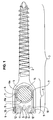
- FIG. 1 shows a typical embodiment of a closure device 1 according to the invention and, together with a threaded part 2, forms a pedicle screw 3, the closure device representing its head.
- the two-leg receiving element 4 with its U-shaped receiving recess 6 serves to receive a resilient rod member 14, wherein a latching projection 7 is a prefixing of the rod member 14, such that the rod member, if necessary, during surgery easily from a pedicle screw implanted on a vertebra can be removed again.
- the slight latching is determined by the elasticity of the rod element and / or the U-shaped retaining recess of the retaining element.
- the rod member 14, the receiving recess 6 and the retaining recess 8 may have a matching structure, for. B.
- the closure cap 5 is inserted into the receiving element 4.
- an adapted instrument such as a universal screwdriver, on which the closure cap is placed over the recess 13 and the cap can be used in the correct position accurately in the receiving recess under automatic latching.
- another instrument eg universal pliers, having the engagement projections for insertion into the recesses 12.
- the cap has latching elements (hooks) 9 on both sides, which serve to lock the closure cap in the region of the latching recesses 10. If the closure cap 5 in turn is to be removed from the receiving element 1, it is removed by means of said universal tongs.
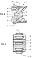
- Fig. 2 shows a sectional view of the closure cap of the closure device according to the invention shown in Fig. 1.
- the reference numerals correspond to the meanings given for FIG.
- the resilient deformation regions 15 are shown, which allow compression with said special tool in the direction of the arrows of the cap in the upper part, such that the mutual distance of the latching elements (hook) is reduced, allowing automatic engagement and also removal of the cap caused by disengagement from the receiving recess.
- Fig. 3 is a top view of the closure cap, the meaning of the reference numerals again corresponding to the above definitions.
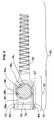
- FIG. 4 shows an alternative embodiment of a closure device 101 according to the invention and forms a pedicle screw 103 together with a threaded part 102.
- the receiving element 104 with its U-shaped receiving recess 106 serves to receive an elastic rod element 114, wherein a latching projection 107 serves to pre-fix the rod element 114 is used, so that the rod element can be easily removed during surgery from a pedicle screw implanted on a vertebra, if necessary.
- the rod member 114, the receiving recess 106 and the retaining recess 108 may also have here a matching structure, such as ribs or grooves 106a, 108a, preferably in the transverse direction.
- the closure cap 105 is inserted into the receiving element 104.
- the closure cap has hooks or latching elements 109 on both sides, which serve to deform the closure cap in the region of the latching recesses for latching into the latching recesses 110 of the receiving element 101.
- a bulge 116 supports in the locked state, the pressure on the hooks 109 and thus the tightness of the cap.
- FIG. 5 shows a sectional drawing of the closure cap of the closure device according to the invention shown in FIG. 4.
- the reference numerals correspond to the meanings given for FIG. 4.
- Fig. 6 is a top view of the closure cap, the meaning of the reference numerals again corresponding to the above definitions.
- FIG. 7 shows a sectional drawing of an alternative closure cap for a closure device according to the invention.
- the reference numerals have the following meanings: 205 the closure cap; 208, the holding recess; 208a ribs / grooves and 209 the hooks.
- 220 means an S-loop with a blind hole for insertion of a screwdriver, wherein a rotational movement causes a movement of the hooks 209 and thus a release of the closure cap.
- FIG. 8 is a top view of the alternative closure cap of FIG. 7, the meaning of the reference numerals again corresponding to the above definitions.
Landscapes
- Health & Medical Sciences (AREA)
- Orthopedic Medicine & Surgery (AREA)
- Life Sciences & Earth Sciences (AREA)
- Neurology (AREA)
- Surgery (AREA)
- Heart & Thoracic Surgery (AREA)
- General Health & Medical Sciences (AREA)
- Biomedical Technology (AREA)
- Nuclear Medicine, Radiotherapy & Molecular Imaging (AREA)
- Medical Informatics (AREA)
- Molecular Biology (AREA)
- Animal Behavior & Ethology (AREA)
- Engineering & Computer Science (AREA)
- Public Health (AREA)
- Veterinary Medicine (AREA)
- Surgical Instruments (AREA)
- Prostheses (AREA)
- Mutual Connection Of Rods And Tubes (AREA)
- Transmission Devices (AREA)
Description
- Die vorliegende Erfindung betrifft ein Befestigungssystem zur Stabilisierung von Wirbelsäulen gemäss dem Oberbegriff des Patentanspruchs 1. Sie dient dem schnellen, sicheren und einfachen Befestigen und Verbinden während einer Operation in der Wirbelsäulenchirurgie.
- Im Stand der Technik gibt es eine grosse Auswahl an Pedikelschrauben mit Verschlusseinrichtungen, die in der Regel einen Aufnahmeteil aufweisen, der zur Aufnahme eines Stabes eine U-förmige Ausnehmung besitzt, die zwischen ihren freien Schenkeln ein Innengewinde für die Aufnahme einer Schraube zur Fixierung des Stabes aufweisen.
- US-A5,496,321 beschreibt eine Pedikelschraube mit einem Verankerungsmittel. Dieses Produkt hat jedoch den Nachteil, dass das Verankerungsmittel in Richtung des Stabes in den Schraubenkopf eingefügt werden muss, was bei kleinen Krümmungsradien des Stabes unter Operationsbedingungen zu erheblichen Schwierigkeiten führen kann.
- US-A1 -2003/0004511 beschreibt ein Pedikelschraubensystem, dessen Aufnahmeschenkel für einen Stab mit einem Gelenk verbunden sind. Nach der Aufnahme des Stabes werden die Aufnahmeschenkel mit einer Verschlusskappe oder einem Verschlussbügel versehen, welche die Schenkel zusammendrücken und den Stab festhalten. Zum Aufsetzen der Verschlusskappe oder des -bügels müssen die Schenkel des Kopfes der Pedikelschraube zusammengedrückt werden, und gleichzeitig muss das Verschlussstück in der Stabrichtung eingeschoben oder gedreht bzw. der Verschlussbügel eingehängt werden, was nicht nur erhebliches Geschick des Operateurs, sondem je nach Ausführung, noch ein spezielles Instrument erfordert.
- DE 199 51 145 A1 offenbart eine Osteosynthesevorrichtung mit einer Pedikelschraube, mit einem eine Nut aufweisenden Gabelkopf und einem in der Nut des Gabelkopfes gelagerten Korrekturstab, wobei der Grund der Nut des Gabelkopfes mit mehreren parallel zueinander liegenden Kerben versehen ist und der Korrekturstab mittels eines Rastdeckels an der Pedikelschraube fixiert ist.
- Der vorliegenden Erfindung liegt demzufolge die Aufgabe zugrunde, ein Befestigungssystem zur Stabilisierung von Wirbelsäulen bestehend aus einem elastischen Stab und einer Pedikelschraube mit einer Verschlusseinrichtung zur Verfügung zu stellen, bei welcher die Kraftübertragung vom Stab auf die Schraube auf der Offenseite gewährleistet ist und verhindert wird, dass der Stab nach hinten herausrutschen kann, und die ein sicheres und schnelles Verschliessen der Aufnahme des Stabes in der Pedikelschraube erlaubt, um diesen darin festzuhalten. Weiter muss die Verschlusseinrichtung schnell auch wieder demontierbar sein.
- Es wurde gefunden, dass diese Aufgaben gelöst werden können durch eine Verschlusskappe, welche die Funktion einer Traverse ausübt, die am Stab in eine vorhandene Rillenstruktur eingreift und die so aufgenommenen Kräfte in Längsrichtung des Stabs auf die auch mit Rillen versehenen Flanken der offenen Aufnahme der Pedikelschrauben überträgt. Weiterhin weist die Verschlussvorrichtung ein Einrastmittel (z.B. zwei Haken) auf. Hierzu muss die Verschlusskappe elastisch beweglich sein so dass sie beim Einführen in die Aufnahme der Pedikelschraube selbst einrastet (Einhaken). Weiter müssen für ein schnelles und sicheres Wiederentfernen entsprechende Mittel verfügbar sein, wo ein entsprechendes Instrument, vorzugsweise eine Universalinstrument, eingreifen kann.
- Gegenstand der vorliegenden Erfindung ist demzufolge das Befestigungssystem gemäss der Definition nach Anspruch 1.
- Die abhängigen Ansprüche haben vorteilhafte Weiterbildungen der Erfindung zum Inhalt.
- Die Pedikelschraube mit der Verschlussvorrichtung gemäss der Erfindung ist nützlich für das schnelle und sichere Verschliessen und Verbinden eines elastischen Stabelementes mit einer Pedikelschraube mit einer gleichzeitigen Kraftübertragung von der hinteren Stabseite auf die Flanken der Pedikelschraube. Die für die Verschlussvorrichtung vorgesehene Verschlusskappe ist zweckmässigerweise aus einem biokompatiblen Kunststoff hergestellt, vorzugsweise aus Polyurethan der Qualität "medical grade", der sich durch Spritzgiessen verarbeiten lässt. Zum Einführen der Verschlusskappe in das passende Halteelement rasten die an der Verschlusskappe vorgesehen Haken in die passenden Vertiefungen in den Schenkeln der Verschlussvorrichtung am Kopf der Pedikelschrauben selbsttätig ein, sobald sie in der korrekten Position sind. Weiter sind Mittel vorgesehen, die ein einfaches Entfernen dieser Verschlussvorrichtungen ermöglichen, wenn dies während der aktuellen oder einer späteren Operation erforderlich sein sollte. Eine kinematische Umkehrung von Haken und Vertiefungen ist ebenfalls möglich und soll von der Definition der vorliegenden Erfindung umfasst werden, obschon die Geometrie der Vertiefungen angepasst werden muss, was jedoch für einen Fachmann nicht ein unlösbares Problem darstellt.
- Mindestens ein, vorzugsweise zwei, in der Aufnahmeausnehmung vorgesehener Einrastvorsprung dient einer Vorfixierung des Stabelements im Aufnahmeelement bevor die Verschlusskappe eingesetzt wird, wobei das Stabelement sowohl teilweise als auch vollständig formschlüssig im Aufnahmeelement gehalten werden kann, derart, dass zur Korrektur der Lage ein leichtes Entfernen und Wiedereinsetzen des Stabelements während einer Operation möglich ist. Hierzu besitzen sowohl das Stabelement als auch die Aufnahmeausnehmung eine ineinander passende Rillen/Rippenstruktur in Querrichtung zum Stabelement. Ein Zusammenspiel des Einrastvorsprungs oder der Einrastvorsprünge mit der erwähnten formschlüssigen Struktur erlaubt ein Vorfixieren in Längs- und Querrichtung zum Stabelement. Hierzu ist die Rillenstruktur im Innem der Aufnahmeausnehmung vorzugsweise bis an die Enden ihrer Schenkel ausgedehnt. Die erwähnten Einrastvorsprünge können so positioniert werden, dass sie im eingerasteten Zustand einen leichten Druck auf das Stabelement ausüben bzw. formschlüssig in den Stab eindringen, wobei auch ein leichter Versatz vorgesehen werden kann. In verschlossenem Zustand ermöglicht die Verschlussvorrichtung mit den genannten Merkmalen ebenfalls die Aufnahme von Torsionskräften, die vom Stabelement ausgeübt werden.
- In den beiliegenden Figuren wird die Erfindung anhand von Beispielen erläutert, wobei verschiedene Merkmale anhand ihres Zweckes und ihrer Funktion erklärt werden; es zeigt.
- Fig. 1 eine typische Pedikelschraube mit Aufnahmeelement und Verschlusskappe gemäss der Erfindung;
- Fig. 2 eine Seitenrissdarstellung der Verschlusskappe in der in Fig. 1 dargestellten Pedikelschraube gemäss der Erfindung;
- Fig. 3 einer Oberansicht der der in Fig. 2 dargestellten Verschlusskappe;
- Fig. 4 eine weitere Ausführungsform einer Pedikelschraube mit Aufnahmeelement und Verschlusskappe gemäss der Erfindung;
- Fig. 5 eine Seitenrissdarstellung der Verschlusskappe in der in Fig. 4 dargestellten Pedikelschraube;
- Fig. 6 einer Oberansicht der in Fig. 5 dargestellten Verschlusskappe.
- Fig. 7 eine Seitenrissdarstellung einer alternativen Verschlusskappe mit einer S-Schlaufe;
- Fig. 8 einer Oberansicht der in Fig. 7 dargestellten Verschlusskappe.
- Fig. 1 stellt eine typische Ausführungsform einer erfindungsgemässen Verschlussvorrichtung 1 dar und bildet zusammen mit einem Gewindeteil 2 eine Pedikelschraube 3, wobei die Verschlussvorrichtung deren Kopf darstellt. Das aus zwei Schenkeln bestehende Aufnahmeelement 4 mit seiner U-förmigen Aufnahmeausnehmung 6 dient der Aufnahme eines elastischen Stabelements 14, wobei ein Einrastvorsprung 7 einer Vorfixierung des Stabelements 14 dient, derart, dass das Stabelement erforderlichenfalls während der Operation problemlos von einer an einem Rückenwirbel implantierten Pedikelschraube wieder entfernt werden kann. Das leichte Einrasten wird durch die Elastizität des Stabelements und/oder der U-förmigen Halteausnehmung des Halteelements bestimmt. Das Stabelement 14, die Aufnahmeausnehmung 6 und die Halteausnehmung 8 können eine ineinander passende Struktur aufweisen, z. B. Rippen oder Rillen 8a, 6a, vorzugsweise in Querrichtung zum Stabelement. In der dargestellten Ausführungsform sind die Rillen oder Rippen in der Aufnahmeausnehmung an ihren Schenkeln, zur Optimierung einer Vorfixierung und zur frühzeitigen Längspositionierung, bis nach aussen gezogen. Durch die genannten Merkmale wird eine optimale Kraftübertragung vom Stabelement 14 auf die Pedikelschraube 3 bewirkt, wobei die als Traverse fungierende Verschlusskappe, die nachstehend näher beschrieben wird, mit ihrer Halteausnehmung 8 formschlüssig in das Stabelement 14 eingreift.
- Ist die Position des Stabelements korrekt, wird die Verschlusskappe 5 in das Aufnahmeelement 4 eingesetzt. Hierzu dient ein angepasstes Instrument, wie ein Universalschraubendreher, auf welches die Verschlusskappe über die Ausnehmung 13 aufgesetzt werden und die Verschlusskappe in korrekter Position passgenau in die Aufnahmeausnehmung unter selbsttätigem Einrasten eingesetzt werden kann. Zur Entnahme bzw. zur Korrektur wird ein weiteres Instrument verwendet, z.B. eine Universalzange, das Eingreifvorsprünge für die Einführung in die Ausnehmungen 12 aufweist. Die Verschlusskappe besitzt beidseitig Einrastelemente (Haken) 9, die unter Deformation der Verschlusskappe in der Region der Einrastausnehmungen 10 zum Einrasten dienen. Soll die Verschlusskappe 5 wiederum aus dem Aufnahmeelement 1 entfernt werden, wird sie mittels der genannten Universalzange entfernt. Durch das Eingreifen der Zange in die Ausnehmungen 12 und leichtes Zusammendrücken der Zange wird die elastische Verschlusskappe zusammengedrückt, wobei die Einrastelemente 9 aus den Einrastausnehmungen 5 herausgezogen werden und die Verschlusskappe aus der Aufnahmeausnehmung 6 wieder entfernt werden kann.
- Fig. 2 zeigt eine Schnittzeichnung der Verschlusskappe der in Fig. 1 dargestellten Verschlussvorrichtung gemäss der Erfindung. Die Bezugszeichen entsprechen den für Fig. 1 angegebenen Bedeutungen. Zusätzlich sind die federnden Deformationsbereiche 15 gezeigt, welche ein Zusammendrücken mit dem genannten Spezialwerkzeug in Richtung der Pfeile der Verschlusskappe im oberen Teil erlauben, derart, dass der gegenseitige Abstand der Einrastelemente (Haken) reduziert wird, was ein selbsttätiges Einrasten und auch eine Entnahme der Verschlusskappe aus der Aufnahmeausnehmung durch Ausrasten bewirkt.
- Fig. 3 ist eine Ansicht der Verschlusskappe von oben, wobei die Bedeutung der Bezugszeichen wiederum den obigen Definitionen entspricht.
- Fig. 4 stellt eine alternative Ausführungsform einer erfindungsgemässen Verschlussvorrichtung 101 dar und bildet zusammen mit einem Gewindeteil 102 eine Pedikelschraube 103. Das Aufnahmeelement 104 dient mit seiner U-förmigen Aufnahmeausnehmung 106 der Aufnahme eines elastischen Stabelements 114, wobei ein Einrastvorsprung 107 einer Vorfixierung des Stabelements 114 dient, derart, dass das Stabelement erforderlichenfalls während der Operation problemlos von einer an einem Rückenwirbel implantierten Pedikelschraube wieder entfernt werden kann. Das Stabelement 114, die Aufnahmeausnehmung 106 und die Halteausnehmung 108 können auch hier eine ineinander passende Struktur aufweisen, z.B. Rippen oder Rillen 106a, 108a, vorzugsweise in Querrichtung.
- Ist die Position des Stabelements korrekt, wird die Verschlusskappe 105 in das Aufnahmeelement 104 eingesetzt. Die Verschlusskappe besitzt beidseitig Haken oder Einrastelemente 109, die unter Deformation der Verschlusskappe in der Region der Einrastausnehmungen zum Einrasten in die Einrastausnehmungen 110 des Aufnahmeelements 101 dienen. Ein Beulsteg 116 unterstützt im eingerasteten Zustand den Druck auf die Haken 109 und damit den festen Sitz der Verschlusskappe.
- Fig. 5 zeigt eine Schnittzeichnung der Verschlusskappe der in Fig. 4 dargestellten Verschlussvorrichtung gemäss der Erfindung. Die Bezugszeichen entsprechen den für Fig. 4 angegebenen Bedeutungen.
- Fig. 6 ist eine Ansicht der Verschlusskappe von oben, wobei die Bedeutung der Bezugszeichen wiederum den obigen Definitionen entspricht.
- Fig. 7 zeigt eine Schnittzeichnung einer alternativen Verschlusskappe für eine erfindungsgemässe Verschlussvorrichtung. Die Bezugszeichen haben folgende Bedeutungen: 205 die Verschlusskappe; 208 die Halteausnehmung; 208a Rippen/Rillen und 209 die Haken. 220 bedeutet eine S-Schlaufe mit einem Sackloch zum Einführen eines Schraubendrehers, wobei eine Drehbewegung ein Zusammenrücken der Haken 209 und somit eine Freigabe der Verschlusskappe bewirkt.
- Fig. 8 ist eine Ansicht der alternativen Verschlusskappe gemäss Fig. 7 von oben, wobei die Bedeutung der Bezugszeichen wiederum den obigen Definitionen entspricht.
Claims (8)
- Befestigungssystem zur Stabilisierung von Wirbelsäulen bestehend aus einem elastischen Stabelement (14) und einer Pedikelschraube (3) mit einer Verschlussvorrichtung (1), umfassend ein Aufnahmeelement (4) mit einer U-förmigen Aufnahmeausnehmung, zwischen welche eine Verschlusskappe (5) zum schnellen Verschliessen des Aufnahmeelements (4) der Pedikelschraube (3) einschiebbar ist, um ein darin einlegbares elastisches Stabelement (14), das der Stabilisierung einer Wirbelsäule dient, aufzunehmen und mit der Verschlussvorrichtung (1) über eine Halterung festzuhalten, dadurch gekennzeichnet, dass das Stabelement (14), die U-förmige Aufnahmeausnehmung (6) des Aufnahmeelements (4) und die Verschlusskappe (5) jeweils eine gerippte oder gerillte Oberflächenstruktur aufweisen, die einander entsprechen und die an den jeweiligen Kontaktstellen miteinander in Eingriff kommen, derart, dass die Verschlusskappe die Funktion einer Traverse ausübt und dadurch die Kräfte, die in Längsrichtung des Stabelementes (14) wirksam sind, auf die Pedikelschraube (3) übertragbar sind.
- Pedikelschraube nach Anspruch 1, dadurch gekennzeichnet, dass die Halterung aus Einrastmitteln (9), die an der Verschlusskappe angeordnet sind, und aus passenden Aufnahmemitteln in der U-förmigen Aufnahmeausnehmung (4) besteht, wobei die Einrastmittel beim Einsetzen der Verschlusskappe (5) in das Aufnahmeelement selbsttätig einrasten.
- Pedikelschraube nach Anspruch 2, dadurch gekennzeichnet, dass die Einrastmittel als mindestens zwei entgegengesetzt gerichteten relativ zueinander federnd angeordneten Haken (9) ausgestaltet sind, so dass die Verschlusskappe (5) in an den beiden Schenkeln des Aufnahmeelements (4) vorgesehenen Einrastausnehmungen (10) einrasten und im eingesetzten Zustand eine stabile Position einnehmen kann.
- Pedikelschraube nach Anspruch 3, dadruch gekennzeichnet, dass die Verschlusskappe (5) neben den federnd angeordneten Haken (9) mit Vertiefungen (12, 13) bzw. Vorsprüngen versehen ist, die ein Eingreifen eines Instrumentes ermöglichen und damit einerseits mittels einer zentralen Vertiefung (13) ein präzises Einsetzen erzielt und andererseits durch Zusammendrücken von peripheren Vertiefungen (12) oder Vorsprüngen der Abstand der Haken (9) reduziert werden kann, was unter Ausrasten ein Ausfahren der Verschlusskappe (5) erlaubt.
- Pedikelschraube nach einem der Ansprüche 1 bis 4, dadurch gekennzeichnet, dass die gerippte oder gerillte Oberflächenstruktur quer zum Stabelement (14) ausgerichtet ist, und dass in der Aufnahmeausnehmung (6) die Rippen oder Rillen bis an die Enden der durch die Aufnahme gebildeten Schenkel geführt sind.
- Pedikelschraube nach Anspruch 3 oder 4, dadurch gekennzeichnet, dass in der Verschlusskappe der zwischen den zwei entgegengesetzt gerichteten relativ zueinander federnd angeordneten Haken (9) angeordnete Teil als integrierter federnder Teil, wie als Satz von Beulstegen, oder als S-Schlaufe, ausgestaltet ist.
- Pedikelschraube nach einem der Ansprüche 1 bis 6, dadurch gekennzeichnet, dass die Verschlusskappe aus einem elastischen Kunststoff, z.B. aus Polyurethan, besteht.
- Pedikelschraube nach einem der Ansprüche 1 bis 7, dadurch gekennzeichnet, dass in der U-förmigen Aufnahmeausnehmung mindestens ein und bevorzugt zwei Einrastvorsprünge (7) an einer Position vorhanden sind, wo sie ein Einrasten eines eingesetzten Stabelementes ermöglichen, derart dass beim Einsatz eine korrigierbare Vorfixierung mit Torsionshemmung erzielt werden kann.
Priority Applications (7)
| Application Number | Priority Date | Filing Date | Title |
|---|---|---|---|
| AT03405786T ATE333841T1 (de) | 2003-10-31 | 2003-10-31 | Verschlussvorrichtung für pedikelschrauben zur fixierung von elastischen stabelementen |
| ES03405786T ES2269957T3 (es) | 2003-10-31 | 2003-10-31 | Mecanismo de cierre de tornillos pediculares dpara la fijacion de varillas elasticas. |
| DE50304374T DE50304374D1 (de) | 2003-10-31 | 2003-10-31 | Verschlussvorrichtung für Pedikelschrauben zur Fixierung von elastischen Stabelementen |
| EP03405786A EP1527742B1 (de) | 2003-10-31 | 2003-10-31 | Verschlussvorrichtung für Pedikelschrauben zur Fixierung von elastischen Stabelementen |
| CA2485157A CA2485157C (en) | 2003-10-31 | 2004-10-14 | Pedicle screw with a closure device for the fixing of elastic rod elements |
| US10/965,841 US7597707B2 (en) | 2003-10-31 | 2004-10-18 | Pedicle screw with a closure device for the fixing of elastic rod elements |
| JP2004310654A JP4589693B2 (ja) | 2003-10-31 | 2004-10-26 | 弾性ロッド部品固定のための固定装置を備えたペディクル・スクリュー |
Applications Claiming Priority (1)
| Application Number | Priority Date | Filing Date | Title |
|---|---|---|---|
| EP03405786A EP1527742B1 (de) | 2003-10-31 | 2003-10-31 | Verschlussvorrichtung für Pedikelschrauben zur Fixierung von elastischen Stabelementen |
Publications (2)
| Publication Number | Publication Date |
|---|---|
| EP1527742A1 EP1527742A1 (de) | 2005-05-04 |
| EP1527742B1 true EP1527742B1 (de) | 2006-07-26 |
Family
ID=34400628
Family Applications (1)
| Application Number | Title | Priority Date | Filing Date |
|---|---|---|---|
| EP03405786A Expired - Lifetime EP1527742B1 (de) | 2003-10-31 | 2003-10-31 | Verschlussvorrichtung für Pedikelschrauben zur Fixierung von elastischen Stabelementen |
Country Status (7)
| Country | Link |
|---|---|
| US (1) | US7597707B2 (de) |
| EP (1) | EP1527742B1 (de) |
| JP (1) | JP4589693B2 (de) |
| AT (1) | ATE333841T1 (de) |
| CA (1) | CA2485157C (de) |
| DE (1) | DE50304374D1 (de) |
| ES (1) | ES2269957T3 (de) |
Cited By (1)
| Publication number | Priority date | Publication date | Assignee | Title |
|---|---|---|---|---|
| WO2011006267A1 (en) | 2009-07-16 | 2011-01-20 | Spinesave Ag | Anchorage arrangement for a connecting rod for the stabilization of the spine |
Families Citing this family (49)
| Publication number | Priority date | Publication date | Assignee | Title |
|---|---|---|---|---|
| US8353932B2 (en) | 2005-09-30 | 2013-01-15 | Jackson Roger P | Polyaxial bone anchor assembly with one-piece closure, pressure insert and plastic elongate member |
| US7842073B2 (en) * | 2002-04-18 | 2010-11-30 | Aesculap Ii, Inc. | Screw and rod fixation assembly and device |
| US6740086B2 (en) | 2002-04-18 | 2004-05-25 | Spinal Innovations, Llc | Screw and rod fixation assembly and device |
| CH705709B1 (de) * | 2005-08-29 | 2013-05-15 | Bird Biedermann Ag | Wirbelsäulenimplantat. |
| DE502006002049D1 (de) * | 2005-09-13 | 2008-12-24 | Bird Biedermann Ag | Dynamische Klemmvorrichtung für Wirbelsäulenimplantat |
| EP1795134B1 (de) | 2005-11-17 | 2008-08-06 | BIEDERMANN MOTECH GmbH | Polyaxialschraube für flexiblen Stab |
| ES2330132T3 (es) * | 2006-02-03 | 2009-12-04 | Spinelab Ag | Implante de columna vertebral. |
| JP2009540872A (ja) * | 2006-03-22 | 2009-11-26 | パイオニア サージカル テクノロジー インコーポレイテッド | ロートップ骨固定システム及びその使用方法 |
| DE602006016407D1 (de) | 2006-05-16 | 2010-10-07 | Biedermann Motech Gmbh | Longitudinales Teil für die Wirbelsäulen- oder Unfallchirurgie |
| US20080058808A1 (en) | 2006-06-14 | 2008-03-06 | Spartek Medical, Inc. | Implant system and method to treat degenerative disorders of the spine |
| WO2008022268A2 (en) | 2006-08-16 | 2008-02-21 | Pioneer Surgical Technology, Inc. | Spinal rod anchor device and method |
| DE602006010556D1 (de) | 2006-09-15 | 2009-12-31 | Biedermann Motech Gmbh | Knochenverankerungsvorrichtung |
| US8636783B2 (en) * | 2006-12-29 | 2014-01-28 | Zimmer Spine, Inc. | Spinal stabilization systems and methods |
| WO2008082836A1 (en) * | 2006-12-29 | 2008-07-10 | Abbott Spine Inc. | Spinal stabilization systems and methods |
| ES2392351T3 (es) * | 2007-02-23 | 2012-12-07 | Biedermann Technologies Gmbh & Co. Kg | Dispositivo para estabilizar vértebras |
| WO2008151091A1 (en) | 2007-06-05 | 2008-12-11 | Spartek Medical, Inc. | A deflection rod system for a dynamic stabilization and motion preservation spinal implantation system and method |
| US8021396B2 (en) | 2007-06-05 | 2011-09-20 | Spartek Medical, Inc. | Configurable dynamic spinal rod and method for dynamic stabilization of the spine |
| US8092501B2 (en) | 2007-06-05 | 2012-01-10 | Spartek Medical, Inc. | Dynamic spinal rod and method for dynamic stabilization of the spine |
| US8048115B2 (en) | 2007-06-05 | 2011-11-01 | Spartek Medical, Inc. | Surgical tool and method for implantation of a dynamic bone anchor |
| US8105356B2 (en) | 2007-06-05 | 2012-01-31 | Spartek Medical, Inc. | Bone anchor with a curved mounting element for a dynamic stabilization and motion preservation spinal implantation system and method |
| US8057514B2 (en) | 2007-06-05 | 2011-11-15 | Spartek Medical, Inc. | Deflection rod system dimensioned for deflection to a load characteristic for dynamic stabilization and motion preservation spinal implantation system and method |
| US8083772B2 (en) | 2007-06-05 | 2011-12-27 | Spartek Medical, Inc. | Dynamic spinal rod assembly and method for dynamic stabilization of the spine |
| US8109970B2 (en) | 2007-06-05 | 2012-02-07 | Spartek Medical, Inc. | Deflection rod system with a deflection contouring shield for a spine implant and method |
| US8114134B2 (en) | 2007-06-05 | 2012-02-14 | Spartek Medical, Inc. | Spinal prosthesis having a three bar linkage for motion preservation and dynamic stabilization of the spine |
| EP2135573B1 (de) * | 2007-07-20 | 2011-10-12 | Biedermann Motech GmbH | Knochenverankerungsvorrichtung |
| US8398683B2 (en) * | 2007-10-23 | 2013-03-19 | Pioneer Surgical Technology, Inc. | Rod coupling assembly and methods for bone fixation |
| US8057517B2 (en) | 2008-02-26 | 2011-11-15 | Spartek Medical, Inc. | Load-sharing component having a deflectable post and centering spring and method for dynamic stabilization of the spine |
| US8097024B2 (en) | 2008-02-26 | 2012-01-17 | Spartek Medical, Inc. | Load-sharing bone anchor having a deflectable post and method for stabilization of the spine |
| US8267979B2 (en) | 2008-02-26 | 2012-09-18 | Spartek Medical, Inc. | Load-sharing bone anchor having a deflectable post and axial spring and method for dynamic stabilization of the spine |
| US8211155B2 (en) | 2008-02-26 | 2012-07-03 | Spartek Medical, Inc. | Load-sharing bone anchor having a durable compliant member and method for dynamic stabilization of the spine |
| US8083775B2 (en) | 2008-02-26 | 2011-12-27 | Spartek Medical, Inc. | Load-sharing bone anchor having a natural center of rotation and method for dynamic stabilization of the spine |
| US20100030224A1 (en) | 2008-02-26 | 2010-02-04 | Spartek Medical, Inc. | Surgical tool and method for connecting a dynamic bone anchor and dynamic vertical rod |
| US8333792B2 (en) | 2008-02-26 | 2012-12-18 | Spartek Medical, Inc. | Load-sharing bone anchor having a deflectable post and method for dynamic stabilization of the spine |
| US8337536B2 (en) | 2008-02-26 | 2012-12-25 | Spartek Medical, Inc. | Load-sharing bone anchor having a deflectable post with a compliant ring and method for stabilization of the spine |
| US8016861B2 (en) | 2008-02-26 | 2011-09-13 | Spartek Medical, Inc. | Versatile polyaxial connector assembly and method for dynamic stabilization of the spine |
| DE602008002815D1 (de) * | 2008-03-28 | 2010-11-11 | Biedermann Motech Gmbh | Knochenverankerungsvorrichtung |
| US20100004693A1 (en) * | 2008-07-01 | 2010-01-07 | Peter Thomas Miller | Cam locking spine stabilization system and method |
| US8118837B2 (en) * | 2008-07-03 | 2012-02-21 | Zimmer Spine, Inc. | Tapered-lock spinal rod connectors and methods for use |
| US8197512B1 (en) * | 2008-07-16 | 2012-06-12 | Zimmer Spine, Inc. | System and method for spine stabilization using resilient inserts |
| US8167914B1 (en) | 2008-07-16 | 2012-05-01 | Zimmer Spine, Inc. | Locking insert for spine stabilization and method of use |
| ES2376135T3 (es) | 2008-08-12 | 2012-03-09 | Biedermann Motech Gmbh | Sistema modular para la estabilización de la columna vertebral. |
| US8287571B2 (en) * | 2008-08-12 | 2012-10-16 | Blackstone Medical, Inc. | Apparatus for stabilizing vertebral bodies |
| US8506601B2 (en) * | 2008-10-14 | 2013-08-13 | Pioneer Surgical Technology, Inc. | Low profile dual locking fixation system and offset anchor member |
| US8636778B2 (en) * | 2009-02-11 | 2014-01-28 | Pioneer Surgical Technology, Inc. | Wide angulation coupling members for bone fixation system |
| US20100292739A1 (en) * | 2009-05-15 | 2010-11-18 | Warsaw Orthopedic, Inc. | Bone Screws With Improved Locking Mechanisms |
| WO2011069000A2 (en) | 2009-12-02 | 2011-06-09 | Spartek Medical, Inc. | Low profile spinal prosthesis incorporating a bone anchor having a deflectable post and a compound spinal rod |
| US20110307018A1 (en) | 2010-06-10 | 2011-12-15 | Spartek Medical, Inc. | Adaptive spinal rod and methods for stabilization of the spine |
| US8430916B1 (en) | 2012-02-07 | 2013-04-30 | Spartek Medical, Inc. | Spinal rod connectors, methods of use, and spinal prosthesis incorporating spinal rod connectors |
| US11571244B2 (en) * | 2019-05-22 | 2023-02-07 | Nuvasive, Inc. | Posterior spinal fixation screws |
Family Cites Families (30)
| Publication number | Priority date | Publication date | Assignee | Title |
|---|---|---|---|---|
| US4448191A (en) * | 1981-07-07 | 1984-05-15 | Rodnyansky Lazar I | Implantable correctant of a spinal curvature and a method for treatment of a spinal curvature |
| US4805602A (en) * | 1986-11-03 | 1989-02-21 | Danninger Medical Technology | Transpedicular screw and rod system |
| US4950269A (en) * | 1988-06-13 | 1990-08-21 | Acromed Corporation | Spinal column fixation device |
| US5257993A (en) * | 1991-10-04 | 1993-11-02 | Acromed Corporation | Top-entry rod retainer |
| JP3749727B2 (ja) * | 1993-07-02 | 2006-03-01 | ジンテーズ アクチエンゲゼルシャフト,クール | 後部脊椎インプラント |
| US5380326A (en) * | 1993-11-12 | 1995-01-10 | Lin; Chih-I | Clamping device for vertebral locking rod |
| DE69433671D1 (de) * | 1993-11-19 | 2004-05-06 | Cross Med Prod Inc | Befestigungsstangensitz mit schiebeverschluss |
| US5403316A (en) * | 1993-12-02 | 1995-04-04 | Danek Medical, Inc. | Triangular construct for spinal fixation |
| FR2724553B1 (fr) * | 1994-09-15 | 1996-12-20 | Tornier Sa | Fixateur externe ou interne destine a la reparation des fractures ou des arthroplasties du squelette |
| FR2726171B1 (fr) * | 1994-10-28 | 1997-01-24 | Jbs Sa | Dispositif de vis de liaison rehabitable pour articulation osseuse, destine notamment a la stabilisation d'au moins deux vertebres |
| US5562663A (en) * | 1995-06-07 | 1996-10-08 | Danek Medical, Inc. | Implant interconnection mechanism |
| DE29606468U1 (de) * | 1996-04-09 | 1997-08-07 | Waldemar Link GmbH & Co, 22339 Hamburg | Wirbelsäulenfixateur |
| FR2778089B1 (fr) * | 1998-04-30 | 2000-07-21 | Dimso Sa | Systeme d'osteosynthese rachidienne avec bride et verrou |
| US5989251A (en) * | 1998-06-17 | 1999-11-23 | Surgical Dynamics, Inc. | Apparatus for spinal stabilization |
| US6565565B1 (en) * | 1998-06-17 | 2003-05-20 | Howmedica Osteonics Corp. | Device for securing spinal rods |
| FR2780269B1 (fr) * | 1998-06-26 | 2003-10-17 | Euros Sa | Implant rachidien |
| US6110172A (en) * | 1998-07-31 | 2000-08-29 | Jackson; Roger P. | Closure system for open ended osteosynthesis apparatus |
| US6302888B1 (en) * | 1999-03-19 | 2001-10-16 | Interpore Cross International | Locking dovetail and self-limiting set screw assembly for a spinal stabilization member |
| FR2795623B1 (fr) * | 1999-07-01 | 2001-11-30 | Gerard Vanacker | Systeme pour osteosynthese sur la colonne vertebrale, en particulier pour la stabilisation des vertebres, element de fixation et ancillaire pour un tel systeme |
| DE19951145C2 (de) * | 1999-10-23 | 2003-11-13 | Schaefer Micomed Gmbh | Osteosynthesevorrichtung |
| US6565566B1 (en) * | 2000-03-22 | 2003-05-20 | Spinal Concepts, Inc. | Sacral screw assembly and method |
| JP2001314416A (ja) * | 2000-05-10 | 2001-11-13 | Showa Ika Kohgyo Co Ltd | 骨接合具用のロッド |
| US20030004511A1 (en) * | 2001-06-27 | 2003-01-02 | Ferree Bret A. | Polyaxial pedicle screw system |
| EP1418853B1 (de) * | 2001-08-13 | 2011-02-16 | McKinley, Laurence M. | Wirbelausrichtungs- und fixierungsanordnung |
| CN1221217C (zh) * | 2002-01-24 | 2005-10-05 | 英属维京群岛商冠亚生技控股集团股份有限公司 | 一种脊椎固定用旋扣定位固定装置 |
| US6966910B2 (en) * | 2002-04-05 | 2005-11-22 | Stephen Ritland | Dynamic fixation device and method of use |
| US6843791B2 (en) * | 2003-01-10 | 2005-01-18 | Depuy Acromed, Inc. | Locking cap assembly for spinal fixation instrumentation |
| US6986771B2 (en) * | 2003-05-23 | 2006-01-17 | Globus Medical, Inc. | Spine stabilization system |
| JP2005007048A (ja) * | 2003-06-20 | 2005-01-13 | Robert Reed Shokai Co Ltd | 軸体固定装置 |
| TW200518711A (en) * | 2003-12-11 | 2005-06-16 | A Spine Holding Group Corp | Rotation buckling ball-head spine restoring equipment |
-
2003
- 2003-10-31 AT AT03405786T patent/ATE333841T1/de not_active IP Right Cessation
- 2003-10-31 EP EP03405786A patent/EP1527742B1/de not_active Expired - Lifetime
- 2003-10-31 ES ES03405786T patent/ES2269957T3/es not_active Expired - Lifetime
- 2003-10-31 DE DE50304374T patent/DE50304374D1/de not_active Expired - Lifetime
-
2004
- 2004-10-14 CA CA2485157A patent/CA2485157C/en not_active Expired - Fee Related
- 2004-10-18 US US10/965,841 patent/US7597707B2/en not_active Expired - Fee Related
- 2004-10-26 JP JP2004310654A patent/JP4589693B2/ja not_active Expired - Fee Related
Cited By (2)
| Publication number | Priority date | Publication date | Assignee | Title |
|---|---|---|---|---|
| WO2011006267A1 (en) | 2009-07-16 | 2011-01-20 | Spinesave Ag | Anchorage arrangement for a connecting rod for the stabilization of the spine |
| US9149298B2 (en) | 2009-07-16 | 2015-10-06 | Spinesave Ag | Anchorage arrangement for a connecting rod for the stabilization of the spine |
Also Published As
| Publication number | Publication date |
|---|---|
| ES2269957T3 (es) | 2007-04-01 |
| CA2485157C (en) | 2010-09-14 |
| ATE333841T1 (de) | 2006-08-15 |
| EP1527742A1 (de) | 2005-05-04 |
| JP2005131394A (ja) | 2005-05-26 |
| DE50304374D1 (de) | 2006-09-07 |
| JP4589693B2 (ja) | 2010-12-01 |
| US7597707B2 (en) | 2009-10-06 |
| US20050096659A1 (en) | 2005-05-05 |
| CA2485157A1 (en) | 2005-04-30 |
Similar Documents
| Publication | Publication Date | Title |
|---|---|---|
| EP1527742A1 (de) | Verschlussvorrichtung für Pedikelschrauben zur Fixierung von elastischen Stabelementen | |
| DE69522755T2 (de) | Querverbinder für Korrekturvorrichtungen der Wirbelsäule | |
| DE69726746T2 (de) | Mehrachsige knochenschraubeanordnung | |
| DE69430906T2 (de) | Klammer für spinales befestigungssystem | |
| DE60023886T2 (de) | Multi-axialer knochenanker | |
| DE69818277T2 (de) | Chirurgisches kabelsystem | |
| DE69916294T2 (de) | Vorrichtung zur posterioren wirbelsäulenosteosynthese | |
| DE69327345T2 (de) | Gerät zur rückgratsfixierung | |
| DE69920467T2 (de) | Vorrichtung zur wirbelsäulenosteosynthese | |
| DE69931954T2 (de) | Gewinde mit rückwärts gerichteten tragenden flanken zur verhinderung der spreizung von medizinischen vorrichtungen | |
| DE69314334T2 (de) | Vorrichtung zur osteosynthese von rückenwirbeln | |
| EP2832308B1 (de) | Medizinisches Instrument zum Halten und Handhaben eines chirurgischen Befestigungselements und Wirbelsäulenstabilisierungssystem | |
| DE69724182T2 (de) | Verbindungselement für ein Stabilisierungssystem einer menschlichen Wirbelsäule | |
| DE3874042T2 (de) | Chirurgisch implantierbare einrichtung fuer wirbelsaeulen. | |
| EP0582857B1 (de) | Wirbelsäulenfixationselement | |
| EP0496851B1 (de) | Implantat für eine osteosynthesevorrichtung, insbesondere zur wirbelsäulenkorrektur | |
| DE69917633T2 (de) | Vorrichtung zur sicherung eines wirbelsäulenstabes | |
| DE69729387T2 (de) | Mehrachsige knochenschraubeanordnung | |
| DE69001685T3 (de) | Intervertebraler, flexibler Stabilisator | |
| DE69630317T2 (de) | Vorrichtung zum verbinden von benachbarten wirbelsäulenstützstäben | |
| DE69839406T2 (de) | Modulare, platzsparende und multidirektionelle Osteosynthesevorrichtung für die Wirbelsäule | |
| EP2996594B1 (de) | Osteosyntheseplatte sowie system zur osteosynthese | |
| EP2233097B1 (de) | Instrumentensatz zum Einsetzen eines Stabilisierungssystems in die Wirbelsäule eines Körpers | |
| DE69431361T2 (de) | Transversale verbindung für spinale implantatsysteme | |
| DE102015008036A1 (de) | Pedikelschraube mit Tulpe |
Legal Events
| Date | Code | Title | Description |
|---|---|---|---|
| PUAI | Public reference made under article 153(3) epc to a published international application that has entered the european phase |
Free format text: ORIGINAL CODE: 0009012 |
|
| AK | Designated contracting states |
Kind code of ref document: A1 Designated state(s): AT BE BG CH CY CZ DE DK EE ES FI FR GB GR HU IE IT LI LU MC NL PT RO SE SI SK TR |
|
| AX | Request for extension of the european patent |
Extension state: AL LT LV MK |
|
| 17P | Request for examination filed |
Effective date: 20050924 |
|
| AKX | Designation fees paid |
Designated state(s): AT BE BG CH CY CZ DE DK EE ES FI FR GB GR HU IE IT LI LU MC NL PT RO SE SI SK TR |
|
| GRAP | Despatch of communication of intention to grant a patent |
Free format text: ORIGINAL CODE: EPIDOSNIGR1 |
|
| RAP1 | Party data changed (applicant data changed or rights of an application transferred) |
Owner name: SPINELAB AG |
|
| GRAS | Grant fee paid |
Free format text: ORIGINAL CODE: EPIDOSNIGR3 |
|
| GRAA | (expected) grant |
Free format text: ORIGINAL CODE: 0009210 |
|
| AK | Designated contracting states |
Kind code of ref document: B1 Designated state(s): AT BE BG CH CY CZ DE DK EE ES FI FR GB GR HU IE IT LI LU MC NL PT RO SE SI SK TR |
|
| PG25 | Lapsed in a contracting state [announced via postgrant information from national office to epo] |
Ref country code: IT Free format text: LAPSE BECAUSE OF FAILURE TO SUBMIT A TRANSLATION OF THE DESCRIPTION OR TO PAY THE FEE WITHIN THE PRESCRIBED TIME-LIMIT;WARNING: LAPSES OF ITALIAN PATENTS WITH EFFECTIVE DATE BEFORE 2007 MAY HAVE OCCURRED AT ANY TIME BEFORE 2007. THE CORRECT EFFECTIVE DATE MAY BE DIFFERENT FROM THE ONE RECORDED. Effective date: 20060726 Ref country code: RO Free format text: LAPSE BECAUSE OF FAILURE TO SUBMIT A TRANSLATION OF THE DESCRIPTION OR TO PAY THE FEE WITHIN THE PRESCRIBED TIME-LIMIT Effective date: 20060726 Ref country code: CZ Free format text: LAPSE BECAUSE OF FAILURE TO SUBMIT A TRANSLATION OF THE DESCRIPTION OR TO PAY THE FEE WITHIN THE PRESCRIBED TIME-LIMIT Effective date: 20060726 Ref country code: IE Free format text: LAPSE BECAUSE OF FAILURE TO SUBMIT A TRANSLATION OF THE DESCRIPTION OR TO PAY THE FEE WITHIN THE PRESCRIBED TIME-LIMIT Effective date: 20060726 Ref country code: SK Free format text: LAPSE BECAUSE OF FAILURE TO SUBMIT A TRANSLATION OF THE DESCRIPTION OR TO PAY THE FEE WITHIN THE PRESCRIBED TIME-LIMIT Effective date: 20060726 Ref country code: SI Free format text: LAPSE BECAUSE OF FAILURE TO SUBMIT A TRANSLATION OF THE DESCRIPTION OR TO PAY THE FEE WITHIN THE PRESCRIBED TIME-LIMIT Effective date: 20060726 Ref country code: FI Free format text: LAPSE BECAUSE OF FAILURE TO SUBMIT A TRANSLATION OF THE DESCRIPTION OR TO PAY THE FEE WITHIN THE PRESCRIBED TIME-LIMIT Effective date: 20060726 Ref country code: NL Free format text: LAPSE BECAUSE OF FAILURE TO SUBMIT A TRANSLATION OF THE DESCRIPTION OR TO PAY THE FEE WITHIN THE PRESCRIBED TIME-LIMIT Effective date: 20060726 |
|
| REG | Reference to a national code |
Ref country code: GB Ref legal event code: FG4D Free format text: NOT ENGLISH |
|
| REG | Reference to a national code |
Ref country code: CH Ref legal event code: EP |
|
| REG | Reference to a national code |
Ref country code: IE Ref legal event code: FG4D Free format text: LANGUAGE OF EP DOCUMENT: GERMAN |
|
| REF | Corresponds to: |
Ref document number: 50304374 Country of ref document: DE Date of ref document: 20060907 Kind code of ref document: P |
|
| REG | Reference to a national code |
Ref country code: CH Ref legal event code: NV Representative=s name: BOVARD AG PATENTANWAELTE |
|
| PG25 | Lapsed in a contracting state [announced via postgrant information from national office to epo] |
Ref country code: DK Free format text: LAPSE BECAUSE OF FAILURE TO SUBMIT A TRANSLATION OF THE DESCRIPTION OR TO PAY THE FEE WITHIN THE PRESCRIBED TIME-LIMIT Effective date: 20061026 Ref country code: BG Free format text: LAPSE BECAUSE OF FAILURE TO SUBMIT A TRANSLATION OF THE DESCRIPTION OR TO PAY THE FEE WITHIN THE PRESCRIBED TIME-LIMIT Effective date: 20061026 Ref country code: SE Free format text: LAPSE BECAUSE OF FAILURE TO SUBMIT A TRANSLATION OF THE DESCRIPTION OR TO PAY THE FEE WITHIN THE PRESCRIBED TIME-LIMIT Effective date: 20061026 |
|
| PG25 | Lapsed in a contracting state [announced via postgrant information from national office to epo] |
Ref country code: MC Free format text: LAPSE BECAUSE OF NON-PAYMENT OF DUE FEES Effective date: 20061031 |
|
| GBT | Gb: translation of ep patent filed (gb section 77(6)(a)/1977) |
Effective date: 20061017 |
|
| PG25 | Lapsed in a contracting state [announced via postgrant information from national office to epo] |
Ref country code: PT Free format text: LAPSE BECAUSE OF FAILURE TO SUBMIT A TRANSLATION OF THE DESCRIPTION OR TO PAY THE FEE WITHIN THE PRESCRIBED TIME-LIMIT Effective date: 20061226 |
|
| NLV1 | Nl: lapsed or annulled due to failure to fulfill the requirements of art. 29p and 29m of the patents act | ||
| REG | Reference to a national code |
Ref country code: IE Ref legal event code: FD4D |
|
| ET | Fr: translation filed | ||
| REG | Reference to a national code |
Ref country code: ES Ref legal event code: FG2A Ref document number: 2269957 Country of ref document: ES Kind code of ref document: T3 |
|
| PLBE | No opposition filed within time limit |
Free format text: ORIGINAL CODE: 0009261 |
|
| STAA | Information on the status of an ep patent application or granted ep patent |
Free format text: STATUS: NO OPPOSITION FILED WITHIN TIME LIMIT |
|
| 26N | No opposition filed |
Effective date: 20070427 |
|
| BERE | Be: lapsed |
Owner name: SPINELAB A.G. Effective date: 20061031 |
|
| PG25 | Lapsed in a contracting state [announced via postgrant information from national office to epo] |
Ref country code: AT Free format text: LAPSE BECAUSE OF NON-PAYMENT OF DUE FEES Effective date: 20061031 |
|
| PG25 | Lapsed in a contracting state [announced via postgrant information from national office to epo] |
Ref country code: GR Free format text: LAPSE BECAUSE OF FAILURE TO SUBMIT A TRANSLATION OF THE DESCRIPTION OR TO PAY THE FEE WITHIN THE PRESCRIBED TIME-LIMIT Effective date: 20061027 |
|
| PG25 | Lapsed in a contracting state [announced via postgrant information from national office to epo] |
Ref country code: EE Free format text: LAPSE BECAUSE OF FAILURE TO SUBMIT A TRANSLATION OF THE DESCRIPTION OR TO PAY THE FEE WITHIN THE PRESCRIBED TIME-LIMIT Effective date: 20060726 |
|
| PG25 | Lapsed in a contracting state [announced via postgrant information from national office to epo] |
Ref country code: LU Free format text: LAPSE BECAUSE OF NON-PAYMENT OF DUE FEES Effective date: 20061031 Ref country code: HU Free format text: LAPSE BECAUSE OF FAILURE TO SUBMIT A TRANSLATION OF THE DESCRIPTION OR TO PAY THE FEE WITHIN THE PRESCRIBED TIME-LIMIT Effective date: 20070127 Ref country code: TR Free format text: LAPSE BECAUSE OF FAILURE TO SUBMIT A TRANSLATION OF THE DESCRIPTION OR TO PAY THE FEE WITHIN THE PRESCRIBED TIME-LIMIT Effective date: 20060726 |
|
| PG25 | Lapsed in a contracting state [announced via postgrant information from national office to epo] |
Ref country code: CY Free format text: LAPSE BECAUSE OF FAILURE TO SUBMIT A TRANSLATION OF THE DESCRIPTION OR TO PAY THE FEE WITHIN THE PRESCRIBED TIME-LIMIT Effective date: 20060726 |
|
| PG25 | Lapsed in a contracting state [announced via postgrant information from national office to epo] |
Ref country code: BE Free format text: LAPSE BECAUSE OF FAILURE TO SUBMIT A TRANSLATION OF THE DESCRIPTION OR TO PAY THE FEE WITHIN THE PRESCRIBED TIME-LIMIT Effective date: 20061031 |
|
| REG | Reference to a national code |
Ref country code: CH Ref legal event code: PFA Owner name: SPINELAB AG Free format text: SPINELAB AG#BAHNHOFSTRASSE 21#6304 ZUG (CH) -TRANSFER TO- SPINELAB AG#BAHNHOFSTRASSE 21#6304 ZUG (CH) |
|
| PGFP | Annual fee paid to national office [announced via postgrant information from national office to epo] |
Ref country code: DE Payment date: 20131021 Year of fee payment: 11 Ref country code: GB Payment date: 20131021 Year of fee payment: 11 Ref country code: CH Payment date: 20131007 Year of fee payment: 11 Ref country code: FR Payment date: 20131022 Year of fee payment: 11 |
|
| PGFP | Annual fee paid to national office [announced via postgrant information from national office to epo] |
Ref country code: ES Payment date: 20131017 Year of fee payment: 11 Ref country code: IT Payment date: 20131029 Year of fee payment: 11 |
|
| REG | Reference to a national code |
Ref country code: DE Ref legal event code: R119 Ref document number: 50304374 Country of ref document: DE |
|
| REG | Reference to a national code |
Ref country code: CH Ref legal event code: PL |
|
| GBPC | Gb: european patent ceased through non-payment of renewal fee |
Effective date: 20141031 |
|
| PG25 | Lapsed in a contracting state [announced via postgrant information from national office to epo] |
Ref country code: GB Free format text: LAPSE BECAUSE OF NON-PAYMENT OF DUE FEES Effective date: 20141031 Ref country code: DE Free format text: LAPSE BECAUSE OF NON-PAYMENT OF DUE FEES Effective date: 20150501 Ref country code: LI Free format text: LAPSE BECAUSE OF NON-PAYMENT OF DUE FEES Effective date: 20141031 Ref country code: CH Free format text: LAPSE BECAUSE OF NON-PAYMENT OF DUE FEES Effective date: 20141031 |
|
| REG | Reference to a national code |
Ref country code: FR Ref legal event code: ST Effective date: 20150630 |
|
| PG25 | Lapsed in a contracting state [announced via postgrant information from national office to epo] |
Ref country code: IT Free format text: LAPSE BECAUSE OF NON-PAYMENT OF DUE FEES Effective date: 20141031 Ref country code: FR Free format text: LAPSE BECAUSE OF NON-PAYMENT OF DUE FEES Effective date: 20141031 |
|
| REG | Reference to a national code |
Ref country code: ES Ref legal event code: FD2A Effective date: 20151126 |
|
| PG25 | Lapsed in a contracting state [announced via postgrant information from national office to epo] |
Ref country code: ES Free format text: LAPSE BECAUSE OF NON-PAYMENT OF DUE FEES Effective date: 20141101 |