EP1526718B1 - Elektronische kamera - Google Patents
Elektronische kamera Download PDFInfo
- Publication number
- EP1526718B1 EP1526718B1 EP03733094A EP03733094A EP1526718B1 EP 1526718 B1 EP1526718 B1 EP 1526718B1 EP 03733094 A EP03733094 A EP 03733094A EP 03733094 A EP03733094 A EP 03733094A EP 1526718 B1 EP1526718 B1 EP 1526718B1
- Authority
- EP
- European Patent Office
- Prior art keywords
- mode
- section
- image
- release
- shooting
- Prior art date
- Legal status (The legal status is an assumption and is not a legal conclusion. Google has not performed a legal analysis and makes no representation as to the accuracy of the status listed.)
- Expired - Lifetime
Links
- 238000006243 chemical reaction Methods 0.000 claims description 13
- 238000003384 imaging method Methods 0.000 abstract description 20
- 238000000034 method Methods 0.000 description 16
- 230000008569 process Effects 0.000 description 12
- 239000000758 substrate Substances 0.000 description 8
- 239000004065 semiconductor Substances 0.000 description 5
- 230000007246 mechanism Effects 0.000 description 4
- 230000000694 effects Effects 0.000 description 3
- 238000009825 accumulation Methods 0.000 description 2
- 230000008859 change Effects 0.000 description 2
- 238000010586 diagram Methods 0.000 description 2
- 230000006870 function Effects 0.000 description 2
- 230000000994 depressogenic effect Effects 0.000 description 1
- 239000004973 liquid crystal related substance Substances 0.000 description 1
- 238000003825 pressing Methods 0.000 description 1
- 230000009467 reduction Effects 0.000 description 1
- 230000000153 supplemental effect Effects 0.000 description 1
Images
Classifications
-
- H—ELECTRICITY
- H04—ELECTRIC COMMUNICATION TECHNIQUE
- H04N—PICTORIAL COMMUNICATION, e.g. TELEVISION
- H04N1/00—Scanning, transmission or reproduction of documents or the like, e.g. facsimile transmission; Details thereof
-
- H—ELECTRICITY
- H04—ELECTRIC COMMUNICATION TECHNIQUE
- H04N—PICTORIAL COMMUNICATION, e.g. TELEVISION
- H04N23/00—Cameras or camera modules comprising electronic image sensors; Control thereof
- H04N23/60—Control of cameras or camera modules
- H04N23/667—Camera operation mode switching, e.g. between still and video, sport and normal or high- and low-resolution modes
-
- H—ELECTRICITY
- H04—ELECTRIC COMMUNICATION TECHNIQUE
- H04N—PICTORIAL COMMUNICATION, e.g. TELEVISION
- H04N23/00—Cameras or camera modules comprising electronic image sensors; Control thereof
- H04N23/60—Control of cameras or camera modules
- H04N23/63—Control of cameras or camera modules by using electronic viewfinders
-
- H—ELECTRICITY
- H04—ELECTRIC COMMUNICATION TECHNIQUE
- H04N—PICTORIAL COMMUNICATION, e.g. TELEVISION
- H04N2101/00—Still video cameras
-
- H—ELECTRICITY
- H04—ELECTRIC COMMUNICATION TECHNIQUE
- H04N—PICTORIAL COMMUNICATION, e.g. TELEVISION
- H04N23/00—Cameras or camera modules comprising electronic image sensors; Control thereof
- H04N23/60—Control of cameras or camera modules
- H04N23/65—Control of camera operation in relation to power supply
Definitions
- the present invention relates to an electronic camera that photographs an object to generate image data and records the generated image data in a recording medium.
- the present invention also relates to an electric camera having a function of displaying an object as a moving image.
- the electronic camera has a color LCD (liquid crystal display) on its rear part. An object to be photographed is displayed on the color LCD as a moving image as follows.
- the image sensor accumulates the light energy, which is received from an object, as charges.
- the accumulated charges are read out as electrical signals at a predetermined time interval.
- processing including A/D conversion processing and color processing is performed, and the processed signals are stored into a work memory such as a DRAM as image data.
- the image data is also output to a displaying section, and an imaging process is performed on the image data by a video encoder.
- the color LCD generates the image of an object from the image data on which the imaging process has been performed and displays it as a moving image.
- the color LCD is then used as a viewfinder to determine a photo composition.
- the image sensor includes a large number of photoelectric conversion elements and charge transfer electrodes both formed on a semiconductor substrate.
- an image sensor is known in which a moving-image photographing mode and a still-image photographing mode can be switched each other.
- the blooming (a leakage of charges between adjacent photoelectric conversion elements or from photoelectric conversion elements to charge transfer electrodes) is reduced by adjusting voltage differences within the image sensor.
- the still-image photographing mode In the still-image photographing mode, the occurrence of the blooming is not prevented. Therefore, the still-image photographing mode is not generally suited to taking a moving picture.
- the release time lag time required from when a release button is fully pressed until a shutter actually operates
- the release time lag time required from when a release button is fully pressed until a shutter actually operates
- An electronic camera comprising the features of the preamble of claim 1 is known from WO 02/10825 A .
- US-A-5,828,407 a method of controlling a solid-state image sensing device and image sensing apparatus adopting said method is known.
- An object of the present invention is to reduce the release time lag in an electronic camera having a function of displaying an object as a moving image.
- An electronic camera of the invention includes an image pickup section, a displaying section, a release section, and a shooting mode controlling section.
- the image pickup section converts light received from an object through a lens into an electrical signal to generate image data.
- the displaying section displays the image data generated by the image pickup section.
- the release section is set to any of a standby mode, a preparation mode, and a shooting mode.
- the user operation initiates the release section to switch to the preparation mode and instruct the image pickup section to prepare for shooting.
- the release section is in the preparation mode, the user operation initiates the release section to switch to the shooting mode and instruct the image pickup section to start shooting.
- the shooting mode controlling section sets the image pickup section to an appropriate mode for moving-image photographing when the release section is in the standby mode.
- the shooting mode controlling section sets the image pickup section to an appropriate mode for still-image photographing before the release section is switched to the shooting mode.
- the image pickup section has already been set to the appropriate mode for still-image photographing. Accordingly, it is not necessary for the modes of the image pickup section to be changed, immediately before the image pickup section starts shooting. As a result, the release time lag can be reduced in comparison with that of the conventional electronic camera.
- the release section has a release button.
- the release button When the release button is half-pressed, it switches the release section to the preparation mode; when the release button is fully pressed, it switches the release section to the shooting mode; and after the press has been released, it switches the release section to the standby mode.
- the image pickup section includes an image sensor having a plurality of photoelectric conversion elements and a plurality of charge transfer electrodes.
- the blooming is prevented by a control of electric potential differences within the image sensor.
- the effect that "the user can select a photo composition on the basis of the image of an object displayed on the displaying section as a moving image until the user operates the release section to issue a command to start shooting" is expected.
- the shooting mode controlling section sets the image pickup section to the appropriate mode for still-image photographing after the image pickup section adjusts an aperture of the lens in accordance with an amount of the light received from the object" is performed.
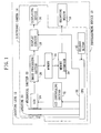
- Fig. 1 is a block diagram showing the structure of a photographing device according to the present embodiment.
- the photographing device 10 is configured by connecting a recording medium 16 to an electronic camera 14 of the invention to which a shooting lens 12 is fixed.
- the electronic camera 14 includes an aperture 20, a mechanical shutter 22, a CCD 24 (image sensor), an image processing section 26, a display circuit 28, a displaying device 30, a CCD controlling section 32, a memory 34, a memory interface 36, a CPU 38, and a release button 40.
- the CCD 24 includes a large number of photoelectric conversion elements and a large number of charge transfer electrodes both formed on a semiconductor substrate (not shown).
- the CCD 24 has a substrate voltage controlling terminal (not shown) that can make a switch between a moving-image photographing mode and a still-image photographing mode.
- An image pickup section described in the claims corresponds to the aperture 20, the mechanical shutter 22, the CCD 24, and the image processing section 26.
- a displaying section described in the claims corresponds to the display circuit 28 and the displaying device 30.
- a release section described in the claims includes only the release button 40.
- a shooting mode controlling section described in the claims corresponds to the CCD controlling section 32 and the CPU 38.
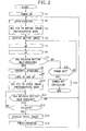
- Fig. 2 is a flowchart showing the shooting operation of the photographing device 10 of the present embodiment. The shooting operation will be described below in order of the step numbers shown in Fig. 2 .
- the CPU 38 opens the aperture of the shooting lens 12 by the aperture 20. At this moment, the release button 40 is not yet depressed, but is set to the standby mode.
- the CCD controlling section 32 supplies the substrate voltage controlling terminal of the CCD 24 with a voltage for preventing the blooming (corresponding to a control of electric potential difference described in claims) and sets the CCD 24 to the moving-image photographing mode.
- the control of electric potential difference makes, for example, the electric potential differences between the photoelectric conversion elements and semiconductor substrate smaller. In this case, when the charges accumulated in a photoelectric conversion element reach a certain amount, charges are ejected from the photoelectric conversion element to the semiconductor substrate, thereby preventing the leakage of charges between adjacent photoelectric conversion elements.
- the moving-image photographing mode corresponds to an appropriate mode for moving-image photographing described in the claims.
- the CCD 24 accumulates the light energy, which is received from an object (not shown) through the shooting lens 12, as charges.
- the image processing section 26 (continuously) reads out the charges, which are accumulated by the CCD 24, at predetermined intervals (charge accumulation time) as electrical signals to convert into digital data.
- the image processing section 26 performs color processing on the digital data to output to the display circuit 28 and the memory 34 as image data.
- the display circuit 28 performs an imaging process on the image data for output.
- the displaying device 30 displays the image data, which is continuously output from the display circuit 28, as a moving image.
- the time interval (charge accumulation time) during which the image processing section 26 reads out the charges from the CCD 24 is controlled by the CPU 38 and the CCD controlling section 32.
- the CPU 38 sets the shutter speed of the mechanical shutter 22 and the aperture of the shooting lens 12 (F-value) for shooting according to the brightness of an object and the distance between the shooting lens 12 and the object (auto exposure (AE)).
- the CPU 38 adjusts the position of the shooting lens 12, i.e., the distance between the shooting lens 12 and CCD 24, according the distance between an object and the shooting lens 12 (auto focus (AF)).
- the release button 40 When the release button 40 is half-pressed by the user, it is switched to the preparation mode and issues through the CPU 38 and the CCD controlling section 32 a command to prepare shooting. After that, the process proceeds to step S8.
- the shooting preparation here corresponds to the operations in steps S8 to S10.
- step S15 If the release button 40 is not pressed, the process proceeds to step S15.
- the CPU 38 narrows the aperture of the shooting lens 12 by the aperture 20 according to the F-value set in step S5. That is, an amount of the light from an object through the shooting lens 12 and incident on the CCD 24 is physically adjusted and fixed by the aperture 20.
- the CPU 38 fixes the position of the shooting lens 12 and the shutter speed of the mechanical shutter 22 for shooting.
- the CCD controlling section 32 changes a voltage supplied to the substrate voltage controlling terminal of the CCD 24 and sets the CCD 24 to the still-image photographing mode.
- This voltage change is performed, for example, so as to increase the voltage difference between the photoelectric conversion elements and the semiconductor substrate. In this case, since an amount of the charges that the photoelectric conversion elements can accumulate becomes larger, the dynamic range also becomes wider.
- the still-image photographing mode corresponds to an appropriate mode for still-image photographing described in the claims.
- step S12 When the release button 40 is kept half-pressed, the process proceeds to step S12. When the release button 40 is released by the user, the process returns to step S2.
- step S13 When the release button 40 is fully pressed by the user, it issues through the CPU 38 a command to start shooting and the process proceeds to step S13. When the release button 40 is still kept half-pressed, the process returns to step S11.
- the CPU 38 instructs the display circuit 28 and the displaying device 30 to switch the display of the image of an object from a moving image to still image display.
- the CPU 38 makes the mechanical shutter 22 operate with the shutter speed fixed in step S9. While the mechanical shutter 22 is open, charges are accumulated in the CCD 24.
- the image processing section 26 reads out the charges as electrical signals.
- the image processing section 26 converts the read out electrical signals into digital data and then performs color processing on the digital data to output to the memory 34 as image data.
- the image data stored in the memory 34 is recorded through the memory interface 36 into the recording medium 16 (end of shooting), and the process returns to step S2.
- step S5 When the power supply button is kept in the on state, the process returns to step S5.
- step S16 When the power supply button is turned off, the process proceeds to step S16.
- the operation to switch the image sensor to the still-image photographing mode (corresponding to step S10 in the present embodiment) is performed to start shooting.
- the shooting operation mechanism of the present embodiment is given as follows.
- the CPU 38 and the CCD controlling section 32 set the CCD 24 to the moving-image photographing mode.
- the release button 40 is switched to the preparation mode and issues a command to prepare shooting when being half-pressed in the standby mode.
- the CPU 38 and the CCD controlling section 32 set the CCD 24 to the still-image photographing mode.
- the release button 40 is fully pressed during the preparation mode, it is switched to the shooting mode and issues a command to start shooting.
- a difference from the conventional operation mechanism is that, after the release button 40 is half-pressed in step S7, the aperture of the shooting lens 12 is adjusted and then the CCD 24 is switched to the still-image photographing mode. Therefore, after the release button 40 is fully pressed by the user in step S12, shooting can be started without changing the modes of the CCD 24. As a result, the release time lag can be made shorter than in the conventional electronic camera.
- the displaying device 30 displays the image of an object as a moving image until the release button 40 is fully pressed in step S12. Therefore, the user can select a photo composition on the basis of the image of an object displayed on the displaying device 30 as a moving image.
- step S8 the CCD 24 is switched to the still-image photographing mode. Therefore, while the CCD 24 captures a moving image in the still-image photographing mode (steps S10 to S12), the amount of the light received by the CCD 24 is small. Accordingly, while the CCD 24 captures a moving image in the still-image photographing mode, the occurrence of the blooming can be prevented.
- CMOS and the like may be used as an image sensor.
- the electronic camera 14 may include the shooting lens 12 or the recording medium 16.
- the shooting mode controlling section sets the image pickup section to an appropriate mode for still-image photographing when the release section is in the preparation mode. Therefore, when the user operates the release section to start shooting, the image pickup section has already been set to an appropriate mode for still-image photographing. Accordingly, it is not necessary to switch the modes of the image pickup section, immediately before the image pickup section starts shooting. As a result, the release time lag can be reduced comparing to that of the conventional camera.
Landscapes
- Engineering & Computer Science (AREA)
- Multimedia (AREA)
- Signal Processing (AREA)
- Studio Devices (AREA)
- Transforming Light Signals Into Electric Signals (AREA)
- Details Of Cameras Including Film Mechanisms (AREA)
- Exposure Control For Cameras (AREA)
Claims (2)
- Elektronische Kamera, umfassend einen Bildaufnahmeteil (20, 22, 24, 26), der von einem Objekt durch eine Linse (12) empfangenes Licht in ein elektrisches Signal verwandelt, um Bilddaten zu erzeugen, wobei der Aufnahmeteil (20, 22, 24, 26) einen Bildsensor (24) aufweist,
ferner umfassend einen Ausgabeteil (28, 30), der die durch den Bildaufnahmeteil (20, 22, 24, 26) erzeugten Bilddaten anzeigt; und
einen Auslöseteil (40) mit einem Auslöseknopf, wobei dieser Auslöseteil (40) einen Standby-Modus, einen Vorbereitungsmodus und einen Abbildungsmodus aufweist, der Auslöseteil (40) von dem Standby-Modus auf den Vorbereitungsmodus schaltet und den Bildaufnahmeteil (20, 22, 24, 26) anweist, sich für das Abbilden vorzubereiten, sobald ein Benutzerbefehl empfangen wird und der Auslöseknopf halb eingedrückt wird, und wobei der Auslöseteil (40) von dem Vorbereitungsmodus auf den Abbildungsmodus schaltet und den Bildaufnahmeteil (20, 22, 24, 26) anweist, mit dem Abbilden zu beginnen, sobald der Benutzerbefehl übertragen und der Auslöseknopf vollständig eingedrückt wird,
wobei der Bildsensor (24) einen geeigneten Betriebsmodus zur Bewegungsbild-Fotografie und einen geeigneten Betriebsmodus zur Standbild-Fotografie aufweist; und
der Bildsensor (24) mehrere fotoelektrische Umwandlungselemente sowie mehrere Ladungsübertragung-Elektroden aufweist,
dadurch gekennzeichnet, daß
ein Abbildungsmodus-Steuerteil (32, 38) den Bildsensor (24) auf den geeigneten Betriebsmodus für die Bewegungsbild-Fotografie einstellt, bei dem Aufhellen durch Steuerung der elektrischen Potentialdifferenz in dem Bildsensor (24) verhindert wird, wenn sich der Auslöseteil (40) in dem Standby-Modus befindet,
und sobald der Auslöseteil (40) in den Vorbereitungsmodus geschaltet wird, der Abbildungsmodus-Steuerteil (32, 38) zunächst eine Öffnung (20) der Linse (12) gemäß einer Lichtmenge einstellt, die von dem Objekt empfangen wird, wobei die Einstellung durch Verengen der Öffnung der Linse (12) durch diese Öffnung (20) durchgeführt und dann der Bildsensor (24) auf den geeigneten Betriebsmodus für Standbild-Fotografie eingestellt wird, in dem die Steuerung der elektrischen Potentialdifferenz des Bildsensors (24) nicht erfolgt,
und daß der Auslöseteil (40) in den Abbildungsmodus geschaltet wird, und der Ausgabeteil (28, 30) ein sich bewegendes Bild eines Gegenstandes zeigt, bis der Auslöseteil (40) von dem Vorbereitungsmodus in den Abbildungsmodus geschaltet wird. - Elektronische Kamera nach Anspruch 1, dadurch gekennzeichnet, daß der Auslöseknopf den Auslöseteil (40) in den Standby-Modus schaltet, nachdem der auf ihm lastende Druck weggenommen ist.
Applications Claiming Priority (3)
| Application Number | Priority Date | Filing Date | Title |
|---|---|---|---|
| JP2002154006 | 2002-05-28 | ||
| JP2002154006A JP3757906B2 (ja) | 2002-05-28 | 2002-05-28 | 電子カメラ |
| PCT/JP2003/006603 WO2003101092A1 (en) | 2002-05-28 | 2003-05-27 | Electronic camera |
Publications (3)
| Publication Number | Publication Date |
|---|---|
| EP1526718A1 EP1526718A1 (de) | 2005-04-27 |
| EP1526718A4 EP1526718A4 (de) | 2007-04-04 |
| EP1526718B1 true EP1526718B1 (de) | 2010-06-16 |
Family
ID=29561339
Family Applications (1)
| Application Number | Title | Priority Date | Filing Date |
|---|---|---|---|
| EP03733094A Expired - Lifetime EP1526718B1 (de) | 2002-05-28 | 2003-05-27 | Elektronische kamera |
Country Status (6)
| Country | Link |
|---|---|
| US (1) | US7489343B2 (de) |
| EP (1) | EP1526718B1 (de) |
| JP (1) | JP3757906B2 (de) |
| CN (1) | CN100380927C (de) |
| DE (1) | DE60333015D1 (de) |
| WO (1) | WO2003101092A1 (de) |
Families Citing this family (11)
| Publication number | Priority date | Publication date | Assignee | Title |
|---|---|---|---|---|
| JP4381053B2 (ja) * | 2003-08-07 | 2009-12-09 | 三洋電機株式会社 | 撮像装置 |
| JP4054918B2 (ja) * | 2004-03-26 | 2008-03-05 | カシオ計算機株式会社 | 撮像装置、撮影制御方法及び撮影制御プログラム |
| JP2007110178A (ja) * | 2005-10-11 | 2007-04-26 | Sanyo Electric Co Ltd | 静止画と動画を撮影可能なカメラ機器 |
| EP2282521A3 (de) * | 2005-12-06 | 2011-10-05 | Panasonic Corporation | Digitalkamera |
| JP5086731B2 (ja) * | 2006-08-10 | 2012-11-28 | ペンタックスリコーイメージング株式会社 | カメラ |
| US7783191B2 (en) | 2006-08-10 | 2010-08-24 | Hoya Corporation | Digital camera |
| US20080266438A1 (en) * | 2007-04-30 | 2008-10-30 | Henrik Eliasson | Digital camera and method of operation |
| JP2009118215A (ja) | 2007-11-07 | 2009-05-28 | Canon Inc | 撮像装置 |
| KR101239952B1 (ko) * | 2008-03-03 | 2013-03-06 | 삼성전자주식회사 | 화상형성장치 및 그 제어방법 |
| JP5171398B2 (ja) * | 2008-06-02 | 2013-03-27 | 三洋電機株式会社 | 撮像装置 |
| JP5159589B2 (ja) * | 2008-12-08 | 2013-03-06 | キヤノン株式会社 | 撮像装置 |
Family Cites Families (12)
| Publication number | Priority date | Publication date | Assignee | Title |
|---|---|---|---|---|
| JPS58117776A (ja) * | 1981-12-30 | 1983-07-13 | Sony Corp | 固体撮像装置 |
| US5185669A (en) * | 1990-10-01 | 1993-02-09 | Sony Corporation | Still video camera with white balance and image pickup lens adjustment |
| US5703638A (en) * | 1991-09-25 | 1997-12-30 | Canon Kabushiki Kaisha | Image pickup apparatus for moving image photographing or for still image photographing |
| JP3847811B2 (ja) * | 1995-06-30 | 2006-11-22 | キヤノン株式会社 | 撮像装置 |
| JPH10136244A (ja) * | 1996-11-01 | 1998-05-22 | Olympus Optical Co Ltd | 電子的撮像装置 |
| JPH11212177A (ja) * | 1998-01-22 | 1999-08-06 | Ricoh Co Ltd | カメラ |
| GB9809679D0 (en) * | 1998-05-06 | 1998-07-01 | Xerox Corp | Portable text capturing method and device therefor |
| JP3820497B2 (ja) * | 1999-01-25 | 2006-09-13 | 富士写真フイルム株式会社 | 撮像装置及び自動露出制御の補正処理方法 |
| JP3596860B2 (ja) * | 1999-08-27 | 2004-12-02 | キヤノン株式会社 | 撮像装置 |
| JP3877474B2 (ja) * | 1999-08-03 | 2007-02-07 | 三洋電機株式会社 | 電子カメラ |
| JP3679693B2 (ja) * | 2000-07-31 | 2005-08-03 | 三洋電機株式会社 | オートフォーカスカメラ |
| JP4020591B2 (ja) * | 2001-03-02 | 2007-12-12 | 富士フイルム株式会社 | デジタルカメラ及び電圧供給回路 |
-
2002
- 2002-05-28 JP JP2002154006A patent/JP3757906B2/ja not_active Expired - Fee Related
-
2003
- 2003-05-27 US US10/515,379 patent/US7489343B2/en not_active Expired - Fee Related
- 2003-05-27 DE DE60333015T patent/DE60333015D1/de not_active Expired - Lifetime
- 2003-05-27 WO PCT/JP2003/006603 patent/WO2003101092A1/ja not_active Ceased
- 2003-05-27 CN CNB038121328A patent/CN100380927C/zh not_active Expired - Fee Related
- 2003-05-27 EP EP03733094A patent/EP1526718B1/de not_active Expired - Lifetime
Also Published As
| Publication number | Publication date |
|---|---|
| CN1656795A (zh) | 2005-08-17 |
| WO2003101092A1 (en) | 2003-12-04 |
| US7489343B2 (en) | 2009-02-10 |
| CN100380927C (zh) | 2008-04-09 |
| EP1526718A1 (de) | 2005-04-27 |
| EP1526718A4 (de) | 2007-04-04 |
| JP3757906B2 (ja) | 2006-03-22 |
| JP2003348433A (ja) | 2003-12-05 |
| US20050243179A1 (en) | 2005-11-03 |
| DE60333015D1 (de) | 2010-07-29 |
Similar Documents
| Publication | Publication Date | Title |
|---|---|---|
| US8300142B2 (en) | Imaging apparatus having adjustable power supply based on imager sensitivity | |
| US5926218A (en) | Electronic camera with dual resolution sensors | |
| JP5276308B2 (ja) | 撮像装置およびその制御方法 | |
| US9374520B2 (en) | Digital image processing apparatus and method of controlling the same | |
| JP4446787B2 (ja) | 撮像装置、および表示制御方法 | |
| JP5967865B2 (ja) | 撮像装置、撮像装置の制御方法及びプログラム | |
| EP2534827B1 (de) | Bildaufnahmevorrichtung und steuerungsverfahren dafür | |
| EP1526718B1 (de) | Elektronische kamera | |
| US7941041B2 (en) | Image pickup apparatus | |
| JP2004260797A (ja) | 撮像装置、撮像方法および記録媒体 | |
| JP2001350170A (ja) | デジタルカメラ | |
| JP5063372B2 (ja) | 画像処理装置、制御方法、及びプログラム | |
| JP4086337B2 (ja) | 撮像装置 | |
| JP4095630B2 (ja) | 撮像装置 | |
| JP4355855B2 (ja) | 撮像装置、撮影切替方法、及びプログラム | |
| JP4757223B2 (ja) | 撮像装置及びその制御方法 | |
| JP4307320B2 (ja) | 撮像装置 | |
| JP4993683B2 (ja) | 撮像装置及びその制御方法 | |
| JP2000358189A (ja) | 撮像装置及びその制御方法 | |
| JP2004363778A (ja) | 撮像装置 | |
| JP2004187085A (ja) | 撮像装置 | |
| JP2007034175A (ja) | 撮像装置 | |
| JP2005005870A (ja) | 撮像装置 | |
| JP2006053383A (ja) | 撮影装置 | |
| JP2007306437A (ja) | 撮像装置およびその制御方法 |
Legal Events
| Date | Code | Title | Description |
|---|---|---|---|
| PUAI | Public reference made under article 153(3) epc to a published international application that has entered the european phase |
Free format text: ORIGINAL CODE: 0009012 |
|
| 17P | Request for examination filed |
Effective date: 20041222 |
|
| AK | Designated contracting states |
Kind code of ref document: A1 Designated state(s): AT BE BG CH CY CZ DE DK EE ES FI FR GB GR HU IE IT LI LU MC NL PT RO SE SI SK TR |
|
| RBV | Designated contracting states (corrected) |
Designated state(s): DE FR GB |
|
| A4 | Supplementary search report drawn up and despatched |
Effective date: 20070302 |
|
| RIC1 | Information provided on ipc code assigned before grant |
Ipc: H04N 5/232 20060101AFI20031211BHEP |
|
| 17Q | First examination report despatched |
Effective date: 20070622 |
|
| GRAP | Despatch of communication of intention to grant a patent |
Free format text: ORIGINAL CODE: EPIDOSNIGR1 |
|
| GRAS | Grant fee paid |
Free format text: ORIGINAL CODE: EPIDOSNIGR3 |
|
| GRAA | (expected) grant |
Free format text: ORIGINAL CODE: 0009210 |
|
| AK | Designated contracting states |
Kind code of ref document: B1 Designated state(s): DE FR GB |
|
| RAP2 | Party data changed (patent owner data changed or rights of a patent transferred) |
Owner name: NIKON CORPORATION |
|
| REF | Corresponds to: |
Ref document number: 60333015 Country of ref document: DE Date of ref document: 20100729 Kind code of ref document: P |
|
| PLBE | No opposition filed within time limit |
Free format text: ORIGINAL CODE: 0009261 |
|
| STAA | Information on the status of an ep patent application or granted ep patent |
Free format text: STATUS: NO OPPOSITION FILED WITHIN TIME LIMIT |
|
| 26N | No opposition filed |
Effective date: 20110317 |
|
| REG | Reference to a national code |
Ref country code: DE Ref legal event code: R097 Ref document number: 60333015 Country of ref document: DE Effective date: 20110316 |
|
| REG | Reference to a national code |
Ref country code: FR Ref legal event code: PLFP Year of fee payment: 14 |
|
| REG | Reference to a national code |
Ref country code: FR Ref legal event code: PLFP Year of fee payment: 15 |
|
| REG | Reference to a national code |
Ref country code: FR Ref legal event code: PLFP Year of fee payment: 16 |
|
| PGFP | Annual fee paid to national office [announced via postgrant information from national office to epo] |
Ref country code: DE Payment date: 20190514 Year of fee payment: 17 |
|
| PGFP | Annual fee paid to national office [announced via postgrant information from national office to epo] |
Ref country code: GB Payment date: 20190522 Year of fee payment: 17 |
|
| PGFP | Annual fee paid to national office [announced via postgrant information from national office to epo] |
Ref country code: FR Payment date: 20200414 Year of fee payment: 18 |
|
| REG | Reference to a national code |
Ref country code: DE Ref legal event code: R119 Ref document number: 60333015 Country of ref document: DE |
|
| GBPC | Gb: european patent ceased through non-payment of renewal fee |
Effective date: 20200527 |
|
| PG25 | Lapsed in a contracting state [announced via postgrant information from national office to epo] |
Ref country code: GB Free format text: LAPSE BECAUSE OF NON-PAYMENT OF DUE FEES Effective date: 20200527 |
|
| PG25 | Lapsed in a contracting state [announced via postgrant information from national office to epo] |
Ref country code: DE Free format text: LAPSE BECAUSE OF NON-PAYMENT OF DUE FEES Effective date: 20201201 |
|
| PG25 | Lapsed in a contracting state [announced via postgrant information from national office to epo] |
Ref country code: FR Free format text: LAPSE BECAUSE OF NON-PAYMENT OF DUE FEES Effective date: 20210531 |