EP1526392A2 - Dispositif et procédé pour la détection rapide d'objets cachés - Google Patents
Dispositif et procédé pour la détection rapide d'objets cachés Download PDFInfo
- Publication number
- EP1526392A2 EP1526392A2 EP04255584A EP04255584A EP1526392A2 EP 1526392 A2 EP1526392 A2 EP 1526392A2 EP 04255584 A EP04255584 A EP 04255584A EP 04255584 A EP04255584 A EP 04255584A EP 1526392 A2 EP1526392 A2 EP 1526392A2
- Authority
- EP
- European Patent Office
- Prior art keywords
- region
- data
- ray
- detectors
- stage
- Prior art date
- Legal status (The legal status is an assumption and is not a legal conclusion. Google has not performed a legal analysis and makes no representation as to the accuracy of the status listed.)
- Withdrawn
Links
- 238000000034 method Methods 0.000 title claims abstract description 100
- 238000001514 detection method Methods 0.000 title abstract description 18
- 238000007689 inspection Methods 0.000 claims abstract description 147
- 239000000463 material Substances 0.000 claims abstract description 68
- 230000008569 process Effects 0.000 claims abstract description 53
- 238000012545 processing Methods 0.000 claims abstract description 23
- 238000004891 communication Methods 0.000 claims abstract description 11
- 238000001228 spectrum Methods 0.000 claims description 65
- 230000005540 biological transmission Effects 0.000 claims description 61
- 238000013528 artificial neural network Methods 0.000 claims description 48
- 230000005855 radiation Effects 0.000 claims description 34
- 238000004422 calculation algorithm Methods 0.000 claims description 17
- 239000002360 explosive Substances 0.000 claims description 12
- 230000004044 response Effects 0.000 claims description 9
- 239000002131 composite material Substances 0.000 claims description 5
- 229910052751 metal Inorganic materials 0.000 claims description 4
- 239000002184 metal Substances 0.000 claims description 4
- 238000007363 ring formation reaction Methods 0.000 claims description 3
- 238000012937 correction Methods 0.000 claims description 2
- 239000002117 illicit drug Substances 0.000 claims description 2
- 230000007423 decrease Effects 0.000 abstract description 3
- 238000012549 training Methods 0.000 description 51
- 210000002569 neuron Anatomy 0.000 description 28
- 230000009977 dual effect Effects 0.000 description 21
- 230000006870 function Effects 0.000 description 17
- 238000000411 transmission spectrum Methods 0.000 description 16
- 238000002591 computed tomography Methods 0.000 description 15
- 230000000875 corresponding effect Effects 0.000 description 14
- 230000035945 sensitivity Effects 0.000 description 14
- 230000003595 spectral effect Effects 0.000 description 14
- 230000001537 neural effect Effects 0.000 description 13
- 239000000126 substance Substances 0.000 description 13
- 238000005259 measurement Methods 0.000 description 12
- 238000003491 array Methods 0.000 description 10
- 230000033001 locomotion Effects 0.000 description 9
- 239000000203 mixture Substances 0.000 description 9
- 239000013598 vector Substances 0.000 description 9
- 239000000523 sample Substances 0.000 description 8
- 238000013459 approach Methods 0.000 description 7
- 230000000694 effects Effects 0.000 description 7
- 238000003384 imaging method Methods 0.000 description 7
- 230000003993 interaction Effects 0.000 description 7
- 238000004458 analytical method Methods 0.000 description 6
- 238000010586 diagram Methods 0.000 description 6
- 230000036961 partial effect Effects 0.000 description 5
- 230000008901 benefit Effects 0.000 description 4
- 230000008859 change Effects 0.000 description 4
- 230000001427 coherent effect Effects 0.000 description 4
- 230000004048 modification Effects 0.000 description 4
- 238000012986 modification Methods 0.000 description 4
- 230000000946 synaptic effect Effects 0.000 description 4
- 238000012360 testing method Methods 0.000 description 4
- 230000006978 adaptation Effects 0.000 description 3
- 230000002238 attenuated effect Effects 0.000 description 3
- 230000002829 reductive effect Effects 0.000 description 3
- 238000012216 screening Methods 0.000 description 3
- IJGRMHOSHXDMSA-UHFFFAOYSA-N Atomic nitrogen Chemical compound N#N IJGRMHOSHXDMSA-UHFFFAOYSA-N 0.000 description 2
- 229910000978 Pb alloy Inorganic materials 0.000 description 2
- 230000009471 action Effects 0.000 description 2
- 230000000903 blocking effect Effects 0.000 description 2
- 238000004364 calculation method Methods 0.000 description 2
- 238000012512 characterization method Methods 0.000 description 2
- 230000001010 compromised effect Effects 0.000 description 2
- 239000013078 crystal Substances 0.000 description 2
- 239000003814 drug Substances 0.000 description 2
- 229940079593 drug Drugs 0.000 description 2
- 230000004907 flux Effects 0.000 description 2
- 210000004209 hair Anatomy 0.000 description 2
- 230000000670 limiting effect Effects 0.000 description 2
- 239000011368 organic material Substances 0.000 description 2
- 238000007781 pre-processing Methods 0.000 description 2
- 230000001932 seasonal effect Effects 0.000 description 2
- MARUHZGHZWCEQU-UHFFFAOYSA-N 5-phenyl-2h-tetrazole Chemical compound C1=CC=CC=C1C1=NNN=N1 MARUHZGHZWCEQU-UHFFFAOYSA-N 0.000 description 1
- OKTJSMMVPCPJKN-UHFFFAOYSA-N Carbon Chemical compound [C] OKTJSMMVPCPJKN-UHFFFAOYSA-N 0.000 description 1
- UFHFLCQGNIYNRP-UHFFFAOYSA-N Hydrogen Chemical compound [H][H] UFHFLCQGNIYNRP-UHFFFAOYSA-N 0.000 description 1
- TZRXHJWUDPFEEY-UHFFFAOYSA-N Pentaerythritol Tetranitrate Chemical compound [O-][N+](=O)OCC(CO[N+]([O-])=O)(CO[N+]([O-])=O)CO[N+]([O-])=O TZRXHJWUDPFEEY-UHFFFAOYSA-N 0.000 description 1
- XUIMIQQOPSSXEZ-UHFFFAOYSA-N Silicon Chemical compound [Si] XUIMIQQOPSSXEZ-UHFFFAOYSA-N 0.000 description 1
- 229910000831 Steel Inorganic materials 0.000 description 1
- 238000002441 X-ray diffraction Methods 0.000 description 1
- FYDSPEWNDZOWPU-UHFFFAOYSA-N [3-nitrooxy-2,2-bis(nitrooxymethyl)propyl] nitrate;1,3,5-trinitro-1,3,5-triazinane Chemical compound [O-][N+](=O)N1CN([N+]([O-])=O)CN([N+]([O-])=O)C1.[O-][N+](=O)OCC(CO[N+]([O-])=O)(CO[N+]([O-])=O)CO[N+]([O-])=O FYDSPEWNDZOWPU-UHFFFAOYSA-N 0.000 description 1
- 238000010521 absorption reaction Methods 0.000 description 1
- 230000035508 accumulation Effects 0.000 description 1
- 238000009825 accumulation Methods 0.000 description 1
- 230000004913 activation Effects 0.000 description 1
- 230000003044 adaptive effect Effects 0.000 description 1
- 229910052782 aluminium Inorganic materials 0.000 description 1
- XAGFODPZIPBFFR-UHFFFAOYSA-N aluminium Chemical compound [Al] XAGFODPZIPBFFR-UHFFFAOYSA-N 0.000 description 1
- QVGXLLKOCUKJST-UHFFFAOYSA-N atomic oxygen Chemical compound [O] QVGXLLKOCUKJST-UHFFFAOYSA-N 0.000 description 1
- 238000013529 biological neural network Methods 0.000 description 1
- 210000004556 brain Anatomy 0.000 description 1
- QWUZMTJBRUASOW-UHFFFAOYSA-N cadmium tellanylidenezinc Chemical compound [Zn].[Cd].[Te] QWUZMTJBRUASOW-UHFFFAOYSA-N 0.000 description 1
- 229910052799 carbon Inorganic materials 0.000 description 1
- 230000015556 catabolic process Effects 0.000 description 1
- 238000007635 classification algorithm Methods 0.000 description 1
- -1 clothing Substances 0.000 description 1
- 230000002860 competitive effect Effects 0.000 description 1
- 238000010276 construction Methods 0.000 description 1
- 230000002596 correlated effect Effects 0.000 description 1
- 230000003247 decreasing effect Effects 0.000 description 1
- 238000006731 degradation reaction Methods 0.000 description 1
- 230000001419 dependent effect Effects 0.000 description 1
- 238000009795 derivation Methods 0.000 description 1
- 238000003708 edge detection Methods 0.000 description 1
- 238000005516 engineering process Methods 0.000 description 1
- 230000007613 environmental effect Effects 0.000 description 1
- 235000013305 food Nutrition 0.000 description 1
- 230000014509 gene expression Effects 0.000 description 1
- 239000001257 hydrogen Substances 0.000 description 1
- 229910052739 hydrogen Inorganic materials 0.000 description 1
- 230000000977 initiatory effect Effects 0.000 description 1
- 238000011835 investigation Methods 0.000 description 1
- 230000001678 irradiating effect Effects 0.000 description 1
- 238000002372 labelling Methods 0.000 description 1
- 238000012886 linear function Methods 0.000 description 1
- 230000004807 localization Effects 0.000 description 1
- 239000007769 metal material Substances 0.000 description 1
- 150000002739 metals Chemical class 0.000 description 1
- 238000012544 monitoring process Methods 0.000 description 1
- 229910052757 nitrogen Inorganic materials 0.000 description 1
- 230000003287 optical effect Effects 0.000 description 1
- 230000008520 organization Effects 0.000 description 1
- 239000001301 oxygen Substances 0.000 description 1
- 229910052760 oxygen Inorganic materials 0.000 description 1
- 238000003909 pattern recognition Methods 0.000 description 1
- 230000002093 peripheral effect Effects 0.000 description 1
- 230000000644 propagated effect Effects 0.000 description 1
- 230000001902 propagating effect Effects 0.000 description 1
- 235000021067 refined food Nutrition 0.000 description 1
- 230000002787 reinforcement Effects 0.000 description 1
- 238000005316 response function Methods 0.000 description 1
- 238000005070 sampling Methods 0.000 description 1
- 238000000926 separation method Methods 0.000 description 1
- 238000007493 shaping process Methods 0.000 description 1
- 229910052710 silicon Inorganic materials 0.000 description 1
- 239000010703 silicon Substances 0.000 description 1
- 239000010959 steel Substances 0.000 description 1
- 210000000225 synapse Anatomy 0.000 description 1
- 230000001360 synchronised effect Effects 0.000 description 1
- 230000000007 visual effect Effects 0.000 description 1
- 238000011179 visual inspection Methods 0.000 description 1
Images


Classifications
-
- G01V5/22—
-
- G—PHYSICS
- G01—MEASURING; TESTING
- G01R—MEASURING ELECTRIC VARIABLES; MEASURING MAGNETIC VARIABLES
- G01R27/00—Arrangements for measuring resistance, reactance, impedance, or electric characteristics derived therefrom
- G01R27/02—Measuring real or complex resistance, reactance, impedance, or other two-pole characteristics derived therefrom, e.g. time constant
- G01R27/04—Measuring real or complex resistance, reactance, impedance, or other two-pole characteristics derived therefrom, e.g. time constant in circuits having distributed constants, e.g. having very long conductors or involving high frequencies
- G01R27/06—Measuring reflection coefficients; Measuring standing-wave ratio
-
- G01V5/222—
-
- G—PHYSICS
- G01—MEASURING; TESTING
- G01F—MEASURING VOLUME, VOLUME FLOW, MASS FLOW OR LIQUID LEVEL; METERING BY VOLUME
- G01F23/00—Indicating or measuring liquid level or level of fluent solid material, e.g. indicating in terms of volume or indicating by means of an alarm
- G01F23/22—Indicating or measuring liquid level or level of fluent solid material, e.g. indicating in terms of volume or indicating by means of an alarm by measuring physical variables, other than linear dimensions, pressure or weight, dependent on the level to be measured, e.g. by difference of heat transfer of steam or water
- G01F23/28—Indicating or measuring liquid level or level of fluent solid material, e.g. indicating in terms of volume or indicating by means of an alarm by measuring physical variables, other than linear dimensions, pressure or weight, dependent on the level to be measured, e.g. by difference of heat transfer of steam or water by measuring the variations of parameters of electromagnetic or acoustic waves applied directly to the liquid or fluent solid material
- G01F23/284—Electromagnetic waves
-
- G—PHYSICS
- G01—MEASURING; TESTING
- G01N—INVESTIGATING OR ANALYSING MATERIALS BY DETERMINING THEIR CHEMICAL OR PHYSICAL PROPERTIES
- G01N22/00—Investigating or analysing materials by the use of microwaves or radio waves, i.e. electromagnetic waves with a wavelength of one millimetre or more
Definitions
- the present invention relates generally to X-ray based methods and systems for detection of concealed threats, and threat resolution, and more specifically to improved methods and systems, using dual stage scanning to process luggage for faster inspection with reduced false alarm rate.
- Radiographic projection images which are then interpreted by an operator. These radiographs are often difficult to interpret because objects are superimposed. A trained operator must study and interpret each image to render an opinion on whether or not a target of interest, a threat, is present. With a large number of such radiographs to be interpreted, and with the implied requirement to keep the number of false alarms low, operator fatigue and distraction can compromise detection performance.
- CT images do not suffer much from the super-positioning problem present in standard radiographs.
- conventional CT systems take considerable time to perform multiple scans, to capture data, and to reconstruct the images.
- the throughput of CT systems is generally low. Coupled with the size and expense of CT systems this limitation has hindered CT use in applications such as baggage inspection where baggage throughput is an important concern.
- CT alarms on critical mass and density of a threat but such properties are not unique to explosives.
- CT based systems suffer from high false alarm rate. Any such alarm is then to be cleared or confirmed by an operator, again interpreting images, or hand searching.
- detection systems based on X-ray diffraction, or coherent scatter are also known. Their primary purpose is not to acquire images but to obtain information about the molecular structure of the substances an object is composed of.
- the so-called diffraction or coherent scatter signature is based on BRAGG reflection, that is the interference pattern of X-ray light, which develops when X-rays are reflected by the molecular structure or electron density distribution of a substance.
- the resulting diffraction spectra can be analyzed to determine the molecular structure of the diffracting object, or at least to recognize similarity with any one of a number of spectra, which have previously been obtained from dangerous substances.
- United States Patent Nos. 4,754,469, 4,956,856, 5,008,911, 5,265,144, 5,600,700 and 6,054,712 describe methods and devices for examining substances, from biological tissues to explosives in luggage, by recording the spectra of coherent radiation scattered at various angles relative to an incident beam direction.
- U.S. Pat. No. 5,265,144 describes a device using concentric detecting rings for recording the radiation scattered at particular angles.
- Each of the prior art systems and methods suffer from low processing rates because the scatter interaction cross sections are relatively small and the exposure times required to obtain useful diffraction spectra are long, in the range of seconds and minutes.
- equipment performance has to combine high detection sensitivity and high threat specificity with high throughput, at the order of hundreds of bags per hour.
- U.S. Patent No. 5,182,764 discloses an apparatus for detecting concealed objects, such as explosives, drugs, or other contraband, using CT scanning.
- a pre-scanning approach is disclosed. Based upon the pre-scan data, selected locations for CT scanning are identified and CT scanning is undertaken at the selected locations.
- the inventors claim the pre-scan step reduces the scanning time required for each scanned item, therefore increasing throughput.
- the use of CT scanning is still inefficient, not threat specific, and does not allow for rapid scanning of objects.
- U.S. Patent No. 5,642,393 discloses a multi-view X-ray inspection probe that employs X-ray radiation transmitted through or scattered from an examined item to identify a suspicious region inside the item.
- An interface is used to receive X-ray data providing spatial information about the suspicious region and to provide this information to a selected material sensitive probe.
- the material sensitive probe such as a coherent scatter probe, then acquires material specific information about the previously identified suspicious region and provides it to a computer.
- the disclosed system does not, however, address critical problems that arise in the course of applying a scatter probe to a selected suspicious region, including the accurate identification of a suspicious region, correction of detected data, and the nature of processing algorithms used.
- an improved automatic threat detection and resolution system that captures data through an X-ray system and utilizes this data to identify threat items in a rapid, yet accurate, manner.
- the system is highly threat specific in order to reliably and automatically discern threats from innocuous materials and items while still being able to process in excess of 100 bags per hour.
- the system utilizes relatively inexpensive industrial components, and does not need special support facilities. Additionally, the system should provide for greater accuracy in utilizing pre-scan data to identify an inspection region and in processing scan data.
- One object of the present invention is to provide for an improved scanning process having a first stage to pre-select the locations of potential threats and a second stage to accurately identify the nature of the threat.
- the improved scanning process increases throughput by limiting the detailed inspection to a small fraction of the total bag volume, and it decreases the frequency of false alarms by applying threat specific analysis.
- Another object of the invention is to provide for improved processing techniques performed in association with various scanning systems.
- the improved processing techniques enable the substantially automated detection of threats and decrease the dependence on operator skill and performance.
- Another object of the invention is to provide for a method and system to screen for relatively small amounts of threat material.
- Another object of the invention is to provide for an improved method and system for screening for explosives in the form of thin sheets.
- Another object of the invention is to provide a screening solution at low cost by utilizing standard industrial components, including relatively low cost and rugged industrial X-ray systems and detector systems.
- one embodiment of the present invention provides an apparatus for identifying an object concealed within a container. These objects may be considered threats, such as an illegal drug, an explosive material, or a weapon.
- the apparatus comprises a first stage inspection system having at least two X-ray projection systems projecting in different directions to generate a first set of data, and a data processing system in data communication with the first stage inspection system.
- the processors process the first set of data to generate at least two images or image data files.
- the images are then subjected to a set of image interpretation algorithms, also processed by the processors, to identify target regions in the two images. Since the images are projected in different direction it is possible to back-project identified target regions and to locate those targets in system coordinates.
- the first stage inspection system locates potential threat items, regions, and/or areas, based on X-ray images, manual or automatic detection algorithms, and triangulation.
- a second stage inspection system discussed below, then focuses on the identified items, regions, and/or areas to produce characteristic signatures which are then used to determine whether a threat is, in fact, present.
- a target region is identified from the two images generated in the first stage inspection system by having an operator select a particular region displayed in the images.
- the operator directs a cursor, using an interface, such as a mouse, to position crosshairs on each of the two images.
- the two crosshairs determine a certain location in system coordinates.
- the selection for the cross hair location may occur based upon an X-ray image characteristic, such as the X-ray shadow of an object, seen in both images.
- the target selection process may be performed electronically.
- Target regions are identified from the two images by having a processor execute an algorithm to select regions in the images, which correspond to objects or mass accumulations. With the locations of each of the two images determined, the coordinates corresponding to the physical locations of the target region can be determined and used to direct the system, and, in particular, the conveyor.
- a plurality of control commands is produced and used to position, by a multiple-axis motion control system, the second stage inspection system such that an inspection region, at least partially, coincides with the determined target coordinates.
- the inspection region is positioned relative to the target region using a plurality of adjustable apertures that can be physically moved.
- the apertures can be ring-shaped with an adjustable diameter.
- the means for positioning the inspection volume relative to the target region comprises a motion-controlled conveyor operable to move in elevation as well as back and forth relative to the second stage inspection system.
- the inspection region can be moved across the conveyor by mounting the second stage inspection system on a C-arm which is motion controlled to move back and forth across the conveyor, or alternatively by employing a parallel set of fixed linear bearings and synchronized linear motion to effect the same relative movement.
- the second stage inspection system generates an inspection volume in space and produces a second set of data having an X-ray signature characteristic of the material in that inspection volume.
- the X-ray signature characteristic is a diffraction pattern, also called scatter spectrum, and an intensity level associated with that spectrum, and, in addition, a set of dual energy transmission measurements in close proximity to the ray path of the diffraction measurement.
- the second stage inspection system comprises a source of X-ray radiation.
- it comprises an energy dispersive detector.
- it comprises an array of transmission detectors.
- it comprises both an energy dispersive detector and an array of transmission detectors.
- the energy dispersive detector is used to produce a signature of the material in the inspection region and the array of transmission detectors is used to produce data defining at least one of mass, degree of attenuation, area, and average atomic number, of the material in a beampath.
- the array of transmission detectors is in a ring formation.
- the array of transmission detectors comprises high energy and low energy detectors. Data generated from the transmission detectors is used to determine a reference spectrum by identifying a spectrum associated with data generated from both the high energy detectors and the low energy detectors. The reference spectrum can be used to correct a diffraction spectrum or to correct for beam hardening.
- the present invention includes a method of automatically determining the existence of a threat based upon the second set of data. While a variety of algorithms can be employed for this task, a preferred approach is to use a neural network to process at least one of the first set of data or the second set of data to determine the existence of a threat.
- the neural network operates as a back-propagation network having a plurality of nodes and wherein the nodes are organized in a series of successive layers, each layer comprising at least one node that receives inputs from nodes in a prior layer and transmits outputs to nodes in a subsequent layer.
- the nodes in a first layer are weighted in accordance with their distance from at least one node in a second layer.
- the neural network is trained to determine the existence of the threat using a plurality of libraries, such as network accessible libraries, threat libraries, non-threat libraries, and/or other libraries.
- the methods and systems described herein are directed towards finding, locating, and confirming threat items and substances.
- threats may comprise explosives such as C4, RDX, Semtex, Seismoplast, PE4, TNT, dynamite, PETN, ANFO among others, as well as other contraband such as drugs.
- C4, RDX, Semtex, Seismoplast, PE4, TNT, dynamite, PETN, ANFO among others as well as other contraband such as drugs.
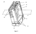
- a dual stage scanning system 100 comprises a housing 130, which encompasses a conveyor system 115 for moving containers, baggage, luggage, or similar object 110 through a plurality of scanning stages 150, 155.
- a sensor system 165 is connected at the entrance to determine when an object being scanned 110 enters the scan field and communicates with a controller [not shown] to activate or deactivate an X-ray radiation source, 170, 172, as needed.
- a lead lined tunnel 180 surrounds the conveyor to reduce radiation leakage outside the equipment. At least one radiation source is not expressly depicted in Figure 1 and would be visible if the system were viewed from the opposite side.
- the first stage 150 comprises two X-ray cameras held together by a support structure 220, such as a frame or yoke, for stability.
- a support structure 220 such as a frame or yoke, for stability.
- Each camera consists of an X-ray source 170, 171, a X-ray focusing means, such as a collimating slit comprised of a radio-opaque material, for example lead (not shown), and an array of detectors, 200, 201.
- the detectors are configured into a L-shape in order to save space.
- the detectors are appropriately positioned relative to the inspection region and X-ray source.
- a thin sheet of X-rays 210 is formed.
- a fan of pencil beams can be defined, shown as dashed lines in Figure 2, by connecting lines between the stationary focus, not shown, and channels in the detector array.
- a tunnel 180 Between focus and detector is a tunnel 180 through which the luggage is transported or moved using any means known in the art, including, for example, a conveyor 115, the surface of which is depicted in Figure 2.
- the conveyor belt support structure as well as the tunnel has windows constructed from materials essentially translucent to X-rays.
- the collimating slits and detector arrays are oriented so that the radiation-fans intersect the main conveyor surface within a few degrees of perpendicular relative to the conveyor surface.
- the two X-ray sources and their fans point in different directions.
- the detector arrays are mounted on printed circuit boards with a vector positioned normal to their surfaces directed to the X-ray focus.
- An exemplary printed circuit board has a capacity of 64 channels, and the boards are physically arranged in Venetian blind configuration.
- the detector arrays consist of linear arrays of silicon photodiodes that are covered with scintillation material, which produces light when exposed to X-rays. The light is detected by the photodiodes that produce corresponding photo current signals. The detectors measure to what degree the X-ray signal has attenuated due to passing through a defined inspection volume. Specifically, the detected data are converted to digital format, corrected for detector gain and offset, and then stored.
- the required processor means may comprise computing hardware, firmware and/or software known to persons of ordinary skill in the art.
- the present invention provides for the placement of at least two X-ray sources such that the directions of the X-ray projections emanating from the sources are mirrored relative to the central vertical plane. Therefore, from the perspective of a view along the path of conveyance through the first stage scanning system, at least one X-ray generator is mounted at a five o'clock position and at least one X-ray generator is mounted at the 7 o'clock position.
- first stage scanning system is not limited to the specific embodiments described above and that other variations are included within the scope of this invention.
- detector arrays are expanded from a single array to multiple parallel arrays of detectors.
- X-ray projections are taken using two-dimensional pixellated detector planes, without requiring the use of a conveyance means. It should be appreciated that, while the present invention will be further described using a description of the invention based on using the line scan configuration of single stationary foci and single line detector arrays in conjunction with a means of conveyance, the present invention includes other systems and methods that generate X-ray projection images and that such systems and methods can be used in the novel dual stage scanning system disclosed herein.
- Dual energy imaging can be utilized to display an image where materials of a metallic constituency are suppressed (not displayed) or materials of an organic constituency are suppressed. Having the ability to selectively display certain materials within images helps reduce image clutter. For example, when inspecting containers for masses or explosives, which have little or no metallic component, the "organic materials only" display is preferred.
- the dual energy approach can be further refined to automatically discriminate between similar materials of higher and lower relative atomic numbers, such as between a plastic comprised of more lower atomic number atoms like hydrogen and carbon and a plastic comprised of more higher atomic number elements like oxygen and nitrogen; or between aluminum (atomic number 13) and steel (atomic number 26).
- dual energy data is generated by using an X-ray tube with extended spectral emission, which is standard, in conjunction with arrays of stacked detectors, where the first detector is positioned to detect more of the lower energy, or so-called softer X-ray photons, and the second detector is positioned to detect the balance of the energy, namely the higher energy, or so-called harder, photons.
- the second detector is typically positioned behind the first detector.
- projection imaging As the first stage scanning step in this invention.
- Features shown in the projection images can be used by an operator to make a final decision on whether items identified in a container represent a threat of some type. Additionally, by taking projections from at least two different angles, it is possible to triangulate the location of a potential threat relative to the physical coordinates of the system and use those coordinates to perform a more specific and focused second stage scan. The triangulation process localizes certain items that generate features of interest in the images and identifies their location in the form of system coordinates.
- the images that form the basis of the triangulation process and that are used to identify a target region are first identified.
- the images are analyzed by an operator who visually and approximately determines a plurality of X-ray image characteristics, such as degree of attenuation and projected area, associated with mass, atomic number (identified using image color coding), and shape. Operators also use contextual information, such as an X-ray opaque organic mass in a transistor radio or a suspiciously thick suitcase wall.
- the analytical process is known to those of ordinary skill in the art and includes the interpretation of X-ray image characteristics.
- images are identified by determining the target regions automatically.
- the screening target is a mass of plastic explosive
- known algorithms working on dual energy X-ray projection image data, can be combined to automatically find such target.
- algorithm components include, but are not limited to, edge detection, watershed, and connected component labeling.
- a container 110 is moved on a conveyor 115 through a tunnel 180 in x-direction, perpendicular to the plane of the Figure.
- a first X-ray generator 170, C1 with an X-ray emitting focus projects a fan of X-rays 300 through a slit collimator onto an array of detectors mounted on printed circuit boards 200.
- One of ordinary skill in the art would appreciate that only a small sampling of detectors are shown in Figure 3 and that a typical system would have a far greater number of detectors, preferably 700 to 800, more preferably 740.
- the orientation of the fan plane is perpendicular to the conveyor surface.
- the detectors While a container is being moved along the conveyor surface, the detectors are read out repeatedly, and their signals are converted into digital format by detector electronics that are also mounted on the detector boards 200. The data are being processed and sorted further and stored in a computer [not shown] for display on a monitor [not shown]. Each horizontal line on the monitor corresponds to one particular detector in the array. Therefore, in a system using 740 detectors, the full image is composed of 740 lines.
- a second X-ray camera, C2 consisting of X-ray generator 171, slit collimator (not shown) and detector array 201 is mounted in a different orientation, and offset in conveyor direction, by typically 100mm.
- the detectors aligned with this camera are sampled essentially simultaneously with the detectors of the first camera and produce a second image displayed on a monitor.
- an item 340 located within the container 110 is recognized in the course of the first stage scan using a detection algorithm or by operator analysis, depending upon the system mode chosen. With the item 340 identified, the approximate centerline X-ray projections 330, 331 that pass through the object can be determined. Each of the centerlines 330, 331 is associated with a certain detector channel, 310 and 311 respectively in each view.
- the location of the associated item 340 can be found in the y-z coordinate system.
- Two images 380, 381 corresponding to the two views are shown.
- the x-coordinate is defined by the direction of conveyor motion and is known because the conveyor motion control system, timing of X-ray exposure, and the fixed offset of the two scan planes are known.
- the x-coordinate can, for example, be referenced to the beginning, or leading edge of the container, which can be detected by a light curtain or similar position-detecting device.
- the two images are referenced to each other precisely in the x-coordinate direction.
- the purpose of this triangulation or localization of identified items in a container is to generate control commands that can be used to position and focus the inspection region or inspection volume of the second stage scanning system on the identified item. Therefore, the first inspection stage quickly locates potential threats and determines their coordinates, as referenced to the system, while the second stage focuses on better determining the nature of the identified potential threat. It should be appreciated that, because the first stage characterization of a threat is loosely based on features in X-ray images, it will locate, find, and label, as a potential threat, items which are innocuous, in addition to real threats. Therefore, the performance of a detection system based only on the first stage, as described, suffers from a high false alarm rate.
- a shielding curtain is positioned at both the entrance and exit of the system 100 to protect against radiation leakage to the surrounding environment.
- the system 100 is controlled by a data interface system and computer system that is capable of rapid, high data rate processing, is in data communication with storage media for the storage of scan data and retrieval of reference libraries, and outputs to a monitor having a graphics card capable of presenting images.
- radiographic images from the first stage scan are displayed on a computer monitor for visual inspection with target regions or potential threats identified.
- An operator may dismiss some of the identified regions or threats based on context, observation, or other analytical tools. If no threats are identified, the container is cleared to exit the inspection system without subjecting it to the second stage of scanning. However, if the operator is unable to resolve an area as being a non-threat, the area is identified as a target region.
- the second stage inspection or scanning system closely inspects the identified target locations by deriving more specific information, or a signature, and confirming the first stage threat alarm only if the obtained signature matches the signature of a threat substance or threat item. An alarm confirmed by the second stage system are then taken seriously by operators and indicate the need for further inspection, including, but not limited to, operator image interpretation, additional scanning, and/or hand searching the container.
- the second stage scanning system uses diffracted or scattered radiation to determine the properties of a material, obtain a signature, and, accordingly, identify a threat.
- Diffracted or scattered radiation comprises photons that have experienced an interaction with the object under investigation.
- the majority of interactions are elastic or energy-conserving; specifically, the diffracted photon has the same energy as it had before the interaction, just its direction of propagation has changed. If the energy distribution of the scattered photons is being analyzed by an energy-dispersive detector system, which is commercially available, certain properties of the material causing the scatter are being encoded in the signature. Photons scattered under small angles are scattered selectively due to interference effects.
- the signal also contains the distribution of the primary radiation in a simply multiplicative way.
- the detected signature of a threat is therefore a combination of X-ray properties.
- One important property is a BRAGG diffraction spectrum, observed at small diffraction angles between 2 and 8 degrees, with a preferred value around 3 degrees.
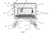
- Figure 4 shows schematically a cross section of a preferred beam delivery system used to obtain BRAGG spectra at small angles.
- Other beam delivery systems can also be used in the present invention, including those disclosed by Kratky, et al. in Austrian Patent No. 2003753 and Harding in U.S. Patent No. 5,265,144.
- the preferred system depicted in Figure 4 further includes a transmission detector.
- a beam delivery system separates the photon radiation emitted by the focus 400 of the X-ray source 404 into a plurality of beams.
- a beam 401 is formed by passing through apertures 410 and is directly detected by detectors 402, which are within the beam's direct line-of sight. These beams are referred to as transmission beams. Scatter interactions are detected by blocking direct line-of-sight detection through the use of ring apertures 410, 411 and exposing the associated detector 420 only to scattered radiation 492. Therefore, scatter radiation, generated when certain beams interact with an inspection region or volume 445, can be detected in the same apparatus as transmission radiation.
- the choice of ring aperture diameters, distance to focus, and distance to detector determines the effective scatter angle 430 of the photons falling on the detector.
- the scatter angle 430 is approximately the same for substantially all photons detected by the detector of the scattered radiation. It is preferred to configure the beam delivery system to establish an effective scatter angle of between two and 8 degrees. It is more preferable to have a scatter angle at or about 3 degrees.
- Using a beam delivery system having a circular symmetry has the advantage of obtaining a scatter contribution from a larger volume of the material being inspected, thereby increasing the inherently weak scatter signal. Additionally, the scatter spectrum can be cost efficiently detected using only a single detector channel 420 with an entrance aperture in the shape of a hole 421.
- the scatter signal is generated by positioning the target region 445, identified in the first stage scan, between the beam forming apertures, irradiating that region 445 using the conical beam 442, and making sure scatter radiation from the target region 445can be detected by the scatter detector.
- the target region 445 often contained within a container 450, is in the shape of a tube or ring 445 and is referred to as the inspection volume or inspection region.
- the length, diameter, and wall thickness of the inspection volume depends on the particular shape of the elements of the beam delivery system, including focus size, ring aperture diameter and width, detector opening and overall distance. In a preferred embodiment for the inspection of large luggage, the inspection volume is at or about 60 cubic centimeters.
- the components of the beam delivery system are mounted to the open ends of a rigid support structure 500 formed in the shape of a C (referred to herein as a C-arm) and aligned with a tolerance of at or about 0.1 millimeters.
- a first arm of the C-arm comprises a X-ray tube with X-ray focus 172, a beam limiting aperture hole mounted to the tube head 401, and a ring-shaped aperture 410.
- a second arm holds comprises a transmission detector array 402, a second ring aperture 411, and an energy dispersive detector 420, equipped with an aperture hole.
- the energy dispersive detector 420 is positioned to receive scattered radiation from a target object placed on the conveyor running between the arms of the C-arm support structure where a first arm is above the conveyor and a second arm is below the conveyor.
- the transmission detector is positioned to receive radiation attenuated by the same target object. It is preferable for the C-arm to be mobile and capable of moving in the x-direction along the length of the conveyor. Therefore, the C-arm with tube and detectors can be re-positioned along the length of the conveyor.
- the scatter detector 420 is comprised of cadmium telluride or cadmium zinc telluride and is operated at room temperature, or approximate to room temperature,
- An exemplary embodiment is available from the e-V Products Company, Saxonburg, Pennsylvania. This type of detector has a spectral resolution performance that is well matched to the limited angular requirements of this application, and therefore the limited spectral resolution of the beam delivery system.
- the potential threat locations inside a container are found automatically by the first stage, and, based upon the physical coordinates obtained through triangulation, the second stage scanning system is automatically positioned to generate an inspection region that substantially overlaps with the identified target region. Where multiple threat locations are identified, the second stage scanning system is sequentially repositioned to focus on each subsequent target region. To scan each target region, the second stage X-ray source is activated and the scatter detector and transmission detector are sampled simultaneously.
- a transmission spectrum associated with the detected transmission data is characterized using a look up reference, figure, table, or chart, and the scatter spectrum is normalized using that identified transmission spectrum.
- an operator actively identifies images that he or she believes corresponds to a potential threat.
- X-ray images from the first inspection stage are displayed to the operator, and the operator points to a suspicious object as it appears in both views.
- operators use a computer system, comprising a mouse and monitor, to position cross hairs over the areas of interest on each of the images.
- the second stage scanning system uses coordinate data generated through triangulation, to position itself such that an inspection region overlaps with the target region, activates the X-ray source and simultaneously samples the scatter detector and transmission detector.
- a transmission spectrum associated with the detected transmission data is characterized using a look up reference, figure, table, or chart, and the scatter spectrum is normalized using that identified transmission spectrum.
- a transmission detector is integrally formed with the beam delivery system, as shown in Figures 4 and 5.
- a preferred transmission detector comprises a 16 channel array of dual energy detectors.
- the detector array further comprises pairs of detectors, including a low energy channel that receives and measures a first amount of radiation first (low energy) and a high energy channel that receives and measures a substantial portion of the balance of radiation (high energy). Dual energy detection has been described in connection with the linear scan arrays of the first inspection stage and is known to persons of ordinary skill in the art.
- the low energy and high energy detectors measure a plurality of low energy and high energy values that can be used to characterize the material being scanned.
- low energy and high energy data are used to reference a look up reference, figure, table, or chart (referred to as a look up source) which contains transmission spectra arranged in accordance with corresponding high and low energy values.
- the look up source is constructed with high energy values on one axis (i.e. the x-axis), and low energy values on a second axis (i.e. the y-axis).
- a look up source 600 is shown.
- the source 600 is a graph with high energy values on the x-axis 605 and low energy values on the y-axis 610. Points 615 corresponding to measured spectra 620 are positioned on the graph according to certain linear combinations of the measured high and low dual energy detector signals on the x and y axis.
- the transmission spectra used to normalize scatter data is therefore identified by obtaining high energy and low energy data values, identifying the point on the graph corresponding to the detected high and low energy values, and looking up the spectrum associated with that point.
- a corresponding transmission spectra 645 can be calculated by performing a two-dimensional interpolation of the spectra 640, 620 associated with the pre-established points 635, 615.
- an exemplary approach places various materials of known composition and thickness, exposes them to X-ray sources, measures the resulting high and low energy data values, and uses the scatter detector to measure the corresponding transmission spectrum. More specifically, the beam path of the beam delivery system is modified to allow a direct beam from the focus through the pinhole to fall on the energy dispersive scatter detector. To further reduce the photon flux into a range that can be tolerated for energy-dispersive measurement, the current of the X-ray source is preferably reduced by a large factor, e.g. 100. Under these parameters, the scatter detector can be used to measure the transmission spectrum. Materials of known composition and thickness are placed in the beam path. The materials are exposed to X-ray radiation.
- Dual energy measurements are made using the dual energy detectors and a transmission spectrum is obtained using the scatter detector.
- a transmission spectrum is obtained and correlated with discrete pairs of dual energy transmission detector readings. This information is then arranged on a chart with the high energy value of the dual energy detector measurement on the x-axis, and the low energy value on the y-axis.
- the spectra are the looked-up objects of the look up source.
- the look up source can alternatively consist of spectral attenuation functions related to the attenuation of the materials placed in the beam when the look up source is being generated.
- the spectrum can then be obtained by multiplying one fixed spectrum, for example the spectrum measured without the material placed into the beam, with the spectral attenuation function retrieved from the look up source.
- the look-up source can contain numbers that are the parameters of analytical expressions, e.g. polynomials, which are formed to describe the attenuation functions in a parametric way.
- the presently described approach is preferred because it enables the construction of a transmission detector array from lower cost materials, as opposed to constructing the array using more expensive energy dispersive detectors and support electronics. Moreover, it also addresses the difficult problem of using energy dispersive detectors to measure transmission spectra at the high flux rates that are experienced at the location of the transmission detector in the given configuration and at the same time at which the scatter data are recorded. The required strong attenuation of the transmission beams is a difficult problem that is avoided using the present invention.
- the look up table is an important element because the preferred dual energy detectors used in the transmission detector cannot deliver spectra directly.
- transmission spectra are being used to correct the scatter spectra that are being recorded by the energy dispersive detector. Normalizing scatter spectra with transmission spectra corrects for the confounding effects introduced by the specific spectral distribution of the primary radiation, as emitted from the X-ray source, as well as by spectrum-distorting effects known as beam hardening. To correct the scatter spectra, the detected scatter spectra are divided by the looked-up transmission spectra.
- a normalized scatter spectrum exhibits a plurality of features.
- a first feature is that the location of the peaks and valleys of the spectrum are determined by the molecular structure of the materials located in the probe region.
- a second unrelated feature is that the average spectral signal of the normalized scatter signal, which can be of varying intensity, is linearly related to the gravimetric density of the material in the probe region. This can be used for threat discrimination since most explosives, particularly military explosives, have a density range above that of most other plastic or food items in suitcases.
- the normalized scatter signal is used to identify a threat item by comparing the obtained normalized scatter spectrum and/or spectral signal with a library of scatter signals from known threat items. This comparison can occur automatically by using a processor to compare a library of threat items, stored in a memory, with the obtained scatter signals. Such a library is developed by measuring the normalized scatter signatures of known threat items.
- the transmission detector can function in a plurality of other ways. In one embodiment, the transmission detector acts as a position sensor. The transmission beam is interrupted or attenuated momentarily when an object on the conveyor crosses it. Tracking the moment of interruption can provide information on the physical position of the container on the conveyor and be used to appropriately position the beam delivery system or container.
- the transmission detector array functions as an imaging detector to provide precise attenuation data for certain areas in containers, like container wall areas, where contraband can be hidden.
- the circular beam is centered on an edge of a container, the edge of the container can be imaged in good detail, and can help analyze the edges for concealed threats.
- transmission detector measurements can be used to determine whether the inspection region is, in fact, the same target region previously identified in the first stage scan. If the transmission data correlates with X-ray characteristics different than those obtained in the first stage scan, the relative positioning of the second stage scanning system and the object under inspection may be modified until the transmission data correlates with the same material characteristics that was identified in the first stage scan.
- transmission detector data are also being used to simplify the algorithm-training procedure of the system, as described below, in particular the collection of threat material properties with irregularly shaped threat samples, like sticks of dynamite.
- the second stage scanning system positions an inspection region to physically coincide with the target region identified in the first stage scan.
- the positioning means may be achieved using any method known in the art.
- a plurality of control commands is produced in response to the determination of the location of the target region.
- the control commands are generated by at least one processor in data communication with a plurality of processors capable of executing the aforementioned triangulation techniques and/or determining the intersection of projection lines to identify the location of the target region in three dimensional system coordinates.
- the control commands comprise data signals that drive a three-axis control system.
- the vertical position of the second-stage inspection volume can be adjusted to the target volume or region of the first stage scan by moving the conveyor system up or down.
- the control commands comprise data signals that drive the adjustment of the beam delivery system in the second stage scanning system.
- the beam delivery system adjustment can include any type of adjustment to the collimation or beam focus, including the physical movement of a plurality of apertures horizontally, vertically, or diagonally, the physical modification of the diameter of the ring aperture by, for example, increasing or decreasing the aperture size.
- the position of the support structure, or C-arm can be modified along the conveyor direction to appropriately position the beam delivery system.
- the second stage scan may be compromised when the volume of the target region is smaller than the inspection region of the second stage.
- extraneous material other than the material identified as being a potential threat, such as air, metal, or container edges, may be included.
- the resulting scatter radiation is therefore a function of multiple material types and may not be readily identifiable as being the signature of a single substance.
- the present invention comprises a threat recognition process that incorporates a training methodology which relies on libraries in which threat signatures are obtained by combining the threat with other common materials, such as clothing, plastic, air, and metals.
- the data used in training and developing the detection process are chosen to include data, which are corrupted by errors based on partial volume data from statistically varying containers and threat and non-threat material combinations.
- a combination signal will be detected by the second scanning stage.
- the automatic threat recognition methodology recognizes the threat from the combination signal based upon the aforementioned training.
- An exemplary automatic threat recognition methodology, based on neural networks, is described below.
- the detected scatter data is corrected for the effects of extraneous materials by preprocessing the data.
- the motion control system tracks where the inspection volume or region is located in relative to a specific reference point, such as the approximate outlines of the container, and relative to the conveyor system. Because of the ability to measure and track these reference points, the amount and portion of the inspection volume occupied by the conveyor structure can be determined.
- the conveyor structure includes the belt material as well as the structural member that is underneath the conveyor, which is referred to as the slider bed.
- the scatter spectrum of the conveyor materials is measured and stored in a reference database.
- the scatter spectrum is corrected by multiplying the conveyor material scatter spectrum by a weighting factor to account for the size of the inspection volume occupied and that amount is subtracted from the measurement.
- Optical detectors such as a plurality of light-curtains, can be positioned across and within the scanning system to generate control signals that convey information about the height and edges of the container relative to the conveyor system and relative to the inspection region. It therefore can be calculated which portion of the inspection region is filled with air.
- transmission values for the scatter beam are measured by an array detector.
- An exemplary array comprises 16 channels and yields transmission data for 16 subdivisions within the inspection volume.
- the transmission values can be used to characterize the material distribution in the inspection volume. Based on these transmission values, approximate mass values can be determined for masses contained in each of the 16 subdivisions. For example, where the transmission detector value returns a value indicating the subdivision has material with zero thickness, it can be assumed that the subdivision is occupied by air.
- the inspection volume is subdivided.
- system resolution is increased by providing multiple energy dispersive detectors, such as 2, 3, 4, 5, 6 or more, in place of a single energy dispersive detector as shown in Figure 4.
- a schematic representation of the beam delivery system of Figure 4 780 is shown relative to a beam delivery system having multiple energy dispersive detectors 785.
- a first system 780 comprises single detector 700s, circular aperture 701s, inspection volume 702s, circular aperture 703s, and X-ray focus 704s.
- the dark areas represent the presence of radiation blocking material, e.g. 1/4inch lead alloy, and the white areas represent areas that are transparent to X-rays above 30 keV.
- a second system 785 comprises an X-ray focus 704q, circular aperture 703q, divided inspection volume 702q, detector side beam shaping aperture 701q, and quadruple detector 700q.
- the aperture 701q is center-symmetric and consists of four slits, each conforming to part of a circle.
- the centers of the circular slits are chosen to be of the same pattern as the detectors of the quadruple detector 700q. For example, if the detector cluster consists of four channels centered on the four corners of a 2 by 2 mm square, the centers of the partial and circular apertures lay on a circle with diameter equal to the square root of 2 times 2mm.
- the resulting inspection region for each individual detection region is about one quarter of the full inspection volume. A subdivided inspection region provides a higher spatial resolution of the second stage inspection. Clusters of energy dispersive detectors with their supporting electronics are commercially available from companies such as eV Products, Saxonburg, Pennsylvania.
- a collimating system of vanes can be placed in front of the detector cluster orthogonal to the surface of the detector and in line with the plane of separation between each detector.
- a separator 705 diffracted radiation is more effectively limited to reach the appropriate channel in the cluster and, consequently, detected signals are more readily associated with materials from specific areas within the inspection region.
- the separator 705 extends from the surface of the detector cluster toward the surface of the adjacent aperture.
- the number of separator vanes is dependent on the number of detectors.
- a typical vane material and thickness is lead alloy of 0.5 mm thickness.
- a container enters into the first stage scan 905 where it is exposed to a plurality of projected beams 915. From that exposure, X-ray characteristics are determined 920 and target regions containing potential threats are identified 925, 935. If no potential threats are identified, the container is not subjected to a second scanning stage 940. The three dimensional coordinates of the target region is determined 945 and, accordingly, the inspection region generated by the second stage scanning system is coordinated to coincide with the target region 950. The inspection region is subjected to X-ray radiation in order to obtain transmission and spectral data 955. The spectral data is then analyzed 960 to determine the existence of a threat.
- the data collected in the second stage scan comprises both localized dual energy transmission data and localized BRAGG diffraction spectra, which are subject to statistical variances, originating from photon signal fluctuations, partial volume limitations, or variations of the type of luggage and their contents, among other causes.
- the automatic threat resolution is performed by a probabilistic technique in which a plurality of input data points, obtained from the raw spectral scan data, contribute to the probability that the corresponding spectrum belongs to a particular class of threat or non-threat items.
- a probabilistic technique relies on the plurality of input data points as a whole rather than on individual data points.
- probabilistic classification techniques can include explicit, identifiable rules created by a programmer
- the preferred techniques utilize a classification procedure that incorporates the results of training.
- the classification algorithm can be used to process a training set consisting of patterns for structures of known classification. The results of this processing are used to adjust the algorithm, so that the classification accuracy improves as the algorithm learns by processing the training sets.
- trainable classifier One type of trainable classifier that can be employed is an artificial neural network.
- Artificial neural networks attempt to model human biological neural networks to perform pattern recognition and data classification tasks.
- Neural networks are fine grain parallel processing architectures composed of non-linear processing units, known as neurons or nodes, which attempt to replicate the synaptic-dendritic interconnections found in the human brain.
- a feed forward network passes a signal by links from input nodes to output nodes, in one direction only.
- the nodes are organized into multiple layers: the input layer, output layer, and several "hidden layers" in between. The adjacent layers are normally fully interconnected.
- Figure 8 depicts a schematic representation of a preferred type of artificial neural network 800 known as a hidden-layer feed-forward network consisting of an input layer 810 of neurons or nodes, at least one hidden layer 820, and an output layer 830.
- the neuron layers are linked via a set of synaptic interconnections.
- Each neuron in the input layer is typically connected to each neuron in the hidden layer, and each neuron in the hidden layer is typically connected to each neuron in the output layer, via a synaptic connection; these may be physical, electronic connections, or they may be embodied in software, as may be the neurons themselves, which software operates on conventional digital computers.
- the neurons or nodes typically accept several inputs and create a weighted sum (a vector dot product). This sum is then tested against an activation rule (typically a threshold) and then processed through an output function.
- the output function could be a non-linear function such as a hard-limiter; a sigmoid function; a sine-function or any other suitable function known to a person of ordinary skill in the art.
- the threshold determines how high the input to that neuron must be in order to generate a positive output of that neuron.
- a neuron may be considered to be turned on, for instance, whenever its value is above a predetermined value such as, for instance, 0.9 and turned off with a value of less than another value such as 0.1, and has an undefined "maybe" state between those values.
- the connectivity pattern defines which node receives the output value of a previous node as their input.
- the connection between two neurons is realized in mathematical terms by multiplying the output of the lower level neuron by the strength of that connection (weight).
- the values for the inputs define an activity state.
- the initial activity state is defined upon presentation of the inputs to the network.
- the output response of any hidden layer neuron (o j ) and any output layer neuron is a function of the network input to that neuron defined by the difference of that neuron's threshold ( ⁇ ) and the input to it.
- i and j represent neurons of two different layers with j representing the higher layer; ⁇ j represents the bias value for j layer neuron; and w ji represents the strength of the connection between neuron i and neuron j.
- sine-type functions or any other suitable function known in the art, may be used to obtain the desired type of response function for the output of a neuron.
- the weights are chosen so as to minimize the error between the produced result and the correct result.
- a learning rule defines how to choose the weight values. Several commonly used learning rules are back- propagation, competitive learning, adaptive resonance, and self-organization.
- the artificial neural network uses back-propagation learning.
- the back-propagation learning algorithm derived from the chain rule for partial derivatives, provides a gradient descent learning method in the space of weights and can be further understood by reference to D. E. Rumelhart, et al., Parallel Distributed Processing, ch. 8, pp. 322-28 (MIT Press, 1986) and Haykin, Simon (1999), "Neural Networks", Prentice Hall, both of which are incorporated herein by reference.
- Back-propagation learning involves a set of pairs of input and output vectors.
- the network uses an input vector to generate its own, or actual, output vector.
- the actual output vector is compared with a desired output, or target, vector that may be defined usually in the course of training.
- the weights are changed to obtain a match between the target vector and the actual output vector.
- the conventional delta rule may be used for this calculation where the weight for a particular synapse or connection between units is adjusted proportionally to the product of an error signal, delta, available to the unit receiving input via the connection and the output of the unit sending a signal via the connection. If a unit is an output unit, the error signal is proportional to the difference between the actual and target value of the unit. If it is a hidden layer, it is determined recursively in terms of the error signals of the units to which it directly connects and the weights of those connections.
- the training of a neural network is the process of setting the connection weights so that the network produces a desired output in response to any input that is normal for the situation.
- a supervised training refers to the kind of training that requires a training set, i.e. a set of input-output patterns.
- the back-propagation algorithm is an efficient technique to train a feed-forward network. It operates to send an error back through the network during the training process, thereby adjusting all the link weights in correspondence with their contribution to the error. The weights of the network therefore gradually drift to a better set of values.
- the initial weights are chosen randomly within reasonable limits and adjustments are left to the training process.
- the artificial neural network 800 is trained on a suitably large set of threat and non-threat X-ray raw scan data, to generate an output 840, in accordance with the error back-propagation learning method described above.
- the required set of threat and non-threat raw scan data for training can be obtained either from the scanning system of the first stage or the scanning system of the second stage or both depending upon whether artificial neural networks are used to process scan data from the first stage or the second stage or from both the stages.
- the 'scan data' 805 to be used to train the neural net 800 may comprise of raw attenuation data, raw transmission photon counts, raw diffraction photon spectra or any other data known to a person of ordinary skill in the art.
- the purpose of the neural network processing step is to have a processing means capable of recognizing a threat signature.
- a threat signature is defined as a spectrum, i.e. an array of numbers corresponding, on a one-to-one basis, to the discretized values of a physical quantity, such as the energy of X-rays, and includes unrelated, but relevant, other values, such as transmission detector array data, bag height, and other environmental factors.
- the spectrum may consist of any amount of data points, the present invention preferably operates on a spectrum data set of between 200 and 800 points and, more preferably, of approximately 500 points.
- the network may consist of any number of layers, it is preferred that it consists of four layers, including one input layer, two hidden layers, and one output layer.
- the network can have multiple output nodes with various indicators, it is preferred that, for the present invention, the network comprise a single node the output of which may be interpreted as either "yes, a threat has been recognized” or "no, a threat has not been recognized”.
- the raw diffraction spectrum data from the second stage is used to generate the required set of threat and non-threat scan data for training.
- These spectral counts represent raw, that is non-normalized, scan data 805 that is subsequently used to train the neural network 800.
- this scan data 805 may be further processed to generate a plurality of normalized data.
- the scanning process is repeated to obtain scan data of a sufficiently large number of containers containing threat and non-threat items packaged in a variety of permutations and combinations to model real-world scenarios.
- This raw scan data referred to hereinafter as training data
- This raw scan data comprise an input-set to be used for training the neural network.
- each output training data maybe further tagged to identify whether the respective training data represents a defined/known threat or non-threat item.
- This output training data maybe further stored in a suitable library or database such as a file server on a digital computer system along with the tagged identification information.
- the library or database of training data may be enhanced to incorporate and reflect all previously known threat materials and their corresponding raw 'scan data'.
- two libraries are generated.
- a first library has signatures of threats.
- a larger second library has signatures of innocuous, or non-threat, items.
- the training process utilizes the threat and non-threat signatures to introduce into the system threat-like and non-threat-like signatures.
- a threat-like signature is a linear combination of a sample from the threat library with a plurality of samples, such as two, from the non-threat library.
- the coefficients of the mix are randomly simulated.
- a simulated white noise is also added to the generated mixture, with its amplitude also randomly generated, within an interval from zero to a given fraction of the signal.
- a non-threat-like signature is a mixture of a plurality of non-threat signatures, such as two or three.
- the coefficients of the mix are randomly simulated.
- a simulated white noise is also added to the generated mixture, with its amplitude also randomly generated, within an interval from zero to a given fraction of the signal.
- Figure 10 depicts a plurality of steps, in flow diagram format, of one embodiment of the back-propagation training process of the invention.
- processing is conducted using a computer having a plurality of processors for executing the analytical processes described herein, embodied in at least one software program, a plurality of storage devices for storing the requisite data, library information, and other information necessary to conduct these analyses, and an output device, such as monitor, among other commonly known computing devices and peripherals.
- the synaptic weights and thresholds of the neural net are initialized 1005 with, for example, random numbers.
- the input layer of the neural network is introduced 1010 to a first set of training data and the net is run to receive 1015 an actual output.
- the neural net makes use of the randomly assigned weights and thresholds to generate an output on the basis of a suitable resolving function such as a sigmoid-type Fermi equation (described earlier), a sine function or any other function known to a person of ordinary skill in the art.
- the output could be in the form of differentiable signals such as numerals between, say, 0 and 1, in the form of positive or negative states implied by an output numeral of greater than or less than 0 respectively, or any other suitable indication as evident to a person of ordinary skill in the art.
- the first set of training data is introduced into the system and, based on the random weights and thresholds, produces an output 'x', i.e. a numeral greater than 0. If the training data represents a threat, this output indication is set as a benchmark to identify a 'threat' while a numeral less than 0 maybe set to identify a 'non-threat' item. Once a suitable benchmark is set, the training process is repeated with the next set of training data and corresponding actual outputs are received. The actual output is compared 1020 with the desired output, defined by an operator with knowledge as to whether input data is or is not representative of a threat, for the corresponding set of training data that was fed to the neural net in step 1010.
- a check 1025 is made to see if the neural net has been trained on the entire set of training data. If not then the next set of training data is introduced to the neural net and the foregoing steps are repeated. The training process continues until the neural net has been trained on the entire set of training data.
- the comparison 1020 suggests that the actual output is not in agreement with the desired or targeted output, the ensuing additional steps are performed.
- the difference between the actual and desired outputs is used to generate 1030 an error pattern in accordance with a suitable back-propagation rule such as the 'delta rule' or any other error estimation rule known to a person of ordinary skill in the art.
- the error pattern is used to adjust 1035 the synaptic weights on the output layer such that the error pattern would be reduced the next time if the same set of training data were presented as the inputs.
- the weights of the hidden layers, preceding the output layer are modified 1040 by comparing what outputs they actually produce with the results of neurons/nodes in the output layer to form an error pattern for the hidden layer.
- the error can thus be propagated as far back over as many hidden layers as constituting the neural network.
- the weights for the input layer are similarly educated 1045, and the next set of training data is introduced to the neural network to iterate through the learning cycle again.
- the neural network is therefore trained by presenting each set of training data in turn at the inputs and propagating forwards and backwards, followed by the next input data, and repeating this cycle a sufficient number of times such that the neural network keeps getting closer and closer to the required weight values each time.
- the network through the iterative back-propagation process, establishes a set of weights and thresholds for neural connections so that a desired output pattern is produced for the presented input information.
- the learned information of a neural network is contained in the values of the set of weights and thresholds.
- the neural network is structured such that, through iterative forward and backward propagation, every node in a layer can be made to contribute to every node in a subsequent layer, only certain nodes in a layer maybe used to contribute to certain nodes in a subsequent layer, or every node in a layer contributes to every node in a subsequent layer but the impact of certain first layer nodes on subsequent layers are weighted relative to other first layer nodes.
- the nodes closest to subsequent layer nodes are weighted relative to other nodes in that same layer.
- links between the input layer and the first hidden layer are not chosen randomly, but selected to have a special distribution.
- Each hidden layer node is responsible for a region of the spectrum. Links to each hidden layer node from this region have higher weights. Therefore, the farther an input node is from this region, and the less responsible it is, the weaker the link with that input node. Together, the hidden nodes encompass the entire input layer spectrum.
- multiple networks are formed and trained to identify distinct threats. Therefore, new threat recognition is done by implementing a neural network as a set of multiple networks, each trained to identify a specific threat.
- Each network group is formed and trained to address and recognize one threat.
- the threats T 1 , T 2 , T 3 ...T n
- the groups G 1 , G 2 , G 3 ...G n
- Network group G n is trained to recognize threat T n .
- G n recognizes any other threat, T n-2 , T n-1 , T n+1 , it is not considered relevant.
- G n is trained using threat signatures of T n and a corresponding library of non-threat signatures.
- a group consists of a plurality, such as two, three, or four, completely separate networks, each similarly trained to recognize the same threat.
- Threat recognition is achieved where the average of the recognition results of each network indicates a threat. Where an additional threat is identified, T new , a new group of networks, G new , can be created, without having to retrain or modify all existing groups. This permits the more efficient, incremental addition of new threat recognition networks.
- a system can output a threat alarm if the recognition result, averaged over all network groups, indicates a threat.
- a system can output a threat alarm if only one group of networks indicates a threat or if a subset of network groups indicates a threat.
- threat recognition is effectuated by monitoring the output of substantially all groups of networks. If the recognition result, averaged over all groups, indicates the existence of a threat, the output results of individual network groups are analyzed. If at least two groups indicate the presence of a threat, then the groups are reviewed to determine which threat has been recognized.
- the threshold analysis can be performed even if only a portion of all network groups is monitored and the secondary analysis can be performed if fewer than two groups indicate a threat.
- a plurality of different networks is stored in a storage device in data communication with processors responsible for executing neural network analytical processes.
- Each set of networks has a different level of sensitivity, i.e. least sensitive, less sensitive, normal sensitivity, more sensitive, most sensitive.
- the appropriate network set is loaded into the system.
- a network set having a standard level of sensitivity may be used in operation and a parallel network set, having varying levels of sensitivity, may be concurrently loaded and ready for use, when necessary. Having a parallel network avoids downtime associated with loading new network sets into local memory, or RAM.
- Networks having varying degrees of sensitivity are developed by incorporating a sensitivity variable in the training process.
- a desired level of sensitivity is communicated to an additional input layer node, thereby inherently incorporating it into the training process.
- Every training event could further be associated with a randomly selected sensitivity level, selected from within a reasonable range. Training is therefore conducted with the selected level of sensitivity.
- the embodiment of back-propagation learning process assumes that the training data is first collected by operating the first and/or second scanning systems offline, namely by scanning a large number of baggage containing known threat materials camouflaged amongst non-threat items in a variety of combinations to represent a variety of concealment scenarios.
- the training data so obtained is then used to educate the neural network that can then be used to operate in real-world situations.
- the first and/or second stage systems are online, that is operational at real-world sites such as at airports for luggage inspection, the associated neural network is already partially educated (on the training data obtained through test baggage) to discern threat from non-threat items.
- the neural network need not be taught through the scanning of test baggage prior to running the first and/or second scanning systems online. Instead the first and/or second scanning systems can be operated online and the scan data can then be fed into the neural network in real-time. On the basis of this real-time scan data, the neural net is made to classify threat and non-threat items.
- the scanned image of the baggage is also presented to an operator in the form of a visual display such as on a conventional computer screen, as is known in the art. The operator compares the output of the neural net with his own observation of the scanned baggage.
- the operator prompts the neural net with the correct or desired output, enabling the neural network to adjust its weights and thresholds accordingly.
- the neural network will learn how to identify threat objects. This self-learning process enables the neural network to learn continuously.
- the on-line, self-learning training process does have certain advantages.
- a company or organization that uses the present invention may not want to share or disclose data to third parties due to privacy or security reasons. Therefore, it may be essential to enable self-learning.
- the flow of data may change seasonally depending upon how containers change. Specifically, seasonal variations do occur in airline passenger travel where passenger bags may get larger in the winter to accommodate more clothing or the number of total bags may increase due to larger numbers of people traveling in the summer. To address such seasonal variation, it is more practical to allow on-line autonomous adaptation.
- a standard library may not be as helpful as self-taught systems that automatically learn in accordance with its own unique context. More specifically, over time, a system in the field will be trained on containers that have threat and non-threat items unique to their geographic context. Due to operator training and interaction, a particular system would therefore develop a trained processing system tailored to their geographical context. It is preferred, however, that, irrespective of the geographical location, systems get periodically trained using threats that are new or infrequently seen to ensure that the system does not forget the identity of such threats. This update could be performed by the statistically controlled reinjection of threats from existing threat databases.
- this continuous self-learning process can be used in conjunction or combination with the offline teaching process of the first embodiment, using test baggage.
- the neural network is first trained on scan data obtained by running the X-ray system offline on test baggage and then through operator prompts in real-time operations as well, so that the ability of the neural net, in identifying objects, continuously improves through self-learning. Nevertheless, the system may undergo retraining offline using data from multiple site locations, thereby taking full advantage of the sum total of learning being generated by the operation of multiple systems.
- acquired scan data is fed into the neural network for identification. If the object is identified with a high degree of confidence, the identification and scan image is conveyed to an operator, along with an indication of what the object may be, to enable the operator to take an action, including conducting a hand search, questioning the container owner, permitting the container to pass, or calling in additional personnel.
- the operator provides feedback to the system based upon the identity of the threat/non-threat and action taken. For example, if the system identifies the existence of a threat, the operator can check the container to determine if a threat exists and then inform the system whether it was or was not correct.
- the neural network increases its confidence factor for that object's scan data and stores the scan data in a suitable database as an exemplar for retraining. If incorrect, the neural network implements the error back-propagation process to suitably adjust its weights and thresholds and stores the scan data in a suitable database as an exemplar for retraining.
- the system utilizes groups of networks, which are accompanied by libraries of threat patterns and innocuous patterns, and that the system is not authorized to modify these libraries. It is further preferred to include an additional library, a buffer-library, that is available for modification based upon incoming data.
- the buffer library comprises incoming new data, and is preferably periodically cleansed of older data. Consequently, the networks are being re-trained using the buffer-library and the two stable libraries, with a proper adaptation time scale.
- Several previous versions of network groups are stored as a back up and a comparison of newly adapted system with its older versions can be conducted and produced in the form of a report. As described, on-site training can be set up as an automatic feature, but operator input may be required in the rare case of a real alarm.
Landscapes
- Physics & Mathematics (AREA)
- General Physics & Mathematics (AREA)
- Analysing Materials By The Use Of Radiation (AREA)
- Life Sciences & Earth Sciences (AREA)
- General Life Sciences & Earth Sciences (AREA)
- Geophysics (AREA)
- High Energy & Nuclear Physics (AREA)
Applications Claiming Priority (2)
| Application Number | Priority Date | Filing Date | Title |
|---|---|---|---|
| US10/662,778 US20050058242A1 (en) | 2003-09-15 | 2003-09-15 | Methods and systems for the rapid detection of concealed objects |
| US662778 | 2003-09-15 |
Publications (2)
| Publication Number | Publication Date |
|---|---|
| EP1526392A2 true EP1526392A2 (fr) | 2005-04-27 |
| EP1526392A3 EP1526392A3 (fr) | 2007-01-24 |
Family
ID=34274205
Family Applications (1)
| Application Number | Title | Priority Date | Filing Date |
|---|---|---|---|
| EP04255584A Withdrawn EP1526392A3 (fr) | 2003-09-15 | 2004-09-15 | Dispositif et procédé pour la détection rapide d'objets cachés |
Country Status (2)
| Country | Link |
|---|---|
| US (6) | US20050058242A1 (fr) |
| EP (1) | EP1526392A3 (fr) |
Cited By (7)
| Publication number | Priority date | Publication date | Assignee | Title |
|---|---|---|---|---|
| GB2516794A (en) * | 2009-12-03 | 2015-02-04 | Rapiscan Systems Inc | Time of flight backscatter imaging system |
| US9123519B2 (en) | 2012-06-01 | 2015-09-01 | Rapiscan Systems, Inc. | Methods and systems for time-of-flight neutron interrogation for material discrimination |
| US9158029B2 (en) | 2013-06-14 | 2015-10-13 | Morpho Detection, Llc | Multi-stage security screening system and smart communication system |
| US9625606B2 (en) | 2009-05-16 | 2017-04-18 | Rapiscan Systems, Inc. | Systems and methods for high-Z threat alarm resolution |
| US9632205B2 (en) | 2011-02-08 | 2017-04-25 | Rapiscan Systems, Inc. | Covert surveillance using multi-modality sensing |
| US9791590B2 (en) | 2013-01-31 | 2017-10-17 | Rapiscan Systems, Inc. | Portable security inspection system |
| US11796489B2 (en) | 2021-02-23 | 2023-10-24 | Rapiscan Systems, Inc. | Systems and methods for eliminating cross-talk signals in one or more scanning systems having multiple X-ray sources |
Families Citing this family (176)
| Publication number | Priority date | Publication date | Assignee | Title |
|---|---|---|---|---|
| US9958569B2 (en) | 2002-07-23 | 2018-05-01 | Rapiscan Systems, Inc. | Mobile imaging system and method for detection of contraband |
| US7963695B2 (en) | 2002-07-23 | 2011-06-21 | Rapiscan Systems, Inc. | Rotatable boom cargo scanning system |
| GB0812864D0 (en) | 2008-07-15 | 2008-08-20 | Cxr Ltd | Coolign anode |
| US10483077B2 (en) | 2003-04-25 | 2019-11-19 | Rapiscan Systems, Inc. | X-ray sources having reduced electron scattering |
| US9208988B2 (en) | 2005-10-25 | 2015-12-08 | Rapiscan Systems, Inc. | Graphite backscattered electron shield for use in an X-ray tube |
| US20050058242A1 (en) | 2003-09-15 | 2005-03-17 | Peschmann Kristian R. | Methods and systems for the rapid detection of concealed objects |
| US8837669B2 (en) | 2003-04-25 | 2014-09-16 | Rapiscan Systems, Inc. | X-ray scanning system |
| US8223919B2 (en) | 2003-04-25 | 2012-07-17 | Rapiscan Systems, Inc. | X-ray tomographic inspection systems for the identification of specific target items |
| US9113839B2 (en) | 2003-04-25 | 2015-08-25 | Rapiscon Systems, Inc. | X-ray inspection system and method |
| US7949101B2 (en) | 2005-12-16 | 2011-05-24 | Rapiscan Systems, Inc. | X-ray scanners and X-ray sources therefor |
| US8243876B2 (en) | 2003-04-25 | 2012-08-14 | Rapiscan Systems, Inc. | X-ray scanners |
| US8451974B2 (en) * | 2003-04-25 | 2013-05-28 | Rapiscan Systems, Inc. | X-ray tomographic inspection system for the identification of specific target items |
| GB0525593D0 (en) * | 2005-12-16 | 2006-01-25 | Cxr Ltd | X-ray tomography inspection systems |
| US7856081B2 (en) | 2003-09-15 | 2010-12-21 | Rapiscan Systems, Inc. | Methods and systems for rapid detection of concealed objects using fluorescence |
| US7672431B2 (en) * | 2003-10-10 | 2010-03-02 | Bayer Schering Pharma Aktiengesellschaft | X-ray arrangement and x-ray contrast process for imaging an object under examination that contains at least one radiopaque element as well as use of the x-ray arrangement |
| US7383261B2 (en) * | 2004-01-16 | 2008-06-03 | Xerox Corporation | Reference database and method for determining spectra using measurements from an LED color sensor, and method of generating a reference database |
| WO2006085904A2 (fr) * | 2004-05-27 | 2006-08-17 | L-3 Communications Security And Detection Systems, Inc. | Procedes et appareil de detection d'articles de contrebande utilisant un rayonnement terahertz |
| JP4459738B2 (ja) * | 2004-07-05 | 2010-04-28 | 株式会社エヌ・ティ・ティ・ドコモ | 中継装置、通信装置および指向性制御方法 |
| US20080063140A1 (en) * | 2004-07-20 | 2008-03-13 | William Awad | System and Method for Detecting the Presence of a Threat in a Package |
| GB0420224D0 (en) * | 2004-09-11 | 2004-10-13 | Koninkl Philips Electronics Nv | Coherent scatter imaging |
| US7813540B1 (en) * | 2005-01-13 | 2010-10-12 | Oro Grande Technologies Llc | System and method for detecting nuclear material in shipping containers |
| DE102005016656A1 (de) * | 2005-01-26 | 2006-08-10 | Smiths Heimann Gmbh | Kollimator mit einstellbarer Brennweite |
| US8643503B2 (en) | 2005-01-28 | 2014-02-04 | Kirill Mostov | Transportation security system and associated methods |
| US7990270B2 (en) * | 2005-01-28 | 2011-08-02 | Kirsen Technologies Corporation Inc. | Transportation security system and associated methods |
| WO2006081615A1 (fr) * | 2005-02-01 | 2006-08-10 | Qrsciences Pty Ltd | Procede et appareil permettant de detecter des volumes importants blindes |
| JP2008530844A (ja) * | 2005-02-07 | 2008-08-07 | エヌエックスピー ビー ヴィ | Rfidシステム、rfidシステムを有するゲート配置およびトランスポンダの検出方法 |
| US7991242B2 (en) | 2005-05-11 | 2011-08-02 | Optosecurity Inc. | Apparatus, method and system for screening receptacles and persons, having image distortion correction functionality |
| CA2608119A1 (fr) | 2005-05-11 | 2006-11-16 | Optosecurity Inc. | Procede et systeme d'inspection de bagages, de conteneurs de fret ou de personnes |
| US20070041613A1 (en) * | 2005-05-11 | 2007-02-22 | Luc Perron | Database of target objects suitable for use in screening receptacles or people and method and apparatus for generating same |
| US7653176B2 (en) * | 2005-06-14 | 2010-01-26 | L-3 Communications Security and Detection Systems Inc. | Inspection system with material identification |
| WO2006138521A2 (fr) * | 2005-06-16 | 2006-12-28 | Ii-Vi Incorporated | Systeme d'imagerie par diffusion de photons et analyse de l'energie |
| US7428297B2 (en) * | 2005-07-05 | 2008-09-23 | L-3 Communications Security And Detection Systems, Inc. | Methods and apparatus for e-beam scanning |
| US7733287B2 (en) * | 2005-07-29 | 2010-06-08 | Sony Corporation | Systems and methods for high frequency parallel transmissions |
| EP1934586A2 (fr) * | 2005-10-06 | 2008-06-25 | Philips Intellectual Property & Standards GmbH | Optimisation des parametres d'acquisition pour tomographie par diffusion coherente assistee par ordinateur |
| US9046465B2 (en) | 2011-02-24 | 2015-06-02 | Rapiscan Systems, Inc. | Optimization of the source firing pattern for X-ray scanning systems |
| US7657092B2 (en) * | 2005-11-30 | 2010-02-02 | Iscon Video Imaging, Inc. | Methods and systems for detecting concealed objects |
| US7664324B2 (en) * | 2005-11-30 | 2010-02-16 | Iscon Video Imaging, Inc. | Methods and systems for detecting concealed objects |
| US8451162B2 (en) * | 2005-12-20 | 2013-05-28 | Walleye Technologies, Inc. | Microwave datum tool |
| ITFI20060098A1 (it) * | 2006-04-28 | 2007-10-29 | Saima Sicurezza Spa | Dispositivo portatile per la rilevazione di oggetti nascosti |
| CN101071110B (zh) | 2006-05-08 | 2011-05-11 | 清华大学 | 一种基于螺旋扫描立体成像的货物安全检查方法 |
| US7899232B2 (en) | 2006-05-11 | 2011-03-01 | Optosecurity Inc. | Method and apparatus for providing threat image projection (TIP) in a luggage screening system, and luggage screening system implementing same |
| CN101473239A (zh) * | 2006-06-22 | 2009-07-01 | 皇家飞利浦电子股份有限公司 | 集成在扫描器孔壁上的磁共振接收线圈阵列 |
| US8494210B2 (en) | 2007-03-30 | 2013-07-23 | Optosecurity Inc. | User interface for use in security screening providing image enhancement capabilities and apparatus for implementing same |
| EP2049918B1 (fr) * | 2006-08-01 | 2018-01-17 | Koninklijke Philips N.V. | Tomographie informatisée avec tube stéréo |
| WO2008034232A1 (fr) | 2006-09-18 | 2008-03-27 | Optosecurity Inc. | Procédé et appareil d'évaluation de caractéristiques de liquides |
| CA2651728C (fr) * | 2006-10-02 | 2012-04-17 | Optosecurity Inc. | Plateau pouvant servir a la determination du statut de menace d'un objet a un point de controle de la securite |
| CN101162205B (zh) * | 2006-10-13 | 2010-09-01 | 同方威视技术股份有限公司 | 对移动目标进行检查的设备及避让方法 |
| WO2008140498A1 (fr) * | 2006-11-28 | 2008-11-20 | Williams Colin P | Technique de tomographie gravitationnelle pour déterminer une distribution de masse |
| WO2008070788A2 (fr) * | 2006-12-06 | 2008-06-12 | Kirsen Technologies Corporation | Système et procédé pour détecter des objets et des substances dangereux |
| NL1033178C2 (nl) * | 2007-01-05 | 2008-07-11 | Scarabee Id B V | Bagage-afgiftesysteem. |
| US8094874B2 (en) * | 2007-05-29 | 2012-01-10 | Lockheed Martin Corporation | Material context analysis |
| US8306272B2 (en) * | 2007-05-31 | 2012-11-06 | Microsemi Corporation | Method and system for dynamically altering the analysis methodology of millimeter wave imagery in response to the range and direction of motion of a subject |
| WO2009043145A1 (fr) * | 2007-10-01 | 2009-04-09 | Optosecurity Inc. | Procédé et dispositifs pour estimer l'état de menace d'un article à un point de contrôle de sécurité |
| CN101849178B (zh) * | 2007-10-03 | 2014-03-05 | 联邦科学与工业研究组织 | 线上能量分散x射线衍射分析仪 |
| US8115472B2 (en) * | 2007-10-24 | 2012-02-14 | Kirsen Technologies Corporation Inc. | System and method for space control and remote monitoring |
| WO2009120243A2 (fr) * | 2007-12-06 | 2009-10-01 | Nextgen, Inc. | Détection d’explosifs à distance à base d’orbitron |
| US20100282960A1 (en) * | 2007-12-26 | 2010-11-11 | Clark Keith A | Combined imaging and trace-detection inspection system and method |
| US20090168958A1 (en) * | 2008-01-02 | 2009-07-02 | Cristina Francesca Cozzini | Apparatus and method for identifying components in a container |
| WO2009094042A1 (fr) * | 2008-01-25 | 2009-07-30 | Analogic Corporation | Combinaison d'images |
| US7768444B1 (en) * | 2008-01-29 | 2010-08-03 | Rourk Christopher J | Weapon detection and elimination system |
| WO2010009264A1 (fr) * | 2008-07-16 | 2010-01-21 | Boris Oreper | Système d’irradiation comprenant un dispositif de balayage à faisceau d’électrons |
| CN101647706B (zh) * | 2008-08-13 | 2012-05-30 | 清华大学 | 高能双能ct系统的图象重建方法 |
| US8111808B1 (en) | 2008-08-15 | 2012-02-07 | Lockheed Martin Corporation | X-ray explosive imager |
| US20100046707A1 (en) * | 2008-08-20 | 2010-02-25 | Geoffrey Harding | Xrd screening system and method |
| US8867816B2 (en) | 2008-09-05 | 2014-10-21 | Optosecurity Inc. | Method and system for performing X-ray inspection of a liquid product at a security checkpoint |
| WO2010028474A1 (fr) * | 2008-09-15 | 2010-03-18 | Optosecurity Inc. | Procédé et appareil d’évaluation des propriétés de liquides par rayons x |
| US8229228B2 (en) * | 2008-09-16 | 2012-07-24 | Robert Bosch Gmbh | Image analysis using a pre-calibrated pattern of radiation |
| US8090150B2 (en) * | 2008-10-10 | 2012-01-03 | Morpho Detection, Inc. | Method and system for identifying a containment vessel |
| US8433037B1 (en) | 2008-10-23 | 2013-04-30 | Lockheed Martin Corp | X-ray radar |
| US8411820B1 (en) | 2008-10-23 | 2013-04-02 | Lockheed Martin Corp. | 3D x-ray microscopy imaging system |
| US8411821B1 (en) | 2008-10-23 | 2013-04-02 | Lockheed Martin Corp. | 3D X-ray reflection microscopy imaging system |
| US7856083B2 (en) * | 2008-10-31 | 2010-12-21 | Morpho Detection, Inc. | System and method to account for cross-talk among coherent scatter detectors |
| US8189860B2 (en) * | 2008-11-07 | 2012-05-29 | Micro Usa, Inc. | Systems and methods of using spatial/spectral/temporal imaging for hidden or buried explosive detection |
| GB0901338D0 (en) | 2009-01-28 | 2009-03-11 | Cxr Ltd | X-Ray tube electron sources |
| US8482300B2 (en) * | 2009-01-28 | 2013-07-09 | Massachusetts Institute Of Technology | System and method for providing electromagnetic imaging through magnetoquasistatic sensing |
| US10393914B2 (en) | 2009-02-05 | 2019-08-27 | Us Gov't Represented By Secretary Of The Navy Chief Of Naval Research | Systems and methods for detecting concealed nuclear material |
| US8831331B2 (en) * | 2009-02-10 | 2014-09-09 | Optosecurity Inc. | Method and system for performing X-ray inspection of a product at a security checkpoint using simulation |
| WO2010096919A1 (fr) * | 2009-02-24 | 2010-09-02 | Gestion Andre & Paquerette Ltee | Procédé et système permettant de limiter un paramètre dynamique d'un véhicule |
| US8508592B2 (en) | 2009-02-25 | 2013-08-13 | The University Of Memphis Research Foundation | Spatially-selective reflector structures, reflector disks, and systems and methods for use thereof |
| US8263939B2 (en) * | 2009-04-21 | 2012-09-11 | The Boeing Company | Compressive millimeter wave imaging |
| US8400166B2 (en) * | 2009-04-29 | 2013-03-19 | The Boeing Company | Non-destructive determination of electromagnetic properties |
| EP2443441B8 (fr) * | 2009-06-15 | 2017-11-22 | Optosecurity Inc. | Procédé et appareil d'évaluation du niveau de menace de bagages |
| US8368996B2 (en) * | 2009-07-24 | 2013-02-05 | The United States Of America As Represented By The Secretary Of The Navy | Tunable detection system |
| US8879791B2 (en) | 2009-07-31 | 2014-11-04 | Optosecurity Inc. | Method, apparatus and system for determining if a piece of luggage contains a liquid product |
| RU2411504C1 (ru) * | 2009-11-26 | 2011-02-10 | Общество с ограниченной ответственностью "Научно-технический центр прикладной физики" (ООО "НТЦ ПФ") | Способ дистанционного досмотра цели в контролируемой области пространства |
| US8391440B2 (en) * | 2009-12-11 | 2013-03-05 | Morpho Detection, Inc. | Curtain assembly, scanning system, and method for assembling scanning system |
| US8570038B2 (en) * | 2010-01-29 | 2013-10-29 | R.A. Miller Industries, Inc. | Long range detection of explosives or contraband using nuclear quadrupole resonance |
| US8773127B2 (en) | 2010-01-29 | 2014-07-08 | R.A. Miller Industries, Inc. | Transmission line array for explosive detection using nuclear quadrupole resonance |
| US8710837B2 (en) | 2010-01-29 | 2014-04-29 | Bae Systems Information And Electronic Systems Integration Inc. | Shipping container explosives and contraband detection system using nuclear quadrupole resonance |
| US8742753B2 (en) * | 2010-01-29 | 2014-06-03 | R.A. Miller Industries, Inc. | Method and apparatus for sensing the presence of explosives, contraband and other molecules using nuclear quadrupole resonance |
| US8674697B2 (en) | 2010-01-29 | 2014-03-18 | R.A. Miller Industries, Inc. | Long distance explosive detection using nuclear quadrupole resonance and one or more monopoles |
| US8463557B2 (en) | 2010-02-18 | 2013-06-11 | Bae Systems Information And Electronic Systems Integration Inc. | Method and system for the detection and identification of explosives and/or contraband |
| WO2011106332A2 (fr) * | 2010-02-23 | 2011-09-01 | Rapiscan Systems, Inc. | Distribution et archivage d'image simultanés |
| US8713131B2 (en) | 2010-02-23 | 2014-04-29 | RHPiscan Systems, Inc. | Simultaneous image distribution and archiving |
| US20120008828A1 (en) * | 2010-04-13 | 2012-01-12 | Brian David Yanoff | Target-linked radiation imaging system |
| US9014425B2 (en) | 2010-04-21 | 2015-04-21 | Optosecurity Inc. | Method and system for use in performing security screening |
| RU2517779C2 (ru) * | 2010-11-11 | 2014-05-27 | Алессандро МАННЕСКИ | Система и способ досмотра субъекта |
| US9094580B2 (en) * | 2011-02-14 | 2015-07-28 | Telesecurity Sciences, Inc. | Vendor and scanner independent common workstation for security |
| US8780345B2 (en) | 2011-04-22 | 2014-07-15 | The University Of Memphis Research Foundation | Spatially-selective disks, submillimeter imaging devices, methods of submillimeter imaging, profiling scanners, spectrometry devices, and methods of spectrometry |
| WO2012167065A2 (fr) * | 2011-06-02 | 2012-12-06 | Temple University Of The Commonwealth System Of Higher Education | Procédés et systèmes pour détecter à distance des matières dangereuses à l'aide d'énergie électromagnétique |
| FR2976429A1 (fr) * | 2011-06-08 | 2012-12-14 | St Microelectronics Sa | Systeme de transmission sans fil |
| US9562986B2 (en) | 2011-07-01 | 2017-02-07 | Rapiscan Systems, Inc. | Walk through metal detection system |
| US20140375335A1 (en) * | 2011-08-26 | 2014-12-25 | Spectral Labs Incorporated | Handheld multisensor contraband detector to improve inspection of personnel at checkpoints |
| KR102067367B1 (ko) | 2011-09-07 | 2020-02-11 | 라피스캔 시스템스, 인코포레이티드 | 적하목록 데이터를 이미징/검출 프로세싱에 통합시킨 x-선 검사 방법 |
| US9213006B2 (en) | 2011-12-02 | 2015-12-15 | Lockheed Martin Corporation | Modulated X-ray harmonic detection |
| FR2983419B1 (fr) | 2011-12-06 | 2017-05-19 | Pellenc Selective Tech | Procede et installation d'inspection et/ou de tri combinant analyse de surface et analyse volumique |
| ES2685971T3 (es) | 2012-02-14 | 2018-10-15 | American Science And Engineering, Inc. | Inspección de rayos X usando detectores de centelleo acoplados mediante fibra con desplazamiento de longitud de onda |
| US10670740B2 (en) | 2012-02-14 | 2020-06-02 | American Science And Engineering, Inc. | Spectral discrimination using wavelength-shifting fiber-coupled scintillation detectors |
| US20150185324A1 (en) * | 2012-04-27 | 2015-07-02 | Nikon Corporation | Laser radar tracking systems |
| US9476953B1 (en) | 2012-08-24 | 2016-10-25 | Bae Systems Information And Electronic Systems Integration Inc. | Nuclear quadrupole resonance system |
| CN103900503B (zh) * | 2012-12-27 | 2016-12-28 | 清华大学 | 提取形状特征的方法、安全检查方法以及设备 |
| CN103901489B (zh) * | 2012-12-27 | 2017-07-21 | 清华大学 | 检查物体的方法、显示方法和设备 |
| MX349323B (es) | 2013-01-07 | 2017-07-21 | Rapiscan Systems Inc | Escaner de rayos x con conjuntos de detectores de discriminacion de energia parcial. |
| US9041766B1 (en) * | 2013-03-14 | 2015-05-26 | Ca, Inc. | Automated attention detection |
| US9100540B1 (en) | 2013-03-14 | 2015-08-04 | Ca, Inc. | Multi-person video conference with focus detection |
| EP2796902B1 (fr) * | 2013-04-23 | 2017-06-14 | Spinner GmbH | Système d'imagerie par balayage d'ondes millimétriques |
| GB2532902B (en) | 2013-07-23 | 2020-06-03 | Rapiscan Systems Inc | Methods for improving processing speed for object inspection |
| CN105612416B (zh) * | 2013-07-25 | 2019-01-01 | 模拟技术公司 | 对象内物品的衍射特征的生成 |
| US10254436B2 (en) | 2013-10-01 | 2019-04-09 | Voti Inc. | Scanning system, method, and corresponding bracket |
| MX366444B (es) * | 2013-10-16 | 2019-07-09 | Rapiscan Systems Inc | Sistemas y metodos para resolucion de alarma de amenaza de alto número atómico (alto z). |
| CN104749197B (zh) * | 2013-12-26 | 2017-08-11 | 清华大学 | Ct系统及其方法 |
| US9557427B2 (en) | 2014-01-08 | 2017-01-31 | Rapiscan Systems, Inc. | Thin gap chamber neutron detectors |
| DE102014200679A1 (de) | 2014-01-16 | 2015-07-16 | Smiths Heimann Gmbh | Verfahren und Röntgenprüfanlage, insbesondere zur zerstörungsfreien Inspektion von Objekten |
| WO2016003547A1 (fr) | 2014-06-30 | 2016-01-07 | American Science And Engineering, Inc. | Scanner de conteneurs de fret modulaire relocalisable rapidement |
| WO2016005909A1 (fr) * | 2014-07-07 | 2016-01-14 | University Of Manitoba | Imagerie à l'aide d'antennes reconfigurables |
| EP2985636B1 (fr) * | 2014-08-11 | 2018-07-25 | Leuze electronic GmbH + Co KG | Procédé d'alignement d'un dispositif de capteurs |
| US10776711B2 (en) * | 2014-09-08 | 2020-09-15 | Pivotal Software, Inc. | Compute intensive stream processing |
| JP6271384B2 (ja) * | 2014-09-19 | 2018-01-31 | 株式会社東芝 | 検査装置 |
| CN105809091B (zh) * | 2014-12-30 | 2020-10-16 | 同方威视技术股份有限公司 | 检查方法和系统 |
| JP6746603B2 (ja) | 2015-03-20 | 2020-08-26 | ラピスカン システムズ、インコーポレイテッド | 手持ち式携帯型後方散乱検査システム |
| WO2016210269A1 (fr) * | 2015-06-25 | 2016-12-29 | University Of Maryland, Baltimore | Techniques de production d'une image d'émissions radioactives à l'aide d'une caméra compton |
| CN105044788A (zh) * | 2015-07-24 | 2015-11-11 | 安徽瑞迪太检测技术有限公司 | 一种基于核电四极矩共振技术的通道式邮包安检机 |
| US10345479B2 (en) | 2015-09-16 | 2019-07-09 | Rapiscan Systems, Inc. | Portable X-ray scanner |
| EP3764281A1 (fr) | 2016-02-22 | 2021-01-13 | Rapiscan Systems, Inc. | Procédés de détection des armes à feu dans des images radiographiques |
| CN105700031B (zh) * | 2016-03-31 | 2018-01-02 | 安徽启路达光电科技有限公司 | 一种旋转往复式通道x射线安检装置 |
| CN108169256B (zh) * | 2016-12-07 | 2021-04-06 | 同方威视技术股份有限公司 | 多能谱x射线成像系统和用于利用多能谱x射线成像系统识别物品的方法 |
| US10728262B1 (en) | 2016-12-21 | 2020-07-28 | Palantir Technologies Inc. | Context-aware network-based malicious activity warning systems |
| US10721262B2 (en) * | 2016-12-28 | 2020-07-21 | Palantir Technologies Inc. | Resource-centric network cyber attack warning system |
| CN108303747B (zh) * | 2017-01-12 | 2023-03-07 | 清华大学 | 检查设备和检测枪支的方法 |
| US10393680B2 (en) * | 2017-01-18 | 2019-08-27 | The Boeing Company | X-ray sidescatter inspection of laminates |
| CN110199373B (zh) | 2017-01-31 | 2021-09-28 | 拉皮斯坎系统股份有限公司 | 大功率x射线源与操作方法 |
| JP6850173B2 (ja) * | 2017-03-24 | 2021-03-31 | 京セラ株式会社 | 電磁波検出装置、プログラム、および電磁波検出システム |
| DE102017205113A1 (de) * | 2017-03-27 | 2018-09-27 | Siemens Aktiengesellschaft | Ermitteln der Pose einer Röntgeneinheit relativ zu einem Objekt anhand eines digitalen Modells des Objekts |
| JP2020521959A (ja) * | 2017-05-22 | 2020-07-27 | エルスリー・セキュリティー・アンド・ディテクション・システムズ・インコーポレイテッドL−3 Communications Security and Detection Systems,Inc. | 画像処理のためのシステムおよび方法 |
| JP6717784B2 (ja) * | 2017-06-30 | 2020-07-08 | アンリツインフィビス株式会社 | 物品検査装置およびその校正方法 |
| CN107238868B (zh) * | 2017-07-31 | 2019-09-24 | 深圳市无牙太赫兹科技有限公司 | 毫米波实时成像安全检测系统及安全检测方法 |
| WO2019067524A1 (fr) * | 2017-09-26 | 2019-04-04 | Rensselaer Polytechnic Institute | Reconstruction d'image td monochromatique à partir de données d'intégration de courant par l'intermédiaire d'un apprentissage automatique |
| US11517197B2 (en) * | 2017-10-06 | 2022-12-06 | Canon Medical Systems Corporation | Apparatus and method for medical image reconstruction using deep learning for computed tomography (CT) image noise and artifacts reduction |
| US10803984B2 (en) | 2017-10-06 | 2020-10-13 | Canon Medical Systems Corporation | Medical image processing apparatus and medical image processing system |
| CN110119734A (zh) * | 2018-02-06 | 2019-08-13 | 同方威视技术股份有限公司 | 刀具检测方法及装置 |
| US20190346379A1 (en) * | 2018-05-10 | 2019-11-14 | Voti Inc. | X-ray screening system and method |
| WO2019245636A1 (fr) | 2018-06-20 | 2019-12-26 | American Science And Engineering, Inc. | Détecteurs de scintillation couplés à une feuille à décalage de longueur d'onde |
| US10473811B1 (en) * | 2018-07-12 | 2019-11-12 | ADANI Systems, Inc. | Multi-modal scanner with metal detector for defining X-ray scan region of a human body |
| GB201811812D0 (en) * | 2018-07-19 | 2018-09-05 | Secr Defence | Screening apparatus and method |
| GB2574911B (en) * | 2018-11-13 | 2020-06-24 | Iconal Tech Ltd | Device and method for scanning items |
| FR3092188B1 (fr) * | 2019-01-30 | 2021-01-15 | Alessandro Manneschi | Détecteur pour bagages |
| US10908133B2 (en) * | 2019-04-17 | 2021-02-02 | Rankin Labs, Llc | System and method for detecting hidden chemicals within objects in a non-invasive manner |
| DE102019111567A1 (de) | 2019-05-03 | 2020-11-05 | Wipotec Gmbh | Verfahren und Vorrichtung zur Röntgeninspektion von Produkten, insbesondere von Lebensmitteln |
| US11301688B2 (en) | 2019-06-14 | 2022-04-12 | International Business Machines Corporation | Classifying a material inside a compartment at security checkpoints |
| JP7360841B2 (ja) * | 2019-08-09 | 2023-10-13 | 株式会社日立ソリューションズ | X線画像処理システムおよびその方法、そのプログラム |
| US11474228B2 (en) | 2019-09-03 | 2022-10-18 | International Business Machines Corporation | Radar-based detection of objects while in motion |
| US11481093B1 (en) | 2019-10-31 | 2022-10-25 | The United States Of America As Represented By The Secretary Of The Navy | Method and system for determining the location in 3D space of an object within an enclosed opaque container |
| US11278367B1 (en) | 2019-10-31 | 2022-03-22 | The United States Of America As Represented By The Secretary Of The Navy | Portable and collapsible apparatus for holding fiducial markers |
| US11346905B2 (en) * | 2019-12-06 | 2022-05-31 | Raytheon Company | Use of forward sensing probe for pretuning of probe |
| GB2607516B (en) | 2020-01-23 | 2024-01-03 | Rapiscan Systems Inc | Systems and methods for Compton scatter and/or pulse pileup detection |
| US11212902B2 (en) | 2020-02-25 | 2021-12-28 | Rapiscan Systems, Inc. | Multiplexed drive systems and methods for a multi-emitter X-ray source |
| US11193898B1 (en) | 2020-06-01 | 2021-12-07 | American Science And Engineering, Inc. | Systems and methods for controlling image contrast in an X-ray system |
| US11175245B1 (en) | 2020-06-15 | 2021-11-16 | American Science And Engineering, Inc. | Scatter X-ray imaging with adaptive scanning beam intensity |
| KR20210157000A (ko) * | 2020-06-19 | 2021-12-28 | 현대자동차주식회사 | 차량 하부 검사 시스템 및 그 방법 |
| US11486836B1 (en) | 2020-06-29 | 2022-11-01 | The United States Of America As Represented By The Secretary Of The Navy | Method and system for determining the location in 3D space of an object within an enclosed opaque container |
| JP7422023B2 (ja) | 2020-07-03 | 2024-01-25 | 株式会社日立ソリューションズ | X線画像処理装置およびx線画像処理方法 |
| US11231498B1 (en) | 2020-07-21 | 2022-01-25 | International Business Machines Corporation | Concealed object detection |
| US11340361B1 (en) | 2020-11-23 | 2022-05-24 | American Science And Engineering, Inc. | Wireless transmission detector panel for an X-ray scanner |
| US11885752B2 (en) | 2021-06-30 | 2024-01-30 | Rapiscan Holdings, Inc. | Calibration method and device therefor |
| CN113238298B (zh) * | 2021-07-09 | 2022-03-04 | 同方威视技术股份有限公司 | 检查系统及方法 |
| GB2612326A (en) * | 2021-10-27 | 2023-05-03 | Smiths Detection France S A S | Static or quasi-static multi-view or 3D inspection of cargo |
Citations (5)
| Publication number | Priority date | Publication date | Assignee | Title |
|---|---|---|---|---|
| DE4023414A1 (de) * | 1989-08-09 | 1991-02-14 | Heimann Gmbh | Vorrichtung zum durchleuchten von gegenstaenden mit faecherfoermiger strahlung |
| US5367552A (en) * | 1991-10-03 | 1994-11-22 | In Vision Technologies, Inc. | Automatic concealed object detection system having a pre-scan stage |
| US5524133A (en) * | 1992-01-15 | 1996-06-04 | Cambridge Imaging Limited | Material identification using x-rays |
| GB2359720A (en) * | 1999-11-13 | 2001-08-29 | Heimann Systems Gmbh & Co | Detection of impermissible articles in luggage |
| WO2003065077A2 (fr) * | 2002-01-30 | 2003-08-07 | Rutgers, The State University | Detection combinee de la contrebande par dispersion d'energie et diffraction des rayons |
Family Cites Families (178)
| Publication number | Priority date | Publication date | Assignee | Title |
|---|---|---|---|---|
| US654257A (en) | 1898-07-23 | 1900-07-24 | Canister Mfg Company | Can-heading machine. |
| US645300A (en) | 1899-12-08 | 1900-03-13 | Clinton V B Reeder | Office-indicator. |
| US2299251A (en) | 1941-10-15 | 1942-10-20 | Albert C Perbal | Adjustable bracket |
| US2831123A (en) | 1956-07-11 | 1958-04-15 | Webster J Daly | X-ray fluoroscopic device |
| US3713156A (en) | 1970-10-12 | 1973-01-23 | R Pothier | Surface and subsurface detection device |
| US3707672A (en) | 1971-06-02 | 1972-12-26 | Westinghouse Electric Corp | Weapon detector utilizing the pulsed field technique to detect weapons on the basis of weapons thickness |
| USRE28544E (en) | 1971-07-07 | 1975-09-02 | Radiant energy imaging with scanning pencil beam | |
| US3784837A (en) | 1972-05-08 | 1974-01-08 | Siemens Ag | X-ray device with a stand |
| US3766387A (en) | 1972-07-11 | 1973-10-16 | Us Navy | Nondestructive test device using radiation to detect flaws in materials |
| US3894636A (en) * | 1974-01-02 | 1975-07-15 | Joice Richard Lee | Air control for bag-stacking machine arms |
| DE2532300C3 (de) | 1975-07-18 | 1979-05-17 | Heimann Gmbh, 6200 Wiesbaden | Anlage zum Prüfen von Gepäckstücken mittels Röntgenstrahlung |
| DE2532218C2 (de) | 1975-07-18 | 1982-09-02 | Heimann Gmbh, 6200 Wiesbaden | Vorrichtung zum Prüfen von Gepäckstücken mittels Röntgenstrahlung |
| US4210811A (en) | 1975-11-03 | 1980-07-01 | Heimann Gmbh | Drive for moveable shield in luggage screening apparatus |
| IT1083997B (it) | 1976-01-30 | 1985-05-25 | Pretini Gisberto | Porta a tamburo definita da scomparti ruotanti combinabile con un rivelatore di armi per impianti di protezione antirapina ed antiostaggio |
| DE2735400C2 (de) | 1977-08-05 | 1979-09-20 | Heimann Gmbh, 6200 Wiesbaden | Vorrichtung zum Prüfen von Gepäckstücken mitteis Röntgenstrahlung |
| US4471343A (en) | 1977-12-27 | 1984-09-11 | Lemelson Jerome H | Electronic detection systems and methods |
| US4366382B2 (en) | 1980-09-09 | 1997-10-14 | Scanray Corp | X-ray line scan system for use in baggage inspection |
| JPS5756740A (en) | 1980-09-22 | 1982-04-05 | Mitsubishi Electric Corp | Object inspecting device |
| US4399403A (en) * | 1981-09-22 | 1983-08-16 | Strandberg Engineering Laboratories, Inc. | Microwave moisture measuring, indicating and control apparatus |
| DE3145227A1 (de) | 1981-11-13 | 1983-05-19 | Heimann Gmbh, 6200 Wiesbaden | Verfahren und vorrichtung zur untersuchung des inhaltes von containern |
| US4599740A (en) | 1983-01-06 | 1986-07-08 | Cable Arthur P | Radiographic examination system |
| DE3431082A1 (de) | 1984-08-23 | 1986-02-27 | Heimann Gmbh, 6200 Wiesbaden | Schaltungsanordnung zur hochspannungsversorung einer roentgenroehre |
| CN1003542B (zh) | 1985-03-04 | 1989-03-08 | 海曼股份公司 | X-射线扫描仪 |
| CN85107860A (zh) | 1985-04-03 | 1986-10-01 | 海曼股份公司 | X-射线扫描仪 |
| DE3526015A1 (de) * | 1985-07-20 | 1987-01-22 | Philips Patentverwaltung | Verfahren zum bestimmen der raeumlichen verteilung der streuquerschnitte fuer elastisch gestreute roentgenstrahlung und anordnung zur durchfuehrung des verfahrens |
| US4789930A (en) * | 1985-11-15 | 1988-12-06 | Picker International, Inc. | Energy dependent gain correction for radiation detection |
| EP0247491B1 (fr) | 1986-05-28 | 1990-08-16 | Heimann GmbH | Dispositif de balayage à rayons X |
| US4799247A (en) | 1986-06-20 | 1989-01-17 | American Science And Engineering, Inc. | X-ray imaging particularly adapted for low Z materials |
| JPS63255683A (ja) | 1987-04-13 | 1988-10-21 | Hitachi Ltd | 異物の映像化装置 |
| EP0311177B1 (fr) * | 1987-10-05 | 1993-12-15 | Philips Patentverwaltung GmbH | Système pour examiner un corps avec une source de rayonnement |
| US4825454A (en) | 1987-12-28 | 1989-04-25 | American Science And Engineering, Inc. | Tomographic imaging with concentric conical collimator |
| US5227800A (en) | 1988-04-19 | 1993-07-13 | Millitech Corporation | Contraband detection system |
| US5007072A (en) | 1988-08-03 | 1991-04-09 | Ion Track Instruments | X-ray diffraction inspection system |
| DE3909147A1 (de) * | 1988-09-22 | 1990-09-27 | Philips Patentverwaltung | Anordnung zur messung des impulsuebertrages |
| DE58902570D1 (de) | 1989-08-09 | 1992-12-03 | Heimann Gmbh | Vorrichtung zum durchstrahlen von gegenstaenden mit faecherfoermiger strahlung. |
| DE58906047D1 (de) | 1989-08-09 | 1993-12-02 | Heimann Systems Gmbh & Co | Vorrichtung zum Durchstrahlen von Gegenständen mittels fächerförmiger Strahlung. |
| US4979202A (en) | 1989-08-25 | 1990-12-18 | Siczek Aldona A | Support structure for X-ray imaging apparatus |
| US5179581A (en) | 1989-09-13 | 1993-01-12 | American Science And Engineering, Inc. | Automatic threat detection based on illumination by penetrating radiant energy |
| US5022062A (en) | 1989-09-13 | 1991-06-04 | American Science And Engineering, Inc. | Automatic threat detection based on illumination by penetrating radiant energy using histogram processing |
| US4975968A (en) * | 1989-10-27 | 1990-12-04 | Spatial Dynamics, Ltd. | Timed dielectrometry surveillance method and apparatus |
| US5098640A (en) | 1990-01-10 | 1992-03-24 | Science Applications International Corporation | Apparatus and method for detecting contraband using fast neutron activation |
| US4991189A (en) | 1990-04-16 | 1991-02-05 | General Electric Company | Collimation apparatus for x-ray beam correction |
| US5181234B1 (en) | 1990-08-06 | 2000-01-04 | Rapiscan Security Products Inc | X-ray backscatter detection system |
| WO1992003722A1 (fr) | 1990-08-15 | 1992-03-05 | Massachusetts Institute Of Technology | Detection d'explosifs et d'autres matieres au moyen de la fluorescence par resonance, de l'absorption par resonance et d'autres procedes electromagnetiques avec rayonnement de freinage |
| US5247561A (en) | 1991-01-02 | 1993-09-21 | Kotowski Andreas F | Luggage inspection device |
| DE4101544A1 (de) * | 1991-01-19 | 1992-07-23 | Philips Patentverwaltung | Roentgengeraet |
| US5557283A (en) | 1991-08-30 | 1996-09-17 | Sheen; David M. | Real-time wideband holographic surveillance system |
| ATE180084T1 (de) * | 1991-09-10 | 1999-05-15 | Integrated Silicon Design Pty | Identifizierung und telemetriesystem |
| US5224144A (en) | 1991-09-12 | 1993-06-29 | American Science And Engineering, Inc. | Reduced mass flying spot scanner having arcuate scanning lines |
| US5182764A (en) * | 1991-10-03 | 1993-01-26 | Invision Technologies, Inc. | Automatic concealed object detection system having a pre-scan stage |
| US5253283A (en) | 1991-12-23 | 1993-10-12 | American Science And Engineering, Inc. | Inspection method and apparatus with single color pixel imaging |
| US5263075A (en) * | 1992-01-13 | 1993-11-16 | Ion Track Instruments, Inc. | High angular resolution x-ray collimator |
| US5237598A (en) | 1992-04-24 | 1993-08-17 | Albert Richard D | Multiple image scanning X-ray method and apparatus |
| DE59203913D1 (de) | 1992-07-20 | 1995-11-09 | Heimann Systems Gmbh & Co | Prüfanlage für Gegenstände. |
| US5600303A (en) | 1993-01-15 | 1997-02-04 | Technology International Incorporated | Detection of concealed explosives and contraband |
| JPH06277207A (ja) | 1993-03-25 | 1994-10-04 | Toshiba Corp | 非破壊検査装置、x線ct用データ検出装置及びx線ct用画像処理装置 |
| DE4311174C2 (de) | 1993-04-05 | 1996-02-15 | Heimann Systems Gmbh & Co | Röntgenprüfanlage für Container und Lastkraftwagen |
| US5339080A (en) | 1993-04-08 | 1994-08-16 | Coleman Research Corporation | Earth-penetrating synthetic image radar |
| FR2705786B1 (fr) | 1993-05-28 | 1995-08-25 | Schlumberger Ind Sa | Procédé et dispositif pour la reconnaissance de matériaux déterminés dans la composition d'un objet. |
| FR2705785B1 (fr) | 1993-05-28 | 1995-08-25 | Schlumberger Ind Sa | Procédé pour déterminer la fonction d'atténuation d'un objet par rapport à la transmission d'une épaisseur de référence d'un matériau de référence et dispositif pour la mise en Óoeuvre du procédé. |
| FR2708751B1 (fr) | 1993-07-30 | 1995-10-06 | Schlumberger Ind Sa | Procédé et dispositif pour détecter la présence d'un objet, comportant un matériau donné, non accessible à la vue. |
| US5345240A (en) | 1993-08-04 | 1994-09-06 | Hughes Missile Systems Company | Handheld obstacle penetrating motion detecting radar |
| US5493596A (en) | 1993-11-03 | 1996-02-20 | Annis; Martin | High-energy X-ray inspection system |
| US5666393A (en) | 1994-02-17 | 1997-09-09 | Annis; Martin | Method and apparatus for reducing afterglow noise in an X-ray inspection system |
| US5959580A (en) * | 1994-11-03 | 1999-09-28 | Ksi Inc. | Communications localization system |
| DE19510168C2 (de) | 1995-03-21 | 2001-09-13 | Heimann Systems Gmbh & Co | Verfahren und Vorrichtung zur Bestimmung von kristallinen und polykristallinen Materialien in einem Untersuchungsbereich |
| US5552705A (en) | 1995-06-01 | 1996-09-03 | Keller; George V. | Non-obtrusive weapon detection system and method for discriminating between a concealed weapon and other metal objects |
| US6216540B1 (en) * | 1995-06-06 | 2001-04-17 | Robert S. Nelson | High resolution device and method for imaging concealed objects within an obscuring medium |
| DE19532965C2 (de) | 1995-09-07 | 1998-07-16 | Heimann Systems Gmbh & Co | Röntgenprüfanlage für großvolumige Güter |
| US5600700A (en) * | 1995-09-25 | 1997-02-04 | Vivid Technologies, Inc. | Detecting explosives or other contraband by employing transmitted and scattered X-rays |
| US5642393A (en) * | 1995-09-26 | 1997-06-24 | Vivid Technologies, Inc. | Detecting contraband by employing interactive multiprobe tomography |
| JPH11502025A (ja) | 1995-10-03 | 1999-02-16 | フィリップス エレクトロニクス エヌ ベー | 同時x線回折及びx線蛍光測定のための装置 |
| US6255654B1 (en) | 1995-10-23 | 2001-07-03 | Science Applications International Corporation | Density detection using discrete photon counting |
| US6507025B1 (en) | 1995-10-23 | 2003-01-14 | Science Applications International Corporation | Density detection using real time discrete photon counting for fast moving targets |
| US5764683B1 (en) | 1996-02-12 | 2000-11-21 | American Science & Eng Inc | Mobile x-ray inspection system for large objects |
| US5696806A (en) | 1996-03-11 | 1997-12-09 | Grodzins; Lee | Tomographic method of x-ray imaging |
| US5642394A (en) | 1996-04-03 | 1997-06-24 | American Science And Engineering, Inc. | Sidescatter X-ray detection system |
| US5838759A (en) | 1996-07-03 | 1998-11-17 | Advanced Research And Applications Corporation | Single beam photoneutron probe and X-ray imaging system for contraband detection and identification |
| US5638420A (en) | 1996-07-03 | 1997-06-10 | Advanced Research And Applications Corporation | Straddle inspection system |
| EP0910807B1 (fr) | 1996-07-12 | 2003-03-19 | American Science & Engineering, Inc. | Systeme de tomographie a dispersion laterale |
| WO1998003889A1 (fr) | 1996-07-22 | 1998-01-29 | American Science And Engineering, Inc. | Systeme d'inspection rapide aux rayons x d'enceintes |
| US6359582B1 (en) | 1996-09-18 | 2002-03-19 | The Macaleese Companies, Inc. | Concealed weapons detection system |
| US5974111A (en) | 1996-09-24 | 1999-10-26 | Vivid Technologies, Inc. | Identifying explosives or other contraband by employing transmitted or scattered X-rays |
| WO1998020366A1 (fr) | 1996-11-08 | 1998-05-14 | American Science And Engineering, Inc. | Systeme d'imagerie aux rayons x a ouverture codee |
| US6184841B1 (en) * | 1996-12-31 | 2001-02-06 | Lucent Technologies Inc. | Antenna array in an RFID system |
| US6118850A (en) * | 1997-02-28 | 2000-09-12 | Rutgers, The State University | Analysis methods for energy dispersive X-ray diffraction patterns |
| US6026135A (en) * | 1997-04-04 | 2000-02-15 | Her Majesty The Queen In Right Of Canada, As Represented By The Minister Of National Defence Of Her Majesty's Canadian Government | Multisensor vehicle-mounted mine detector |
| US6054712A (en) * | 1998-01-23 | 2000-04-25 | Quanta Vision, Inc. | Inspection equipment using small-angle topography in determining an object's internal structure and composition |
| US6058158A (en) | 1997-07-04 | 2000-05-02 | Eiler; Peter | X-ray device for checking the contents of closed cargo carriers |
| WO1999009398A1 (fr) | 1997-08-21 | 1999-02-25 | American Science And Engineering, Inc. | Determination aux rayons-x de la repartition des masses dans des conteneurs |
| EP1012586A2 (fr) | 1997-09-09 | 2000-06-28 | American Science & Engineering, Inc. | Systeme d'inspection tomographique |
| US6188743B1 (en) * | 1997-10-10 | 2001-02-13 | Analogic Corporation | Computed tomography scanner drive system and bearing |
| US6067344A (en) | 1997-12-19 | 2000-05-23 | American Science And Engineering, Inc. | X-ray ambient level safety system |
| DE19802668B4 (de) | 1998-01-24 | 2013-10-17 | Smiths Heimann Gmbh | Röntgenstrahlungserzeuger |
| US6151381A (en) | 1998-01-28 | 2000-11-21 | American Science And Engineering, Inc. | Gated transmission and scatter detection for x-ray imaging |
| US6128365A (en) | 1998-02-11 | 2000-10-03 | Analogic Corporation | Apparatus and method for combining related objects in computed tomography data |
| DE19812055C2 (de) | 1998-03-19 | 2002-08-08 | Heimann Systems Gmbh & Co | Bildverarbeitung zur Materialerkennung mittels Röntgenstrahlungen |
| US6218943B1 (en) | 1998-03-27 | 2001-04-17 | Vivid Technologies, Inc. | Contraband detection and article reclaim system |
| US6094472A (en) | 1998-04-14 | 2000-07-25 | Rapiscan Security Products, Inc. | X-ray backscatter imaging system including moving body tracking assembly |
| GB2337032B (en) | 1998-05-05 | 2002-11-06 | Rapiscan Security Products Ltd | Sorting apparatus |
| DE19826062B4 (de) | 1998-06-12 | 2006-12-14 | Smiths Heimann Gmbh | Verfahren und Anordnung zur Detektion von Röntgenstrahlen |
| US6442233B1 (en) | 1998-06-18 | 2002-08-27 | American Science And Engineering, Inc. | Coherent x-ray scatter inspection system with sidescatter and energy-resolved detection |
| US6417797B1 (en) | 1998-07-14 | 2002-07-09 | Cirrus Logic, Inc. | System for A multi-purpose portable imaging device and methods for using same |
| US6278115B1 (en) | 1998-08-28 | 2001-08-21 | Annistech, Inc. | X-ray inspection system detector with plastic scintillating material |
| US6301326B2 (en) | 1998-11-02 | 2001-10-09 | Perkinelmer Detection Systems, Inc. | Sheet detection system |
| DE19855213C2 (de) | 1998-11-30 | 2001-03-15 | Siemens Ag | Röntgenaufnahmeeinrichtung |
| US6320933B1 (en) | 1998-11-30 | 2001-11-20 | American Science And Engineering, Inc. | Multiple scatter system for threat identification |
| EP1135700B1 (fr) | 1998-11-30 | 2005-03-02 | American Science & Engineering, Inc. | Inspection radiographique par faisceau eventail et faisceau etroit provenant d'une source commune |
| US6453007B2 (en) | 1998-11-30 | 2002-09-17 | American Science And Engineering, Inc. | X-ray inspection using co-planar pencil and fan beams |
| US6421420B1 (en) | 1998-12-01 | 2002-07-16 | American Science & Engineering, Inc. | Method and apparatus for generating sequential beams of penetrating radiation |
| US6249567B1 (en) | 1998-12-01 | 2001-06-19 | American Science & Engineering, Inc. | X-ray back scatter imaging system for undercarriage inspection |
| US6282260B1 (en) | 1998-12-14 | 2001-08-28 | American Science & Engineering, Inc. | Unilateral hand-held x-ray inspection apparatus |
| EP1147406A1 (fr) | 1998-12-22 | 2001-10-24 | American Science & Engineering, Inc. | Appareil de controle aux rayons x manuel unilateral |
| US6459764B1 (en) | 1999-01-27 | 2002-10-01 | American Science And Engineering, Inc. | Drive-through vehicle inspection system |
| US6256369B1 (en) | 1999-03-31 | 2001-07-03 | Analogic Corporation | Computerized tomography scanner with longitudinal flying focal spot |
| US6342696B1 (en) | 1999-05-25 | 2002-01-29 | The Macaleese Companies, Inc. | Object detection method and apparatus employing polarized radiation |
| US6856271B1 (en) | 1999-05-25 | 2005-02-15 | Safe Zone Systems, Inc. | Signal processing for object detection system |
| US6456684B1 (en) | 1999-07-23 | 2002-09-24 | Inki Mun | Surgical scanning system and process for use thereof |
| WO2001009594A2 (fr) | 1999-07-30 | 2001-02-08 | American Science And Engineering, Inc. | Procede de balayage ligne par ligne d'un foyer de tube a rayons x |
| US6546072B1 (en) | 1999-07-30 | 2003-04-08 | American Science And Engineering, Inc. | Transmission enhanced scatter imaging |
| SE517315C2 (sv) * | 1999-09-17 | 2002-05-21 | Sik Inst Foer Livsmedel Och Bi | Apparat och metod för detektering av främmande kroppar i produkter |
| DE19954663B4 (de) | 1999-11-13 | 2006-06-08 | Smiths Heimann Gmbh | Verfahren und Vorrichtung zur Bestimmung eines Materials eines detektierten Gegenstandes |
| US6542578B2 (en) | 1999-11-13 | 2003-04-01 | Heimann Systems Gmbh | Apparatus for determining the crystalline and polycrystalline materials of an item |
| US6763635B1 (en) | 1999-11-30 | 2004-07-20 | Shook Mobile Technology, Lp | Boom with mast assembly |
| US6891381B2 (en) * | 1999-12-30 | 2005-05-10 | Secure Logistix | Human body: scanning, typing and profiling system |
| US6469624B1 (en) | 2000-01-03 | 2002-10-22 | 3-J Tech., Ltd. | Non-obtrusive weapon detection system |
| US6459761B1 (en) | 2000-02-10 | 2002-10-01 | American Science And Engineering, Inc. | Spectrally shaped x-ray inspection system |
| DE10196075B3 (de) | 2000-03-01 | 2015-08-20 | Tsinghua University | Containeruntersuchungsvorrichtung |
| US6628745B1 (en) * | 2000-07-01 | 2003-09-30 | Martin Annis | Imaging with digital tomography and a rapidly moving x-ray source |
| GB2364390B (en) | 2000-07-03 | 2004-11-17 | Yousri Mohammad Tah Haj-Yousef | A method and device for detecting and monitoring concealed bodies and objects |
| US6839403B1 (en) | 2000-07-24 | 2005-01-04 | Rapiscan Security Products (Usa), Inc. | Generation and distribution of annotation overlays of digital X-ray images for security systems |
| US6434219B1 (en) | 2000-07-24 | 2002-08-13 | American Science And Engineering, Inc. | Chopper wheel with two axes of rotation |
| US6812426B1 (en) | 2000-07-24 | 2004-11-02 | Rapiscan Security Products | Automatic reject unit spacer and diverter |
| US6837422B1 (en) | 2000-09-01 | 2005-01-04 | Heimann Systems Gmbh | Service unit for an X-ray examining device |
| DE10044357A1 (de) | 2000-09-07 | 2002-03-21 | Heimann Systems Gmbh & Co | Detektoranordnung zur Detektion von Röntgenstrahlen |
| AU2002235122A1 (en) | 2000-09-27 | 2002-05-21 | The Johns Hopkins University | System and method of radar detection of non linear interfaces |
| DE10062214B4 (de) | 2000-12-13 | 2013-01-24 | Smiths Heimann Gmbh | Vorrichtungen zur Durchleuchtung von Objekten |
| US6473487B1 (en) | 2000-12-27 | 2002-10-29 | Rapiscan Security Products, Inc. | Method and apparatus for physical characteristics discrimination of objects using a limited view three dimensional reconstruction |
| DE10100664A1 (de) * | 2001-01-09 | 2002-07-11 | Hauni Maschinenbau Ag | Verfahren zum Prüfen eines Produktionsmaterials |
| US6480141B1 (en) * | 2001-03-13 | 2002-11-12 | Sandia Corporation | Detection of contraband using microwave radiation |
| US6876322B2 (en) * | 2003-06-26 | 2005-04-05 | Battelle Memorial Institute | Concealed object detection |
| US6501414B2 (en) | 2001-04-02 | 2002-12-31 | The United States Of America As Represented By The United States National Aeronautics And Space Administration | Method for locating a concealed object |
| US6477417B1 (en) | 2001-04-12 | 2002-11-05 | Pacesetter, Inc. | System and method for automatically selecting electrode polarity during sensing and stimulation |
| US6658087B2 (en) | 2001-05-03 | 2003-12-02 | American Science And Engineering, Inc. | Nautical X-ray inspection system |
| US6597760B2 (en) | 2001-05-23 | 2003-07-22 | Heimann Systems Gmbh | Inspection device |
| US6580778B2 (en) | 2001-05-23 | 2003-06-17 | Heimann Systems Gmbh | Inspection device |
| JP4777539B2 (ja) | 2001-05-29 | 2011-09-21 | エスアイアイ・ナノテクノロジー株式会社 | 複合x線分析装置 |
| US6663280B2 (en) | 2001-06-28 | 2003-12-16 | Heimann Systems Gmbh | Inspection unit |
| US6735477B2 (en) * | 2001-07-09 | 2004-05-11 | Robert A. Levine | Internal monitoring system with detection of food intake |
| US6650276B2 (en) | 2001-07-13 | 2003-11-18 | James C. Lawless | Radar apparatus and method for detecting small slow moving targets |
| US6665433B2 (en) | 2001-07-31 | 2003-12-16 | Agilent Technologies, Inc. | Automatic X-ray determination of solder joint and view Delta Z values from a laser mapped reference surface for circuit board inspection using X-ray laminography |
| DE10139672A1 (de) | 2001-08-11 | 2003-03-06 | Heimann Systems Gmbh & Co | Verfahren und Anlage zur Inspektion eines Objektes, insbesondere eines Gepäckstückes |
| US6636581B2 (en) | 2001-08-31 | 2003-10-21 | Michael R. Sorenson | Inspection system and method |
| US6831590B1 (en) | 2001-09-12 | 2004-12-14 | Cyterra Corporation | Concealed object detection |
| GB0128659D0 (en) * | 2001-11-30 | 2002-01-23 | Qinetiq Ltd | Imaging system and method |
| US6542580B1 (en) | 2002-01-15 | 2003-04-01 | Rapiscan Security Products (Usa), Inc. | Relocatable X-ray imaging system and method for inspecting vehicles and containers |
| US6816571B2 (en) | 2002-02-06 | 2004-11-09 | L-3 Communications Security And Detection Systems Corporation Delaware | Method and apparatus for transmitting information about a target object between a prescanner and a CT scanner |
| US6665373B1 (en) | 2002-03-12 | 2003-12-16 | Rapiscan Security Products (Usa), Inc. | X-ray imaging system with active detector |
| US20040077943A1 (en) * | 2002-04-05 | 2004-04-22 | Meaney Paul M. | Systems and methods for 3-D data acquisition for microwave imaging |
| US6796944B2 (en) * | 2002-05-17 | 2004-09-28 | Ge Medical Systems Global Technology, Llc | Display for subtraction imaging techniques |
| US7322745B2 (en) | 2002-07-23 | 2008-01-29 | Rapiscan Security Products, Inc. | Single boom cargo scanning system |
| US6843599B2 (en) | 2002-07-23 | 2005-01-18 | Rapiscan, Inc. | Self-contained, portable inspection system and method |
| US7369643B2 (en) | 2002-07-23 | 2008-05-06 | Rapiscan Security Products, Inc. | Single boom cargo scanning system |
| US7356115B2 (en) * | 2002-12-04 | 2008-04-08 | Varian Medical Systems Technology, Inc. | Radiation scanning units including a movable platform |
| CN1181336C (zh) | 2002-10-16 | 2004-12-22 | 清华大学 | 一种车载移动式集装箱检查系统 |
| US6785357B2 (en) | 2003-01-16 | 2004-08-31 | Bio-Imaging Research, Inc. | High energy X-ray mobile cargo inspection system with penumbra collimator |
| US20050058242A1 (en) | 2003-09-15 | 2005-03-17 | Peschmann Kristian R. | Methods and systems for the rapid detection of concealed objects |
| US7092485B2 (en) | 2003-05-27 | 2006-08-15 | Control Screening, Llc | X-ray inspection system for detecting explosives and other contraband |
| US6922460B2 (en) | 2003-06-11 | 2005-07-26 | Quantum Magnetics, Inc. | Explosives detection system using computed tomography (CT) and quadrupole resonance (QR) sensors |
| US6928141B2 (en) | 2003-06-20 | 2005-08-09 | Rapiscan, Inc. | Relocatable X-ray imaging system and method for inspecting commercial vehicles and cargo containers |
| US7366282B2 (en) | 2003-09-15 | 2008-04-29 | Rapiscan Security Products, Inc. | Methods and systems for rapid detection of concealed objects using fluorescence |
| US20050117700A1 (en) | 2003-08-08 | 2005-06-02 | Peschmann Kristian R. | Methods and systems for the rapid detection of concealed objects |
| US7856081B2 (en) | 2003-09-15 | 2010-12-21 | Rapiscan Systems, Inc. | Methods and systems for rapid detection of concealed objects using fluorescence |
| US7038552B2 (en) * | 2003-10-07 | 2006-05-02 | Analog Devices, Inc. | Voltage controlled oscillator having improved phase noise |
| US7039159B2 (en) | 2004-01-30 | 2006-05-02 | Science Applications International Corporation | Method and system for automatically scanning and imaging the contents of a moving target |
| US7609807B2 (en) | 2004-02-17 | 2009-10-27 | General Electric Company | CT-Guided system and method for analyzing regions of interest for contraband detection |
| US7606348B2 (en) * | 2006-02-09 | 2009-10-20 | L-3 Communications Security and Detection Systems Inc. | Tomographic imaging systems and methods |
| US7831012B2 (en) * | 2006-02-09 | 2010-11-09 | L-3 Communications Security and Detection Systems Inc. | Radiation scanning systems and methods |
-
2003
- 2003-09-15 US US10/662,778 patent/US20050058242A1/en not_active Abandoned
-
2004
- 2004-09-15 EP EP04255584A patent/EP1526392A3/fr not_active Withdrawn
- 2004-09-29 US US10/952,665 patent/US7417440B2/en not_active Expired - Lifetime
-
2008
- 2008-07-18 US US12/175,599 patent/US7579845B2/en not_active Expired - Fee Related
-
2009
- 2009-07-20 US US12/505,659 patent/US8138770B2/en not_active Expired - Fee Related
-
2012
- 2012-02-07 US US13/368,020 patent/US8674706B2/en not_active Expired - Fee Related
-
2014
- 2014-01-27 US US14/165,177 patent/US9268058B2/en not_active Expired - Fee Related
Patent Citations (5)
| Publication number | Priority date | Publication date | Assignee | Title |
|---|---|---|---|---|
| DE4023414A1 (de) * | 1989-08-09 | 1991-02-14 | Heimann Gmbh | Vorrichtung zum durchleuchten von gegenstaenden mit faecherfoermiger strahlung |
| US5367552A (en) * | 1991-10-03 | 1994-11-22 | In Vision Technologies, Inc. | Automatic concealed object detection system having a pre-scan stage |
| US5524133A (en) * | 1992-01-15 | 1996-06-04 | Cambridge Imaging Limited | Material identification using x-rays |
| GB2359720A (en) * | 1999-11-13 | 2001-08-29 | Heimann Systems Gmbh & Co | Detection of impermissible articles in luggage |
| WO2003065077A2 (fr) * | 2002-01-30 | 2003-08-07 | Rutgers, The State University | Detection combinee de la contrebande par dispersion d'energie et diffraction des rayons |
Cited By (16)
| Publication number | Priority date | Publication date | Assignee | Title |
|---|---|---|---|---|
| US9625606B2 (en) | 2009-05-16 | 2017-04-18 | Rapiscan Systems, Inc. | Systems and methods for high-Z threat alarm resolution |
| GB2516794B (en) * | 2009-12-03 | 2015-04-01 | Rapiscan Systems Inc | Time of flight backscatter imaging system |
| GB2488079B (en) * | 2009-12-03 | 2015-05-27 | Rapiscan Systems Inc | Time of flight backscatter imaging system |
| GB2516794A (en) * | 2009-12-03 | 2015-02-04 | Rapiscan Systems Inc | Time of flight backscatter imaging system |
| US9128198B2 (en) | 2009-12-03 | 2015-09-08 | Rapiscan Systems, Inc. | Time of flight backscatter imaging system |
| US11307325B2 (en) | 2011-02-08 | 2022-04-19 | Rapiscan Systems, Inc. | Covert surveillance using multi-modality sensing |
| US9632205B2 (en) | 2011-02-08 | 2017-04-25 | Rapiscan Systems, Inc. | Covert surveillance using multi-modality sensing |
| US10408967B2 (en) | 2011-02-08 | 2019-09-10 | Rapiscan Systems, Inc. | Covert surveillance using multi-modality sensing |
| US10942291B2 (en) | 2011-02-08 | 2021-03-09 | Rapiscan Systems, Inc. | Covert surveillance using multi-modality sensing |
| US11822041B2 (en) | 2011-02-08 | 2023-11-21 | Rapiscan Systems, Inc. | Systems and methods for improved atomic-number based material discrimination |
| US9123519B2 (en) | 2012-06-01 | 2015-09-01 | Rapiscan Systems, Inc. | Methods and systems for time-of-flight neutron interrogation for material discrimination |
| US9791590B2 (en) | 2013-01-31 | 2017-10-17 | Rapiscan Systems, Inc. | Portable security inspection system |
| US10317566B2 (en) | 2013-01-31 | 2019-06-11 | Rapiscan Systems, Inc. | Portable security inspection system |
| US11550077B2 (en) | 2013-01-31 | 2023-01-10 | Rapiscan Systems, Inc. | Portable vehicle inspection portal with accompanying workstation |
| US9158029B2 (en) | 2013-06-14 | 2015-10-13 | Morpho Detection, Llc | Multi-stage security screening system and smart communication system |
| US11796489B2 (en) | 2021-02-23 | 2023-10-24 | Rapiscan Systems, Inc. | Systems and methods for eliminating cross-talk signals in one or more scanning systems having multiple X-ray sources |
Also Published As
| Publication number | Publication date |
|---|---|
| US7417440B2 (en) | 2008-08-26 |
| EP1526392A3 (fr) | 2007-01-24 |
| US20090041187A1 (en) | 2009-02-12 |
| US20050104603A1 (en) | 2005-05-19 |
| US9268058B2 (en) | 2016-02-23 |
| US8138770B2 (en) | 2012-03-20 |
| US8674706B2 (en) | 2014-03-18 |
| US20120213331A1 (en) | 2012-08-23 |
| US20050058242A1 (en) | 2005-03-17 |
| US20140333326A1 (en) | 2014-11-13 |
| US7579845B2 (en) | 2009-08-25 |
| US20100085066A1 (en) | 2010-04-08 |
Similar Documents
| Publication | Publication Date | Title |
|---|---|---|
| EP1526392A2 (fr) | Dispositif et procédé pour la détection rapide d'objets cachés | |
| US20050117700A1 (en) | Methods and systems for the rapid detection of concealed objects | |
| US9915752B2 (en) | Inspection systems with two X-ray scanners in a first stage inspection system | |
| US7366282B2 (en) | Methods and systems for rapid detection of concealed objects using fluorescence | |
| US5078952A (en) | Multi-sensor explosive detection system | |
| US5153439A (en) | Multi-sensor explosive detection system using an articifical neural system | |
| US7881429B2 (en) | System for detecting contraband | |
| US7580505B2 (en) | Method for inspecting object using multi-energy radiations and apparatus thereof | |
| US6118850A (en) | Analysis methods for energy dispersive X-ray diffraction patterns | |
| CN106233160B (zh) | 使用宇宙射线电子和μ子的散射和停止辨别低原子重量材料 | |
| US20120069964A1 (en) | System and method for x-ray inspection | |
| US9970890B2 (en) | Method and apparatus pertaining to non-invasive identification of materials | |
| EP2118683A2 (fr) | Examen de tomodensitométrie | |
| WO2023017045A1 (fr) | Procédé d'identification d'une source de rayonnement mobile | |
| US20110064197A1 (en) | X-ray diffraction devices and method for assembling an object imaging system | |
| Belousov | Optical characteristics of the radiation of targets and backgrounds—the physical basis for creating optoelectronic apparatus |
Legal Events
| Date | Code | Title | Description |
|---|---|---|---|
| PUAI | Public reference made under article 153(3) epc to a published international application that has entered the european phase |
Free format text: ORIGINAL CODE: 0009012 |
|
| AK | Designated contracting states |
Kind code of ref document: A2 Designated state(s): AT BE BG CH CY CZ DE DK EE ES FI FR GB GR HU IE IT LI LU MC NL PL PT RO SE SI SK TR |
|
| AX | Request for extension of the european patent |
Extension state: AL HR LT LV MK |
|
| PUAL | Search report despatched |
Free format text: ORIGINAL CODE: 0009013 |
|
| AK | Designated contracting states |
Kind code of ref document: A3 Designated state(s): AT BE BG CH CY CZ DE DK EE ES FI FR GB GR HU IE IT LI LU MC NL PL PT RO SE SI SK TR |
|
| AX | Request for extension of the european patent |
Extension state: AL HR LT LV MK |
|
| AKX | Designation fees paid |
Designated state(s): AT BE BG CH CY CZ DE DK EE ES FI FR GB GR HU IE IT LI LU MC NL PL PT RO SE SI SK TR |
|
| 17P | Request for examination filed |
Effective date: 20070724 |
|
| 17Q | First examination report despatched |
Effective date: 20071113 |
|
| STAA | Information on the status of an ep patent application or granted ep patent |
Free format text: STATUS: THE APPLICATION IS DEEMED TO BE WITHDRAWN |
|
| 18D | Application deemed to be withdrawn |
Effective date: 20080524 |