US7039159B2 - Method and system for automatically scanning and imaging the contents of a moving target - Google Patents
Method and system for automatically scanning and imaging the contents of a moving target Download PDFInfo
- Publication number
- US7039159B2 US7039159B2 US10/767,723 US76772304A US7039159B2 US 7039159 B2 US7039159 B2 US 7039159B2 US 76772304 A US76772304 A US 76772304A US 7039159 B2 US7039159 B2 US 7039159B2
- Authority
- US
- United States
- Prior art keywords
- scanning zone
- moving target
- radiation
- shutter
- target
- Prior art date
- Legal status (The legal status is an assumption and is not a legal conclusion. Google has not performed a legal analysis and makes no representation as to the accuracy of the status listed.)
- Active, expires
Links
- 238000000034 method Methods 0.000 title claims abstract description 24
- 238000003384 imaging method Methods 0.000 title claims description 14
- 230000005855 radiation Effects 0.000 claims abstract description 65
- 238000007689 inspection Methods 0.000 claims abstract description 17
- 230000001960 triggered effect Effects 0.000 claims abstract description 4
- 230000004044 response Effects 0.000 claims description 6
- WFKWXMTUELFFGS-UHFFFAOYSA-N tungsten Chemical compound [W] WFKWXMTUELFFGS-UHFFFAOYSA-N 0.000 claims description 2
- 229910052721 tungsten Inorganic materials 0.000 claims description 2
- 239000010937 tungsten Substances 0.000 claims description 2
- 230000003213 activating effect Effects 0.000 claims 1
- FVAUCKIRQBBSSJ-UHFFFAOYSA-M sodium iodide Chemical compound [Na+].[I-] FVAUCKIRQBBSSJ-UHFFFAOYSA-M 0.000 description 9
- 238000001514 detection method Methods 0.000 description 8
- 230000007246 mechanism Effects 0.000 description 8
- 230000005251 gamma ray Effects 0.000 description 7
- 238000012545 processing Methods 0.000 description 7
- 230000008569 process Effects 0.000 description 6
- 238000005516 engineering process Methods 0.000 description 3
- 235000009518 sodium iodide Nutrition 0.000 description 3
- 238000013459 approach Methods 0.000 description 2
- 230000002238 attenuated effect Effects 0.000 description 2
- 238000013461 design Methods 0.000 description 2
- 230000000977 initiatory effect Effects 0.000 description 2
- 230000000007 visual effect Effects 0.000 description 2
- 229910000831 Steel Inorganic materials 0.000 description 1
- 230000004397 blinking Effects 0.000 description 1
- 230000008859 change Effects 0.000 description 1
- 239000013078 crystal Substances 0.000 description 1
- 239000003814 drug Substances 0.000 description 1
- 229940079593 drug Drugs 0.000 description 1
- 230000000694 effects Effects 0.000 description 1
- 230000005669 field effect Effects 0.000 description 1
- 239000000383 hazardous chemical Substances 0.000 description 1
- 238000011835 investigation Methods 0.000 description 1
- 239000000463 material Substances 0.000 description 1
- 230000003287 optical effect Effects 0.000 description 1
- 230000035515 penetration Effects 0.000 description 1
- 210000004258 portal system Anatomy 0.000 description 1
- 230000001681 protective effect Effects 0.000 description 1
- 230000008439 repair process Effects 0.000 description 1
- 238000000926 separation method Methods 0.000 description 1
- 239000010959 steel Substances 0.000 description 1
- 230000026676 system process Effects 0.000 description 1
- 229910052716 thallium Inorganic materials 0.000 description 1
- BKVIYDNLLOSFOA-UHFFFAOYSA-N thallium Chemical compound [Tl] BKVIYDNLLOSFOA-UHFFFAOYSA-N 0.000 description 1
- 230000032258 transport Effects 0.000 description 1
Images


Classifications
-
- G01V5/22—
-
- G—PHYSICS
- G01—MEASURING; TESTING
- G01N—INVESTIGATING OR ANALYSING MATERIALS BY DETERMINING THEIR CHEMICAL OR PHYSICAL PROPERTIES
- G01N23/00—Investigating or analysing materials by the use of wave or particle radiation, e.g. X-rays or neutrons, not covered by groups G01N3/00 – G01N17/00, G01N21/00 or G01N22/00
- G01N23/02—Investigating or analysing materials by the use of wave or particle radiation, e.g. X-rays or neutrons, not covered by groups G01N3/00 – G01N17/00, G01N21/00 or G01N22/00 by transmitting the radiation through the material
- G01N23/04—Investigating or analysing materials by the use of wave or particle radiation, e.g. X-rays or neutrons, not covered by groups G01N3/00 – G01N17/00, G01N21/00 or G01N22/00 by transmitting the radiation through the material and forming images of the material
Definitions
- the invention relates generally to the field of imaging a target and more particularly to the field of imaging the contents of a moving target.
- the driver approaches the first of 3 traffic signals.
- the first signal “enter” is green when there is no vehicle sensed between opposing source and detector towers defining the scan area, and red when there is a vehicle in the scan area.
- the “enter” signal turns green the driver approaches a driver arm and the second traffic signal, which is red at this point.
- the “enter” of the first traffic signal also turns red, prohibiting any other vehicles from entering the scan area.
- Sensors detect the presence of the vehicle and a flashing yellow light on the driver arm engages. This prompts the driver to press the driver pushbutton located on a panel outside of the vehicle before the driver arm.
- This pushbutton sends a signal to an operator console notifying the operator that the driver is ready for his vehicle to be scanned.
- the operator presses the blinking “scan” button on the operator console and the shutters to the scanning source are opened.
- the second “scan” traffic light turns green and the driver proceeds through the scan area.
- sensors detect the lack of a vehicle and automatically close the shutters to the scanning source.
- the first “enter” traffic signal turns green for another vehicle to proceed to the driver arm.
- the “Exit” button on the operator panel lights up and the operator can depress the button to change the third traffic signal from red to green, thus allowing the vehicle to completely exit the area. This whole process takes approximately 20 seconds for a nominal scan.
- the present invention describes a system and method for automatically scanning a target vehicle according to at least the following embodiments.
- an automated target inspection system for inspecting a moving target.
- the system includes a scanning zone that comprises a radiation source and a radiation source detector.
- the system further includes a first sensor component for automatically sensing when a first portion of the moving target has passed through the scanning zone and a second portion of the moving target is about to enter the scanning zone, wherein the first sensor component sends a signal to the automated target inspection system to initiate a scan of the second portion upon sensing that the second portion of the target is about to enter the scanning zone.
- a shutter triggered by a signal from the first sensor component, allows radiation from the radiation source to pass through the scanning zone in the direction of the radiation detector when the second portion of the moving target is passing through the scanning zone and closes off the radiation when the second portion of the moving target is no longer within the scanning zone.
- a method for automatically inspecting a moving target with an automated target inspection system includes (1) sensing when a first portion of the moving target has passed through a scanning zone and a second portion of the moving target is about to enter the scanning zone; (2) sending a signal to the automated target inspection system to initiate a scan of the second portion upon sensing that the second portion of the target is about to enter the scanning zone; (3) opening a shutter to allowing radiation from a radiation source to pass through the scanning zone in the direction of a radiation detector when the second portion of the moving target is passing through the scanning zone; and (4) closing the shutter to shut off the radiation when the second portion of the moving target is no longer within the scanning zone.
- a system for automatically inspecting a moving target includes means for sensing when a first portion of the moving target has passed through a scanning zone and a second portion of the moving target is about to enter the scanning zone; means for sending a signal to the automated target inspection system to initiate a scan of the second portion upon sensing that the second portion of the target is about to enter the scanning zone; means for opening a shutter to allowing radiation from a radiation source to pass through the scanning zone in the direction of a radiation detector when the second portion of the moving target is passing through the scanning zone; and means for closing the shutter to shut off the radiation when the second portion of the moving target is no longer within the scanning zone.
- FIG. 1 a is a first view of a non-stop automatic scan system according to an embodiment of the present invention
- FIG. 1 b is a second view of a non-stop automatic scan system according to an embodiment of the present invention.
- FIG. 2 shows a detector configuration according to an embodiment of the present invention
- FIG. 3 a shows a non-stop automatic scan system with a first start/stop sensor configuration according to an embodiment of the present invention
- FIG. 3 b shows a non-stop automatic scan system with a second start/stop sensor configuration according to an embodiment of the present invention
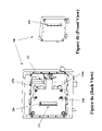
- FIG. 4 a is a first view of a shutter mechanism according to an embodiment of the present invention.
- FIG. 4 b is a second view of a shutter mechanism according to an embodiment of the present invention.
- FIG. 4 c is a third view of a shutter mechanism according to an embodiment of the present invention.
- a preferred embodiment of the present invention provides a non-stop drive-through scanning system 10 for imaging the contents of moving target vehicles, e.g., 15 a , 15 b , 15 c , etc. (referred to herein individually as 15 ).
- the preferred embodiments of the present invention facilitate back-to-back scanning of moving vehicles 15 a , 15 b , 15 c , etc., without the need to stop the vehicle and initiate scanning manually, thus facilitating increased rate of the flow of commerce.
- the system of FIGS. 1 a and 1 b allows the driver of a vehicle, e.g., van, truck, train, etc. to enter the scanning zone 20 without the need to stop or exit from the target vehicle 15 .
- the scanning zone 20 is defined by the space between opposing source and detector towers 25 , 30 . Details regarding various embodiments of the source and detector towers are described in the patents and applications listed above which are incorporated herein by reference.
- the source tower 25 may include a radiation source such as a 3.7 ⁇ 10 10 Bq shuttered source of Cs-137 gamma-rays, i.e., 662 keV gamma-ray energy.
- a Co-60 source may be used.
- a suitable source is readily available as Model Nos. SH-F-2 and SH-F-3 from Ohmart Corporation of Ohio.
- the radiation source may include a collimator that provides desired vertical and lateral opening specifications.
- the radiation source provides gamma-rays that are only moderately attenuated by steel walls typically found in tanker trucks or railroad cars. Yet such rays are sufficiently attenuated by contraband packages to make them easily detectable by measuring the penetration of the gamma-rays emitted from the source and deriving relative material densities therefrom. In addition, there is negligible scattering of the gamma-ray energy from the tanker walls or cargo, much less than would occur if a high-powered x-ray source was utilized.
- An exemplary detector tower 30 includes a detector array that employs a plurality of high efficiency gamma-ray detectors, e.g., between twenty and sixty, e.g., forty-eight, detectors arranged in a vertical column.
- the detectors make it possible to scan the target vehicle with a very low intensity gamma-ray field.
- high efficiency detectors are used, such as are available as Part No. 1.5M1.5M1.5, NaI (Tl) (sodium iodide crystal, thallium activated) (with R2060 photomultiplier tube) from BICRON of Ohio.
- Such gamma-ray detectors are scintillation counter-type detectors and are 3.8 cm in diameter, 3.8 cm high and mounted on a 3.8 cm photo-multiplier tube (PMT).
- the detector array includes a plurality of staggered NaI/PMT square photon detector elements 100 .
- Each individual detector is 1.125′′ (2.858 cm) square and has a pitch P smaller than the diameter (d) of the staggered detector elements 100 .
- Two (2) vertical rows R of staggered detector elements 100 are employed, instead of a single row of detectors. The two (2) vertical rows R are vertically staggered from each other.
- the staggered detectors are staggered from each other in a vertical direction, yet their surfaces of each vertical row all lie in a same plane, thereby avoiding shadowing from any other staggered detector while enabling a smaller pitch P.
- At least one start/stop sensor 35 is located prior to the scanning zone and is used to determine when the cab or driver/passenger area 40 (hereafter “cab”) has cleared the scanning zone and the payload 45 of the target vehicle 15 is entering the scanning zone. Once the start/stop sensor 35 senses the payload 45 has entered, or is about to enter, the scanning zone, the non-stop system initiates an automatic scan.
- the start/stop sensor 35 may include at least one of optical, electrical, pressure, video technology or the like for determining the start/stop points and automatic scan initiations as described above. More particularly, and by way of example, sensor technologies may be employed to count axles and/or measure the space between the cab 40 and the payload 45 .
- the at least one start/stop sensor 35 is located prior to the scanning zone and is above the level of the driving surface.
- the start/stop sensor 35 is located within or very near to the driving surface.
- the sensor may be outside of the driving lane or actually in the driving lane such that the target vehicle is driven directly over the start/stop sensor 35 .
- One skilled in the art can appreciate the various sensor configurations that would be considered to be within the scope of the present invention.
- the automatic initiation of a scan includes, among other features, controlling a shutter assembly, including a fast shutter mechanism 200 located in the source tower that allows at least a first fast shutter to open and allow radiation from the radiation source to exit through beam aperture 210 in a sufficient time, e.g., on the order of a few tens of milliseconds, between detection of the cab and the payload by the start/stop sensor, so as to allow for a complete payload scan, i.e., including the beginning edge of the payload, while the target vehicle is moving, i.e., at speeds of up to 10 miles per hour, with normal operating range of between 5–10 mph.
- a shutter assembly including a fast shutter mechanism 200 located in the source tower that allows at least a first fast shutter to open and allow radiation from the radiation source to exit through beam aperture 210 in a sufficient time, e.g., on the order of a few tens of milliseconds, between detection of the cab and the payload by the start/stop sensor, so as
- the system and method of the present invention facilitates a fast shutter opening time on the order of 50 milliseconds or less, preferably 40 milliseconds, to allow the shutter to fully open after the cab passes the start/stop sensor when a target vehicle driving at 7 MPH proceeds through the non-stop system.
- the fast shutter mechanism is controlled so as to close the at least one shutter at the end of the payload, before a second target vehicle enters the scanning zone.
- the time for the fast shutter to close is, for example, on the order of no less than 100 milliseconds, preferably on the order of 350 milliseconds.
- the latter closing time reflects a desired traffic pattern of vehicles allowing for at least 15 feet of separation between the payload trailing edge and the leading edge of the next target vehicle.
- the fast shutter mechanism utilizes at least one linear sliding shielding block 220 driven by an electromagnetic pulse actuated by a solenoid assembly 230 .
- the shutter shielding block 220 operates to attenuate the radiation source. i.e., gamma source, to within acceptable exposure levels.
- the configuration of the shutter shielding block 220 provides shielding of off-axis radiation exiting from the source assembly.
- the shutter shielding block comprises tungsten, with a thickness of approximately 2.4 inches (6.1 cm).
- An exemplary solenoid assembly 230 includes two electromechanical solenoids 235 a and 235 b operating together and control by solenoid drive electronics 237 to pull the shutter to the open position.
- the solenoids 235 a and 235 b are sized to open the shutter and allow radiation from the radiation source to exit through beam aperture 210 independently in the case of the failure of the other. This design, though resulting in a slightly slower shutter opening time, avoids system shut down altogether. And as described further below, shutter diagnostics will report the solenoid failure, i.e., the slower than normal opening time to the shutter mechanism control system and alert operators to the need for repair.
- a return spring 240 is used to close the fast shutter 210 in response to the start/stop sensor sensing the end of the payload.
- the return spring 240 is sized to provide enough energy to close the shutter in less than approximately 350 milliseconds, yet not provide excess force required to open the shutter 210 .
- the non-stop system may include at least one radiation sensor 50 , such as at least one rate meter, for sensing the levels of radiation, i.e., gamma or x-ray, outside of the confines of the scanning zone 20 as a protective measure.
- An alarm or other indication mechanism is triggered by at least one radiation sensor 50 to alert drivers, passengers, and other 3 rd parties to the potential for radiation exposure in the area around each scanning zone 20 .
- the shutter assembly described herein with respect to the preferred embodiments of the present invention also includes a failsafe operating design, wherein the at least one shutter fails in a closed condition, thus ensuring safety from possible radiation exposure in the event of, for example, a system power failure, a system error, or shutter failure.
- the control system for the shutter assembly includes safety interlocks. For example, a key switch is used to control access to the shutter controls. The primary shutter must be opened by an operator through a pushbutton and the secondary, i.e., fast, shutter, must be enabled through a pushbutton. The portal system must be functional and enabled for operation. Emergency stops de-energize both the primary and secondary shutters directly in the event of an operator initiated emergency stop condition.
- the control system indicates shutter status to an operator through open/close status sensors.
- shutter diagnostics are incorporated into the control system and shutter assembly to report shutter failure status by providing error signals for the following failure conditions: shutter opening time exceeds preset value; shutter closing time exceeds preset value; shutter in transit, i.e., not in closed or open position; shutter current exceeds preset value; and shutter temperature exceeds preset temperature. The latter is measured as the output of a solenoid field effect transistor switch temperature sensor.
- At least part of the source radiation from the radiation tower is detected by the detector array within the detector tower for imaging the contents of the target vehicle through a process of discrete photon counting.
- This process is described in detail in each of the patents and applications that have been incorporated herein by reference.
- showing the detectors from the detector array are coupled through, for example, 16-channel processing units, RS-485 line drivers, and an RS-485 interface card to a computer, wherein the computer processes discrete photon count information received from the detectors and causes a display device to display an image of the contents of a target vehicle, in response thereto.
- the detectors are coupled in groups of 16 to 16-channel data processing circuits. Preferably, twenty (20) groups of detectors are used.
- the number of detectors used is variable depending on the height of the vehicles to be inspected and the resolution, i.e., number of pixels, in the image desired. In a preferred embodiment, 320 detectors are used.
- the data processing circuits of which there are preferably twenty (2), are each coupled to an RS-485 line driver, which is coupled to an RS-485 interface.
- the RS-485 interface is embodied on a circuit card located within a computer system.
- a suitable RS-485 interface is available as Model No. 516-485, Part No. 3054 from Seal Level Systems, Inc., and from numerous other vendors under respective model/part number designations.
- Each of the radiation detectors is coupled to a preamplifier within the 16-channel data processing circuits.
- Each preamplifier is coupled to an amplifier, which is in turn coupled to a discriminator.
- Each discriminator is coupled to a pulse generator, which generates an electrical pulse for each photon received into the radiation detector coupled thereto.
- the pulse generators within each of the 16-channel data processing circuits is coupled to a line driver.
- Each of the 16-channel data processing circuits includes its own line driver.
- the line drivers operate under the programmatic control of a firmware operating system.
- the preamplifiers, and amplifiers function in a conventional manner to amplify signals generated by the detectors. Outputs of the amplifiers are passed along to the discriminators, which impose a noise threshold on the amplified signal.
- Waveforms within the amplified signal that exceed the noise threshold are passed along to the pulse generator, which generates a pulse for each waveform within the amplified signal corresponding to a received gamma-ray or x-ray photon.
- the line driver passes the pulses generated by each of the pulse generators within a particular 16-channel data processing circuit along to the computer system via the RS-485 interface.
- the computer system operates programmatically under the control of a software system.
- the computer system receives detector pulses from each of the 16-channel data processors, in response to the detection of individual photons by the detectors.
- the software system processes the incoming detector pulses, evaluating their relative amplitudes, i.e., energies, and generates a radio graphic image-like display output signal in response thereto.
- the radio graphic, image-like display output signal is coupled to the graphical display device and is used by the graphical display device to generate a graphical representation of the densities within the vehicle under inspection.
- the system described herein is utilized to generate a graphical representation, i.e., a “picture”, of the densities of the contents of the target vehicle.
- a graphical representation i.e., a “picture”
- this allows for easy visual interpretation of the results of the scanning of the target vehicle under inspection, as opposed to interpreting more subtle indications of the densities within the vehicle under inspection as may be required in prior art systems.
- the preferred imaging software system causes the display of a reference image simultaneous with the image generated in response to the target vehicle under inspection, so that an operator of the present embodiment can easily make a visual comparison between what a vehicle of the same type or having the same type of cargo being inspected should “look like”, and what the vehicle and cargo under inspection actually “looks like”.
- Such side-by-side inspection further simplifies the detection of contraband using the present embodiment.
Abstract
Description
Claims (21)
Priority Applications (7)
| Application Number | Priority Date | Filing Date | Title |
|---|---|---|---|
| US10/767,723 US7039159B2 (en) | 2004-01-30 | 2004-01-30 | Method and system for automatically scanning and imaging the contents of a moving target |
| MXPA06008579A MXPA06008579A (en) | 2004-01-30 | 2004-09-27 | Method ans system for automatically scanning and imaging the contents of a moving target. |
| EP04821675A EP1709433A4 (en) | 2004-01-30 | 2004-09-27 | Method ans system for automatically scanning and imaging the contents of a moving target |
| CNA2004800407281A CN1906479A (en) | 2004-01-30 | 2004-09-27 | Method and system for automatically scanning and imaging the contents of a moving target |
| PCT/US2004/031725 WO2005098401A2 (en) | 2004-01-30 | 2004-09-27 | Method ans system for automatically scanning and imaging the contents of a moving target |
| US11/370,883 US7215738B2 (en) | 2004-01-30 | 2006-03-09 | Method and system for automatically scanning and imaging the contents of a moving target |
| US11/730,503 US7352844B1 (en) | 2004-01-30 | 2007-04-02 | Method and system for automatically scanning and imaging the contents of a moving target |
Applications Claiming Priority (1)
| Application Number | Priority Date | Filing Date | Title |
|---|---|---|---|
| US10/767,723 US7039159B2 (en) | 2004-01-30 | 2004-01-30 | Method and system for automatically scanning and imaging the contents of a moving target |
Related Child Applications (1)
| Application Number | Title | Priority Date | Filing Date |
|---|---|---|---|
| US11/370,883 Continuation US7215738B2 (en) | 2004-01-30 | 2006-03-09 | Method and system for automatically scanning and imaging the contents of a moving target |
Publications (2)
| Publication Number | Publication Date |
|---|---|
| US20050169421A1 US20050169421A1 (en) | 2005-08-04 |
| US7039159B2 true US7039159B2 (en) | 2006-05-02 |
Family
ID=34807726
Family Applications (2)
| Application Number | Title | Priority Date | Filing Date |
|---|---|---|---|
| US10/767,723 Active 2024-06-25 US7039159B2 (en) | 2004-01-30 | 2004-01-30 | Method and system for automatically scanning and imaging the contents of a moving target |
| US11/370,883 Expired - Fee Related US7215738B2 (en) | 2004-01-30 | 2006-03-09 | Method and system for automatically scanning and imaging the contents of a moving target |
Family Applications After (1)
| Application Number | Title | Priority Date | Filing Date |
|---|---|---|---|
| US11/370,883 Expired - Fee Related US7215738B2 (en) | 2004-01-30 | 2006-03-09 | Method and system for automatically scanning and imaging the contents of a moving target |
Country Status (5)
| Country | Link |
|---|---|
| US (2) | US7039159B2 (en) |
| EP (1) | EP1709433A4 (en) |
| CN (1) | CN1906479A (en) |
| MX (1) | MXPA06008579A (en) |
| WO (1) | WO2005098401A2 (en) |
Cited By (61)
| Publication number | Priority date | Publication date | Assignee | Title |
|---|---|---|---|---|
| US20040134986A1 (en) * | 2001-05-08 | 2004-07-15 | Wolfgang Studer | X-ray system comprising an x-ray source, a detector assembly, and an aperture |
| US20060140341A1 (en) * | 2003-06-20 | 2006-06-29 | James Carver | Relocatable x-ray imaging system and method for inspecting commercial vehicles and cargo containers |
| US20070071165A1 (en) * | 2004-01-30 | 2007-03-29 | Science Applications International Corporation | Method and system for automatically scanning and imaging the contents of a moving target |
| US7352844B1 (en) | 2004-01-30 | 2008-04-01 | Science Applications International Corporation | Method and system for automatically scanning and imaging the contents of a moving target |
| US20080089476A1 (en) * | 2006-10-13 | 2008-04-17 | Zhiqiang Chen | Apparatus and method for quick imaging and inspecting moving target |
| WO2008046260A1 (en) | 2006-10-13 | 2008-04-24 | Nuctech Company Limited | A system and dodging method for imaging and detecting a moving object |
| US20080253514A1 (en) * | 2005-02-25 | 2008-10-16 | Rapiscan Systems Limited | X-Ray Security Inspection Machine |
| JP2009503558A (en) * | 2006-10-13 | 2009-01-29 | ヌクテック カンパニー リミテッド | Control unit used for radiation source and control method thereof, and radiation inspection system and method thereof |
| US20090274270A1 (en) * | 2002-07-23 | 2009-11-05 | Andreas Kotowski | Single Boom Cargo Scanning System |
| JP2010511153A (en) * | 2006-11-28 | 2010-04-08 | イノベイティブ アメリカン テクノロジー, インコーポレイテッド | Multi-stage system for verifying container contents |
| US20100085066A1 (en) * | 2003-09-15 | 2010-04-08 | Peschmann Kristian R | Methods and systems for the rapid detection of concealed objects |
| US20100189226A1 (en) * | 2002-07-23 | 2010-07-29 | Andreas Kotowski | Rotatable boom cargo scanning system |
| CN101162209B (en) * | 2006-10-13 | 2010-08-25 | 清华大学 | Equipment and method for quick-speed image-forming checking mobile target |
| US20110004002A1 (en) * | 2008-02-29 | 2011-01-06 | Basf Se | Process for preparing alkyl 2-alkoxymethylene-4,4-difluoro-3-oxobutyrates |
| US20110038453A1 (en) * | 2002-07-23 | 2011-02-17 | Edward James Morton | Compact Mobile Cargo Scanning System |
| US20110064192A1 (en) * | 2002-07-23 | 2011-03-17 | Edward James Morton | Four Sided Imaging System and Method for Detection of Contraband |
| US20110098870A1 (en) * | 2008-02-28 | 2011-04-28 | Edward James Morton | Mobile Scanning Systems |
| US20110116597A1 (en) * | 2002-07-23 | 2011-05-19 | Neeraj Agrawal | Cargo Scanning System |
| US20110116599A1 (en) * | 2008-02-28 | 2011-05-19 | Rapiscan Security Products, Inc. | Scanning Systems |
| US20110116600A1 (en) * | 2008-02-28 | 2011-05-19 | Edward James Morton | Scanning Systems |
| US20110135056A1 (en) * | 2008-05-20 | 2011-06-09 | Edward James Morton | Scanner Systems |
| US20110142203A1 (en) * | 2008-05-20 | 2011-06-16 | Edward James Morton | Gantry Scanner Systems |
| US20110204243A1 (en) * | 2008-06-11 | 2011-08-25 | Joseph Bendahan | Composite Gamma-Neutron Detection System |
| US8213570B2 (en) | 2006-02-27 | 2012-07-03 | Rapiscan Systems, Inc. | X-ray security inspection machine |
| US8314394B1 (en) | 2009-11-04 | 2012-11-20 | Science Applications International Corporation | System and method for three-dimensional imaging using scattering from annihilation coincidence photons |
| US8831176B2 (en) | 2008-05-20 | 2014-09-09 | Rapiscan Systems, Inc. | High energy X-ray inspection system using a fan-shaped beam and collimated backscatter detectors |
| US8837670B2 (en) | 2006-05-05 | 2014-09-16 | Rapiscan Systems, Inc. | Cargo inspection system |
| US8837669B2 (en) | 2003-04-25 | 2014-09-16 | Rapiscan Systems, Inc. | X-ray scanning system |
| US8859981B1 (en) | 2012-11-08 | 2014-10-14 | Leidos, Inc. | Method for autonomous self-blanking by radiation portal monitors to minimize the interference from pulsed X-rays radiation |
| US20140314201A1 (en) * | 2011-12-30 | 2014-10-23 | Tsinghua University | Methods and apparatuses for measuring effective atomic number of an object |
| US8885794B2 (en) | 2003-04-25 | 2014-11-11 | Rapiscan Systems, Inc. | X-ray tomographic inspection system for the identification of specific target items |
| US8963094B2 (en) | 2008-06-11 | 2015-02-24 | Rapiscan Systems, Inc. | Composite gamma-neutron detection system |
| US8971485B2 (en) | 2008-02-28 | 2015-03-03 | Rapiscan Systems, Inc. | Drive-through scanning systems |
| US9020095B2 (en) | 2003-04-25 | 2015-04-28 | Rapiscan Systems, Inc. | X-ray scanners |
| US9036779B2 (en) | 2008-02-28 | 2015-05-19 | Rapiscan Systems, Inc. | Dual mode X-ray vehicle scanning system |
| US9048061B2 (en) | 2005-12-16 | 2015-06-02 | Rapiscan Systems, Inc. | X-ray scanners and X-ray sources therefor |
| US9057679B2 (en) | 2012-02-03 | 2015-06-16 | Rapiscan Systems, Inc. | Combined scatter and transmission multi-view imaging system |
| US20150219786A1 (en) * | 2012-08-24 | 2015-08-06 | Terex Mhps Gmbh | System for the contactless inspection of containers, particularly iso containers, within a loading and unloading plant |
| US9113839B2 (en) | 2003-04-25 | 2015-08-25 | Rapiscon Systems, Inc. | X-ray inspection system and method |
| US9218933B2 (en) | 2011-06-09 | 2015-12-22 | Rapidscan Systems, Inc. | Low-dose radiographic imaging system |
| US9223050B2 (en) | 2005-04-15 | 2015-12-29 | Rapiscan Systems, Inc. | X-ray imaging system having improved mobility |
| US9310323B2 (en) | 2009-05-16 | 2016-04-12 | Rapiscan Systems, Inc. | Systems and methods for high-Z threat alarm resolution |
| US20170010383A1 (en) * | 2014-01-23 | 2017-01-12 | Sc Mb Telecom Ltd. Srl | System and method for nonintrusive complete aircraft inspection |
| US9557427B2 (en) | 2014-01-08 | 2017-01-31 | Rapiscan Systems, Inc. | Thin gap chamber neutron detectors |
| US9632205B2 (en) | 2011-02-08 | 2017-04-25 | Rapiscan Systems, Inc. | Covert surveillance using multi-modality sensing |
| US9787151B2 (en) | 2012-03-08 | 2017-10-10 | Leidos, Inc. | Radial flux alternator |
| US9791590B2 (en) | 2013-01-31 | 2017-10-17 | Rapiscan Systems, Inc. | Portable security inspection system |
| US9823383B2 (en) | 2013-01-07 | 2017-11-21 | Rapiscan Systems, Inc. | X-ray scanner with partial energy discriminating detector array |
| US9958569B2 (en) | 2002-07-23 | 2018-05-01 | Rapiscan Systems, Inc. | Mobile imaging system and method for detection of contraband |
| US10295483B2 (en) | 2005-12-16 | 2019-05-21 | Rapiscan Systems, Inc. | Data collection, processing and storage systems for X-ray tomographic images |
| US10345479B2 (en) | 2015-09-16 | 2019-07-09 | Rapiscan Systems, Inc. | Portable X-ray scanner |
| RU2716039C1 (en) * | 2018-12-27 | 2020-03-05 | Общество с ограниченной ответственностью "ИСБ.А" (ООО "ИСБ.А") | System for inspecting self-propelled vehicles, including cargoes, passengers and driver in vehicles, method for automatic radioscopic monitoring of moving objects and radiation scanning zone and method of forming shadow image of inspected object |
| US10591424B2 (en) | 2003-04-25 | 2020-03-17 | Rapiscan Systems, Inc. | X-ray tomographic inspection systems for the identification of specific target items |
| US10754056B2 (en) * | 2014-12-17 | 2020-08-25 | Tsinghua University | Quick vehicle check system and method adopting multi-dose regional scanning |
| US11175245B1 (en) | 2020-06-15 | 2021-11-16 | American Science And Engineering, Inc. | Scatter X-ray imaging with adaptive scanning beam intensity |
| US20220099601A1 (en) * | 2019-01-04 | 2022-03-31 | Nuctech (Beijing) Company Limited | Radiation inspection apparatus and radiation inspection method |
| US11300703B2 (en) | 2015-03-20 | 2022-04-12 | Rapiscan Systems, Inc. | Hand-held portable backscatter inspection system |
| US11340361B1 (en) | 2020-11-23 | 2022-05-24 | American Science And Engineering, Inc. | Wireless transmission detector panel for an X-ray scanner |
| US11525930B2 (en) | 2018-06-20 | 2022-12-13 | American Science And Engineering, Inc. | Wavelength-shifting sheet-coupled scintillation detectors |
| US11579327B2 (en) | 2012-02-14 | 2023-02-14 | American Science And Engineering, Inc. | Handheld backscatter imaging systems with primary and secondary detector arrays |
| US11796489B2 (en) | 2021-02-23 | 2023-10-24 | Rapiscan Systems, Inc. | Systems and methods for eliminating cross-talk signals in one or more scanning systems having multiple X-ray sources |
Families Citing this family (29)
| Publication number | Priority date | Publication date | Assignee | Title |
|---|---|---|---|---|
| US7142109B1 (en) * | 2001-10-26 | 2006-11-28 | Innovative American Technology, Inc. | Container verification system for non-invasive detection of contents |
| GB0309379D0 (en) | 2003-04-25 | 2003-06-04 | Cxr Ltd | X-ray scanning |
| GB0309385D0 (en) * | 2003-04-25 | 2003-06-04 | Cxr Ltd | X-ray monitoring |
| US8804899B2 (en) | 2003-04-25 | 2014-08-12 | Rapiscan Systems, Inc. | Imaging, data acquisition, data transmission, and data distribution methods and systems for high data rate tomographic X-ray scanners |
| TW200729923A (en) * | 2006-01-26 | 2007-08-01 | Avision Inc | Method for identifying leading edge or image range of scanned image |
| JP4918511B2 (en) * | 2008-02-25 | 2012-04-18 | 三菱重工業株式会社 | Vehicle inspection device |
| GB0803644D0 (en) | 2008-02-28 | 2008-04-02 | Rapiscan Security Products Inc | Scanning systems |
| US8586955B2 (en) * | 2010-09-22 | 2013-11-19 | Ko Khee Tay | Apparatus and method for attenuating high energy radiation based on detected vehicle type |
| WO2012049571A2 (en) * | 2010-10-14 | 2012-04-19 | Smiths Heimann Gmbh | Systems and methods for scanning an object while avoiding radiation exposure |
| GB2502732B (en) * | 2011-01-31 | 2017-02-22 | Rapiscan Systems Inc | Dual mode X-ray vehicle scanning system |
| KR102067367B1 (en) | 2011-09-07 | 2020-02-11 | 라피스캔 시스템스, 인코포레이티드 | X-ray inspection method that integrates manifest data with imaging/detection processing |
| JP5047389B2 (en) * | 2011-10-28 | 2012-10-10 | 三菱重工業株式会社 | Vehicle inspection device |
| US9274065B2 (en) * | 2012-02-08 | 2016-03-01 | Rapiscan Systems, Inc. | High-speed security inspection system |
| RO127852B1 (en) * | 2012-05-21 | 2019-03-29 | Mb Telecom Ltd Srl | Method and system for non-intrusive inspection of cargo type objects: motor vehicles, containers, train cars |
| CN103529061B (en) | 2012-07-04 | 2016-03-09 | 同方威视技术股份有限公司 | Vehicle mounted type radiation checking system |
| EP3025147A4 (en) | 2013-07-23 | 2017-03-22 | Rapiscan Systems, Inc. | Methods for improving processing speed for object inspection |
| CN104950338B (en) * | 2014-03-24 | 2020-11-24 | 北京君和信达科技有限公司 | System and method for radiation inspection of moving objects |
| CN105022095B (en) * | 2014-04-24 | 2021-10-29 | 北京君和信达科技有限公司 | Quick-pass type mobile target radiation inspection method and system |
| WO2016003547A1 (en) | 2014-06-30 | 2016-01-07 | American Science And Engineering, Inc. | Rapidly relocatable modular cargo container scanner |
| CN105438756B (en) * | 2014-08-22 | 2019-03-29 | 清华大学 | A kind of small vehicle inspection system |
| CN104374785B (en) * | 2014-11-14 | 2017-12-05 | 北京君和信达科技有限公司 | A kind of continuous radiation scanning system and method |
| CN105333826B (en) * | 2015-12-04 | 2019-02-22 | 同方威视技术股份有限公司 | The quick inspection method of vehicle and system |
| EP3420563A4 (en) | 2016-02-22 | 2020-03-11 | Rapiscan Systems, Inc. | Systems and methods for detecting threats and contraband in cargo |
| CN108897055B (en) * | 2016-02-24 | 2020-02-21 | 北京君和信达科技有限公司 | Radiation source control method and quick-pass type security inspection system |
| CN110199373B (en) | 2017-01-31 | 2021-09-28 | 拉皮斯坎系统股份有限公司 | High power X-ray source and method of operation |
| CN107228868A (en) * | 2017-06-29 | 2017-10-03 | 北京君和信达科技有限公司 | Radiation checking system and radiation testing method |
| US11212902B2 (en) | 2020-02-25 | 2021-12-28 | Rapiscan Systems, Inc. | Multiplexed drive systems and methods for a multi-emitter X-ray source |
| US11193898B1 (en) | 2020-06-01 | 2021-12-07 | American Science And Engineering, Inc. | Systems and methods for controlling image contrast in an X-ray system |
| GB2616274A (en) * | 2022-03-01 | 2023-09-06 | Illinois Tool Works | X-ray inspection apparatus and method |
Citations (5)
| Publication number | Priority date | Publication date | Assignee | Title |
|---|---|---|---|---|
| US6031890A (en) * | 1993-04-05 | 2000-02-29 | Heimann Systems Gmbh & Co. Kg | Monitoring installation for containers and trucks |
| US6255654B1 (en) * | 1995-10-23 | 2001-07-03 | Science Applications International Corporation | Density detection using discrete photon counting |
| US6400795B2 (en) * | 2000-07-27 | 2002-06-04 | Seiko Instruments Inc. | X-ray fluorescence analyzer |
| US6507025B1 (en) | 1995-10-23 | 2003-01-14 | Science Applications International Corporation | Density detection using real time discrete photon counting for fast moving targets |
| US6649906B2 (en) * | 2000-09-29 | 2003-11-18 | Schlumberger Technology Corporation | Method and apparatus for safely operating radiation generators in while-drilling and while-tripping applications |
Family Cites Families (12)
| Publication number | Priority date | Publication date | Assignee | Title |
|---|---|---|---|---|
| US3390269A (en) * | 1964-06-18 | 1968-06-25 | Packard Instrument Co Inc | Apparatus for automatic standardization with external standards in liquid scintillation spectrometry |
| DE1764217C3 (en) * | 1967-04-27 | 1974-01-17 | Industrial Nucleonics Corp., Columbus, Ohio (V.St.A.) | Safety lock for the housing of a radioactive radiation source |
| US3829695A (en) * | 1971-08-26 | 1974-08-13 | Molins Ltd | Rod guide assembly for continuous rod making machines |
| US4817123A (en) * | 1984-09-21 | 1989-03-28 | Picker International | Digital radiography detector resolution improvement |
| US4963746A (en) * | 1986-11-25 | 1990-10-16 | Picker International, Inc. | Split energy level radiation detection |
| US4924098A (en) * | 1987-11-30 | 1990-05-08 | Radiation Detectors, Inc. | Nuclear radiation level detector |
| US4946256A (en) * | 1989-01-11 | 1990-08-07 | Nm Laser Products, Inc. | Right angle shutter for laser beam |
| US5834780A (en) * | 1996-05-29 | 1998-11-10 | Picker International, Inc. | Scanning line source for gamma camera |
| US5986275A (en) * | 1996-06-07 | 1999-11-16 | The University Of Virginia Patent Foundation | Reusable shielded marker for nuclear medicine imaging |
| US7045788B2 (en) * | 2003-08-04 | 2006-05-16 | Thermo Electron Corporation | Multi-way radiation monitoring |
| US7046768B1 (en) * | 2003-11-10 | 2006-05-16 | Inspx Llc | Shutter-shield for x-ray protection |
| US7039159B2 (en) * | 2004-01-30 | 2006-05-02 | Science Applications International Corporation | Method and system for automatically scanning and imaging the contents of a moving target |
-
2004
- 2004-01-30 US US10/767,723 patent/US7039159B2/en active Active
- 2004-09-27 MX MXPA06008579A patent/MXPA06008579A/en unknown
- 2004-09-27 CN CNA2004800407281A patent/CN1906479A/en active Pending
- 2004-09-27 WO PCT/US2004/031725 patent/WO2005098401A2/en not_active Application Discontinuation
- 2004-09-27 EP EP04821675A patent/EP1709433A4/en not_active Withdrawn
-
2006
- 2006-03-09 US US11/370,883 patent/US7215738B2/en not_active Expired - Fee Related
Patent Citations (6)
| Publication number | Priority date | Publication date | Assignee | Title |
|---|---|---|---|---|
| US6031890A (en) * | 1993-04-05 | 2000-02-29 | Heimann Systems Gmbh & Co. Kg | Monitoring installation for containers and trucks |
| US6255654B1 (en) * | 1995-10-23 | 2001-07-03 | Science Applications International Corporation | Density detection using discrete photon counting |
| US6507025B1 (en) | 1995-10-23 | 2003-01-14 | Science Applications International Corporation | Density detection using real time discrete photon counting for fast moving targets |
| US6552346B2 (en) | 1995-10-23 | 2003-04-22 | Science Applications International Corporation | Density detection using discrete photon counting |
| US6400795B2 (en) * | 2000-07-27 | 2002-06-04 | Seiko Instruments Inc. | X-ray fluorescence analyzer |
| US6649906B2 (en) * | 2000-09-29 | 2003-11-18 | Schlumberger Technology Corporation | Method and apparatus for safely operating radiation generators in while-drilling and while-tripping applications |
Non-Patent Citations (1)
| Title |
|---|
| International Search Report and Written Opinion for Application No. PCT/US04/31725, dated Sep. 30, 2005 (mailing date). |
Cited By (153)
| Publication number | Priority date | Publication date | Assignee | Title |
|---|---|---|---|---|
| US7308076B2 (en) | 2001-05-08 | 2007-12-11 | Smiths Heimann Gmbh | X-ray system comprising an X-ray source, a detector assembly, and a shutter |
| US20040134986A1 (en) * | 2001-05-08 | 2004-07-15 | Wolfgang Studer | X-ray system comprising an x-ray source, a detector assembly, and an aperture |
| US8356937B2 (en) | 2002-07-23 | 2013-01-22 | Rapiscan Systems, Inc. | Rotatable boom cargo scanning system |
| US9025731B2 (en) | 2002-07-23 | 2015-05-05 | Rapiscan Systems, Inc. | Cargo scanning system |
| US9052403B2 (en) | 2002-07-23 | 2015-06-09 | Rapiscan Systems, Inc. | Compact mobile cargo scanning system |
| US9223049B2 (en) | 2002-07-23 | 2015-12-29 | Rapiscan Systems, Inc. | Cargo scanning system with boom structure |
| US20110116597A1 (en) * | 2002-07-23 | 2011-05-19 | Neeraj Agrawal | Cargo Scanning System |
| US11143783B2 (en) | 2002-07-23 | 2021-10-12 | Rapiscan Systems, Inc. | Four-sided imaging system and method for detection of contraband |
| US8275091B2 (en) | 2002-07-23 | 2012-09-25 | Rapiscan Systems, Inc. | Compact mobile cargo scanning system |
| US8687765B2 (en) | 2002-07-23 | 2014-04-01 | Rapiscan Systems, Inc. | Cargo scanning system with boom structure |
| US8491189B2 (en) | 2002-07-23 | 2013-07-23 | Rapiscan Systems, Inc. | Radiation source apparatus |
| US10976465B2 (en) | 2002-07-23 | 2021-04-13 | Rapiscan Systems, Inc. | Two-sided, multi-energy imaging system and method for the inspection of cargo |
| US8059781B2 (en) | 2002-07-23 | 2011-11-15 | Rapiscan Systems, Inc. | Cargo scanning system |
| US10670769B2 (en) | 2002-07-23 | 2020-06-02 | Rapiscan Systems, Inc. | Compact mobile cargo scanning system |
| US7963695B2 (en) | 2002-07-23 | 2011-06-21 | Rapiscan Systems, Inc. | Rotatable boom cargo scanning system |
| US8503605B2 (en) | 2002-07-23 | 2013-08-06 | Rapiscan Systems, Inc. | Four sided imaging system and method for detection of contraband |
| US20090274270A1 (en) * | 2002-07-23 | 2009-11-05 | Andreas Kotowski | Single Boom Cargo Scanning System |
| US8929509B2 (en) | 2002-07-23 | 2015-01-06 | Rapiscan Systems, Inc. | Four-sided imaging system and method for detection of contraband |
| US20110064192A1 (en) * | 2002-07-23 | 2011-03-17 | Edward James Morton | Four Sided Imaging System and Method for Detection of Contraband |
| US20110038453A1 (en) * | 2002-07-23 | 2011-02-17 | Edward James Morton | Compact Mobile Cargo Scanning System |
| US8668386B2 (en) | 2002-07-23 | 2014-03-11 | Rapiscan Systems, Inc. | Compact mobile cargo scanning system |
| US10007019B2 (en) | 2002-07-23 | 2018-06-26 | Rapiscan Systems, Inc. | Compact mobile cargo scanning system |
| US20100189226A1 (en) * | 2002-07-23 | 2010-07-29 | Andreas Kotowski | Rotatable boom cargo scanning system |
| US7876880B2 (en) | 2002-07-23 | 2011-01-25 | Rapiscan Systems, Inc. | Single boom cargo scanning system |
| US9958569B2 (en) | 2002-07-23 | 2018-05-01 | Rapiscan Systems, Inc. | Mobile imaging system and method for detection of contraband |
| US10901112B2 (en) | 2003-04-25 | 2021-01-26 | Rapiscan Systems, Inc. | X-ray scanning system with stationary x-ray sources |
| US10175381B2 (en) | 2003-04-25 | 2019-01-08 | Rapiscan Systems, Inc. | X-ray scanners having source points with less than a predefined variation in brightness |
| US10591424B2 (en) | 2003-04-25 | 2020-03-17 | Rapiscan Systems, Inc. | X-ray tomographic inspection systems for the identification of specific target items |
| US9618648B2 (en) | 2003-04-25 | 2017-04-11 | Rapiscan Systems, Inc. | X-ray scanners |
| US8837669B2 (en) | 2003-04-25 | 2014-09-16 | Rapiscan Systems, Inc. | X-ray scanning system |
| US8885794B2 (en) | 2003-04-25 | 2014-11-11 | Rapiscan Systems, Inc. | X-ray tomographic inspection system for the identification of specific target items |
| US11796711B2 (en) | 2003-04-25 | 2023-10-24 | Rapiscan Systems, Inc. | Modular CT scanning system |
| US9020095B2 (en) | 2003-04-25 | 2015-04-28 | Rapiscan Systems, Inc. | X-ray scanners |
| US9113839B2 (en) | 2003-04-25 | 2015-08-25 | Rapiscon Systems, Inc. | X-ray inspection system and method |
| US9675306B2 (en) | 2003-04-25 | 2017-06-13 | Rapiscan Systems, Inc. | X-ray scanning system |
| US9442082B2 (en) | 2003-04-25 | 2016-09-13 | Rapiscan Systems, Inc. | X-ray inspection system and method |
| US7769133B2 (en) | 2003-06-20 | 2010-08-03 | Rapiscan Systems, Inc. | Relocatable X-ray imaging system and method for inspecting commercial vehicles and cargo containers |
| US7991113B2 (en) | 2003-06-20 | 2011-08-02 | Rapiscan Security Products, Inc. | Relocatable x-ray imaging system and method for inspecting commercial vehicles and cargo containers |
| US9285498B2 (en) | 2003-06-20 | 2016-03-15 | Rapiscan Systems, Inc. | Relocatable X-ray imaging system and method for inspecting commercial vehicles and cargo containers |
| US7483510B2 (en) * | 2003-06-20 | 2009-01-27 | Rapiscan Security Products, Inc. | Relocatable X-ray imaging system and method for inspecting commercial vehicles and cargo containers |
| US20090161825A1 (en) * | 2003-06-20 | 2009-06-25 | James Carver | Relocatable X-Ray Imaging System and Method for Inspecting Commercial Vehicles and Cargo Containers |
| US20060140341A1 (en) * | 2003-06-20 | 2006-06-29 | James Carver | Relocatable x-ray imaging system and method for inspecting commercial vehicles and cargo containers |
| US20100085066A1 (en) * | 2003-09-15 | 2010-04-08 | Peschmann Kristian R | Methods and systems for the rapid detection of concealed objects |
| US9268058B2 (en) | 2003-09-15 | 2016-02-23 | Rapiscan Systems, Inc. | Methods and systems for the rapid detection of concealed objects |
| US8138770B2 (en) | 2003-09-15 | 2012-03-20 | Rapiscan Systems, Inc. | Methods and systems for the rapid detection of concealed objects |
| US8674706B2 (en) | 2003-09-15 | 2014-03-18 | Rapiscan Systems, Inc. | Methods and systems for the rapid detection of concealed objects |
| US20070071165A1 (en) * | 2004-01-30 | 2007-03-29 | Science Applications International Corporation | Method and system for automatically scanning and imaging the contents of a moving target |
| US7215738B2 (en) * | 2004-01-30 | 2007-05-08 | Science Applications International Corporation | Method and system for automatically scanning and imaging the contents of a moving target |
| US7352844B1 (en) | 2004-01-30 | 2008-04-01 | Science Applications International Corporation | Method and system for automatically scanning and imaging the contents of a moving target |
| US20080253514A1 (en) * | 2005-02-25 | 2008-10-16 | Rapiscan Systems Limited | X-Ray Security Inspection Machine |
| US7702069B2 (en) | 2005-02-25 | 2010-04-20 | Rapiscan Security Products, Inc. | X-ray security inspection machine |
| US9223050B2 (en) | 2005-04-15 | 2015-12-29 | Rapiscan Systems, Inc. | X-ray imaging system having improved mobility |
| US10295483B2 (en) | 2005-12-16 | 2019-05-21 | Rapiscan Systems, Inc. | Data collection, processing and storage systems for X-ray tomographic images |
| US9638646B2 (en) | 2005-12-16 | 2017-05-02 | Rapiscan Systems, Inc. | X-ray scanners and X-ray sources therefor |
| US9048061B2 (en) | 2005-12-16 | 2015-06-02 | Rapiscan Systems, Inc. | X-ray scanners and X-ray sources therefor |
| US10976271B2 (en) | 2005-12-16 | 2021-04-13 | Rapiscan Systems, Inc. | Stationary tomographic X-ray imaging systems for automatically sorting objects based on generated tomographic images |
| US9310322B2 (en) | 2006-02-27 | 2016-04-12 | Rapiscan Systems, Inc. | X-ray security inspection machine |
| US8213570B2 (en) | 2006-02-27 | 2012-07-03 | Rapiscan Systems, Inc. | X-ray security inspection machine |
| US9279901B2 (en) | 2006-05-05 | 2016-03-08 | Rapiscan Systems, Inc. | Cargo inspection system |
| US8837670B2 (en) | 2006-05-05 | 2014-09-16 | Rapiscan Systems, Inc. | Cargo inspection system |
| US7989770B2 (en) | 2006-10-13 | 2011-08-02 | Nuctech Company Limited | Control unit and control method for radiation source and radiation inspection system and method thereof |
| US20090065698A1 (en) * | 2006-10-13 | 2009-03-12 | Zhiqiang Chen | Control unit and control method for radiation source and radiation inspection system and method thereof |
| EP1970700A4 (en) * | 2006-10-13 | 2010-09-01 | Nuctech Co Ltd | A system and dodging method for imaging and detecting a moving object |
| CN101162209B (en) * | 2006-10-13 | 2010-08-25 | 清华大学 | Equipment and method for quick-speed image-forming checking mobile target |
| US20080089476A1 (en) * | 2006-10-13 | 2008-04-17 | Zhiqiang Chen | Apparatus and method for quick imaging and inspecting moving target |
| AU2006346222B2 (en) * | 2006-10-13 | 2010-07-15 | Nuctech Company Limited | System for image inspection of movable object and dodging method |
| WO2008046260A1 (en) | 2006-10-13 | 2008-04-24 | Nuctech Company Limited | A system and dodging method for imaging and detecting a moving object |
| AU2006346222A1 (en) * | 2006-10-13 | 2008-04-24 | Nuctech Company Limited | System for image inspection of movable object and dodging method |
| JP2009503558A (en) * | 2006-10-13 | 2009-01-29 | ヌクテック カンパニー リミテッド | Control unit used for radiation source and control method thereof, and radiation inspection system and method thereof |
| US7492861B2 (en) * | 2006-10-13 | 2009-02-17 | Tsinghua University | Apparatus and method for quick imaging and inspecting moving target |
| US7688945B2 (en) | 2006-10-13 | 2010-03-30 | Nuctech Company Limited | System for image inspection of movable object and dodging method |
| US20090225939A1 (en) * | 2006-10-13 | 2009-09-10 | Zhiqiang Chen | System for image inspection of movable object and dodging method |
| JP2010511153A (en) * | 2006-11-28 | 2010-04-08 | イノベイティブ アメリカン テクノロジー, インコーポレイテッド | Multi-stage system for verifying container contents |
| US9121958B2 (en) | 2008-02-28 | 2015-09-01 | Rapiscan Systems, Inc. | Scanning systems |
| US9429530B2 (en) | 2008-02-28 | 2016-08-30 | Rapiscan Systems, Inc. | Scanning systems |
| US10816691B2 (en) | 2008-02-28 | 2020-10-27 | Rapiscan Systems, Inc. | Multi-element detector systems |
| US10754058B2 (en) | 2008-02-28 | 2020-08-25 | Rapiscan Systems, Inc. | Drive-through scanning systems |
| US9036779B2 (en) | 2008-02-28 | 2015-05-19 | Rapiscan Systems, Inc. | Dual mode X-ray vehicle scanning system |
| US20110098870A1 (en) * | 2008-02-28 | 2011-04-28 | Edward James Morton | Mobile Scanning Systems |
| US8774357B2 (en) | 2008-02-28 | 2014-07-08 | Rapiscan Systems, Inc. | Scanning systems |
| US9158027B2 (en) | 2008-02-28 | 2015-10-13 | Rapiscan Systems, Inc. | Mobile scanning systems |
| US8644453B2 (en) | 2008-02-28 | 2014-02-04 | Rapiscan Systems, Inc. | Scanning systems |
| US8971485B2 (en) | 2008-02-28 | 2015-03-03 | Rapiscan Systems, Inc. | Drive-through scanning systems |
| US9817151B2 (en) | 2008-02-28 | 2017-11-14 | Rapiscan Systems, Inc. | Drive-through scanning systems |
| US11579328B2 (en) | 2008-02-28 | 2023-02-14 | Rapiscan Systems, Inc. | Drive-through scanning systems |
| US9835756B2 (en) | 2008-02-28 | 2017-12-05 | Rapiscan Systems, Inc. | Dual mode X-ray vehicle scanning system |
| US20110116599A1 (en) * | 2008-02-28 | 2011-05-19 | Rapiscan Security Products, Inc. | Scanning Systems |
| US8433036B2 (en) | 2008-02-28 | 2013-04-30 | Rapiscan Systems, Inc. | Scanning systems |
| US10007021B2 (en) | 2008-02-28 | 2018-06-26 | Rapiscan Systems, Inc. | Scanning systems |
| US20110116600A1 (en) * | 2008-02-28 | 2011-05-19 | Edward James Morton | Scanning Systems |
| US20110004002A1 (en) * | 2008-02-29 | 2011-01-06 | Basf Se | Process for preparing alkyl 2-alkoxymethylene-4,4-difluoro-3-oxobutyrates |
| US9332624B2 (en) | 2008-05-20 | 2016-05-03 | Rapiscan Systems, Inc. | Gantry scanner systems |
| US8840303B2 (en) | 2008-05-20 | 2014-09-23 | Rapiscan Systems, Inc. | Scanner systems |
| US20110135056A1 (en) * | 2008-05-20 | 2011-06-09 | Edward James Morton | Scanner Systems |
| US20110142203A1 (en) * | 2008-05-20 | 2011-06-16 | Edward James Morton | Gantry Scanner Systems |
| US8831176B2 (en) | 2008-05-20 | 2014-09-09 | Rapiscan Systems, Inc. | High energy X-ray inspection system using a fan-shaped beam and collimated backscatter detectors |
| US10098214B2 (en) | 2008-05-20 | 2018-10-09 | Rapiscan Systems, Inc. | Detector support structures for gantry scanner systems |
| US9688517B2 (en) | 2008-05-20 | 2017-06-27 | Rapiscan Systems, Inc. | Scanner systems |
| US8579506B2 (en) | 2008-05-20 | 2013-11-12 | Rapiscan Systems, Inc. | Gantry scanner systems |
| US20110204243A1 (en) * | 2008-06-11 | 2011-08-25 | Joseph Bendahan | Composite Gamma-Neutron Detection System |
| US8963094B2 (en) | 2008-06-11 | 2015-02-24 | Rapiscan Systems, Inc. | Composite gamma-neutron detection system |
| US8389941B2 (en) | 2008-06-11 | 2013-03-05 | Rapiscan Systems, Inc. | Composite gamma-neutron detection system |
| US8993970B2 (en) | 2008-06-11 | 2015-03-31 | Rapiscan Systems, Inc. | Photomultiplier and detection systems |
| US8389942B2 (en) | 2008-06-11 | 2013-03-05 | Rapiscan Systems, Inc. | Photomultiplier and detection systems |
| US8735833B2 (en) | 2008-06-11 | 2014-05-27 | Rapiscan Systems, Inc | Photomultiplier and detection systems |
| US9329285B2 (en) | 2008-06-11 | 2016-05-03 | Rapiscan Systems, Inc. | Composite gamma-neutron detection system |
| US9625606B2 (en) | 2009-05-16 | 2017-04-18 | Rapiscan Systems, Inc. | Systems and methods for high-Z threat alarm resolution |
| US9310323B2 (en) | 2009-05-16 | 2016-04-12 | Rapiscan Systems, Inc. | Systems and methods for high-Z threat alarm resolution |
| US8664609B2 (en) | 2009-11-04 | 2014-03-04 | Leidos, Inc. | System and method for three-dimensional imaging using scattering from annihilation coincidence photons |
| US8314394B1 (en) | 2009-11-04 | 2012-11-20 | Science Applications International Corporation | System and method for three-dimensional imaging using scattering from annihilation coincidence photons |
| US8426822B1 (en) | 2009-11-04 | 2013-04-23 | Science Application International Corporation | System and method for three-dimensional imaging using scattering from annihilation coincidence photons |
| US10408967B2 (en) | 2011-02-08 | 2019-09-10 | Rapiscan Systems, Inc. | Covert surveillance using multi-modality sensing |
| US10942291B2 (en) | 2011-02-08 | 2021-03-09 | Rapiscan Systems, Inc. | Covert surveillance using multi-modality sensing |
| US9632205B2 (en) | 2011-02-08 | 2017-04-25 | Rapiscan Systems, Inc. | Covert surveillance using multi-modality sensing |
| US11822041B2 (en) | 2011-02-08 | 2023-11-21 | Rapiscan Systems, Inc. | Systems and methods for improved atomic-number based material discrimination |
| US11307325B2 (en) | 2011-02-08 | 2022-04-19 | Rapiscan Systems, Inc. | Covert surveillance using multi-modality sensing |
| US9218933B2 (en) | 2011-06-09 | 2015-12-22 | Rapidscan Systems, Inc. | Low-dose radiographic imaging system |
| US20140314201A1 (en) * | 2011-12-30 | 2014-10-23 | Tsinghua University | Methods and apparatuses for measuring effective atomic number of an object |
| US9464997B2 (en) * | 2011-12-30 | 2016-10-11 | Nuctech Company Limited | Methods and apparatuses for measuring effective atomic number of an object |
| US10746674B2 (en) | 2012-02-03 | 2020-08-18 | Rapiscan Systems, Inc. | Combined scatter and transmission multi-view imaging system |
| US9057679B2 (en) | 2012-02-03 | 2015-06-16 | Rapiscan Systems, Inc. | Combined scatter and transmission multi-view imaging system |
| US9823201B2 (en) | 2012-02-03 | 2017-11-21 | Rapiscan Systems, Inc. | Combined scatter and transmission multi-view imaging system |
| US11371948B2 (en) | 2012-02-03 | 2022-06-28 | Rapiscan Systems, Inc. | Multi-view imaging system |
| US11579327B2 (en) | 2012-02-14 | 2023-02-14 | American Science And Engineering, Inc. | Handheld backscatter imaging systems with primary and secondary detector arrays |
| US9787151B2 (en) | 2012-03-08 | 2017-10-10 | Leidos, Inc. | Radial flux alternator |
| US20150219786A1 (en) * | 2012-08-24 | 2015-08-06 | Terex Mhps Gmbh | System for the contactless inspection of containers, particularly iso containers, within a loading and unloading plant |
| US9880315B2 (en) | 2012-11-08 | 2018-01-30 | Leidos, Inc. | Method for autonomous self-blanking by radiation portal monitors to minimize the interference from pulsed X-rays radiation |
| US9568637B2 (en) | 2012-11-08 | 2017-02-14 | Leidos, Inc. | Method for autonomous self-blanking by radiation portal monitors to minimize the interference from pulsed X-rays radiation |
| US8859981B1 (en) | 2012-11-08 | 2014-10-14 | Leidos, Inc. | Method for autonomous self-blanking by radiation portal monitors to minimize the interference from pulsed X-rays radiation |
| US9182515B2 (en) | 2012-11-08 | 2015-11-10 | Leidos, Inc. | Method for autonomous self-blanking by radiation portal monitors to minimize the interference from pulsed X-rays radiation |
| US10197700B2 (en) | 2012-11-08 | 2019-02-05 | Leidos, Inc. | Method for autonomous self-blanking by radiation portal monitors to minimize the interference from pulsed X-rays radiation |
| US10353109B2 (en) | 2013-01-07 | 2019-07-16 | Rapiscan Systems, Inc. | X-ray scanner with partial energy discriminating detector array |
| US10782440B2 (en) | 2013-01-07 | 2020-09-22 | Rapiscan Systems, Inc. | X-ray scanner with partial energy discriminating detector array |
| US9823383B2 (en) | 2013-01-07 | 2017-11-21 | Rapiscan Systems, Inc. | X-ray scanner with partial energy discriminating detector array |
| US10317566B2 (en) | 2013-01-31 | 2019-06-11 | Rapiscan Systems, Inc. | Portable security inspection system |
| US9791590B2 (en) | 2013-01-31 | 2017-10-17 | Rapiscan Systems, Inc. | Portable security inspection system |
| US11550077B2 (en) | 2013-01-31 | 2023-01-10 | Rapiscan Systems, Inc. | Portable vehicle inspection portal with accompanying workstation |
| US9557427B2 (en) | 2014-01-08 | 2017-01-31 | Rapiscan Systems, Inc. | Thin gap chamber neutron detectors |
| US11119244B2 (en) * | 2014-01-23 | 2021-09-14 | Sc Mb Telecom Ltd Srl | System and method for nonintrusive complete aircraft inspection |
| US20170010383A1 (en) * | 2014-01-23 | 2017-01-12 | Sc Mb Telecom Ltd. Srl | System and method for nonintrusive complete aircraft inspection |
| US10754056B2 (en) * | 2014-12-17 | 2020-08-25 | Tsinghua University | Quick vehicle check system and method adopting multi-dose regional scanning |
| US11300703B2 (en) | 2015-03-20 | 2022-04-12 | Rapiscan Systems, Inc. | Hand-held portable backscatter inspection system |
| US11561320B2 (en) | 2015-03-20 | 2023-01-24 | Rapiscan Systems, Inc. | Hand-held portable backscatter inspection system |
| US10345479B2 (en) | 2015-09-16 | 2019-07-09 | Rapiscan Systems, Inc. | Portable X-ray scanner |
| US11525930B2 (en) | 2018-06-20 | 2022-12-13 | American Science And Engineering, Inc. | Wavelength-shifting sheet-coupled scintillation detectors |
| WO2020139162A1 (en) * | 2018-12-27 | 2020-07-02 | Obshhestvo S Ogranichennoj Otvetstvennost`Yu "Isb.A" (Ooo "Isb.A") | System for screening vehicles and method of radioscopic control of moving objects |
| RU2716039C1 (en) * | 2018-12-27 | 2020-03-05 | Общество с ограниченной ответственностью "ИСБ.А" (ООО "ИСБ.А") | System for inspecting self-propelled vehicles, including cargoes, passengers and driver in vehicles, method for automatic radioscopic monitoring of moving objects and radiation scanning zone and method of forming shadow image of inspected object |
| US20220099601A1 (en) * | 2019-01-04 | 2022-03-31 | Nuctech (Beijing) Company Limited | Radiation inspection apparatus and radiation inspection method |
| US11822043B2 (en) * | 2019-01-04 | 2023-11-21 | Nuctech (Beijing) Company Limited | Radiation inspection apparatus comprising a radiation inspection device and wheels and radiation inspection method |
| US11175245B1 (en) | 2020-06-15 | 2021-11-16 | American Science And Engineering, Inc. | Scatter X-ray imaging with adaptive scanning beam intensity |
| US11340361B1 (en) | 2020-11-23 | 2022-05-24 | American Science And Engineering, Inc. | Wireless transmission detector panel for an X-ray scanner |
| US11726218B2 (en) | 2020-11-23 | 2023-08-15 | American Science arid Engineering, Inc. | Methods and systems for synchronizing backscatter signals and wireless transmission signals in x-ray scanning |
| US11796489B2 (en) | 2021-02-23 | 2023-10-24 | Rapiscan Systems, Inc. | Systems and methods for eliminating cross-talk signals in one or more scanning systems having multiple X-ray sources |
Also Published As
| Publication number | Publication date |
|---|---|
| US20050169421A1 (en) | 2005-08-04 |
| WO2005098401A3 (en) | 2005-11-10 |
| EP1709433A4 (en) | 2007-05-09 |
| WO2005098401A2 (en) | 2005-10-20 |
| CN1906479A (en) | 2007-01-31 |
| US20070071165A1 (en) | 2007-03-29 |
| US7215738B2 (en) | 2007-05-08 |
| MXPA06008579A (en) | 2006-08-28 |
| EP1709433A2 (en) | 2006-10-11 |
Similar Documents
| Publication | Publication Date | Title |
|---|---|---|
| US7039159B2 (en) | Method and system for automatically scanning and imaging the contents of a moving target | |
| US7352844B1 (en) | Method and system for automatically scanning and imaging the contents of a moving target | |
| US7335887B1 (en) | System and method for target inspection using discrete photon counting and neutron detection | |
| US6507025B1 (en) | Density detection using real time discrete photon counting for fast moving targets | |
| US11561321B2 (en) | High-speed security inspection system | |
| US7166844B1 (en) | Target density imaging using discrete photon counting to produce high-resolution radiographic images | |
| US9835756B2 (en) | Dual mode X-ray vehicle scanning system | |
| US6255654B1 (en) | Density detection using discrete photon counting | |
| US7492861B2 (en) | Apparatus and method for quick imaging and inspecting moving target | |
| US7596275B1 (en) | Methods and systems for imaging and classifying targets as empty or non-empty | |
| US7388205B1 (en) | System and method for target inspection using discrete photon counting and neutron detection | |
| EP3715914A1 (en) | Nuclear radiation monitoring apparatus and method | |
| CN207689689U (en) | Radiation checking system | |
| CN207263667U (en) | Radiation checking system | |
| WO2018036265A1 (en) | Imaging device for use in vehicle security check and method therefor | |
| CN107228869A (en) | Radiation checking system and radiation testing method | |
| EP2673622B1 (en) | Dual mode x-ray scanning system | |
| ROBERTO et al. | SYSTEM AND METHOD FOR THE |
Legal Events
| Date | Code | Title | Description |
|---|---|---|---|
| AS | Assignment |
Owner name: SCIENCE APPLICATIONS INTERNATIONAL CORP., CALIFORN Free format text: ASSIGNMENT OF ASSIGNORS INTEREST;ASSIGNORS:MUENCHAU, ERNEST E.;RICHARDSON, REX D.;REEL/FRAME:014950/0620;SIGNING DATES FROM 20040128 TO 20040129 |
|
| STCF | Information on status: patent grant |
Free format text: PATENTED CASE |
|
| FPAY | Fee payment |
Year of fee payment: 4 |
|
| REMI | Maintenance fee reminder mailed | ||
| FPAY | Fee payment |
Year of fee payment: 8 |
|
| SULP | Surcharge for late payment |
Year of fee payment: 7 |
|
| AS | Assignment |
Owner name: LEIDOS, INC., VIRGINIA Free format text: CHANGE OF NAME;ASSIGNOR:SCIENCE APPLICATIONS INTERNATIONAL CORPORATION;REEL/FRAME:032632/0486 Effective date: 20130927 |
|
| AS | Assignment |
Owner name: CITIBANK, N.A., DELAWARE Free format text: SECURITY INTEREST;ASSIGNOR:LEIDOS, INC.;REEL/FRAME:039809/0801 Effective date: 20160816 Owner name: CITIBANK, N.A., DELAWARE Free format text: SECURITY INTEREST;ASSIGNOR:LEIDOS, INC.;REEL/FRAME:039818/0272 Effective date: 20160816 |
|
| MAFP | Maintenance fee payment |
Free format text: PAYMENT OF MAINTENANCE FEE, 12TH YEAR, LARGE ENTITY (ORIGINAL EVENT CODE: M1553) Year of fee payment: 12 |
|
| AS | Assignment |
Owner name: LEIDOS, INC., VIRGINIA Free format text: RELEASE BY SECURED PARTY;ASSIGNOR:CITIBANK, N.A., AS COLLATERAL AGENT;REEL/FRAME:051632/0742 Effective date: 20200117 Owner name: LEIDOS, INC., VIRGINIA Free format text: RELEASE BY SECURED PARTY;ASSIGNOR:CITIBANK, N.A., AS COLLATERAL AGENT;REEL/FRAME:051632/0819 Effective date: 20200117 |