US7733287B2 - Systems and methods for high frequency parallel transmissions - Google Patents
Systems and methods for high frequency parallel transmissions Download PDFInfo
- Publication number
- US7733287B2 US7733287B2 US11/416,857 US41685706A US7733287B2 US 7733287 B2 US7733287 B2 US 7733287B2 US 41685706 A US41685706 A US 41685706A US 7733287 B2 US7733287 B2 US 7733287B2
- Authority
- US
- United States
- Prior art keywords
- antenna arrays
- data streams
- different data
- radio frequency
- individual antennas
- Prior art date
- Legal status (The legal status is an assumption and is not a legal conclusion. Google has not performed a legal analysis and makes no representation as to the accuracy of the status listed.)
- Expired - Fee Related, expires
Links
Images


Classifications
-
- H—ELECTRICITY
- H01—ELECTRIC ELEMENTS
- H01Q—ANTENNAS, i.e. RADIO AERIALS
- H01Q21/00—Antenna arrays or systems
- H01Q21/06—Arrays of individually energised antenna units similarly polarised and spaced apart
- H01Q21/061—Two dimensional planar arrays
-
- H—ELECTRICITY
- H04—ELECTRIC COMMUNICATION TECHNIQUE
- H04B—TRANSMISSION
- H04B1/00—Details of transmission systems, not covered by a single one of groups H04B3/00 - H04B13/00; Details of transmission systems not characterised by the medium used for transmission
- H04B1/02—Transmitters
-
- H—ELECTRICITY
- H01—ELECTRIC ELEMENTS
- H01Q—ANTENNAS, i.e. RADIO AERIALS
- H01Q1/00—Details of, or arrangements associated with, antennas
- H01Q1/36—Structural form of radiating elements, e.g. cone, spiral, umbrella; Particular materials used therewith
- H01Q1/38—Structural form of radiating elements, e.g. cone, spiral, umbrella; Particular materials used therewith formed by a conductive layer on an insulating support
-
- H—ELECTRICITY
- H01—ELECTRIC ELEMENTS
- H01Q—ANTENNAS, i.e. RADIO AERIALS
- H01Q25/00—Antennas or antenna systems providing at least two radiating patterns
-
- H—ELECTRICITY
- H04—ELECTRIC COMMUNICATION TECHNIQUE
- H04B—TRANSMISSION
- H04B1/00—Details of transmission systems, not covered by a single one of groups H04B3/00 - H04B13/00; Details of transmission systems not characterised by the medium used for transmission
-
- H—ELECTRICITY
- H04—ELECTRIC COMMUNICATION TECHNIQUE
- H04B—TRANSMISSION
- H04B10/00—Transmission systems employing electromagnetic waves other than radio-waves, e.g. infrared, visible or ultraviolet light, or employing corpuscular radiation, e.g. quantum communication
- H04B10/50—Transmitters
-
- H—ELECTRICITY
- H04—ELECTRIC COMMUNICATION TECHNIQUE
- H04B—TRANSMISSION
- H04B7/00—Radio transmission systems, i.e. using radiation field
- H04B7/02—Diversity systems; Multi-antenna system, i.e. transmission or reception using multiple antennas
- H04B7/04—Diversity systems; Multi-antenna system, i.e. transmission or reception using multiple antennas using two or more spaced independent antennas
- H04B7/0408—Diversity systems; Multi-antenna system, i.e. transmission or reception using multiple antennas using two or more spaced independent antennas using two or more beams, i.e. beam diversity
-
- H—ELECTRICITY
- H04—ELECTRIC COMMUNICATION TECHNIQUE
- H04L—TRANSMISSION OF DIGITAL INFORMATION, e.g. TELEGRAPHIC COMMUNICATION
- H04L12/00—Data switching networks
- H04L12/02—Details
- H04L12/16—Arrangements for providing special services to substations
- H04L12/18—Arrangements for providing special services to substations for broadcast or conference, e.g. multicast
- H04L12/189—Arrangements for providing special services to substations for broadcast or conference, e.g. multicast in combination with wireless systems
Definitions
- the invention relates in general to systems and methods for wireless transmissions, and in particular to parallel transmissions at high carrier frequencies.
- Such applications include, for example, video conferencing, video-on-demand, high speed Internet access, high speed local area networks, online gaming, and high definition television.
- computing devices In the home or office, for example, computing devices continue to be connected using wireless networking systems. Many additional types of devices are also being designed with wireless communication in mind.
- 60 GHz band The 57-64 GHz (“60 GHz band”) band is located in the millimeter-wave portion of the electromagnetic spectrum and has been largely unexploited for commercial wireless applications. This spectrum is unlicensed by the FCC in the United States and by other bodies world-wide. In addition to the higher-data rates that can be accomplished in this spectrum, energy propagation in the 60 GHz band has unique characteristics that make possible many other benefits such as excellent immunity to interference, high security, and frequency re-use.
- Transmissions at 60 GHz can be much more directional in nature, and can co-exist with other signal sources placed in very close proximity to each other.
- Directivity is a measure of how well an antenna focuses its energy in an intended direction. Highly focused antennas minimize the possibility of interference between links in the same geographic area, minimize the risk that the transmission will be intercepted, and maximize performance by only expending energy in the intended direction.
- Low power transmissions i.e. lower than the FCC allowed 40 dBm
- Low power transmissions are limited in range in both free air, attributable to oxygen absorption of the energy, and is easily stopped or reflected by structures such as walls. These seeming limitations contribute to the inherent security of the transmissions.
- Omni-directional transmissions are useful in point to multi-point transmissions, but are energy wasteful in the case of point to point transmissions. Focused, or directional, transmitters of the same power as an omni-directional transmission will far exceed the range of the omni-transmitter OR if the same range is desired, then the focused transmitter will use significantly less power.
- the focused transmitters enable like-frequency focused transmitters to co-exist in closer proximity than omni-directional transmitters. By placing multiple directional transmitters in parallel the data rate capability is multiplied by the number of transmitters. Data rates are directly related to available bandwidth and signal-to-noise (SNR) in the bandwidth. The available SNR & bandwidth dictate modulation schemes, which in turn affects bits per symbol.
- SNR signal-to-noise
- a transmitter includes a plurality of antenna arrays which each include a plurality of individual antennas.
- the plurality of antenna arrays are configured to transmit radio frequency signals in parallel with each other at a frequency of between approximately 57 GHz and 95 GHz.
- FIG. 1 is a typical antenna and its resulting omni-directional signal pattern
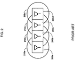
- FIG. 2 is an array of typical antenna and their resulting omni-directional signal patterns
- FIG. 3A is a depiction of an antenna array and resulting signal pattern according to one embodiment of the invention.
- FIGS. 3B-3C are illustrations of other embodiments of antenna arrays and resulting signal patterns in accordance with the principles of the invention.
- FIG. 4 illustrates one embodiment of a super-array comprised of four individual beam-forming arrays, each of which is comprised of a plurality of high-frequency RF antennas;
- FIG. 5 is one embodiment of a communication system for carrying out one or more aspect of the invention.
- One aspect of the invention is to provide a high-frequency RF antenna array for each transmitter. Through the use of appropriate signal processing interference between the individual antennas comprising the array is eliminated in favor of constructive interference that beams the resulting RF signal pattern.
- the optimal frequency of the antenna array is in the 60 GHz band. In another embodiment, the optimal frequencies of the antenna array are between 57 GHz and 95 GHz. Regardless of frequency, in certain embodiments the individual antennas which comprise the array all are optimized to operate at approximately the same frequency and with a signal phase controlled by signal processing to enable the antennae to operate in conjunction with one another.
- the beam-forming characteristics of an antenna array are based in part on both the physical antenna pattern comprising the array, as well as the physical pattern of the individual antennas. As such, numerous antenna configurations and array patterns would be consistent with the principles of the invention.
- Another aspect is to enable a plurality of aforementioned beam-forming arrays to be used for parallel transmission.
- this is done by forming a super-array comprised of a plurality of individual beam-forming arrays of high-frequency RF antennas.
- Parallel data transmission using such a super-array may be used to increase both transmission distance, as well as the data transmission rate.
- Individual point to point transmissions can easily achieve >2 Gbps at up to 20 meters at very low power ( ⁇ 10 dBm).
- the invention enables the parallel RF transmission of data in the 60 GHz band at multi-Gigabit per second (Gbps) data rates without the need to change frequency on the radio transmitters, thus contributing to a low cost implementation.
- Gbps multi-Gigabit per second
- parallel transmission is enabled by splitting or dividing an incoming data stream into multiple data streams and wirelessly broadcasting them in parallel from point-to-point.
- a parallel incoming data stream is multiplexed into 1 or more serial streams which is then wirelessly broadcast point-to-point.
- the transmission point is comprised of a super-array of individual beam-forming antenna arrays.
- the receiving point may be comprised of a corresponding series of receiving antennas, after which data stream can be recombined.
- the received data streams maybe demultiplexed, re-combined and re-aligned to a parallel data stream.
- parallel transmission is enabled using 60 GHz band transmissions.
- the super-array may be a one-dimensional array, in other embodiments it may be a two-dimensional array.
- the beam forming capacity of the array may be orthogonal to the plane of the array of the individual antennae.
- beam-forming whether in one-dimension or two-dimensions, need not be at right angles or orthogonal, respectively.
- the beams formed minimize interference when parallel to one another. However, they need not be at right angles to the antennas that comprise the array. Rather, the beams can be at any angle to the array that can be achieved using, for example, antenna steering.
- the beams formed by the array need not be orthogonal to the plane in which the individual antennas reside.
- Another aspect of the invention is to print an embodiment of the aforementioned super-array atop a substrate attached to an integrated circuit (IC) of a transmitter or receiver. While typically it would not be possible to mount multiple antennas on an IC due to the resulting interference and/or size issues discussed above, the directionality of high frequency transmission systems, such as in the 60 GHz band, enables the close placement of individual antennas without incurring the signal interference issues of the prior art.
- IC integrated circuit
- antennae are typically sized at one-quarter wavelength (lambda/4) and multiple antennas can be placed at half-wavelengths apart (lambda/2), millimeter wavelength implementations allows antennas to be placed a few millimeters apart and many antennae can be place in an area of only a few millimeters squared. The exact spacing is determined by the frequency of the transmitter and the nature of the antennae employed.
- FIG. 1 depicts a typical RF antenna 100 of the prior art and its resulting omni-directional signal pattern 110 .
- FIG. 2 attempting to use an array of antennas 100 would cause large signal distortions and interferences due to their overlapping signal propagations.
- FIG. 2 depicts what the signal propagation of a series of omni-directional antennas 200 a - 200 d were placed in parallel. Signal patterns 210 a - 210 d would severely overlap, as shown in FIG. 2 .
- One way this has been avoided by the prior art is for antennas 200 a - 200 d each to transmit on different frequencies and/or vary the phase of the transmissions.
- each of these solutions result in higher costs of manufacture due to more complex hardware and/or software.
- antenna array 300 depicted is one embodiment of a 60 GHz band antenna array 300 and its resulting signal pattern 310 .
- array 300 of FIG. 3A is shown as comprising five individual antennas, it should equally be appreciated that any other number of antennas greater than one may similarly be used to form array 300 .
- antenna array 300 may transmit at frequencies above the 60 GHz band, such as up to 95 GHz.
- the orientation of high-frequency array 300 results in a beam-formed RF signal 310 .
- individual antennas may be placed close together due to the short wavelengths and subsequent antennae implementations to produce a directed beam minimal interference between the individual antennas. This is made possible by the fact that the shorter wavelength of higher frequency signals allows smaller antennas to be used.
- Directional signals reduce adjacent interferences, improve communication security, provide better QoS, have a higher bit-rate per area and are more energy efficient.
- beam-formed signal 310 may have other directionality than what is depicted in FIG. 3A based on the physical placement of the antennas which comprise array 300 , as well as the physical patterns of the individual antennas themselves.
- signal processing software may further be used to alter or modify the characteristics of beam-formed signal 310 .
- FIGS. 3B-3C depict additional embodiments thereof.
- high frequency RF antenna array 320 is depicted as being comprised of 3 separate individual antennas placed in close proximity to each other resulting in beam-formed signal 330 .
- FIG. 3C depicts a high frequency RF antenna array 340 as being comprised of 6 separate individual antennas placed in close proximity to each other resulting in beam-formed signal 340 .
- FIG. 4 depicted is one embodiment of a super-array 400 comprised of four individual beam-forming arrays 410 a - 410 d , each of which is comprised of a plurality of high-frequency RF antennas.
- the individual antennas which comprise array 410 a - 410 d may be placed within approximately 1 ⁇ 2 wavelengths to one another. It should also be appreciated that numerous other configurations of the individual antennas would be consistent with the principles of the invention.
- one aspect of the invention is to enable high-speed parallel data transmission using a super-array, such as super-array 400 to increase both transmission distance, as well as the data transmission rate.
- array 400 may be used to transmit beam-formed signals 420 a - 420 d in the 60 GHz band.
- the parallel transmission of signals 420 a - 420 d is enabled by splitting or dividing an incoming data stream (not shown) into multiple data streams and wirelessly broadcasting them from super-array 400 .
- super-array 400 is a one-dimensional array, in other embodiments it may be a two-dimensional array.
- super-array 400 is imprinted on a substrate attached to an integrated circuit (IC) of a transmitter.
- IC integrated circuit
- FIG. 5 illustrates a simplified schematic of a system 500 for carrying out on or more aspect of one embodiment of the invention.
- a data source 500 provides a data stream to a data splitting module 520 .
- the data source is a high bit rate source, such as a high definition video source.
- data splitting module may be any combination of hardware and software capable of dividing an incoming data stream into separate data streams.
- transmitter array 530 is comprised of four individual beam-forming sub-arrays (e.g., arrays 410 a - 410 d ), each of which is in turn comprised of a plurality of high-frequency RF antennas.
- four frequency-optimized individual antennas, each of a size of approximately ⁇ /4, are spaced at distance of approximately ⁇ /2 in an area the size of the wavelength, ⁇ squared which comprise the transmitter array 530 .
- the transmitter array 530 may be printed on the substrate of an integrated circuit. It should also be appreciated that the transmitter array 530 may be comprised of greater or fewer sub-arrays.
- high-speed parallel data transmission is made possible by transmitting a high frequency signal 550 between the transmitter array 530 and a corresponding receiver array 540 .
- signal 550 is in the 60 GHz band, it may similarly be in a higher frequency band as well (e.g., 57 GHz to 95 GHz).
- this compatibility check may include having the transmitter array 530 send out a high frequency signal containing a unique pattern of on/off values. Upon receiving this pattern, the receiver array 540 may then acknowledge signal.
- signal 550 may travel a distance of between a few millimeters to several meters, depending on power, modulation, antennae arrangement, signal processing, etc.
- the receiver array 540 may be comprised four individual beam-forming sub-arrays each of which is in turn comprised of a plurality of high-frequency RF antennas.
- the individual antennas which comprise the receiver array 540 may be placed within between about 1 ⁇ 2 wavelength each other.
- the receiver array 540 may be printed on the substrate of an integrated circuit. It should also be appreciated that the receiver array 540 may be comprised of greater or fewer sub-arrays.
- the data stream can be recombined by module 560 and provided to a data sink 570 , as shown in FIG. 5 .
- the data sink 570 can be any data destination, such as high definition television, computer hard drive, digital video recorder, PDA, DVD player, etc.
- parallel transmission of signal 550 as depicted in FIG. 5 enables the transmission of multi-Gigabit per second data rates using 60 GHz band transmissions.
Abstract
Description
Claims (25)
Priority Applications (7)
| Application Number | Priority Date | Filing Date | Title |
|---|---|---|---|
| US11/416,857 US7733287B2 (en) | 2005-07-29 | 2006-05-02 | Systems and methods for high frequency parallel transmissions |
| KR1020087002275A KR101248333B1 (en) | 2005-07-29 | 2006-07-24 | Systems and methods for high frequency parallel transmissions |
| MX2008001182A MX2008001182A (en) | 2005-07-29 | 2006-07-24 | Systems and methods for high frequency parallel transmissions. |
| PCT/US2006/029004 WO2007016154A2 (en) | 2005-07-29 | 2006-07-24 | Systems and methods for high frequency parallel transmissions |
| CA2616349A CA2616349C (en) | 2005-07-29 | 2006-07-24 | Systems and methods for high frequency parallel transmissions |
| JP2008524098A JP4918090B2 (en) | 2005-07-29 | 2006-07-24 | System and method for high frequency parallel transmission |
| EP06788539.2A EP1911123B1 (en) | 2005-07-29 | 2006-07-24 | Systems and methods for high frequency parallel transmissions |
Applications Claiming Priority (2)
| Application Number | Priority Date | Filing Date | Title |
|---|---|---|---|
| US70417905P | 2005-07-29 | 2005-07-29 | |
| US11/416,857 US7733287B2 (en) | 2005-07-29 | 2006-05-02 | Systems and methods for high frequency parallel transmissions |
Publications (2)
| Publication Number | Publication Date |
|---|---|
| US20070024506A1 US20070024506A1 (en) | 2007-02-01 |
| US7733287B2 true US7733287B2 (en) | 2010-06-08 |
Family
ID=37693756
Family Applications (1)
| Application Number | Title | Priority Date | Filing Date |
|---|---|---|---|
| US11/416,857 Expired - Fee Related US7733287B2 (en) | 2005-07-29 | 2006-05-02 | Systems and methods for high frequency parallel transmissions |
Country Status (7)
| Country | Link |
|---|---|
| US (1) | US7733287B2 (en) |
| EP (1) | EP1911123B1 (en) |
| JP (1) | JP4918090B2 (en) |
| KR (1) | KR101248333B1 (en) |
| CA (1) | CA2616349C (en) |
| MX (1) | MX2008001182A (en) |
| WO (1) | WO2007016154A2 (en) |
Cited By (1)
| Publication number | Priority date | Publication date | Assignee | Title |
|---|---|---|---|---|
| US9692476B2 (en) | 2012-04-25 | 2017-06-27 | 3M Innovative Properties Company | Wireless connectors |
Families Citing this family (31)
| Publication number | Priority date | Publication date | Assignee | Title |
|---|---|---|---|---|
| US5914613A (en) | 1996-08-08 | 1999-06-22 | Cascade Microtech, Inc. | Membrane probing system with local contact scrub |
| US6256882B1 (en) | 1998-07-14 | 2001-07-10 | Cascade Microtech, Inc. | Membrane probing system |
| US6914423B2 (en) | 2000-09-05 | 2005-07-05 | Cascade Microtech, Inc. | Probe station |
| US6965226B2 (en) | 2000-09-05 | 2005-11-15 | Cascade Microtech, Inc. | Chuck for holding a device under test |
| DE20114544U1 (en) | 2000-12-04 | 2002-02-21 | Cascade Microtech Inc | wafer probe |
| WO2003052435A1 (en) | 2001-08-21 | 2003-06-26 | Cascade Microtech, Inc. | Membrane probing system |
| US6777964B2 (en) * | 2002-01-25 | 2004-08-17 | Cascade Microtech, Inc. | Probe station |
| US7352258B2 (en) * | 2002-03-28 | 2008-04-01 | Cascade Microtech, Inc. | Waveguide adapter for probe assembly having a detachable bias tee |
| US7492172B2 (en) | 2003-05-23 | 2009-02-17 | Cascade Microtech, Inc. | Chuck for holding a device under test |
| US7057404B2 (en) | 2003-05-23 | 2006-06-06 | Sharp Laboratories Of America, Inc. | Shielded probe for testing a device under test |
| US7250626B2 (en) | 2003-10-22 | 2007-07-31 | Cascade Microtech, Inc. | Probe testing structure |
| JP2007517231A (en) | 2003-12-24 | 2007-06-28 | カスケード マイクロテック インコーポレイテッド | Active wafer probe |
| US7187188B2 (en) | 2003-12-24 | 2007-03-06 | Cascade Microtech, Inc. | Chuck with integrated wafer support |
| US7176705B2 (en) * | 2004-06-07 | 2007-02-13 | Cascade Microtech, Inc. | Thermal optical chuck |
| DE202005021435U1 (en) | 2004-09-13 | 2008-02-28 | Cascade Microtech, Inc., Beaverton | Double-sided test setups |
| US7656172B2 (en) * | 2005-01-31 | 2010-02-02 | Cascade Microtech, Inc. | System for testing semiconductors |
| US7535247B2 (en) | 2005-01-31 | 2009-05-19 | Cascade Microtech, Inc. | Interface for testing semiconductors |
| US7593704B2 (en) * | 2005-03-31 | 2009-09-22 | Georgia Tech Research Corporation | Receiver assembly and method for multi-gigabit wireless systems |
| US8014416B2 (en) * | 2006-02-14 | 2011-09-06 | Sibeam, Inc. | HD physical layer of a wireless communication device |
| US7403028B2 (en) | 2006-06-12 | 2008-07-22 | Cascade Microtech, Inc. | Test structure and probe for differential signals |
| US7723999B2 (en) | 2006-06-12 | 2010-05-25 | Cascade Microtech, Inc. | Calibration structures for differential signal probing |
| US7764072B2 (en) | 2006-06-12 | 2010-07-27 | Cascade Microtech, Inc. | Differential signal probing system |
| US7876114B2 (en) | 2007-08-08 | 2011-01-25 | Cascade Microtech, Inc. | Differential waveguide probe |
| US7936240B2 (en) * | 2007-08-16 | 2011-05-03 | Simon Fraser University | Lithographically controlled curvature for MEMS devices and antennas |
| US7888957B2 (en) | 2008-10-06 | 2011-02-15 | Cascade Microtech, Inc. | Probing apparatus with impedance optimized interface |
| US8410806B2 (en) | 2008-11-21 | 2013-04-02 | Cascade Microtech, Inc. | Replaceable coupon for a probing apparatus |
| US8319503B2 (en) | 2008-11-24 | 2012-11-27 | Cascade Microtech, Inc. | Test apparatus for measuring a characteristic of a device under test |
| JP5675165B2 (en) * | 2010-05-13 | 2015-02-25 | 三菱電機株式会社 | Data transmission system for satellite communications |
| JP6499665B2 (en) * | 2014-08-18 | 2019-04-10 | パナソニック株式会社 | MIMO training method and radio apparatus |
| US10311264B1 (en) * | 2018-04-30 | 2019-06-04 | Xerox Corporation | Printed RFID tag antenna array with interfering subarrays |
| US11658960B2 (en) * | 2019-07-18 | 2023-05-23 | Nitesh Ratnakar | Apparatus and method for network security for devices in an Internet of Things (IOT) network |
Citations (16)
| Publication number | Priority date | Publication date | Assignee | Title |
|---|---|---|---|---|
| US2418124A (en) * | 1942-09-07 | 1947-04-01 | Standard Telephones Cables Ltd | Directive antenna array |
| US4933679A (en) * | 1989-04-17 | 1990-06-12 | Yury Khronopulo | Antenna |
| US5523764A (en) | 1994-08-23 | 1996-06-04 | Cornell Research Foundation Inc. | Electronic beam steering of active arrays with phase-locked loops |
| US6268781B1 (en) * | 1997-09-10 | 2001-07-31 | Hughes Electronics Corporation | Planar waveguide-to-stripline adapter |
| US6445346B2 (en) * | 2000-04-27 | 2002-09-03 | Sarnoff Corporation | Planar polarizer feed network for a dual circular polarized antenna array |
| US6529166B2 (en) * | 2000-09-22 | 2003-03-04 | Sarnoff Corporation | Ultra-wideband multi-beam adaptive antenna |
| US20040085250A1 (en) * | 2001-11-07 | 2004-05-06 | Tillery James K. | Linearly-polarized dual-band base-station antenna |
| US6870503B2 (en) | 2002-11-19 | 2005-03-22 | Farrokh Mohamadi | Beam-forming antenna system |
| US6876336B2 (en) * | 2003-08-04 | 2005-04-05 | Harris Corporation | Phased array antenna with edge elements and associated methods |
| US6947008B2 (en) * | 2003-01-31 | 2005-09-20 | Ems Technologies, Inc. | Conformable layered antenna array |
| US20060001572A1 (en) * | 2004-06-30 | 2006-01-05 | Gaucher Brian P | Apparatus and method for constructing and packaging printed antenna devices |
| US7292831B2 (en) * | 2002-03-29 | 2007-11-06 | National Institute Of Information And Communications Technology | Radio communicate method and system |
| US7365699B2 (en) * | 2004-05-19 | 2008-04-29 | New Jersey Institute Of Technology | Independently center fed dipole array |
| US7379515B2 (en) * | 1999-11-24 | 2008-05-27 | Parkervision, Inc. | Phased array antenna applications of universal frequency translation |
| US20080174510A1 (en) * | 2007-01-19 | 2008-07-24 | Northrop Grumman Systems Corporation | Radome for endfire antenna arrays |
| US7417440B2 (en) * | 2003-09-15 | 2008-08-26 | Rapiscan Security Products, Inc. | Methods and systems for the rapid detection of concealed objects |
Family Cites Families (10)
| Publication number | Priority date | Publication date | Assignee | Title |
|---|---|---|---|---|
| JP2580604B2 (en) * | 1987-06-19 | 1997-02-12 | 三菱電機株式会社 | Microwave integrated circuit with integrated antenna |
| JP3130575B2 (en) * | 1991-07-25 | 2001-01-31 | 日本電気株式会社 | Microwave and millimeter wave transceiver module |
| US5754948A (en) * | 1995-12-29 | 1998-05-19 | University Of North Carolina At Charlotte | Millimeter-wave wireless interconnection of electronic components |
| JPH10135732A (en) * | 1996-10-31 | 1998-05-22 | Hitachi Ltd | Slave unit antenna for indoor radio lan |
| JP3709639B2 (en) * | 1996-12-19 | 2005-10-26 | ソニー株式会社 | Signal transmitting / receiving apparatus and method |
| EP0889542A1 (en) * | 1997-06-30 | 1999-01-07 | Sony International (Europe) GmbH | Wide band printed phase array antenna for microwave and mm-wave applications |
| US6289237B1 (en) * | 1998-12-22 | 2001-09-11 | University Of Pittsburgh Of The Commonwealth System Of Higher Education | Apparatus for energizing a remote station and related method |
| JP4303373B2 (en) * | 1999-09-14 | 2009-07-29 | 株式会社日立コミュニケーションテクノロジー | Wireless base station equipment |
| JP3957059B2 (en) * | 2001-06-08 | 2007-08-08 | シャープ株式会社 | Terminal device for optical communication system and base station |
| JP4117138B2 (en) * | 2002-02-26 | 2008-07-16 | ソフトバンクテレコム株式会社 | CDMA base station apparatus |
-
2006
- 2006-05-02 US US11/416,857 patent/US7733287B2/en not_active Expired - Fee Related
- 2006-07-24 WO PCT/US2006/029004 patent/WO2007016154A2/en active Application Filing
- 2006-07-24 JP JP2008524098A patent/JP4918090B2/en not_active Expired - Fee Related
- 2006-07-24 MX MX2008001182A patent/MX2008001182A/en active IP Right Grant
- 2006-07-24 CA CA2616349A patent/CA2616349C/en not_active Expired - Fee Related
- 2006-07-24 EP EP06788539.2A patent/EP1911123B1/en not_active Expired - Fee Related
- 2006-07-24 KR KR1020087002275A patent/KR101248333B1/en not_active IP Right Cessation
Patent Citations (17)
| Publication number | Priority date | Publication date | Assignee | Title |
|---|---|---|---|---|
| US2418124A (en) * | 1942-09-07 | 1947-04-01 | Standard Telephones Cables Ltd | Directive antenna array |
| US4933679A (en) * | 1989-04-17 | 1990-06-12 | Yury Khronopulo | Antenna |
| US5523764A (en) | 1994-08-23 | 1996-06-04 | Cornell Research Foundation Inc. | Electronic beam steering of active arrays with phase-locked loops |
| US6268781B1 (en) * | 1997-09-10 | 2001-07-31 | Hughes Electronics Corporation | Planar waveguide-to-stripline adapter |
| US7379515B2 (en) * | 1999-11-24 | 2008-05-27 | Parkervision, Inc. | Phased array antenna applications of universal frequency translation |
| US6445346B2 (en) * | 2000-04-27 | 2002-09-03 | Sarnoff Corporation | Planar polarizer feed network for a dual circular polarized antenna array |
| US6529166B2 (en) * | 2000-09-22 | 2003-03-04 | Sarnoff Corporation | Ultra-wideband multi-beam adaptive antenna |
| US20040085250A1 (en) * | 2001-11-07 | 2004-05-06 | Tillery James K. | Linearly-polarized dual-band base-station antenna |
| US7292831B2 (en) * | 2002-03-29 | 2007-11-06 | National Institute Of Information And Communications Technology | Radio communicate method and system |
| US7126554B2 (en) * | 2002-11-19 | 2006-10-24 | Farrokh Mohamadi | Integrated circuit waveguide |
| US6870503B2 (en) | 2002-11-19 | 2005-03-22 | Farrokh Mohamadi | Beam-forming antenna system |
| US6947008B2 (en) * | 2003-01-31 | 2005-09-20 | Ems Technologies, Inc. | Conformable layered antenna array |
| US6876336B2 (en) * | 2003-08-04 | 2005-04-05 | Harris Corporation | Phased array antenna with edge elements and associated methods |
| US7417440B2 (en) * | 2003-09-15 | 2008-08-26 | Rapiscan Security Products, Inc. | Methods and systems for the rapid detection of concealed objects |
| US7365699B2 (en) * | 2004-05-19 | 2008-04-29 | New Jersey Institute Of Technology | Independently center fed dipole array |
| US20060001572A1 (en) * | 2004-06-30 | 2006-01-05 | Gaucher Brian P | Apparatus and method for constructing and packaging printed antenna devices |
| US20080174510A1 (en) * | 2007-01-19 | 2008-07-24 | Northrop Grumman Systems Corporation | Radome for endfire antenna arrays |
Non-Patent Citations (5)
| Title |
|---|
| Alalusi presentation titled "A 60GHz Antenna Array Front-End in CMOS for Gigabit-per-second Indoor Mobile Applications" and located at the website http://bwrc.eecs.berkeley.edu/seminars/Seminars-Archive/Alalusi%20-3.21.03/Antenna%20Array%20Alalusi.ppt. * |
| Alalusi presentation titled "A 60GHz Antenna Array Front-End in CMOS for Gigabit-per-second Indoor Mobile Applications" and located at the website http://bwrc.eecs.berkeley.edu/seminars/Seminars—Archive/Alalusi%20-3.21.03/Antenna%20Array%20Alalusi.ppt. * |
| Antenna array Website http://www.analyzemath.com/antenna-tutorials/antenna-arrays.html. * |
| Antenna array Website http://www.analyzemath.com/antenna—tutorials/antenna—arrays.html. * |
| Dietrich, Jr. (Adaptive Arrays and Diversity Antenna Configurations for Handheld Wireless Communication Terminals; available at http://scholar.lib.vt.edu/theses/available/etd-04262000-15330030/unrestricted/). * |
Cited By (1)
| Publication number | Priority date | Publication date | Assignee | Title |
|---|---|---|---|---|
| US9692476B2 (en) | 2012-04-25 | 2017-06-27 | 3M Innovative Properties Company | Wireless connectors |
Also Published As
| Publication number | Publication date |
|---|---|
| WO2007016154A2 (en) | 2007-02-08 |
| EP1911123A4 (en) | 2011-04-27 |
| EP1911123B1 (en) | 2013-09-04 |
| JP2009504021A (en) | 2009-01-29 |
| KR20080036185A (en) | 2008-04-25 |
| CA2616349A1 (en) | 2007-02-08 |
| JP4918090B2 (en) | 2012-04-18 |
| KR101248333B1 (en) | 2013-04-01 |
| US20070024506A1 (en) | 2007-02-01 |
| CA2616349C (en) | 2014-05-20 |
| EP1911123A2 (en) | 2008-04-16 |
| MX2008001182A (en) | 2008-03-18 |
| WO2007016154A3 (en) | 2007-12-13 |
Similar Documents
| Publication | Publication Date | Title |
|---|---|---|
| US7733287B2 (en) | Systems and methods for high frequency parallel transmissions | |
| EP2022188B1 (en) | Millimeter-wave personal area network | |
| US7825864B2 (en) | Dual band WLAN antenna | |
| US7761061B2 (en) | Programmable antenna assembly and applications thereof | |
| US20120235881A1 (en) | Mm-wave phased array antenna and system integration on semi-flex packaging | |
| US20130210366A1 (en) | Antenna arrangement for vehicles for transmitting and receiving | |
| KR101182074B1 (en) | Mechanism to avoid interference and improve channel efficiency in mmwave wpans | |
| US20070040760A1 (en) | Directional antenna system with multi-use elements | |
| KR20090065229A (en) | Directional antenna, transmitter and receiver comprising the same | |
| US7750855B2 (en) | Compact polarization-sensitive and phase-sensitive antenna with directionality and multi-frequency resonances | |
| WO2005029641A1 (en) | An apparatus for controlling spacing of each element in an antenna array | |
| GB2526282A (en) | Selective antenna system combining phased array and lens devices | |
| KR20220127312A (en) | Antenna module having a multilayer impedance converter and electronic device including the same | |
| Fittipaldi et al. | IEEE 802.15. 3c medium access controller throughput for phased array systems | |
| TWI622227B (en) | Multiple non-orthogonal metallic receivers for a parabolic dish apparatus and system | |
| CN101233652A (en) | Systems and methods for high frequency parallel transmissions | |
| KR101927954B1 (en) | Beamforming antenna | |
| CN116683932A (en) | Signal communication terminal system and method thereof |
Legal Events
| Date | Code | Title | Description |
|---|---|---|---|
| AS | Assignment |
Owner name: SONY CORPORATION,JAPAN Free format text: ASSIGNMENT OF ASSIGNORS INTEREST;ASSIGNOR:HARDACKER, ROBERT;REEL/FRAME:017862/0207 Effective date: 20060501 Owner name: SONY ELECTRONIC INC.,NEW JERSEY Free format text: ASSIGNMENT OF ASSIGNORS INTEREST;ASSIGNOR:HARDACKER, ROBERT;REEL/FRAME:017862/0207 Effective date: 20060501 Owner name: SONY ELECTRONIC INC., NEW JERSEY Free format text: ASSIGNMENT OF ASSIGNORS INTEREST;ASSIGNOR:HARDACKER, ROBERT;REEL/FRAME:017862/0207 Effective date: 20060501 Owner name: SONY CORPORATION, JAPAN Free format text: ASSIGNMENT OF ASSIGNORS INTEREST;ASSIGNOR:HARDACKER, ROBERT;REEL/FRAME:017862/0207 Effective date: 20060501 |
|
| FPAY | Fee payment |
Year of fee payment: 4 |
|
| FEPP | Fee payment procedure |
Free format text: MAINTENANCE FEE REMINDER MAILED (ORIGINAL EVENT CODE: REM.) |
|
| LAPS | Lapse for failure to pay maintenance fees |
Free format text: PATENT EXPIRED FOR FAILURE TO PAY MAINTENANCE FEES (ORIGINAL EVENT CODE: EXP.) |
|
| STCH | Information on status: patent discontinuation |
Free format text: PATENT EXPIRED DUE TO NONPAYMENT OF MAINTENANCE FEES UNDER 37 CFR 1.362 |
|
| FP | Lapsed due to failure to pay maintenance fee |
Effective date: 20180608 |