EP1526323A2 - Carter d'un moteur - Google Patents
Carter d'un moteur Download PDFInfo
- Publication number
- EP1526323A2 EP1526323A2 EP04023941A EP04023941A EP1526323A2 EP 1526323 A2 EP1526323 A2 EP 1526323A2 EP 04023941 A EP04023941 A EP 04023941A EP 04023941 A EP04023941 A EP 04023941A EP 1526323 A2 EP1526323 A2 EP 1526323A2
- Authority
- EP
- European Patent Office
- Prior art keywords
- oil
- unit case
- engine unit
- housing
- passage
- Prior art date
- Legal status (The legal status is an assumption and is not a legal conclusion. Google has not performed a legal analysis and makes no representation as to the accuracy of the status listed.)
- Granted
Links
Images
Classifications
-
- F—MECHANICAL ENGINEERING; LIGHTING; HEATING; WEAPONS; BLASTING
- F01—MACHINES OR ENGINES IN GENERAL; ENGINE PLANTS IN GENERAL; STEAM ENGINES
- F01M—LUBRICATING OF MACHINES OR ENGINES IN GENERAL; LUBRICATING INTERNAL COMBUSTION ENGINES; CRANKCASE VENTILATING
- F01M1/00—Pressure lubrication
- F01M1/16—Controlling lubricant pressure or quantity
-
- F—MECHANICAL ENGINEERING; LIGHTING; HEATING; WEAPONS; BLASTING
- F01—MACHINES OR ENGINES IN GENERAL; ENGINE PLANTS IN GENERAL; STEAM ENGINES
- F01M—LUBRICATING OF MACHINES OR ENGINES IN GENERAL; LUBRICATING INTERNAL COMBUSTION ENGINES; CRANKCASE VENTILATING
- F01M1/00—Pressure lubrication
- F01M1/02—Pressure lubrication using lubricating pumps
-
- F—MECHANICAL ENGINEERING; LIGHTING; HEATING; WEAPONS; BLASTING
- F01—MACHINES OR ENGINES IN GENERAL; ENGINE PLANTS IN GENERAL; STEAM ENGINES
- F01M—LUBRICATING OF MACHINES OR ENGINES IN GENERAL; LUBRICATING INTERNAL COMBUSTION ENGINES; CRANKCASE VENTILATING
- F01M11/00—Component parts, details or accessories, not provided for in, or of interest apart from, groups F01M1/00 - F01M9/00
- F01M11/02—Arrangements of lubricant conduits
-
- F—MECHANICAL ENGINEERING; LIGHTING; HEATING; WEAPONS; BLASTING
- F01—MACHINES OR ENGINES IN GENERAL; ENGINE PLANTS IN GENERAL; STEAM ENGINES
- F01M—LUBRICATING OF MACHINES OR ENGINES IN GENERAL; LUBRICATING INTERNAL COMBUSTION ENGINES; CRANKCASE VENTILATING
- F01M1/00—Pressure lubrication
- F01M1/02—Pressure lubrication using lubricating pumps
- F01M2001/0284—Pressure lubrication using lubricating pumps mounting of the pump
Definitions
- the present invention relates to an engine unit case. More particularly, the present, invention pertains to an engine unit case including a regulator valve for adjusting discharge pressure of an oil pump.
- Engines include a cylinder head, a cylinder block, a crankcase, and an oil pan.
- the crankcase serves as an engine unit case.
- Engines may include the cylinder head, the cylinder block, the crankcase, an upper oil pan, and a lower oil pan. With this construction, the crankcase and the upper oil pan serve as the engine unit case.
- the engine unit case includes an oil pump for pressure feeding the oil to each portion in the engine for the lubrication and the cooling, and a regulator valve for adjusting the discharge pressure from the oil pump.
- An layout of the oil pump, the regulator valve, and oil paths (oil ports) in communication with the oil pump and the regulator valve impacts on reducing the size, reducing the weight, reducing the number of parts, and simplifying the machining and assembling of the engine unit case.
- the relief oil discharged from the regulator valve drops in the oil pan provided at the bottom of the engine unit case.
- the oil hits the surface of the oil in the oil pan to generate the foam at-the oil surface.
- the regulator valve In case the regulator valve is assembled to the engine unit case with a tightening means, it is required to provide an oil sealing member and a tightening member, or the like, at the fitting plane on the engine unit case for assembling the regulator value. In other words, the construction of the engine unit case assumes complicated and the number of the parts increases. Further, because the regulator valve is projected from the fitting plane, the regulator value is likely to be affected by the engine vibration, thus it is required to improve the vibration resistance thereof. In order to increase the vibration resistance performance, it is required to increase the thickness of the wall around the fitting plane or to provide a reinforcement rib for improving the fitting rigidity, which increases the weight of the engine unit case, and thus to increase the weight of the engine per se.
- JPH05(1993)-10721U discloses the construction that an oil pipe is connected to an oil discharge port of the regulator valve so that the relief oil is directly returned to the oil pan in order to prevent the air mixture in the oil.
- JPH08(1996)-484Y2 discloses the construction for covering the surroundings of the discharge port of the relief oil of the regulator valve with a division wall provided either at the engine block (i.e., crankcase) or the oil pan.
- JPH10(1998)-141039A discloses the construction that includes the regulator valve positioned between mating faces of the engine block and the oil pan, and the relief oil is directly returned to a suction passage of the oil pump without being through the external space.
- the foregoing construction requires the complicated oil path (port) for both the engine block and the oil pan and complicated oil-sealing member at joining surfaces between the engine block and the port and between the oil pan and the port.
- an engine unit case which includes a housing configured to be assembled to a cylinder block of an engine, an oil pump provided at the housing, and a pressure adjusting mechanism for adjusting discharge pressure of the oil pump.
- the housing is unitarily formed with a pump chamber of the oil pump and a body of the pressure adjusting mechanism.
- the body of the pressure adjusting mechanism is unitarily formed with the housing of the engine unit case, the pressure adjusting mechanism tightening member and the sealing member at the fitting plane are not necessary, which prevents the tightening defect and the sealing defect.
- the influence by the engine vibration can be reduced, and it is not necessary to increase the wall thickness at the installing portion and to provide the reinforcement rib in order to increase the fitting rigidity.
- the number of the parts can be reduced, the machining and the assembling can be simplified, and the weight and the size of the engine unit case can be reduced.
- the relief passage of the pressure adjusting mechanism directly opens to and is in communication with the suction port of the pump chamber, the oil relieved from the pressure adjusting mechanism is directly returned to the suction port of the oil pump.
- the foaming on the oil caused by the relieved oil hitting the oil surface of the oil reserved in the oil pan can be securely prevented.
- the relief passage serves as the rib between the engine unit case and the pressure adjusting mechanism, the fitting rigidity of the pressure adjusting mechanism can be increased.
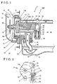
- Fig. 1 is a longitudinal cross-sectional view of a housing 20 including a regulator valve 50 and an oil pump 10.
- Fig. 2 is a cross-sectional view taken on line II-II of Fig. 1.
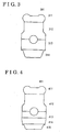
- Fig. 3 is a schematic view of an engine 301 including a cylinder head 311, a cylinder block 312, a crankcase 313, and an oil pan 314, wherein the crankcase 313 corresponds to the engine unit case 120.
- Fig. 4 a schematic view of an engine 401 including a cylinder head 411, a cylinder block 412, a crankcase 413, an upper oil pan 414, and a lower oil pan 415, wherein the crankcase 413 and the upper oil pan 414 corresponds to the engine unit case 120.
- an engine 301 includes a cylinder head 311, a cylinder block 312, a crankcase 313, and an oil pan 314.
- the crankcase 313 serves as an engine unit case 120 (shown in Fig. 1).
- an engine 401 includes a cylinder head 411, a cylinder block 412, a crankcase 413, an upper oil pan 414, and a lower oil pan 415.
- the crankcase 413 and the upper oil pan 414 serves as the engine unit case 120.
- the construction of the present invention can be applied to the both crankcase 413 and the upper oil pan 414.
- a pump chamber 13 accommodating a drive rotor 11 and a driven rotor 12 of the oil pump 10 is positioned at front end side (i.e., left side of Fig. 1) of the housing 20.
- the pump chamber 13 is defined by a concave portion 13a unitarily formed at the front end of the housing 20, and a cover 14 fixed to the housing 20 via bolts 30 for covering the concave portion 13a.
- the pump chamber 13 includes a suction port 15 for sucking the oil and a discharge port 16 for discharging the oil.
- the suction port 15 is in communication with a suction passage 21 for sucking the oil reserved in an oil pan 70 (314, 415) provided at the bottom portion of the engine via an oil strainer 60.
- the suction passage 21 is arranged in parallel with a back and forth direction of the engine 1.
- the discharge port 16 is in communication with a discharge passage 22 for feeding the oil to portions of the engine 1.
- the discharge passage 22 is arranged in parallel with the back and forth direction of the engine 1.
- An introducing passage 23 configured to be introduced with the hydraulic pressure (i.e., discharge pressure) of the oil flowing in the discharge passage 22 is formed at a portion of the discharge passage 22.
- the introducing passage 23 is arranged in parallel with the top-bottom direction of the engine 1.
- a cylinder 51 is formed at a first end (i.e., bottom side of Fig. 1) of the introducing passage 23.
- the cylinder 51 accommodates a valve (i.e., serving as a relief valve) 52 configured to start opening when the hydraulic pressure reaches a predetermined hydraulic pressure (i.e.; discharge pressure) of the oil flowing in the discharge passage 22 for controlling the discharge pressure approximately at a predetermined pressure.
- the cylinder 51 is arranged in parallel with the top-bottom direction of the engine 1.
- a body 54 including the cylinder 51 is unitarily formed with the housing 20.
- the tightening member; for the regulator valve 50 serving as the pressure adjusting mechanism and the sealing member at the fitting plane are not required, and tightening defects and sealing defects can be prevented. Further, the influence of the engine vibration can be reduced and it is not required : to increase the thickness of the wall at the fitting plane and to provide the reinforcement rib in order to increase the installation rigidity.
- Two relief holes 56 are formed on the lateral surface of the cylinder 51 for establishing the communication between the introducing passage 23 and a leading passage (relief passage) 24 upon the opening of the valve 52. Each relief hole 56 is in communication with the suction port 15 via the leading passage (relief passage) 24.
- the leading passage 24 is arranged in parallel with the back and forth direction of the engine 1.
- the cylinder 51 is arranged vertical to the discharge passage 22 and the leading passage 24 respectively.
- the leading passage 24 is in communication with the suction port 15 and arranged in parallel with the suction passage 21.
- the cylinder 51 accommodates the valve 52 opening and closing to control the communication between the introducing passage 23 and the leading passage 24 and a spring 53 for biasing the valve 52 to close the introducing passage 23.
- a plug 55 is capped on a first end of the cylinder 51 and a first end of the spring is engaged at the first end of the cylinder 51.
- the regulator valve 50 includes the cylinder 51, the valve 52, the spring 53, the body 54; and the plug 55.
- each shaft center of the regulator valve 50, the leading passage 24 (i.e., the relief passage), the suction passage 21 of the oil pump, and the discharge passage 22 of the oil pump is arranged either in parallel with the top-bottom direction of the engine 1 or the back and forth direction of the engine 1. Accordingly the machining and the assembling direction can be arranged either in the, back and forth direction or the top-bottom direction of the engine 1, which simplifies the machining process and the assembling process.
- the oil pump 10 includes a pump rotor having the drive rotor 11 fitted into a shaft 19 and the driven rotor 12 driven by the drive rotor 11.
- An intermediate portion of the shaft 19 is slidably supported by a penetration hole 14a formed at the cover 14.
- a sprocket 17 for transmitting the rotational driving force from the driving shaft of the engine 1 is fixed at a first end (i.e., left side of Fig. 1) of the shaft 19 via a nut 18.
- a second end side of the shaft 19 is rotatably supported by a bearing hole 13b opening to the concave portion 13a.
- the oil pan 70 for reserving the oil is provided at the bottom of the housing 20.
- a suction port 62 is positioned under the hydraulic surface of the reserved oil, and the oil strainer 60 is arranged to be in communication with the suction passage 21 in the oil pan 70.
- the oil strainer 60 is fixed to the housing 20 via the bolts 61, 61.
- inscribing gear type oil pump is applied in the foregoing embodiment, other types of oil pump such as a circumscribing gear type oil pump, or the like, may be applied.
- the oil strainer 60 is provided as a separate part from the engine unit case 120 20 and is connected to the housing 20 in the foregoing embodiment, the oil strainer may be unitarily formed with the housing 20. It is explicitly stated that all features disclosed in the description and/or the claims are intended to be disclosed separately and independently from each other for the purpose of original disclosure as well as for the purpose of restricting the claimed invention independent of the composition of the features in the embodiments and/or the claims. It is explicitly stated that all value ranges or indications of groups of entities disclose every possible intermediate value or intermediate entity for the purpose of orignal disclosure as well as for the purpose of restricting the claimed invention, in particular as limits of value ranges.
Landscapes
- Engineering & Computer Science (AREA)
- Mechanical Engineering (AREA)
- General Engineering & Computer Science (AREA)
- Lubrication Of Internal Combustion Engines (AREA)
Applications Claiming Priority (2)
| Application Number | Priority Date | Filing Date | Title |
|---|---|---|---|
| JP2003361014A JP2005127161A (ja) | 2003-10-21 | 2003-10-21 | エンジンユニットケース |
| JP2003361014 | 2003-10-21 |
Publications (3)
| Publication Number | Publication Date |
|---|---|
| EP1526323A2 true EP1526323A2 (fr) | 2005-04-27 |
| EP1526323A3 EP1526323A3 (fr) | 2005-05-25 |
| EP1526323B1 EP1526323B1 (fr) | 2006-11-29 |
Family
ID=34386483
Family Applications (1)
| Application Number | Title | Priority Date | Filing Date |
|---|---|---|---|
| EP04023941A Expired - Lifetime EP1526323B1 (fr) | 2003-10-21 | 2004-10-07 | Carter d'un moteur |
Country Status (5)
| Country | Link |
|---|---|
| US (1) | US7055489B2 (fr) |
| EP (1) | EP1526323B1 (fr) |
| JP (1) | JP2005127161A (fr) |
| CN (1) | CN2791265Y (fr) |
| DE (1) | DE602004003451T2 (fr) |
Families Citing this family (7)
| Publication number | Priority date | Publication date | Assignee | Title |
|---|---|---|---|---|
| JP4622776B2 (ja) * | 2005-09-22 | 2011-02-02 | スズキ株式会社 | オイルポンプ構造 |
| JP2007309234A (ja) * | 2006-05-19 | 2007-11-29 | Honda Motor Co Ltd | 内燃機関の潤滑装置 |
| DE202009000690U1 (de) * | 2009-01-16 | 2009-04-09 | Gather Industrie Gmbh | Rotationsverdrängerpumpe |
| AT507477B1 (de) * | 2009-12-03 | 2011-07-15 | Avl List Gmbh | Brennkraftmaschine mit einem zylinderkopf und einem zylinderblock |
| CN101858236A (zh) * | 2010-04-26 | 2010-10-13 | 隆鑫工业有限公司 | 通用内燃机的机油限压结构 |
| DE102013113757A1 (de) * | 2013-12-10 | 2015-06-11 | Dr. Ing. H.C. F. Porsche Aktiengesellschaft | Anordnung in einem Schmierölkreislauf einer Verbrennungskraftmaschine zum Pumpen von Schmieröl |
| CN111473232B (zh) * | 2020-04-29 | 2024-11-26 | 中国重型机械研究院股份公司 | 一种适用于回转件的速冷连续回油系统及其冷却方法 |
Family Cites Families (9)
| Publication number | Priority date | Publication date | Assignee | Title |
|---|---|---|---|---|
| US3443522A (en) * | 1967-07-10 | 1969-05-13 | Werner Schindler | Positive-displacement pump |
| DE3527024A1 (de) * | 1985-07-27 | 1987-01-29 | Bosch Gmbh Robert | Kettensaege mit einer tauchkolben-oelpumpe |
| JPH01249971A (ja) * | 1988-03-31 | 1989-10-05 | Suzuki Motor Co Ltd | トロコイドポンプ |
| US5085187A (en) * | 1991-03-11 | 1992-02-04 | Chrysler Corporation | Integral engine oil pump and pressure regulator |
| JPH0510721A (ja) | 1991-07-05 | 1993-01-19 | Iseki Tory Tech Inc | ターゲツトの距離補正方法及びターゲツト並びに距離補正装置及び前記距離補正装置を用いた掘進装置 |
| JP3228064B2 (ja) | 1994-04-18 | 2001-11-12 | 東陶機器株式会社 | 洗面化粧台 |
| JP3748643B2 (ja) | 1996-11-13 | 2006-02-22 | 本田技研工業株式会社 | 内燃機関の潤滑装置 |
| DE19927792A1 (de) * | 1998-06-23 | 2000-03-16 | Jidosha Kiki Co | Ölmpumpe |
| JP2001050411A (ja) * | 1999-08-04 | 2001-02-23 | Unisia Jecs Corp | リリーフ弁装置 |
-
2003
- 2003-10-21 JP JP2003361014A patent/JP2005127161A/ja active Pending
-
2004
- 2004-10-07 DE DE602004003451T patent/DE602004003451T2/de not_active Expired - Fee Related
- 2004-10-07 EP EP04023941A patent/EP1526323B1/fr not_active Expired - Lifetime
- 2004-10-15 US US10/964,719 patent/US7055489B2/en not_active Expired - Fee Related
- 2004-10-21 CN CNU2004201177354U patent/CN2791265Y/zh not_active Expired - Fee Related
Also Published As
| Publication number | Publication date |
|---|---|
| US7055489B2 (en) | 2006-06-06 |
| DE602004003451T2 (de) | 2007-09-27 |
| DE602004003451D1 (de) | 2007-01-11 |
| CN2791265Y (zh) | 2006-06-28 |
| EP1526323A3 (fr) | 2005-05-25 |
| JP2005127161A (ja) | 2005-05-19 |
| US20050081816A1 (en) | 2005-04-21 |
| EP1526323B1 (fr) | 2006-11-29 |
Similar Documents
| Publication | Publication Date | Title |
|---|---|---|
| US5743230A (en) | Balancer shaft supporting structure in engine | |
| US6142129A (en) | Breather apparatus for engine | |
| KR101309455B1 (ko) | 오일 펌프 장치 | |
| US8882480B2 (en) | Oil pump with air vent structure | |
| EP0990778B1 (fr) | Dispositif de refroidissement d'un système de moteur hors-bord | |
| US6311483B1 (en) | Apparatus for feeding secondary air to exhaust gas in engine | |
| CN1081727C (zh) | 立式发动机 | |
| EP1526323A2 (fr) | Carter d'un moteur | |
| US20070095335A1 (en) | Four-cycle engine and motorcycle comprising four-cycle engine | |
| EP1136677B1 (fr) | Moteur avec un arbre coudé relié à un arbre entraîné | |
| JP3435143B2 (ja) | オーバヘッドカム型v型エンジン | |
| US6192865B1 (en) | Fuel injection apparatus for vehicular engine | |
| CA2441362C (fr) | Circuit de lubrification pour moteur a combustion interne | |
| US7392780B2 (en) | Machine provided with pulsating oil pressure reducing device | |
| EP1182338B1 (fr) | Agencement des auxiliaires d'un moteur à combustion interne | |
| CA2439989C (fr) | Bloc-moteur pour vehicule a moteur a combustion interne | |
| EP0902176B1 (fr) | Dispositif d'aération pour un réservoir auxiliaire pour un ensemble de propulsion | |
| US9599063B2 (en) | Engine unit for vehicle | |
| JPH1162770A (ja) | 燃料噴射装置用高圧ポンプユニットの冷却構造 | |
| JP2020197156A (ja) | 自動車用のウォータポンプ一体式内燃機関 | |
| JP4289971B2 (ja) | ベーンポンプ | |
| JP2006266207A (ja) | エンジンの潤滑油供給装置 | |
| JP4416642B2 (ja) | 船外機 | |
| CN100416050C (zh) | 立式发动机 | |
| CN210141237U (zh) | 一种排气机构 |
Legal Events
| Date | Code | Title | Description |
|---|---|---|---|
| PUAI | Public reference made under article 153(3) epc to a published international application that has entered the european phase |
Free format text: ORIGINAL CODE: 0009012 |
|
| PUAL | Search report despatched |
Free format text: ORIGINAL CODE: 0009013 |
|
| AK | Designated contracting states |
Kind code of ref document: A2 Designated state(s): AT BE BG CH CY CZ DE DK EE ES FI FR GB GR HU IE IT LI LU MC NL PL PT RO SE SI SK TR |
|
| AX | Request for extension of the european patent |
Extension state: AL HR LT LV MK |
|
| AK | Designated contracting states |
Kind code of ref document: A3 Designated state(s): AT BE BG CH CY CZ DE DK EE ES FI FR GB GR HU IE IT LI LU MC NL PL PT RO SE SI SK TR |
|
| AX | Request for extension of the european patent |
Extension state: AL HR LT LV MK |
|
| 17P | Request for examination filed |
Effective date: 20051124 |
|
| GRAP | Despatch of communication of intention to grant a patent |
Free format text: ORIGINAL CODE: EPIDOSNIGR1 |
|
| AKX | Designation fees paid |
Designated state(s): DE FR GB |
|
| GRAS | Grant fee paid |
Free format text: ORIGINAL CODE: EPIDOSNIGR3 |
|
| RIN1 | Information on inventor provided before grant (corrected) |
Inventor name: KOBIYAMA, SHOJI,C/O AICHI MACHINE INDUSTRY CO., Inventor name: SUZUKI, FUMIYUKI,C/O AICHI MACHINE INDUSTRY CO., Inventor name: KUROKAWA, HIROYUKI,C/O INTELL.PROPERTY DEPARTMENT |
|
| GRAA | (expected) grant |
Free format text: ORIGINAL CODE: 0009210 |
|
| AK | Designated contracting states |
Kind code of ref document: B1 Designated state(s): DE FR GB |
|
| REG | Reference to a national code |
Ref country code: GB Ref legal event code: FG4D |
|
| REF | Corresponds to: |
Ref document number: 602004003451 Country of ref document: DE Date of ref document: 20070111 Kind code of ref document: P |
|
| ET | Fr: translation filed | ||
| PLBE | No opposition filed within time limit |
Free format text: ORIGINAL CODE: 0009261 |
|
| STAA | Information on the status of an ep patent application or granted ep patent |
Free format text: STATUS: NO OPPOSITION FILED WITHIN TIME LIMIT |
|
| 26N | No opposition filed |
Effective date: 20070830 |
|
| PG25 | Lapsed in a contracting state [announced via postgrant information from national office to epo] |
Ref country code: DE Free format text: LAPSE BECAUSE OF NON-PAYMENT OF DUE FEES Effective date: 20080501 |
|
| REG | Reference to a national code |
Ref country code: FR Ref legal event code: ST Effective date: 20080630 |
|
| PG25 | Lapsed in a contracting state [announced via postgrant information from national office to epo] |
Ref country code: FR Free format text: LAPSE BECAUSE OF NON-PAYMENT OF DUE FEES Effective date: 20071031 |
|
| GBPC | Gb: european patent ceased through non-payment of renewal fee |
Effective date: 20081007 |
|
| PG25 | Lapsed in a contracting state [announced via postgrant information from national office to epo] |
Ref country code: GB Free format text: LAPSE BECAUSE OF NON-PAYMENT OF DUE FEES Effective date: 20081007 |