EP1526316A1 - Radiale Drehdurchführung - Google Patents
Radiale Drehdurchführung Download PDFInfo
- Publication number
- EP1526316A1 EP1526316A1 EP04105011A EP04105011A EP1526316A1 EP 1526316 A1 EP1526316 A1 EP 1526316A1 EP 04105011 A EP04105011 A EP 04105011A EP 04105011 A EP04105011 A EP 04105011A EP 1526316 A1 EP1526316 A1 EP 1526316A1
- Authority
- EP
- European Patent Office
- Prior art keywords
- rotor
- rotary feedthrough
- sealing surfaces
- radial rotary
- radial
- Prior art date
- Legal status (The legal status is an assumption and is not a legal conclusion. Google has not performed a legal analysis and makes no representation as to the accuracy of the status listed.)
- Granted
Links
- 238000007789 sealing Methods 0.000 claims abstract description 64
- 239000000919 ceramic Substances 0.000 claims description 5
- 239000002184 metal Substances 0.000 claims description 2
- 229910052751 metal Inorganic materials 0.000 claims description 2
- 230000002093 peripheral effect Effects 0.000 claims description 2
- 230000005540 biological transmission Effects 0.000 abstract 1
- 239000012530 fluid Substances 0.000 description 22
- 230000002706 hydrostatic effect Effects 0.000 description 6
- 238000009434 installation Methods 0.000 description 5
- 238000010276 construction Methods 0.000 description 4
- 239000002826 coolant Substances 0.000 description 3
- 230000007423 decrease Effects 0.000 description 2
- 210000003746 feather Anatomy 0.000 description 2
- 238000003754 machining Methods 0.000 description 2
- 238000004519 manufacturing process Methods 0.000 description 2
- 238000009420 retrofitting Methods 0.000 description 2
- 230000007704 transition Effects 0.000 description 2
- 229910000851 Alloy steel Inorganic materials 0.000 description 1
- 229910000906 Bronze Inorganic materials 0.000 description 1
- 238000005299 abrasion Methods 0.000 description 1
- 239000000853 adhesive Substances 0.000 description 1
- 238000004026 adhesive bonding Methods 0.000 description 1
- 230000001070 adhesive effect Effects 0.000 description 1
- 230000006735 deficit Effects 0.000 description 1
- 238000007667 floating Methods 0.000 description 1
- 150000002739 metals Chemical class 0.000 description 1
- 238000000034 method Methods 0.000 description 1
- 238000005457 optimization Methods 0.000 description 1
- 238000005476 soldering Methods 0.000 description 1
- 239000010959 steel Substances 0.000 description 1
- 238000003860 storage Methods 0.000 description 1
- UONOETXJSWQNOL-UHFFFAOYSA-N tungsten carbide Chemical compound [W+]#[C-] UONOETXJSWQNOL-UHFFFAOYSA-N 0.000 description 1
- 238000003466 welding Methods 0.000 description 1
Images

Classifications
-
- F—MECHANICAL ENGINEERING; LIGHTING; HEATING; WEAPONS; BLASTING
- F16—ENGINEERING ELEMENTS AND UNITS; GENERAL MEASURES FOR PRODUCING AND MAINTAINING EFFECTIVE FUNCTIONING OF MACHINES OR INSTALLATIONS; THERMAL INSULATION IN GENERAL
- F16J—PISTONS; CYLINDERS; SEALINGS
- F16J15/00—Sealings
- F16J15/16—Sealings between relatively-moving surfaces
- F16J15/34—Sealings between relatively-moving surfaces with slip-ring pressed against a more or less radial face on one member
- F16J15/3464—Mounting of the seal
- F16J15/348—Pre-assembled seals, e.g. cartridge seals
- F16J15/3484—Tandem seals
-
- B—PERFORMING OPERATIONS; TRANSPORTING
- B65—CONVEYING; PACKING; STORING; HANDLING THIN OR FILAMENTARY MATERIAL
- B65G—TRANSPORT OR STORAGE DEVICES, e.g. CONVEYORS FOR LOADING OR TIPPING, SHOP CONVEYOR SYSTEMS OR PNEUMATIC TUBE CONVEYORS
- B65G33/00—Screw or rotary spiral conveyors
-
- B—PERFORMING OPERATIONS; TRANSPORTING
- B65—CONVEYING; PACKING; STORING; HANDLING THIN OR FILAMENTARY MATERIAL
- B65G—TRANSPORT OR STORAGE DEVICES, e.g. CONVEYORS FOR LOADING OR TIPPING, SHOP CONVEYOR SYSTEMS OR PNEUMATIC TUBE CONVEYORS
- B65G33/00—Screw or rotary spiral conveyors
- B65G33/08—Screw or rotary spiral conveyors for fluent solid materials
-
- F—MECHANICAL ENGINEERING; LIGHTING; HEATING; WEAPONS; BLASTING
- F16—ENGINEERING ELEMENTS AND UNITS; GENERAL MEASURES FOR PRODUCING AND MAINTAINING EFFECTIVE FUNCTIONING OF MACHINES OR INSTALLATIONS; THERMAL INSULATION IN GENERAL
- F16L—PIPES; JOINTS OR FITTINGS FOR PIPES; SUPPORTS FOR PIPES, CABLES OR PROTECTIVE TUBING; MEANS FOR THERMAL INSULATION IN GENERAL
- F16L27/00—Adjustable joints; Joints allowing movement
- F16L27/08—Adjustable joints; Joints allowing movement allowing adjustment or movement only about the axis of one pipe
- F16L27/087—Joints with radial fluid passages
-
- F—MECHANICAL ENGINEERING; LIGHTING; HEATING; WEAPONS; BLASTING
- F16—ENGINEERING ELEMENTS AND UNITS; GENERAL MEASURES FOR PRODUCING AND MAINTAINING EFFECTIVE FUNCTIONING OF MACHINES OR INSTALLATIONS; THERMAL INSULATION IN GENERAL
- F16L—PIPES; JOINTS OR FITTINGS FOR PIPES; SUPPORTS FOR PIPES, CABLES OR PROTECTIVE TUBING; MEANS FOR THERMAL INSULATION IN GENERAL
- F16L41/00—Branching pipes; Joining pipes to walls
Definitions
- the invention relates to a radial rotary feedthrough with at least one rotor and at least a fixed part, wherein the at least one rotor at least two axially spaced Has sealing surfaces and wherein between the fixed part and the rotor two slip rings are arranged with a total of at least two sealing surfaces, wherein the sealing surfaces of the sliding rings interact with the rotor sealing surfaces, and with at least one radial feed passage between the pairs of cooperating sealing surfaces.
- Rotary unions for fluids from a fixed to a rotating machine part are off known in the art.
- the technical problem to be solved by all rotary feedthroughs is to make a tight transition between two mutually rotating parts.
- the rotary feedthroughs known from the prior art are either axial feedthroughs, in which the fluid along the axis of rotation or parallel to it in the rotating machine part is transferred or radial rotary unions.
- Japanese Patent Publication JP 09196265 A shows such a radial rotary feedthrough, in which the fluid in a direction perpendicular to the axis of rotation of the rotating machine part of the fixed Machine part is transferred to the rotating part.
- the turning Part hereinafter also referred to as rotor
- two annular projections provided, the axial sealing surfaces have, the surface normal in the direction of the axis of rotation and the annular order rotate the axis of rotation of the rotor.
- the sealing surfaces of two sliding rings are based from.
- the sliding rings are secured against rotation with the rotor on the fixed part and their sealing surfaces are supported by themselves against a portion of the fixed part Pressed springs against the sealing surfaces of the rotor.
- the supply of the fluid takes place through a channel between the two sliding rings in a direction perpendicular to the axis of rotation of the Rotor. A leakage of the fluid is so with the help of the superimposed sealing surfaces of the Rotor and the two sliding rings and seals between the fixed part and the Prevents sliding rings.
- the rotary feedthrough known from JP 09196265 A has a very complex, voluminous Construction.
- the part carrying the Gleitdicht lake connected to a shaft consists of two axially spaced rotor rings, each associated with a sliding ring.
- the rotor rings must be sealed be fixed on the shaft.
- Each rotor ring is assigned its own sliding ring, which is not with rotated, but axially floating and resiliently biased on the shaft is arranged to regardless of any component and assembly tolerances always a dense edition of its Gleitdicht vin to ensure.
- the fixed part has for storage and support of the slip rings a radially inwardly projecting collar, which is arranged between the sliding rings and Press the sliding rings against the rotor ring via springs. This construction requires a lot Space in both the axial and in the radial direction.
- Radial (and also axial) rotary unions are used, among other things, for internal coolant supply used in machine tools.
- a disadvantage of these rotary joints is however in that they are relatively bulky and require space on a tool spindle. This is particularly disturbing in modern machining centers, which in any case accommodate tool magazines and turrets need.
- the present invention has the object, a radial rotary feedthrough design so that their installation in machining centers and Retrofitting to existing facilities is simplified and not on the low existing Place fails.
- a radial rotary feedthrough is provided with at least a rotor and at least one stationary part, wherein the at least one rotor has at least two sealing surfaces and wherein between the fixed part and the rotor two sliding rings are arranged with a total of at least two sealing surfaces, wherein the sealing surfaces the sliding rings cooperate with the rotor sealing surfaces, and with at least one radial feed passage between the pairs of cooperating sealing surfaces, the normal to the Have sealing surfaces of the rotor axially away from each other, the normal to the sealing surfaces of the Sliding rings are directed axially towards each other.
- the sliding sealing surfaces of the rotor on one and the same component be arranged and a particular advantage in this construction is that they are with a reduced axial height can be provided.
- the axial height i. H. the dimension the rotary feedthrough in a direction parallel to the axis of rotation of the rotor less than 40 mm, preferably less than 20 mm and particularly preferably 18 mm.
- the ratio of the diameter of the shaft to the axial height of Rotary feedthrough greater than 1, preferably greater than 1.5 and more preferably greater than 2 is. This ensures relatively low installation dimensions of the rotary unions even for large Shaft diameter.
- the maximum ratio between the radial thickness of the rotary feedthrough and the diameter of the shaft is less than 1/3, preferably less than 1/5 and especially preferably less than 1/6.
- the radial installation dimension holds even at relatively large Waves within limits.
- the rotor is made in one piece. This saves time and costs in the manufacture and especially in the assembly of the rotor.
- An embodiment of the invention is preferred in which the rotor has an annular projection has, whose end faces or parts thereof form the sealing surfaces. Because both sealing surfaces parts of the annular approach, less space is required than when using one support for each sealing surface.
- the annular approach in the axial direction be carried out relatively thin, since the sealing surfaces on the opposite cover surfaces of the annular approach, so that compensate for the forces exerted on the sealing surfaces forces. This also saves axial height.
- the axial height of the approach must be sufficient to be between the sliding surfaces formed by the end faces of the neck become, still a radial bore or a passage, which also a non-round, narrow Cross-section z. B. can have a long hole to accommodate.
- the rotor is designed in several parts, wherein he has at least one core and at least one deferred ring.
- the End faces of the pushed ring or parts thereof the sealing surfaces are advantageous because it allows easier manufacture and installation of the rotor.
- the deferred Ring preferably forms the annular projection or has the annular projection on which the axial sealing surfaces are arranged.
- the at least one deferred ring over at least a driving pin is connected to the at least one core. So are the rotational movements the core and the deferred ring coupled together.
- the fixed part consists of a ring with L-profile cross-section and a ring attached thereto, which complements the L-profile to a U-profile. So the fixed part can be carried out in one piece up to the ring.
- the ring is attached and completed, the L-profile to a U-profile, which surrounds the seal rings and the rotor or parts thereof.
- the ring has on its outer side a thread by means of which the ring can be screwed into the L-profile. Alternatively, it can be attached to the L-profile with additional screws.
- a welding, soldering or adhesive connection is conceivable.
- both the (one-piece) rotor and the fixed part of the rotary leadthrough extend axially over the full height of the rotary leadthrough, wherein the rotor is arranged radially inside the fixed part and an annular projection of the rotor radially with inwardly projecting U-legs of the fixed part overlapped and between these overlapping parts, the sliding rings are arranged, one of which could also be formed integrally with the fixed part
- the mechanical seals are hydrostatically compensated.
- a slip ring with opposite Equal sized end faces are surrounded by a pressurized fluid.
- the hydrostatic pressure on a sealing surface of a sliding ring, on the opposite Sliding surface of a rotating part expires, increases with the distance from that with fluid filled chamber and is zero at the other end of the slip ring. Therefore, with the same area the upper and lower sides of the sliding ring, the force on the side of the sliding surface less than the force on the opposite side.
- the slip rings are made of a technical ceramic or tungsten carbide.
- Such ceramics or hard metals are high strength and have good sliding properties, while only one subject to low wear.
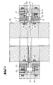
- the illustrated in Figures 1 and 2 embodiment of the rotary feedthrough according to the invention consists of four essential functional elements, the fixed part 1, the sliding rings 2, 3rd and the rotor or rotating part 4.
- the fixed part 1 of the rotary feedthrough is designed so that it forms an annular circumferential clamp, the other elements at least partially encompasses and holds together.
- the rotor 4 is made in one piece in the embodiment shown and has a in substantially hollow cylindrical shape, wherein on the outside of the cylinder symmetrically in half of the height of an annular projection 7 is provided.
- the hollow cylindrical rotor 4 can be pushed over a hollow shaft, wherein two radially encircling O-ring seals 8, 9 the Seal the rotor against the shaft. If the rotor in addition to its seat on the O-rings 8, 9 To be fixed on the shaft, it can be fixed by gluing or screws.
- fixed Part 1 and rotor 4 have approximately the same axial height or length and are in the same Radial level arranged. They also define the entire axial height of the rotary feedthrough.
- the rotor is in the illustrated embodiment provided with two oppositely disposed flow channels 10, 11 which are symmetrical are arranged in the middle of the annular projection 7. It is understood that only one Can be provided channel or more distributed over the circumference channels, since the space 14th surrounds the approach 7 as a continuous volume annular.
- the O-ring seals 8, 9 arranged in the axial direction on both sides of the flow channels 10, 11.
- the hollow cylinder of the rotor 4 is dimensioned substantially so that its outer diameter is smaller is as the inner diameter of the fixed part 1. Only the annular projection 7 protrudes with its outer diameter in the formed of the fixed part 1 annular clamp into it.
- the fixed part 1 on flow channels 12, 13 which connect the outside of the fixed part 1 with the interior 14 of the clamp formed by the fixed part 1. From the interior 14 of the clamp, the fluid flows through the passageways 10, 11 of the rotor 4 in the shaft or in the reverse direction.
- a respective mechanical seal above or below the passageways 10, 11, 12, 13 is provided.
- the mechanical seals consist essentially of two mutually running or sliding sliding surfaces 15, 16 and 17, 18.
- an L-shaped seal ring 2 is arranged, which sits with little play between the fixed 1 and the rotating part 4.
- One of the limbs of the L-shaped sliding ring 2 extends radially outwardly perpendicular to the axis of rotation.
- the sliding ring 2 has on the underside of its axis perpendicular to the axis of rotation an annular peripheral projection 30, the flat bottom surface 15 forms the first sealing surface of the mechanical seal.
- the sealing surface 15 of the sliding ring 2 slides on a second sliding surface 16, which is formed by one of the cover surfaces of the annular projection 7 of the rotor 4.
- the second mechanical seal below the flow channels 10, 11, 12, 13 has identical features as the first mechanical seal, but it is mirrored about the axis of the lead-through openings 10, 11, 12, 13.
- the sliding sealing surfaces 15, 16 and 17, 18 can act sealingly, the sliding rings 2, 3 of distributed over the circumference of the seals springs 19, 20 which bear against the fixed part 1 against the sealing surfaces 16, 18 of the annular projection 7 of the rotor 4 is pressed.
- the second sides of the L-shaped seal rings 2, 3 are sealed by means of annular sealing rings 21, 22 against the fixed part.
- the sealing rings 21, 22 are arranged on the legs parallel to the axis of rotation of the L-shaped seal rings 2, 3.
- the sealing rings 21, 22 have a substantially U-shaped cross-section, so that the slide rings 2, 3 can be easily moved along the sealing rings 21, 22.
- 1 pins 23, 24 are provided on the fixed part, which protrude from the upper and the lower leg of the fixed part 1 in the interior 14 and through the sliding rings. 2 , 3 pass through, so that they can no longer turn against the fixed part 1.
- the slip rings 2, 3 are made of a technical ceramic. These ceramics show good sliding properties while they are high-strength and low-abrasion.
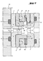
- the L-shaped configuration of the slip rings 2, 3 and the fact that their perpendicular to the axis of rotation Leg flanked both on the top 27 and on the bottom 28 of the fluid allow hydrostatic compensation of the slip rings 2, 3.
- the function of the hydrostatic Compensation can be understood particularly easily with reference to FIG.
- the radial outer end 25 of the axis perpendicular to the axis of rotation of the L-shaped sliding ring 3 has a sufficient distance from the stationary part 1, so that a channel 26 is formed through the fluid from the annular chamber 24 on the top side 27 of the axis of rotation perpendicular Schenkel can flow.
- the pressure of the fluid is constant and on all sides of the sliding ring 3 same size.
- the force in addition to the force of the springs 20 on the surface 32 of the top 27 of the axis perpendicular to the axis of rotation acts equal to the product of the pressure and the size of the upper surface 32.
- On the underside 28 of the vertical axis to the axis of rotation also attacks a hydrostatic force.
- the surface of the bottom 28 is made up of two sections together: from the surface 29 of the leg between the radially outer end 25 and the beginning of the annular projection 30 and from the sealing surface 15 of the annular projection 30.
- the force acting on the surface 29 is again equal to the product of the pressure of the Fluid and the size of the surface 29.
- the force acting on the surface is then calculated as the integral of the Pressure over the area. Since the sealing surface 15 in cooperation with the sealing surface 16 of the rotor prevents leakage of the fluid into the region 31 located behind the annular projection 30, There no hydrostatic force acts on the leg. The total on the bottom 28 of the Schenkel's acting force is equal to the sum of the two contributions. Is the sum of the surface 29 and the sealing surface 15 equal to the upper surface 27 of the leg, so acts due to Pressure decrease along the sealing surface 15 effectively a force from the top of the leg. The position the sealing surface is now chosen so that the acting from below and from above on the leg Just picking up forces. This condition is called hydrostatic compensation. Also, the second seal ring 3 is hydrostatically compensated in the embodiment shown.
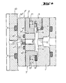
- Figure 3 shows a further embodiment of the invention in which the leakage spaces 31 ', 33', 34 'outside the mechanical seals 15 ', 16' and 17 ', 18' additionally with annular leakage seals 35 ', 36' are sealed from the environment 37 'of the rotary feedthrough. So that can be unavoidable by the mechanical seals (15 ', 16' and 17 ', 18') leaking fluid not in the area (37 ') outside the rotary union.
- Figure 4 shows an alternative embodiment of the embodiment shown in Figures 1 and 2
- the rotary feedthrough in which the rotor 4 "is designed in two parts, consists of a hollow cylindrical core 38 "and halfway up the core 28" pushed ring 39 “ together, so that the two parts 38 “and 39” of the rotor 4 "together in approximately the same outer Have shape as the one-piece rotor 4 of Figures 1 and 2.
- the deferred ring 39 " has a clearance to the core 38 "and the transition between the two elements 38 ", 39” is sealed with the help of two O-rings 40 "and 41” against the environment.
- the deferred Ring 39 has flow holes for the fluid which are aligned with the bores of the core 38", so that the fluid can flow into the shaft.
- the deferred ring 39 "with the Wave and the core 38 "of the rotor 4" can rotate with the help of two on opposite Side of the rotary feedthrough arranged driver pins 42 "connected to the core 38".
- the annular projection 7 of the one-piece rotor 4 also form the end faces of the deferred Rings 39 "sealing surfaces 16", 18 "rotor 4".
Landscapes
- Engineering & Computer Science (AREA)
- General Engineering & Computer Science (AREA)
- Mechanical Engineering (AREA)
- Joints Allowing Movement (AREA)
- Sealing Devices (AREA)
- Sealing Using Fluids, Sealing Without Contact, And Removal Of Oil (AREA)
- Mechanical Sealing (AREA)
- Branch Pipes, Bends, And The Like (AREA)
- Sowing (AREA)
- Ultra Sonic Daignosis Equipment (AREA)
- Rotary Pumps (AREA)
Abstract
Description
Zweckmäßigerweise erstrecken sich dabei sowohl der (einstückige) Rotor als auch das feststehende Teil der Drehdurchführung axial über die volle Höhe Drehdurchführung, wobei der Rotor radial innerhalb des feststehenden Teil angeordnet ist und ein ringförmiger Ansatz des Rotors radial mit einwärts ragenden U-Schenkeln des feststehenden Teil überlappt und zwischen diesen überlappenden Teilen die Gleitringe angeordnet sind, von denen einer auch einstückig mit dem feststehenden Teil ausgebildet sein könnte
Um eine Abdichtung des Innenraums 14 des feststehenden Elements 1 und der Durchflußkanäle 10,11,12,13 gegen den Außenbereich der Drehdurchführung zu erreichen, ist je eine Gleitringdichtung oberhalb bzw. unterhalb der Durchlaßkanäle 10, 11, 12, 13 vorgesehen. Die Gleitringdichtungen bestehen im wesentlichen aus jeweils zwei aufeinander ablaufenden bzw. gleitenden Gleitflächen 15, 16 bzw. 17, 18. Betrachtet man zunächst nur die obere Gleitringdichtung, so sieht man, daß zwischen dem feststehenden Teil 1 und dem Rotor 4 ein L-förmiger Gleitring 2 angeordnet ist, der mit geringem Spiel zwischen dem feststehenden 1 und dem drehenden Teil 4 sitzt. Einer der Schenkel des L-förmigen Gleitrings 2 erstreckt senkrecht zur Drehachse radial nach außen. Der Gleitring 2 weist an der Unterseite seines zur Drehachse senkrechten Schenkels einen ringförmig umlaufenden Ansatz 30 auf, dessen ebene untere Fläche 15 die erste Dichtfläche der Gleitringdichtung bildet. Die Dichtfläche 15 des Gleitrings 2 gleitet auf einer zweiten Gleitfläche 16, die von einer der Deckelflächen des ringförmigen Ansatzes 7 des Rotors 4 gebildet wird. Die zweite Gleitringdichtung unterhalb der Durchflußkanäle 10, 11, 12, 13 weist identische Merkmale wie die erste Gleitringdichtung auf, jedoch ist sie um die Achse der Durchführungsöffnungen 10, 11, 12, 13 gespiegelt. Damit die aufeinander gleitenden Dichtflächen 15, 16 bzw. 17, 18 dichtend wirken können, werden die Gleitringe 2, 3 von über den Umfang der Dichtungen verteilten Federn 19, 20, die sich gegen das feststehende Teil 1 abstützen gegen die Dichtflächen 16, 18 des ringförmigen Ansatzes 7 des Rotors 4 gedrückt. Die zweiten Seiten der L-förmigen Gleitringe 2, 3 sind mit Hilfe von ringförmigen Dichtringen 21, 22 gegen das feststehende Teil gedichtet. Dabei sind die Dichtringe 21, 22 an den zur Drehachse parallelen Schenkeln der L-förmigen Gleitringe 2, 3 angeordnet. Die Dichtringe 21, 22 weisen einen im wesentlichen U-förmigen Querschnitt auf, so daß sich die Gleitringe 2, 3 entlang der Dichtringe 21, 22 leicht verschieben lassen. Um ein Mitdrehen der Gleitringe 2, 3 mit dem Rotor 4 zu verhindern, sind an dem feststehenden Teil 1 Stifte 23, 24 vorgesehen, die von dem oberen bzw. dem unteren Schenkel des feststehenden Teils 1 in den Innenraum 14 hineinragen und durch die Gleitringe 2, 3 durchgreifen, so daß sich diese nicht mehr gegen das feststehende Teil 1 verdrehen lassen.
- 1
- feststehender Teil
- 2
- Gleitring
- 3
- Gleitring
- 4
- Rotor
- 5
- Ring
- 6
- O-Ring
- 7
- ringförmiger Ansatz
- 8
- O-Ringdichtung
- 9
- O-Ringdichtung
- 10
- Durchflußkanal
- 11
- Durchflußkanal
- 12
- Durchlaßkanal
- 13
- Durchlaßkanal
- 14
- Innenraum
- 15
- Gleitfläche
- 16
- Gleitfläche
- 17
- Gleitfläche
- 18
- Gleitfläche
- 19
- Feder
- 20
- Feder
- 21
- Dichtring
- 22
- Dichtring
- 23
- Stift
- 24
- Stift
- 25
- außenliegendes Ende
- 26
- Kanal 26
- 27
- Oberseite
- 28
- Unterseite
- 29
- Fläche
- 30
- ringförmiger Ansatz
- 31
- Bereich hinter dem ringförmigen Ansatz
- 32
- Fläche der Oberseite 27
- 33
- Bereich außerhalb der Gleitringdichtung
- 34
- Bereich außerhalb der Gleitringdichtung
- 35'
- Reibdichtung
- 36'
- Reibdichtung
- 37'
- Umgebung der Drehdurchführung
- 38"
- Kern des zweiteiligen Rotors
- 39"
- aufgeschobener Ring
- 40"
- O-Ring-Dichtung
- 41"
- O-Ring-Dichtung
- 42"
- Mitnehmerstift
Claims (15)
- Radiale Drehdurchführung mit mindestens einem Rotor (4) und mindestens einem feststehenden Teil (1), wobei der mindestens eine Rotor (4) mindestens zwei Dichtflächen aufweist und wobei zwischen dem feststehenden Teil und dem Rotor zwei Gleitringe (2, 3) mit insgesamt mindestens zwei Dichtflächen angeordnet sind, wobei die Dichtflächen (15, 17) der Gleitringe (2, 3) mit den Rotordichtflächen (16, 18) zusammenwirken, und mit mindestens einem radialen Zufuhrdurchgang zwischen den Paaren (15, 16 : 17, 18) zusammenwirkender Dichtflächen dadurch gekennzeichnet, daß die Normalen auf die Dichtflächen des Rotors (4) axial voneinander weg weisen, wobei die Normalen auf die Dichtflächen der Gleitringe (2, 3) axial aufeinander zu gerichtet sind.
- Radiale Drehdurchführung nach Anspruch 1, dadurch gekennzeichnet, daß der Rotor (4) einstückig ausgeführt ist.
- Radiale Drehdurchführung nach Anspruch 1 oder 2, dadurch gekennzeichnet, daß der Rotor (4) einen ringförmigen Ansatz (7) aufweist, dessen Stirnseiten oder Teile davon die Dichtflächen bilden bzw. tragen.
- Radiale Drehdurchführung nach einem der Ansprüche 1 bis 3, dadurch gekennzeichnet, daß das feststehende Teil (1) den Querschnitt eines U-Profils hat und eine ringförmig umlaufende Klammer bildet, wobei die Schenkel des U-Profils axial von außen die Gleitringe (2, 3) und den Rotor (4) oder Teile davon umgreifen.
- Radiale Drehdurchführung nach einem der Ansprüche 1 bis 4, dadurch gekennzeichnet, daß das feststehende Teil (1) aus einem Ring mit L-Profil-Querschnitt und einem daran befestigten Ring (5) besteht, welcher das L-Profil zu einem U-Profil ergänzt.
- Radiale Drehdurchführung nach einem der Ansprüche 1 bis 5, dadurch gekennzeichnet, daß die Gleitringe (2, 3) zwischen den Schenkeln des U-förmigen feststehenden Teils (1) und dem ringförmig umlaufenden Ansatz (7) des Rotors (4) angeordnet sind.
- Radiale Drehdurchführung nach einem der Ansprüche 1 bis 6, dadurch gekennzeichnet, daß die Gleitringdichtungen hydrostatisch kompensiert sind.
- Radiale Drehdurchführung nach Anspruch 7, dadurch gekennzeichnet, daß die Gleitringdichtungen zwischen 90 % und 100 %, vorzugsweise zu etwa 95 %, hydrostatisch kompensiert sind.
- Radiale Drehdurchführung nach einem der Ansprüche 1 bis 8, dadurch geKennzeicnnet, daß sie eine axiale Höhe von weniger als 40 mm, vorzugsweise weniger als 20 mm und besonders bevorzugt von 18 mm aufweist.
- Radiale Drehdurchführung nach einem der Ansprüche 1 bis 9, dadurch gekennzeichnet, daß das Verhältnis der Nennweite (Durchmesser der Welle) zur axialen Höhe der Drehdurchführung größer als 1, vorzugsweise größer als 1,5 und besonders bevorzugt größer als 2 ist.
- Radiale Drehdurchführung nach einem der Ansprüche 1 bis 10, dadurch gekennzeichnet, daß das maximale Verhältnis zwischen der radialen Dicke der Drehdurchführung und ihrer Nennweite kleiner als 1/3, vorzugsweise kleiner als 1/4 und besonders bevorzugt kleiner als 1/6 ist.
- Radiale Drehdurchführung nach einem der Ansprüche 1 bis 11, dadurch gekennzeichnet, daß die Gleitringe (2, 3) aus einer technischen Keramik oder Hartmetall hergestellt sind.
- Radiale Drehdurchführung nach einem der Ansprüche 1 bis 12, dadurch gekennzeichnet, daß die außerhalb der Gleitringdichtungen (15', 16' bzw. 17', 18') liegenden Leckräume (31', 33', 34') der Drehdurchführung mit ringförmigen Leckraumdichtungen (35', 36') gegen die Umgebung (37') abgedichtet sind.
- Radiale Drehdurchführung nach einem der Ansprüche 1 bis 13, dadurch gekennzeichnet, daß der Rotor (4") mehrteilig ausgeführt ist und mindestens einen Kern (38") und mindestens einen aufgeschobenen Ring (39") aufweist, wobei die Stirnseiten des aufgeschobenen Rings (39") oder Teile davon die Dichtflächen bilden bzw. tragen.
- Radiale Drehdurchführung nach einem der Ansprüche 1 bis 14, dadurch gekennzeichnet, daß der mindestens eine aufgeschobene Ring (39") mit mindestens einem Mitnehmerstift 42" mit dem mindestens einen Kern 38" verbunden ist.
Applications Claiming Priority (2)
| Application Number | Priority Date | Filing Date | Title |
|---|---|---|---|
| DE10349968 | 2003-10-24 | ||
| DE10349968A DE10349968A1 (de) | 2003-10-24 | 2003-10-24 | Radiale Drehdurchführung |
Publications (2)
| Publication Number | Publication Date |
|---|---|
| EP1526316A1 true EP1526316A1 (de) | 2005-04-27 |
| EP1526316B1 EP1526316B1 (de) | 2007-01-03 |
Family
ID=34384485
Family Applications (1)
| Application Number | Title | Priority Date | Filing Date |
|---|---|---|---|
| EP04105011A Expired - Lifetime EP1526316B1 (de) | 2003-10-24 | 2004-10-13 | Radiale Drehdurchführung |
Country Status (9)
| Country | Link |
|---|---|
| US (1) | US7407198B2 (de) |
| EP (1) | EP1526316B1 (de) |
| JP (1) | JP4917256B2 (de) |
| KR (1) | KR101097654B1 (de) |
| CN (1) | CN100398897C (de) |
| AT (1) | ATE350613T1 (de) |
| DE (2) | DE10349968A1 (de) |
| ES (1) | ES2281756T3 (de) |
| TW (1) | TWI284724B (de) |
Cited By (3)
| Publication number | Priority date | Publication date | Assignee | Title |
|---|---|---|---|---|
| WO2007014666A3 (de) * | 2005-07-29 | 2007-05-18 | Wilo Ag | Gleitringdichtung |
| WO2009133115A1 (de) * | 2008-05-02 | 2009-11-05 | GAT Gesellschaft für Antriebstechnik mbH | Hochleistungsdrehdurchführung |
| DE102012024557A1 (de) * | 2012-12-15 | 2014-06-18 | Lubova AG | Drehgelenk für Hochdruckvorrichtungen für die Verbindung eines nicht-drehenden Teils mit einem drehenden Teil |
Families Citing this family (19)
| Publication number | Priority date | Publication date | Assignee | Title |
|---|---|---|---|---|
| DE102007032889A1 (de) | 2007-07-14 | 2009-01-15 | Mtu Aero Engines Gmbh | Dichtungsvorrichtung für eine Kühlmittelzufuhr an einer rotierenden Spindel sowie Werkkzeugmaschine mit einer derartigen Dichtungsvorrichtung |
| DE102007049932A1 (de) * | 2007-10-18 | 2009-04-23 | Agco Gmbh | Anschlusselement für ein fluidführendes verschwenkbares Bauteil |
| JP2010270173A (ja) * | 2009-05-19 | 2010-12-02 | Nakanishi Metal Works Co Ltd | アクリル系ゴム組成物及びシール材 |
| TWI426197B (zh) * | 2010-05-13 | 2014-02-11 | Hon Hai Prec Ind Co Ltd | 旋轉接頭及採用該旋轉接頭之旋轉工作台 |
| JP5889330B2 (ja) * | 2010-12-21 | 2016-03-22 | ビエロマティーク ロイツェ ゲゼルシャフト ミット ベシュレンクテルハフツング ウント カンパニー コマンディートゲゼルシャフトbielomatik Leuze GmbH+ Co. KG | 回転式フィードスルー |
| DE102012101814A1 (de) | 2012-03-05 | 2013-09-05 | GAT Gesellschaft für Antriebstechnik mbH | Drehdurchführung mit Wellenlager |
| DE102012101815A1 (de) | 2012-03-05 | 2013-09-05 | GAT Gesellschaft für Antriebstechnik mbH | Drehdurchführung |
| DE102012006901B3 (de) * | 2012-04-05 | 2013-10-10 | Ludwig Volk | Drehdurchführung |
| US20140028016A1 (en) * | 2012-07-30 | 2014-01-30 | Dana Heavy Vehicle Systems Group, Llc | Rotary union for use with a fluid conduit |
| US9790863B2 (en) * | 2013-04-05 | 2017-10-17 | Honeywell International Inc. | Fluid transfer seal assemblies, fluid transfer systems, and methods for transferring process fluid between stationary and rotating components using the same |
| GB2513183B (en) * | 2013-04-19 | 2019-11-13 | Welleng Science & Tech Ltd | Rotary coupling |
| CN104279386B (zh) * | 2013-07-12 | 2017-05-03 | 山东飞越机械有限公司 | 活塞平衡补偿型高速高压旋转接头 |
| DE102015110988A1 (de) | 2015-07-07 | 2017-01-12 | GAT Gesellschaft für Antriebstechnik mbH | Leckreduzierte Drehdurchführung |
| CN107701112B (zh) * | 2017-09-24 | 2024-03-01 | 深圳市阿特拉能源技术有限公司 | 一种用于地质钻探的高效pdc钻头 |
| DE102018208574A1 (de) * | 2018-05-30 | 2019-12-05 | KSB SE & Co. KGaA | Wellendichtungsanordnung |
| US20200217437A1 (en) * | 2019-01-07 | 2020-07-09 | Deublin Company | Rotary joint |
| CN111594679A (zh) * | 2020-06-19 | 2020-08-28 | 江苏贝特管件有限公司 | 旋转补偿器之端面密封结构及旋转补偿器 |
| CN114183079A (zh) * | 2021-11-15 | 2022-03-15 | 河南黄河旋风股份有限公司 | 具备加水排渣功能的钻筒 |
| CN114135234B (zh) * | 2021-12-13 | 2022-08-16 | 河南黄河旋风股份有限公司 | 自适应收放水管的钻进系统 |
Citations (7)
| Publication number | Priority date | Publication date | Assignee | Title |
|---|---|---|---|---|
| US3503469A (en) * | 1967-06-19 | 1970-03-31 | Licentia Gmbh | Bearing lubricating arrangement |
| US4192559A (en) * | 1978-04-28 | 1980-03-11 | Koppers Company, Inc. | Rotary union |
| US4408766A (en) * | 1982-11-29 | 1983-10-11 | Longyear Australia Pty. Ltd. | Rotary seal apparatus with dual self-centering annular face seals |
| US4635969A (en) * | 1985-05-31 | 1987-01-13 | The Johnson Corporation | Rotary joint with balanced seals |
| WO1988002663A1 (en) * | 1986-10-17 | 1988-04-21 | Alfa-Laval Separation Ab | Centrifugal separator |
| DE3927775A1 (de) * | 1988-08-27 | 1990-03-01 | Zahnradfabrik Friedrichshafen | Oelzufuehreinrichtung |
| JPH09196265A (ja) * | 1996-01-19 | 1997-07-29 | Ritsukusu Kk | ロータリジョイント |
Family Cites Families (20)
| Publication number | Priority date | Publication date | Assignee | Title |
|---|---|---|---|---|
| DE1093149B (de) * | 1957-01-04 | 1960-11-17 | Chantiers De Bretagne Anciens | Dichtungsvorrichtung fuer die seitliche Zuleitung eines unter Druck stehenden Mediums in das Innere eines umlaufenden Hohlkoerpers |
| FR1383037A (fr) * | 1963-10-29 | 1964-12-24 | Hispano Suiza Sa | Perfectionnements apportés aux articulations à canaux multiples, notamment à celles pour circuits hydrauliques |
| GB1208793A (en) * | 1967-04-20 | 1970-10-14 | Stromag Maschf | An assembly for use in feeding pressure fluid through a stationary member to a rotary member |
| NL168770C (nl) * | 1976-04-13 | 1982-05-17 | Ihc Holland Nv | Draaibare koppeling voor twee of meer leidingen voor een overslagboei. |
| FR2551832B1 (fr) * | 1983-09-09 | 1985-11-29 | Pinay Jack | Perfectionnements apportes aux raccords tournants |
| DE3806931C2 (de) * | 1987-03-31 | 1993-10-28 | Glyco Antriebstechnik Gmbh | Drehdurchführung zur Übertragung von unter Druck stehenden Medien von einem stehenden in ein rotierendes Maschinenteil |
| GB2205621B (en) * | 1987-04-28 | 1990-11-21 | Glyco Antriebstechnik Gmbh | Hydrostatic rotary connector |
| US5052720A (en) * | 1988-08-18 | 1991-10-01 | Tokyo Sharyo Seizo Kabushiki Kaisha | Swivel joint for high pressure fluid |
| DE4133262A1 (de) * | 1991-10-08 | 1993-04-15 | Siegfried Gulde | Einrichtung zur uebertragung eines mediums |
| NO177780C (no) * | 1993-07-06 | 1995-11-22 | Statoil As | Svivelinnretning for fluidumoverföring |
| NO177779C (no) * | 1993-07-06 | 1995-11-22 | Statoil As | Tetningsanordning for en svivel |
| US5702130A (en) * | 1995-06-12 | 1997-12-30 | Framo Engineering As | Fluid flow connector |
| GB2306588B (en) * | 1995-11-01 | 1999-06-30 | Framo Eng As | Sealing arrangement |
| DE19621020C2 (de) * | 1996-05-24 | 2002-02-07 | Gat Gmbh | Drehdurchführung für hohe Drücke und hohe Relativgeschwindigkeiten |
| GB2321508A (en) * | 1997-01-22 | 1998-07-29 | Single Buoy Moorings | Sealing arrangement in a swivel joint |
| JPH11336970A (ja) | 1998-05-21 | 1999-12-07 | Nippon Pillar Packing Co Ltd | 回転継手装置 |
| DE19932355B4 (de) * | 1999-07-10 | 2010-07-15 | GAT Gesellschaft für Antriebstechnik mbH | Drehdurchführung für wechselnde Medien |
| JP3560144B2 (ja) * | 2000-06-19 | 2004-09-02 | 日本ピラー工業株式会社 | 多流路形ロータリジョイント |
| JP3555936B2 (ja) * | 2000-07-03 | 2004-08-18 | 日本ピラー工業株式会社 | 多流路形ロータリジョイント |
| JP3580774B2 (ja) * | 2000-12-05 | 2004-10-27 | 日本ピラー工業株式会社 | 多流路形ロータリジョイント |
-
2003
- 2003-10-24 DE DE10349968A patent/DE10349968A1/de not_active Withdrawn
-
2004
- 2004-10-13 ES ES04105011T patent/ES2281756T3/es not_active Expired - Lifetime
- 2004-10-13 AT AT04105011T patent/ATE350613T1/de not_active IP Right Cessation
- 2004-10-13 EP EP04105011A patent/EP1526316B1/de not_active Expired - Lifetime
- 2004-10-13 DE DE502004002518T patent/DE502004002518D1/de not_active Expired - Lifetime
- 2004-10-15 US US10/966,557 patent/US7407198B2/en not_active Expired - Lifetime
- 2004-10-22 JP JP2004308253A patent/JP4917256B2/ja not_active Expired - Fee Related
- 2004-10-22 TW TW093132215A patent/TWI284724B/zh not_active IP Right Cessation
- 2004-10-22 KR KR1020040084898A patent/KR101097654B1/ko not_active Expired - Lifetime
- 2004-10-25 CN CNB2004100841639A patent/CN100398897C/zh not_active Expired - Fee Related
Patent Citations (7)
| Publication number | Priority date | Publication date | Assignee | Title |
|---|---|---|---|---|
| US3503469A (en) * | 1967-06-19 | 1970-03-31 | Licentia Gmbh | Bearing lubricating arrangement |
| US4192559A (en) * | 1978-04-28 | 1980-03-11 | Koppers Company, Inc. | Rotary union |
| US4408766A (en) * | 1982-11-29 | 1983-10-11 | Longyear Australia Pty. Ltd. | Rotary seal apparatus with dual self-centering annular face seals |
| US4635969A (en) * | 1985-05-31 | 1987-01-13 | The Johnson Corporation | Rotary joint with balanced seals |
| WO1988002663A1 (en) * | 1986-10-17 | 1988-04-21 | Alfa-Laval Separation Ab | Centrifugal separator |
| DE3927775A1 (de) * | 1988-08-27 | 1990-03-01 | Zahnradfabrik Friedrichshafen | Oelzufuehreinrichtung |
| JPH09196265A (ja) * | 1996-01-19 | 1997-07-29 | Ritsukusu Kk | ロータリジョイント |
Non-Patent Citations (1)
| Title |
|---|
| PATENT ABSTRACTS OF JAPAN vol. 1997, no. 11 28 November 1997 (1997-11-28) * |
Cited By (3)
| Publication number | Priority date | Publication date | Assignee | Title |
|---|---|---|---|---|
| WO2007014666A3 (de) * | 2005-07-29 | 2007-05-18 | Wilo Ag | Gleitringdichtung |
| WO2009133115A1 (de) * | 2008-05-02 | 2009-11-05 | GAT Gesellschaft für Antriebstechnik mbH | Hochleistungsdrehdurchführung |
| DE102012024557A1 (de) * | 2012-12-15 | 2014-06-18 | Lubova AG | Drehgelenk für Hochdruckvorrichtungen für die Verbindung eines nicht-drehenden Teils mit einem drehenden Teil |
Also Published As
| Publication number | Publication date |
|---|---|
| CN100398897C (zh) | 2008-07-02 |
| ATE350613T1 (de) | 2007-01-15 |
| US20050111770A1 (en) | 2005-05-26 |
| EP1526316B1 (de) | 2007-01-03 |
| DE10349968A1 (de) | 2005-05-25 |
| US7407198B2 (en) | 2008-08-05 |
| JP4917256B2 (ja) | 2012-04-18 |
| KR20050039660A (ko) | 2005-04-29 |
| CN1626865A (zh) | 2005-06-15 |
| TWI284724B (en) | 2007-08-01 |
| KR101097654B1 (ko) | 2011-12-22 |
| TW200523493A (en) | 2005-07-16 |
| JP2005127518A (ja) | 2005-05-19 |
| DE502004002518D1 (de) | 2007-02-15 |
| ES2281756T3 (es) | 2007-10-01 |
Similar Documents
| Publication | Publication Date | Title |
|---|---|---|
| EP1526316B1 (de) | Radiale Drehdurchführung | |
| DE19621020C2 (de) | Drehdurchführung für hohe Drücke und hohe Relativgeschwindigkeiten | |
| DE60101537T2 (de) | Nockenmechanismus mit Kreuzrollenlager | |
| DE102009054794B4 (de) | Radiale Drehdurchführung und Buchse hierfür | |
| EP2039975A2 (de) | Radiale Drehdurchführung | |
| EP2994657B1 (de) | Fettgeschmiertes schrägkugellager | |
| EP1069362A2 (de) | Drehdurchführung für wechselnde Medien | |
| DE19614385A1 (de) | Dichtung für einen Ringkolben einer hydraulischen Kupplungs-Ausrückvorrichtung | |
| DE69310494T2 (de) | Hochgeschwindigkeitsdrehverbindung | |
| DE3316332C2 (de) | ||
| DE102015215296A1 (de) | Lageranordnung und Lagerring zum drehbeweglichen Lagern eines ersten Bauteils gegenüber einem zweiten Bauteil sowie Schraubenkompressor mit der Lageranordnung oder dem Lagerring | |
| EP1639288B1 (de) | Drehdurchführung | |
| DE102008064456B4 (de) | Servolenkungsvorrichtung | |
| EP4390186A1 (de) | Dichtungssystem für unterwasserturbine | |
| DE19815134B4 (de) | Spindelkopf für Werkzeugmaschinen | |
| DE102020212070A1 (de) | Gleitringdichtungsgerät und anordnung eines gleitringdichtungsgeräts in einer achsabstützung | |
| DE10332010B4 (de) | Drehdurchführung | |
| EP1446604B1 (de) | Anschlussblock für hydraulik-versorgungsleitungen der hydrostatikanlage eines ölfilmlagers | |
| EP0812397B1 (de) | Reibschlüssige drehverbindung | |
| DE10238415A1 (de) | Gleitlager für eine Welle eines Abgasturboladers | |
| DE3612495A1 (de) | Drucklager/dichtungs-anordnung | |
| DE10040211C2 (de) | Vorrichtung zur Abdichtung von Antriebswellen | |
| DE2818664C2 (de) | Dichtungsanordnung für eine Wellendurchführung | |
| DE202008002709U1 (de) | Lageranordnung | |
| DE8136101U1 (de) | "kupplung zur reibschluessigen drehverbindung von maschinenteilen, wie z.b. nabe und welle" |
Legal Events
| Date | Code | Title | Description |
|---|---|---|---|
| PUAI | Public reference made under article 153(3) epc to a published international application that has entered the european phase |
Free format text: ORIGINAL CODE: 0009012 |
|
| AK | Designated contracting states |
Kind code of ref document: A1 Designated state(s): AT BE BG CH CY CZ DE DK EE ES FI FR GB GR HU IE IT LI LU MC NL PL PT RO SE SI SK TR |
|
| AX | Request for extension of the european patent |
Extension state: AL HR LT LV MK |
|
| 17P | Request for examination filed |
Effective date: 20050928 |
|
| AKX | Designation fees paid |
Designated state(s): AT BE BG CH CY CZ DE DK EE ES FI FR GB GR HU IE IT LI LU MC NL PL PT RO SE SI SK TR |
|
| GRAP | Despatch of communication of intention to grant a patent |
Free format text: ORIGINAL CODE: EPIDOSNIGR1 |
|
| GRAS | Grant fee paid |
Free format text: ORIGINAL CODE: EPIDOSNIGR3 |
|
| GRAA | (expected) grant |
Free format text: ORIGINAL CODE: 0009210 |
|
| AK | Designated contracting states |
Kind code of ref document: B1 Designated state(s): AT BE BG CH CY CZ DE DK EE ES FI FR GB GR HU IE IT LI LU MC NL PL PT RO SE SI SK TR |
|
| PG25 | Lapsed in a contracting state [announced via postgrant information from national office to epo] |
Ref country code: PL Free format text: LAPSE BECAUSE OF FAILURE TO SUBMIT A TRANSLATION OF THE DESCRIPTION OR TO PAY THE FEE WITHIN THE PRESCRIBED TIME-LIMIT Effective date: 20070103 Ref country code: NL Free format text: LAPSE BECAUSE OF FAILURE TO SUBMIT A TRANSLATION OF THE DESCRIPTION OR TO PAY THE FEE WITHIN THE PRESCRIBED TIME-LIMIT Effective date: 20070103 Ref country code: IE Free format text: LAPSE BECAUSE OF FAILURE TO SUBMIT A TRANSLATION OF THE DESCRIPTION OR TO PAY THE FEE WITHIN THE PRESCRIBED TIME-LIMIT Effective date: 20070103 Ref country code: FI Free format text: LAPSE BECAUSE OF FAILURE TO SUBMIT A TRANSLATION OF THE DESCRIPTION OR TO PAY THE FEE WITHIN THE PRESCRIBED TIME-LIMIT Effective date: 20070103 Ref country code: SI Free format text: LAPSE BECAUSE OF FAILURE TO SUBMIT A TRANSLATION OF THE DESCRIPTION OR TO PAY THE FEE WITHIN THE PRESCRIBED TIME-LIMIT Effective date: 20070103 Ref country code: DK Free format text: LAPSE BECAUSE OF FAILURE TO SUBMIT A TRANSLATION OF THE DESCRIPTION OR TO PAY THE FEE WITHIN THE PRESCRIBED TIME-LIMIT Effective date: 20070103 |
|
| REG | Reference to a national code |
Ref country code: GB Ref legal event code: FG4D Free format text: NOT ENGLISH |
|
| REF | Corresponds to: |
Ref document number: 502004002518 Country of ref document: DE Date of ref document: 20070215 Kind code of ref document: P |
|
| REG | Reference to a national code |
Ref country code: IE Ref legal event code: FG4D Free format text: LANGUAGE OF EP DOCUMENT: GERMAN |
|
| PG25 | Lapsed in a contracting state [announced via postgrant information from national office to epo] |
Ref country code: SE Free format text: LAPSE BECAUSE OF FAILURE TO SUBMIT A TRANSLATION OF THE DESCRIPTION OR TO PAY THE FEE WITHIN THE PRESCRIBED TIME-LIMIT Effective date: 20070403 |
|
| PG25 | Lapsed in a contracting state [announced via postgrant information from national office to epo] |
Ref country code: BG Free format text: LAPSE BECAUSE OF FAILURE TO SUBMIT A TRANSLATION OF THE DESCRIPTION OR TO PAY THE FEE WITHIN THE PRESCRIBED TIME-LIMIT Effective date: 20070404 |
|
| REG | Reference to a national code |
Ref country code: CH Ref legal event code: NV Representative=s name: AMMANN PATENTANWAELTE AG BERN |
|
| PG25 | Lapsed in a contracting state [announced via postgrant information from national office to epo] |
Ref country code: PT Free format text: LAPSE BECAUSE OF FAILURE TO SUBMIT A TRANSLATION OF THE DESCRIPTION OR TO PAY THE FEE WITHIN THE PRESCRIBED TIME-LIMIT Effective date: 20070604 |
|
| NLV1 | Nl: lapsed or annulled due to failure to fulfill the requirements of art. 29p and 29m of the patents act | ||
| ET | Fr: translation filed | ||
| GBV | Gb: ep patent (uk) treated as always having been void in accordance with gb section 77(7)/1977 [no translation filed] |
Effective date: 20070103 |
|
| REG | Reference to a national code |
Ref country code: IE Ref legal event code: FD4D |
|
| REG | Reference to a national code |
Ref country code: ES Ref legal event code: FG2A Ref document number: 2281756 Country of ref document: ES Kind code of ref document: T3 |
|
| PLBE | No opposition filed within time limit |
Free format text: ORIGINAL CODE: 0009261 |
|
| STAA | Information on the status of an ep patent application or granted ep patent |
Free format text: STATUS: NO OPPOSITION FILED WITHIN TIME LIMIT |
|
| PG25 | Lapsed in a contracting state [announced via postgrant information from national office to epo] |
Ref country code: GB Free format text: LAPSE BECAUSE OF FAILURE TO SUBMIT A TRANSLATION OF THE DESCRIPTION OR TO PAY THE FEE WITHIN THE PRESCRIBED TIME-LIMIT Effective date: 20070103 Ref country code: SK Free format text: LAPSE BECAUSE OF FAILURE TO SUBMIT A TRANSLATION OF THE DESCRIPTION OR TO PAY THE FEE WITHIN THE PRESCRIBED TIME-LIMIT Effective date: 20070103 |
|
| 26N | No opposition filed |
Effective date: 20071005 |
|
| PG25 | Lapsed in a contracting state [announced via postgrant information from national office to epo] |
Ref country code: RO Free format text: LAPSE BECAUSE OF FAILURE TO SUBMIT A TRANSLATION OF THE DESCRIPTION OR TO PAY THE FEE WITHIN THE PRESCRIBED TIME-LIMIT Effective date: 20070103 Ref country code: CZ Free format text: LAPSE BECAUSE OF FAILURE TO SUBMIT A TRANSLATION OF THE DESCRIPTION OR TO PAY THE FEE WITHIN THE PRESCRIBED TIME-LIMIT Effective date: 20070103 |
|
| BERE | Be: lapsed |
Owner name: GAT G.- FUR ANTRIEBSTECHNIK MBH Effective date: 20071031 |
|
| PG25 | Lapsed in a contracting state [announced via postgrant information from national office to epo] |
Ref country code: GR Free format text: LAPSE BECAUSE OF FAILURE TO SUBMIT A TRANSLATION OF THE DESCRIPTION OR TO PAY THE FEE WITHIN THE PRESCRIBED TIME-LIMIT Effective date: 20070404 |
|
| PG25 | Lapsed in a contracting state [announced via postgrant information from national office to epo] |
Ref country code: MC Free format text: LAPSE BECAUSE OF NON-PAYMENT OF DUE FEES Effective date: 20071031 |
|
| PG25 | Lapsed in a contracting state [announced via postgrant information from national office to epo] |
Ref country code: BE Free format text: LAPSE BECAUSE OF NON-PAYMENT OF DUE FEES Effective date: 20071031 |
|
| PG25 | Lapsed in a contracting state [announced via postgrant information from national office to epo] |
Ref country code: EE Free format text: LAPSE BECAUSE OF FAILURE TO SUBMIT A TRANSLATION OF THE DESCRIPTION OR TO PAY THE FEE WITHIN THE PRESCRIBED TIME-LIMIT Effective date: 20070103 |
|
| PG25 | Lapsed in a contracting state [announced via postgrant information from national office to epo] |
Ref country code: AT Free format text: LAPSE BECAUSE OF NON-PAYMENT OF DUE FEES Effective date: 20071013 |
|
| PG25 | Lapsed in a contracting state [announced via postgrant information from national office to epo] |
Ref country code: CY Free format text: LAPSE BECAUSE OF FAILURE TO SUBMIT A TRANSLATION OF THE DESCRIPTION OR TO PAY THE FEE WITHIN THE PRESCRIBED TIME-LIMIT Effective date: 20070103 |
|
| PG25 | Lapsed in a contracting state [announced via postgrant information from national office to epo] |
Ref country code: LU Free format text: LAPSE BECAUSE OF NON-PAYMENT OF DUE FEES Effective date: 20071013 |
|
| PG25 | Lapsed in a contracting state [announced via postgrant information from national office to epo] |
Ref country code: TR Free format text: LAPSE BECAUSE OF FAILURE TO SUBMIT A TRANSLATION OF THE DESCRIPTION OR TO PAY THE FEE WITHIN THE PRESCRIBED TIME-LIMIT Effective date: 20070103 Ref country code: HU Free format text: LAPSE BECAUSE OF FAILURE TO SUBMIT A TRANSLATION OF THE DESCRIPTION OR TO PAY THE FEE WITHIN THE PRESCRIBED TIME-LIMIT Effective date: 20070704 |
|
| PGFP | Annual fee paid to national office [announced via postgrant information from national office to epo] |
Ref country code: FR Payment date: 20111118 Year of fee payment: 8 Ref country code: ES Payment date: 20111125 Year of fee payment: 8 |
|
| REG | Reference to a national code |
Ref country code: FR Ref legal event code: ST Effective date: 20130628 |
|
| PG25 | Lapsed in a contracting state [announced via postgrant information from national office to epo] |
Ref country code: FR Free format text: LAPSE BECAUSE OF NON-PAYMENT OF DUE FEES Effective date: 20121031 |
|
| PGFP | Annual fee paid to national office [announced via postgrant information from national office to epo] |
Ref country code: CH Payment date: 20131021 Year of fee payment: 10 |
|
| REG | Reference to a national code |
Ref country code: ES Ref legal event code: FD2A Effective date: 20140411 |
|
| PG25 | Lapsed in a contracting state [announced via postgrant information from national office to epo] |
Ref country code: ES Free format text: LAPSE BECAUSE OF NON-PAYMENT OF DUE FEES Effective date: 20121014 |
|
| REG | Reference to a national code |
Ref country code: CH Ref legal event code: PL |
|
| PG25 | Lapsed in a contracting state [announced via postgrant information from national office to epo] |
Ref country code: CH Free format text: LAPSE BECAUSE OF NON-PAYMENT OF DUE FEES Effective date: 20141031 Ref country code: LI Free format text: LAPSE BECAUSE OF NON-PAYMENT OF DUE FEES Effective date: 20141031 |
|
| PGFP | Annual fee paid to national office [announced via postgrant information from national office to epo] |
Ref country code: IT Payment date: 20161024 Year of fee payment: 13 |
|
| PG25 | Lapsed in a contracting state [announced via postgrant information from national office to epo] |
Ref country code: IT Free format text: LAPSE BECAUSE OF NON-PAYMENT OF DUE FEES Effective date: 20171013 |
|
| REG | Reference to a national code |
Ref country code: DE Ref legal event code: R082 Ref document number: 502004002518 Country of ref document: DE Representative=s name: WITHERS & ROGERS LLP, DE Ref country code: DE Ref legal event code: R081 Ref document number: 502004002518 Country of ref document: DE Owner name: MOOG GAT GMBH, DE Free format text: FORMER OWNER: GAT GESELLSCHAFT FUER ANTRIEBSTECHNIK MBH, 65201 WIESBADEN, DE |
|
| PGFP | Annual fee paid to national office [announced via postgrant information from national office to epo] |
Ref country code: DE Payment date: 20231020 Year of fee payment: 20 |
|
| REG | Reference to a national code |
Ref country code: DE Ref legal event code: R071 Ref document number: 502004002518 Country of ref document: DE |