EP1526316A1 - Radial rotary connection - Google Patents
Radial rotary connection Download PDFInfo
- Publication number
- EP1526316A1 EP1526316A1 EP04105011A EP04105011A EP1526316A1 EP 1526316 A1 EP1526316 A1 EP 1526316A1 EP 04105011 A EP04105011 A EP 04105011A EP 04105011 A EP04105011 A EP 04105011A EP 1526316 A1 EP1526316 A1 EP 1526316A1
- Authority
- EP
- European Patent Office
- Prior art keywords
- rotor
- rotary feedthrough
- sealing surfaces
- radial rotary
- radial
- Prior art date
- Legal status (The legal status is an assumption and is not a legal conclusion. Google has not performed a legal analysis and makes no representation as to the accuracy of the status listed.)
- Granted
Links
- 238000007789 sealing Methods 0.000 claims abstract description 64
- 239000000919 ceramic Substances 0.000 claims description 5
- 239000002184 metal Substances 0.000 claims description 2
- 229910052751 metal Inorganic materials 0.000 claims description 2
- 230000002093 peripheral effect Effects 0.000 claims description 2
- 230000005540 biological transmission Effects 0.000 abstract 1
- 239000012530 fluid Substances 0.000 description 22
- 230000002706 hydrostatic effect Effects 0.000 description 6
- 238000009434 installation Methods 0.000 description 5
- 238000010276 construction Methods 0.000 description 4
- 239000002826 coolant Substances 0.000 description 3
- 230000007423 decrease Effects 0.000 description 2
- 210000003746 feather Anatomy 0.000 description 2
- 238000003754 machining Methods 0.000 description 2
- 238000004519 manufacturing process Methods 0.000 description 2
- 238000009420 retrofitting Methods 0.000 description 2
- 230000007704 transition Effects 0.000 description 2
- 229910000851 Alloy steel Inorganic materials 0.000 description 1
- 229910000906 Bronze Inorganic materials 0.000 description 1
- 238000005299 abrasion Methods 0.000 description 1
- 239000000853 adhesive Substances 0.000 description 1
- 238000004026 adhesive bonding Methods 0.000 description 1
- 230000001070 adhesive effect Effects 0.000 description 1
- 230000006735 deficit Effects 0.000 description 1
- 238000007667 floating Methods 0.000 description 1
- 150000002739 metals Chemical class 0.000 description 1
- 238000000034 method Methods 0.000 description 1
- 238000005457 optimization Methods 0.000 description 1
- 238000005476 soldering Methods 0.000 description 1
- 239000010959 steel Substances 0.000 description 1
- 238000003860 storage Methods 0.000 description 1
- UONOETXJSWQNOL-UHFFFAOYSA-N tungsten carbide Chemical compound [W+]#[C-] UONOETXJSWQNOL-UHFFFAOYSA-N 0.000 description 1
- 238000003466 welding Methods 0.000 description 1
Images

Classifications
-
- F—MECHANICAL ENGINEERING; LIGHTING; HEATING; WEAPONS; BLASTING
- F16—ENGINEERING ELEMENTS AND UNITS; GENERAL MEASURES FOR PRODUCING AND MAINTAINING EFFECTIVE FUNCTIONING OF MACHINES OR INSTALLATIONS; THERMAL INSULATION IN GENERAL
- F16J—PISTONS; CYLINDERS; SEALINGS
- F16J15/00—Sealings
- F16J15/16—Sealings between relatively-moving surfaces
- F16J15/34—Sealings between relatively-moving surfaces with slip-ring pressed against a more or less radial face on one member
- F16J15/3464—Mounting of the seal
- F16J15/348—Pre-assembled seals, e.g. cartridge seals
- F16J15/3484—Tandem seals
-
- B—PERFORMING OPERATIONS; TRANSPORTING
- B65—CONVEYING; PACKING; STORING; HANDLING THIN OR FILAMENTARY MATERIAL
- B65G—TRANSPORT OR STORAGE DEVICES, e.g. CONVEYORS FOR LOADING OR TIPPING, SHOP CONVEYOR SYSTEMS OR PNEUMATIC TUBE CONVEYORS
- B65G33/00—Screw or rotary spiral conveyors
-
- B—PERFORMING OPERATIONS; TRANSPORTING
- B65—CONVEYING; PACKING; STORING; HANDLING THIN OR FILAMENTARY MATERIAL
- B65G—TRANSPORT OR STORAGE DEVICES, e.g. CONVEYORS FOR LOADING OR TIPPING, SHOP CONVEYOR SYSTEMS OR PNEUMATIC TUBE CONVEYORS
- B65G33/00—Screw or rotary spiral conveyors
- B65G33/08—Screw or rotary spiral conveyors for fluent solid materials
-
- F—MECHANICAL ENGINEERING; LIGHTING; HEATING; WEAPONS; BLASTING
- F16—ENGINEERING ELEMENTS AND UNITS; GENERAL MEASURES FOR PRODUCING AND MAINTAINING EFFECTIVE FUNCTIONING OF MACHINES OR INSTALLATIONS; THERMAL INSULATION IN GENERAL
- F16L—PIPES; JOINTS OR FITTINGS FOR PIPES; SUPPORTS FOR PIPES, CABLES OR PROTECTIVE TUBING; MEANS FOR THERMAL INSULATION IN GENERAL
- F16L27/00—Adjustable joints; Joints allowing movement
- F16L27/08—Adjustable joints; Joints allowing movement allowing adjustment or movement only about the axis of one pipe
- F16L27/087—Joints with radial fluid passages
-
- F—MECHANICAL ENGINEERING; LIGHTING; HEATING; WEAPONS; BLASTING
- F16—ENGINEERING ELEMENTS AND UNITS; GENERAL MEASURES FOR PRODUCING AND MAINTAINING EFFECTIVE FUNCTIONING OF MACHINES OR INSTALLATIONS; THERMAL INSULATION IN GENERAL
- F16L—PIPES; JOINTS OR FITTINGS FOR PIPES; SUPPORTS FOR PIPES, CABLES OR PROTECTIVE TUBING; MEANS FOR THERMAL INSULATION IN GENERAL
- F16L41/00—Branching pipes; Joining pipes to walls
Definitions
- the invention relates to a radial rotary feedthrough with at least one rotor and at least a fixed part, wherein the at least one rotor at least two axially spaced Has sealing surfaces and wherein between the fixed part and the rotor two slip rings are arranged with a total of at least two sealing surfaces, wherein the sealing surfaces of the sliding rings interact with the rotor sealing surfaces, and with at least one radial feed passage between the pairs of cooperating sealing surfaces.
- Rotary unions for fluids from a fixed to a rotating machine part are off known in the art.
- the technical problem to be solved by all rotary feedthroughs is to make a tight transition between two mutually rotating parts.
- the rotary feedthroughs known from the prior art are either axial feedthroughs, in which the fluid along the axis of rotation or parallel to it in the rotating machine part is transferred or radial rotary unions.
- Japanese Patent Publication JP 09196265 A shows such a radial rotary feedthrough, in which the fluid in a direction perpendicular to the axis of rotation of the rotating machine part of the fixed Machine part is transferred to the rotating part.
- the turning Part hereinafter also referred to as rotor
- two annular projections provided, the axial sealing surfaces have, the surface normal in the direction of the axis of rotation and the annular order rotate the axis of rotation of the rotor.
- the sealing surfaces of two sliding rings are based from.
- the sliding rings are secured against rotation with the rotor on the fixed part and their sealing surfaces are supported by themselves against a portion of the fixed part Pressed springs against the sealing surfaces of the rotor.
- the supply of the fluid takes place through a channel between the two sliding rings in a direction perpendicular to the axis of rotation of the Rotor. A leakage of the fluid is so with the help of the superimposed sealing surfaces of the Rotor and the two sliding rings and seals between the fixed part and the Prevents sliding rings.
- the rotary feedthrough known from JP 09196265 A has a very complex, voluminous Construction.
- the part carrying the Gleitdicht lake connected to a shaft consists of two axially spaced rotor rings, each associated with a sliding ring.
- the rotor rings must be sealed be fixed on the shaft.
- Each rotor ring is assigned its own sliding ring, which is not with rotated, but axially floating and resiliently biased on the shaft is arranged to regardless of any component and assembly tolerances always a dense edition of its Gleitdicht vin to ensure.
- the fixed part has for storage and support of the slip rings a radially inwardly projecting collar, which is arranged between the sliding rings and Press the sliding rings against the rotor ring via springs. This construction requires a lot Space in both the axial and in the radial direction.
- Radial (and also axial) rotary unions are used, among other things, for internal coolant supply used in machine tools.
- a disadvantage of these rotary joints is however in that they are relatively bulky and require space on a tool spindle. This is particularly disturbing in modern machining centers, which in any case accommodate tool magazines and turrets need.
- the present invention has the object, a radial rotary feedthrough design so that their installation in machining centers and Retrofitting to existing facilities is simplified and not on the low existing Place fails.
- a radial rotary feedthrough is provided with at least a rotor and at least one stationary part, wherein the at least one rotor has at least two sealing surfaces and wherein between the fixed part and the rotor two sliding rings are arranged with a total of at least two sealing surfaces, wherein the sealing surfaces the sliding rings cooperate with the rotor sealing surfaces, and with at least one radial feed passage between the pairs of cooperating sealing surfaces, the normal to the Have sealing surfaces of the rotor axially away from each other, the normal to the sealing surfaces of the Sliding rings are directed axially towards each other.
- the sliding sealing surfaces of the rotor on one and the same component be arranged and a particular advantage in this construction is that they are with a reduced axial height can be provided.
- the axial height i. H. the dimension the rotary feedthrough in a direction parallel to the axis of rotation of the rotor less than 40 mm, preferably less than 20 mm and particularly preferably 18 mm.
- the ratio of the diameter of the shaft to the axial height of Rotary feedthrough greater than 1, preferably greater than 1.5 and more preferably greater than 2 is. This ensures relatively low installation dimensions of the rotary unions even for large Shaft diameter.
- the maximum ratio between the radial thickness of the rotary feedthrough and the diameter of the shaft is less than 1/3, preferably less than 1/5 and especially preferably less than 1/6.
- the radial installation dimension holds even at relatively large Waves within limits.
- the rotor is made in one piece. This saves time and costs in the manufacture and especially in the assembly of the rotor.
- An embodiment of the invention is preferred in which the rotor has an annular projection has, whose end faces or parts thereof form the sealing surfaces. Because both sealing surfaces parts of the annular approach, less space is required than when using one support for each sealing surface.
- the annular approach in the axial direction be carried out relatively thin, since the sealing surfaces on the opposite cover surfaces of the annular approach, so that compensate for the forces exerted on the sealing surfaces forces. This also saves axial height.
- the axial height of the approach must be sufficient to be between the sliding surfaces formed by the end faces of the neck become, still a radial bore or a passage, which also a non-round, narrow Cross-section z. B. can have a long hole to accommodate.
- the rotor is designed in several parts, wherein he has at least one core and at least one deferred ring.
- the End faces of the pushed ring or parts thereof the sealing surfaces are advantageous because it allows easier manufacture and installation of the rotor.
- the deferred Ring preferably forms the annular projection or has the annular projection on which the axial sealing surfaces are arranged.
- the at least one deferred ring over at least a driving pin is connected to the at least one core. So are the rotational movements the core and the deferred ring coupled together.
- the fixed part consists of a ring with L-profile cross-section and a ring attached thereto, which complements the L-profile to a U-profile. So the fixed part can be carried out in one piece up to the ring.
- the ring is attached and completed, the L-profile to a U-profile, which surrounds the seal rings and the rotor or parts thereof.
- the ring has on its outer side a thread by means of which the ring can be screwed into the L-profile. Alternatively, it can be attached to the L-profile with additional screws.
- a welding, soldering or adhesive connection is conceivable.
- both the (one-piece) rotor and the fixed part of the rotary leadthrough extend axially over the full height of the rotary leadthrough, wherein the rotor is arranged radially inside the fixed part and an annular projection of the rotor radially with inwardly projecting U-legs of the fixed part overlapped and between these overlapping parts, the sliding rings are arranged, one of which could also be formed integrally with the fixed part
- the mechanical seals are hydrostatically compensated.
- a slip ring with opposite Equal sized end faces are surrounded by a pressurized fluid.
- the hydrostatic pressure on a sealing surface of a sliding ring, on the opposite Sliding surface of a rotating part expires, increases with the distance from that with fluid filled chamber and is zero at the other end of the slip ring. Therefore, with the same area the upper and lower sides of the sliding ring, the force on the side of the sliding surface less than the force on the opposite side.
- the slip rings are made of a technical ceramic or tungsten carbide.
- Such ceramics or hard metals are high strength and have good sliding properties, while only one subject to low wear.
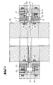
- the illustrated in Figures 1 and 2 embodiment of the rotary feedthrough according to the invention consists of four essential functional elements, the fixed part 1, the sliding rings 2, 3rd and the rotor or rotating part 4.
- the fixed part 1 of the rotary feedthrough is designed so that it forms an annular circumferential clamp, the other elements at least partially encompasses and holds together.
- the rotor 4 is made in one piece in the embodiment shown and has a in substantially hollow cylindrical shape, wherein on the outside of the cylinder symmetrically in half of the height of an annular projection 7 is provided.
- the hollow cylindrical rotor 4 can be pushed over a hollow shaft, wherein two radially encircling O-ring seals 8, 9 the Seal the rotor against the shaft. If the rotor in addition to its seat on the O-rings 8, 9 To be fixed on the shaft, it can be fixed by gluing or screws.
- fixed Part 1 and rotor 4 have approximately the same axial height or length and are in the same Radial level arranged. They also define the entire axial height of the rotary feedthrough.
- the rotor is in the illustrated embodiment provided with two oppositely disposed flow channels 10, 11 which are symmetrical are arranged in the middle of the annular projection 7. It is understood that only one Can be provided channel or more distributed over the circumference channels, since the space 14th surrounds the approach 7 as a continuous volume annular.
- the O-ring seals 8, 9 arranged in the axial direction on both sides of the flow channels 10, 11.
- the hollow cylinder of the rotor 4 is dimensioned substantially so that its outer diameter is smaller is as the inner diameter of the fixed part 1. Only the annular projection 7 protrudes with its outer diameter in the formed of the fixed part 1 annular clamp into it.
- the fixed part 1 on flow channels 12, 13 which connect the outside of the fixed part 1 with the interior 14 of the clamp formed by the fixed part 1. From the interior 14 of the clamp, the fluid flows through the passageways 10, 11 of the rotor 4 in the shaft or in the reverse direction.
- a respective mechanical seal above or below the passageways 10, 11, 12, 13 is provided.
- the mechanical seals consist essentially of two mutually running or sliding sliding surfaces 15, 16 and 17, 18.
- an L-shaped seal ring 2 is arranged, which sits with little play between the fixed 1 and the rotating part 4.
- One of the limbs of the L-shaped sliding ring 2 extends radially outwardly perpendicular to the axis of rotation.
- the sliding ring 2 has on the underside of its axis perpendicular to the axis of rotation an annular peripheral projection 30, the flat bottom surface 15 forms the first sealing surface of the mechanical seal.
- the sealing surface 15 of the sliding ring 2 slides on a second sliding surface 16, which is formed by one of the cover surfaces of the annular projection 7 of the rotor 4.
- the second mechanical seal below the flow channels 10, 11, 12, 13 has identical features as the first mechanical seal, but it is mirrored about the axis of the lead-through openings 10, 11, 12, 13.
- the sliding sealing surfaces 15, 16 and 17, 18 can act sealingly, the sliding rings 2, 3 of distributed over the circumference of the seals springs 19, 20 which bear against the fixed part 1 against the sealing surfaces 16, 18 of the annular projection 7 of the rotor 4 is pressed.
- the second sides of the L-shaped seal rings 2, 3 are sealed by means of annular sealing rings 21, 22 against the fixed part.
- the sealing rings 21, 22 are arranged on the legs parallel to the axis of rotation of the L-shaped seal rings 2, 3.
- the sealing rings 21, 22 have a substantially U-shaped cross-section, so that the slide rings 2, 3 can be easily moved along the sealing rings 21, 22.
- 1 pins 23, 24 are provided on the fixed part, which protrude from the upper and the lower leg of the fixed part 1 in the interior 14 and through the sliding rings. 2 , 3 pass through, so that they can no longer turn against the fixed part 1.
- the slip rings 2, 3 are made of a technical ceramic. These ceramics show good sliding properties while they are high-strength and low-abrasion.
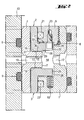
- the L-shaped configuration of the slip rings 2, 3 and the fact that their perpendicular to the axis of rotation Leg flanked both on the top 27 and on the bottom 28 of the fluid allow hydrostatic compensation of the slip rings 2, 3.
- the function of the hydrostatic Compensation can be understood particularly easily with reference to FIG.
- the radial outer end 25 of the axis perpendicular to the axis of rotation of the L-shaped sliding ring 3 has a sufficient distance from the stationary part 1, so that a channel 26 is formed through the fluid from the annular chamber 24 on the top side 27 of the axis of rotation perpendicular Schenkel can flow.
- the pressure of the fluid is constant and on all sides of the sliding ring 3 same size.
- the force in addition to the force of the springs 20 on the surface 32 of the top 27 of the axis perpendicular to the axis of rotation acts equal to the product of the pressure and the size of the upper surface 32.
- On the underside 28 of the vertical axis to the axis of rotation also attacks a hydrostatic force.
- the surface of the bottom 28 is made up of two sections together: from the surface 29 of the leg between the radially outer end 25 and the beginning of the annular projection 30 and from the sealing surface 15 of the annular projection 30.
- the force acting on the surface 29 is again equal to the product of the pressure of the Fluid and the size of the surface 29.
- the force acting on the surface is then calculated as the integral of the Pressure over the area. Since the sealing surface 15 in cooperation with the sealing surface 16 of the rotor prevents leakage of the fluid into the region 31 located behind the annular projection 30, There no hydrostatic force acts on the leg. The total on the bottom 28 of the Schenkel's acting force is equal to the sum of the two contributions. Is the sum of the surface 29 and the sealing surface 15 equal to the upper surface 27 of the leg, so acts due to Pressure decrease along the sealing surface 15 effectively a force from the top of the leg. The position the sealing surface is now chosen so that the acting from below and from above on the leg Just picking up forces. This condition is called hydrostatic compensation. Also, the second seal ring 3 is hydrostatically compensated in the embodiment shown.
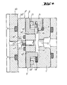
- Figure 3 shows a further embodiment of the invention in which the leakage spaces 31 ', 33', 34 'outside the mechanical seals 15 ', 16' and 17 ', 18' additionally with annular leakage seals 35 ', 36' are sealed from the environment 37 'of the rotary feedthrough. So that can be unavoidable by the mechanical seals (15 ', 16' and 17 ', 18') leaking fluid not in the area (37 ') outside the rotary union.
- Figure 4 shows an alternative embodiment of the embodiment shown in Figures 1 and 2
- the rotary feedthrough in which the rotor 4 "is designed in two parts, consists of a hollow cylindrical core 38 "and halfway up the core 28" pushed ring 39 “ together, so that the two parts 38 “and 39” of the rotor 4 "together in approximately the same outer Have shape as the one-piece rotor 4 of Figures 1 and 2.
- the deferred ring 39 " has a clearance to the core 38 "and the transition between the two elements 38 ", 39” is sealed with the help of two O-rings 40 "and 41” against the environment.
- the deferred Ring 39 has flow holes for the fluid which are aligned with the bores of the core 38", so that the fluid can flow into the shaft.
- the deferred ring 39 "with the Wave and the core 38 "of the rotor 4" can rotate with the help of two on opposite Side of the rotary feedthrough arranged driver pins 42 "connected to the core 38".
- the annular projection 7 of the one-piece rotor 4 also form the end faces of the deferred Rings 39 "sealing surfaces 16", 18 "rotor 4".
Landscapes
- Engineering & Computer Science (AREA)
- General Engineering & Computer Science (AREA)
- Mechanical Engineering (AREA)
- Joints Allowing Movement (AREA)
- Sealing Devices (AREA)
- Sealing Using Fluids, Sealing Without Contact, And Removal Of Oil (AREA)
- Branch Pipes, Bends, And The Like (AREA)
- Mechanical Sealing (AREA)
- Sowing (AREA)
- Ultra Sonic Daignosis Equipment (AREA)
- Rotary Pumps (AREA)
Abstract
Description
Die Erfindung betrifft eine radiale Drehdurchführung mit mindestens einem Rotor und mindestens einem feststehenden Teil, wobei der mindestens eine Rotor mindestens zwei axial beabstandete Dichtflächen aufweist und wobei zwischen dem feststehenden Teil und dem Rotor zwei Gleitringe mit insgesamt mindestens zwei Dichtflächen angeordnet sind, wobei die Dichtflächen der Gleitringe mit den Rotordichtflächen zusammenwirken, und mit mindestens einem radialen Zufuhrdurchgang zwischen den Paaren zusammenwirkender Dichtflächen.The invention relates to a radial rotary feedthrough with at least one rotor and at least a fixed part, wherein the at least one rotor at least two axially spaced Has sealing surfaces and wherein between the fixed part and the rotor two slip rings are arranged with a total of at least two sealing surfaces, wherein the sealing surfaces of the sliding rings interact with the rotor sealing surfaces, and with at least one radial feed passage between the pairs of cooperating sealing surfaces.
Drehdurchführungen für Fluide von einem feststehenden in ein drehendes Maschinenteil sind aus dem Stand der Technik bekannt. Das von allen Drehdurchführungen zu lösende technische Problem besteht darin, einen dichten Übergang zwischen zwei sich gegeneinander drehenden Teilen herzustellen.Rotary unions for fluids from a fixed to a rotating machine part are off known in the art. The technical problem to be solved by all rotary feedthroughs is to make a tight transition between two mutually rotating parts.
Die aus dem Stand der Technik bekannten Drehdurchführungen sind entweder axiale Durchführungen, bei denen das Fluid entlang der Drehachse oder parallel dazu in das drehende Maschinenteil überführt wird, oder radiale Drehdurchführungen. Die japanische Patentschrift JP 09196265 A, von welcher die vorliegende Anmeldung ausgeht, zeigt eine solche radiale Drehdurchführung, bei der das Fluid in einer Richtung senkrecht zur Drehachse des drehenden Maschinenteils von dem feststehenden Maschinenteil in das drehende Teil überführt wird. Dabei sind an dem sich drehenden Teil, nachfolgend auch als Rotor bezeichnet, zwei ringförmige Ansätze vorgesehen, die axiale Dichtflächen aufweisen, deren Flächennormalen in Richtung der Drehachse zeigen und die ringförmig um die Drehachse des Rotors umlaufen. Dabei sind die Dichtflächen der beiden ringförmigen Ansätze einander zugewandt. Auf den Dichtflächen des Rotors stützen sich die Dichtflächen zweier Gleitringe ab. Die Gleitringe sind gegen das Mitdrehen mit dem Rotor an dem feststehenden Teil gesichert und ihre Dichtflächen werden mit Hilfe von sich gegen einen Abschnitt des feststehenden Teils abstützenden Federn gegen die Dichtflächen des Rotors gedrückt. Die Zuführung des Fluids erfolgt durch einen Kanal zwischen den beiden Gleitringen in einer Richtung senkrecht zur Drehachse des Rotors. Ein Austreten des Fluids wird so mit Hilfe der eben aufeinanderliegenden Dichtflächen des Rotors und der beiden Gleitringe und durch Dichtungen zwischen dem feststehenden Teil und den Gleitringen verhindert.The rotary feedthroughs known from the prior art are either axial feedthroughs, in which the fluid along the axis of rotation or parallel to it in the rotating machine part is transferred or radial rotary unions. Japanese Patent Publication JP 09196265 A, of which emanates the present application, shows such a radial rotary feedthrough, in which the fluid in a direction perpendicular to the axis of rotation of the rotating machine part of the fixed Machine part is transferred to the rotating part. Here are at the turning Part, hereinafter also referred to as rotor, two annular projections provided, the axial sealing surfaces have, the surface normal in the direction of the axis of rotation and the annular order rotate the axis of rotation of the rotor. In this case, the sealing surfaces of the two annular projections facing each other. On the sealing surfaces of the rotor, the sealing surfaces of two sliding rings are based from. The sliding rings are secured against rotation with the rotor on the fixed part and their sealing surfaces are supported by themselves against a portion of the fixed part Pressed springs against the sealing surfaces of the rotor. The supply of the fluid takes place through a channel between the two sliding rings in a direction perpendicular to the axis of rotation of the Rotor. A leakage of the fluid is so with the help of the superimposed sealing surfaces of the Rotor and the two sliding rings and seals between the fixed part and the Prevents sliding rings.
Die aus der JP 09196265 A bekannte Drehdurchführung hat einen sehr komplexen, voluminösen Aufbau. Der die Gleitdichtflächen tragende mit einer Welle verbundene Teil besteht aus zwei axial beabstandeten Rotorringen, denen jeweils ein Gleitring zugeordnet is. Die Rotorringe müssen abgedichtet auf der Welle fixiert sein. Jedem Rotorring ist ein eigener Gleitring zugeordnet, der zwar nicht mit rotiert, der jedoch axial schwimmend und federnd vorgespannt auf der Welle angeordnet ist, um unabhängig von etwaigen Bauteil- und Montagetoleranzen immer eine dichte Auflage seiner Gleitdichtflächen zu gewährleisten. Das feststehende Teil weist zur Lagerung und Abstützung der Gleitringe einen radial einwärts ragenden Bund auf, der zwischen den Gleitringen angeordnet ist und über Federn die Gleitringe an den Rotorring andrückt. Diese Bauweise beansprucht relativ viel Raum sowohl in axialer als auch in radialer Richtung.The rotary feedthrough known from JP 09196265 A has a very complex, voluminous Construction. The part carrying the Gleitdichtflächen connected to a shaft consists of two axially spaced rotor rings, each associated with a sliding ring. The rotor rings must be sealed be fixed on the shaft. Each rotor ring is assigned its own sliding ring, which is not with rotated, but axially floating and resiliently biased on the shaft is arranged to regardless of any component and assembly tolerances always a dense edition of its Gleitdichtflächen to ensure. The fixed part has for storage and support of the slip rings a radially inwardly projecting collar, which is arranged between the sliding rings and Press the sliding rings against the rotor ring via springs. This construction requires a lot Space in both the axial and in the radial direction.
Radiale (und auch axiale) Drehdurchführungen werden unter anderem für die interne Kühlmittelzufuhr bei Werkzeugmaschinen verwendet. Ein Nachteil dieser Drehdurchführungen liegt allerdings darin, daß sie relativ voluminös sind und an einer Werkzeugspindel entsprechend Platz benötigen. Dies ist insbesondere bei modernen Bearbeitungszentren störend, die ohnehin Platz für Werkzeugmagazine und Revolverköpfe benötigen. Auch eine Nachrüsten einer Kühlmittelzufuhr durch Austausch einer Spindel ohne Einrichtungen für Kühlmittelmittelzufuhr gegen eine Spindel mit entsprechenden Einrichtungen, scheitert oft an dem zusätzlich für die Drehdurchführung benötigten Platz.Radial (and also axial) rotary unions are used, among other things, for internal coolant supply used in machine tools. A disadvantage of these rotary joints is however in that they are relatively bulky and require space on a tool spindle. This is particularly disturbing in modern machining centers, which in any case accommodate tool magazines and turrets need. Also a retrofitting of a coolant supply by replacement a spindle without means for coolant supply against a spindle with corresponding Facilities, often fails due to the additional space required for the rotary feedthrough.
Gegenüber diesem Stand der Technik liegt der vorliegenden Erfindung die Aufgabe zugrunde, eine radiale Drehdurchführung konstruktiv so zu gestalten, daß ihr Einbau in Bearbeitungszentren und eine Nachrüstung an bestehenden Einrichtungen vereinfacht wird und nicht an dem geringen vorhandenen Platz scheitert.Compared to this prior art, the present invention has the object, a radial rotary feedthrough design so that their installation in machining centers and Retrofitting to existing facilities is simplified and not on the low existing Place fails.
Diese Aufgabe wird dadurch gelöst, daß eine radiale Drehdurchführung bereitgestellt wird mit mindestens einem Rotor und mindestens einem feststehenden Teil, wobei der mindestens eine Rotor mindestens zwei Dichtflächen aufweist und wobei zwischen dem feststehenden Teil und dem Rotor zwei Gleitringe mit insgesamt mindestens zwei Dichtflächen angeordnet sind, wobei die Dichtflächen der Gleitringe mit den Rotordichtflächen zusammenwirken, und mit mindestens einem radialen Zufuhrdurchgang zwischen den Paaren zusammenwirkender Dichtflächen, wobei die Normalen auf die Dichtflächen des Rotors axial voneinander weg weisen, wobei die Normalen auf die Dichtflächen der Gleitringe axial aufeinander zu gerichtet sind.This object is achieved in that a radial rotary feedthrough is provided with at least a rotor and at least one stationary part, wherein the at least one rotor has at least two sealing surfaces and wherein between the fixed part and the rotor two sliding rings are arranged with a total of at least two sealing surfaces, wherein the sealing surfaces the sliding rings cooperate with the rotor sealing surfaces, and with at least one radial feed passage between the pairs of cooperating sealing surfaces, the normal to the Have sealing surfaces of the rotor axially away from each other, the normal to the sealing surfaces of the Sliding rings are directed axially towards each other.
Bei dieser Ausgestaltung können die Gleitdichtflächen des Rotors an ein und demselben Bauteil angeordnet werden und ein besonderer Vorteil besteht bei dieser Konstruktion darin, daß sie mit einer verringerten axialen Höhe bereitgestellt werden kann.In this embodiment, the sliding sealing surfaces of the rotor on one and the same component be arranged and a particular advantage in this construction is that they are with a reduced axial height can be provided.
Besonders bevorzugt ist eine Ausführungsform der Erfindung, bei der die axiale Höhe, d. h. die Abmessung der Drehdurchführung in einer Richtung parallel zur Drehachse des Rotors weniger als 40 mm, vorzugsweise weniger als 20 mm und besonders bevorzugt 18 mm aufweist. Durch entsprechende Optimierung der einzelnen Bauteile ist dies bei gängigen Nenndurchmessern entsprechender Wellen von 20 mm bis etwa 100 mm auf Basis der erfindungsgemäßen Konstruktion ohne weiteres erreichbar.Particularly preferred is an embodiment of the invention in which the axial height, i. H. the dimension the rotary feedthrough in a direction parallel to the axis of rotation of the rotor less than 40 mm, preferably less than 20 mm and particularly preferably 18 mm. By appropriate Optimization of the individual components this is correspondingly at common nominal diameters Shafts of 20 mm to about 100 mm based on the construction according to the invention readily reachable.
Eine solche geringe axiale Bauhöhe ermöglicht den Einbau in Werkzeugmaschinen direkt zwischen den Spindellagern selbst bei kurzem Abstand zwischen den Lagern der Welle, und benötigt daher keinerlei zusätzlichen Raum. Aufgrund ihrer Anordnung zwischen den Lagern ist es sinnvoll wenn die an diesen Stellen verwendeten Drehdurchführungen vollständig leckfrei sind, um die benachbarten Lager nicht zu beeinträchtigen.Such a low axial height allows installation in machine tools directly between the spindle bearings even with a short distance between the bearings of the shaft, and therefore needed no additional space. Because of their arrangement between the camps, it makes sense if the rotary unions used at these points are completely leak-free to the neighboring ones Do not interfere with stock.
Um eine Beeinträchtigung benachbarter Bauelemente zu verhindern ist es deshalb zweckmäßig, wenn die axial außerhalb der Gleitringdichtungen liegenden Leckräume der Drehdurchführung mit ringförmigen gegen die Welle drückenden Leckraumdichtungen abgedichtet sind.In order to prevent an impairment of adjacent components, it is therefore expedient if the axially located outside of the mechanical seals leaks of the rotary feedthrough with annular sealed against the shaft leakage seals are sealed.
Generell ist es vorteilhaft, wenn das Verhältnis des Durchmessers der Welle zur axialen Höhe der Drehdurchführung größer als 1, vorzugsweise größer als 1,5 und besonders bevorzugt größer als 2 ist. Dies gewährleistet verhältnismäßig geringe Einbaumaße der Drehdurchführungen auch für große Wellendurchmesser.In general, it is advantageous if the ratio of the diameter of the shaft to the axial height of Rotary feedthrough greater than 1, preferably greater than 1.5 and more preferably greater than 2 is. This ensures relatively low installation dimensions of the rotary unions even for large Shaft diameter.
Zweckmäßig ist es, wenn das maximale Verhältnis zwischen der radialen Dicke der Drehdurchführung und dem Durchmesser der Welle kleiner als 1/3, vorzugsweise kleiner als 1/5 und besonders bevorzugt kleiner als 1/6 ist. So hält sich das radiale Einbaumaß auch bei verhältnismäßig großen Wellen in Grenzen.It is expedient if the maximum ratio between the radial thickness of the rotary feedthrough and the diameter of the shaft is less than 1/3, preferably less than 1/5 and especially preferably less than 1/6. Thus, the radial installation dimension holds even at relatively large Waves within limits.
Weiterhin ist es zweckmäßig, wenn der Rotor einstückig ausgeführt ist. Dies spart Zeit und Kosten bei der Herstellung und vor allem bei der Montage des Rotors.Furthermore, it is expedient if the rotor is made in one piece. This saves time and costs in the manufacture and especially in the assembly of the rotor.
Bevorzugt wird eine Ausführungsform der Erfindung, bei der der Rotor einen ringförmigen Ansatz aufweist, dessen Stirnseiten oder Teile davon die Dichtflächen bilden. Da beide Dichtflächen Teile des ringförmigen Ansatzes sind, wird weniger Platz in Anspruch genommen als bei Verwendung von je einem Träger für jede Dichtfläche. Darüber hinaus kann der ringförmige Ansatz in axialer Richtung relativ dünn ausgeführt werden, da die Dichtflächen auf den gegenüberliegenden Deckelflächen des ringförmigen Ansatzes liegen, so daß sich die auf die Dichtflächen ausgeübten Kräfte ausgleichen. Auch hierdurch wird axiale Bauhöhe eingespart. Die axiale Höhe des Ansatzes muß allerdings ausreichend sein, um zwischen den Gleitdichtflächen, die durch die Stirnseiten des Ansatzes gebildet werden, noch eine radiale Bohrung bzw. einen Durchgang, der auch einen nichtrunden, schmalen Querschnitt z. B. eines Langlochs haben kann, unterbringen zu können. An embodiment of the invention is preferred in which the rotor has an annular projection has, whose end faces or parts thereof form the sealing surfaces. Because both sealing surfaces parts of the annular approach, less space is required than when using one support for each sealing surface. In addition, the annular approach in the axial direction be carried out relatively thin, since the sealing surfaces on the opposite cover surfaces of the annular approach, so that compensate for the forces exerted on the sealing surfaces forces. This also saves axial height. However, the axial height of the approach must be sufficient to be between the sliding surfaces formed by the end faces of the neck become, still a radial bore or a passage, which also a non-round, narrow Cross-section z. B. can have a long hole to accommodate.
In einer alternativen Ausführungsform der Erfindung ist der Rotor mehrteilig ausgeführt, wobei er mindestens einen Kern und mindestens einen aufgeschobenen Ring aufweist. Dabei bilden die Stirnseiten des aufgeschobenen Rings oder Teile davon die Dichtflächen. Diese Ausgestaltung ist vorteilhaft, da sie eine einfachere Herstellung und Montage des Rotors erlaubt. Der aufgeschobene Ring bildet dabei vorzugsweise den ringförmigen Ansatz oder weist den ringförmigen Ansatz auf, an welchem die axialen Dichtflächen angeordnet sind.In an alternative embodiment of the invention, the rotor is designed in several parts, wherein he has at least one core and at least one deferred ring. Here are the End faces of the pushed ring or parts thereof the sealing surfaces. This embodiment is advantageous because it allows easier manufacture and installation of the rotor. The deferred Ring preferably forms the annular projection or has the annular projection on which the axial sealing surfaces are arranged.
Besonders vorteilhaft ist es dabei, wenn der mindestens eine aufgeschobene Ring über mindestens einem Mitnehmerstift mit dem mindestens einen Kern verbunden ist. So sind die Drehbewegungen des Kerns und des aufgeschobenen Rings aneinander gekoppelt.It is particularly advantageous if the at least one deferred ring over at least a driving pin is connected to the at least one core. So are the rotational movements the core and the deferred ring coupled together.
Besonders bevorzugt wird eine Ausführungsform der Erfindung, bei der das feststehende Teil den Querschnitt eines U-Profils hat und eine ringförmig umlaufende Klammer bildet, wobei die Schenkel des U-Profils axial von außen die Gleitringe und den Rotor oder Teile davon umgreifen. Auf diese Weise entsteht eine besonders kompakte Bauform.Particularly preferred is an embodiment of the invention, in which the fixed part of the Cross-section of a U-profile and forms an annular circumferential clamp, wherein the legs of the U-profile axially from the outside around the seal rings and the rotor or parts thereof. To this This results in a particularly compact design.
Dabei ist es zweckmäßig, wenn das feststehende Teil aus einem Ring mit L-Profil-Querschnitt und
einem daran befestigten Ring besteht, welcher das L-Profil zu einem U-Profil ergänzt. So kann das
feststehende Teil bis auf den Ring einstückig ausgeführt werden. Nach der Montage der übrigen
Teile wird der Ring befestigt und ergänzt, das L-Profil zu einem U-Profil, das die Gleitringe und den
Rotor oder Teile davon umgreift. Vorzugsweise weist der Ring an seiner Außenseite ein Gewinde
auf, mit Hilfe dessen der Ring in das L-Profil eingeschraubt werden kann. Alternativ kann er mit zusätzlichen
Schrauben an dem L-Profil befestigt werden. Ebenso ist eine Schweiß-, Löt- oder Klebverbindung
denkbar.
Zweckmäßigerweise erstrecken sich dabei sowohl der (einstückige) Rotor als auch das feststehende
Teil der Drehdurchführung axial über die volle Höhe Drehdurchführung, wobei der Rotor radial innerhalb
des feststehenden Teil angeordnet ist und ein ringförmiger Ansatz des Rotors radial mit
einwärts ragenden U-Schenkeln des feststehenden Teil überlappt und zwischen diesen überlappenden
Teilen die Gleitringe angeordnet sind, von denen einer auch einstückig mit dem feststehenden
Teil ausgebildet sein könnteIt is expedient if the fixed part consists of a ring with L-profile cross-section and a ring attached thereto, which complements the L-profile to a U-profile. So the fixed part can be carried out in one piece up to the ring. After assembly of the remaining parts, the ring is attached and completed, the L-profile to a U-profile, which surrounds the seal rings and the rotor or parts thereof. Preferably, the ring has on its outer side a thread by means of which the ring can be screwed into the L-profile. Alternatively, it can be attached to the L-profile with additional screws. Likewise, a welding, soldering or adhesive connection is conceivable.
Expediently, both the (one-piece) rotor and the fixed part of the rotary leadthrough extend axially over the full height of the rotary leadthrough, wherein the rotor is arranged radially inside the fixed part and an annular projection of the rotor radially with inwardly projecting U-legs of the fixed part overlapped and between these overlapping parts, the sliding rings are arranged, one of which could also be formed integrally with the fixed part
Vorzugsweise sind die Gleitringdichtungen hydrostatisch kompensiert. Wird ein Gleitring mit gegenüberliegenden Stirnflächen gleicher Größe von einem Fluid, das mit Druck beaufschlagt ist, umflossen, so sind die von beiden Seiten auf den Gleitring wirkenden Kräfte gleich groß und der Gleitring ist kräftefrei. Der hydrostatische Druck auf einer Dichtfläche eines Gleitrings, die auf der entgegengesetzten Gleitfläche eines rotierenden Teils abläuft, nimmt mit dem Abstand von der mit Fluid gefüllten Kammer ab und beträgt am anderen Ende der Gleitrings null. Daher ist bei gleicher Fläche der Ober- und Unterseiten des Gleitrings die Kraft auf die Seite der Gleitfläche geringer als die Kraft auf die gegenüberliegende Seite. Wird dieses Kräfteungleichgewicht nicht ausgeglichen, so wird der Gleitring durch das unter Druck stehende Fluid zusätzlich zu den Federn sehr fest gegen die zweite Dichtfläche gedrückt und kann im Extremfall trocken laufen und sich fest fressen. Dies kann vermieden werden, indem die Größen der vom Fluid umflossenen Flächen auf der Ober- und Unterseite des Gleitrings so bemessen werden, daß sich die angreifenden Kräfte ausgleichen, obwohl der Druck auf die Gleitflächen in radialer Richtung abfällt. Dabei ist es vorteilhaft, wenn die Gleitringdichtungen fast vollständig, d. h. in der Praxis zwischen 90 % und 100%, vorzugsweise zu etwa 95 % hydrostatisch kompensiert sind.Preferably, the mechanical seals are hydrostatically compensated. Will a slip ring with opposite Equal sized end faces are surrounded by a pressurized fluid. Thus, the forces acting on the sliding ring from both sides are equal and the sliding ring is free of energy. The hydrostatic pressure on a sealing surface of a sliding ring, on the opposite Sliding surface of a rotating part expires, increases with the distance from that with fluid filled chamber and is zero at the other end of the slip ring. Therefore, with the same area the upper and lower sides of the sliding ring, the force on the side of the sliding surface less than the force on the opposite side. If this power imbalance is not balanced, then the Sliding ring by the pressurized fluid in addition to the springs very firmly against the second Pressed sealing surface and can run dry in extreme cases and eat firmly. This can be avoided are determined by the sizes of the surfaces surrounded by the fluid on the top and bottom the sliding ring are sized so that the attacking forces compensate, although the Pressure on the sliding surfaces in the radial direction drops. It is advantageous if the mechanical seals almost completely, d. H. in practice between 90% and 100%, preferably about 95% hydrostatically compensated.
Für die Durchführung bestimmter Fluide wird eine Ausführungsform der Erfindung bevorzugt, bei der die Gleitringe aus einer technischen Keramik oder Hartmetall hergestellt sind. Solche Keramiken oder auch Hartmetalle sind hochfest und besitzen gute Gleiteigenschaften, während sie nur einem geringen Verschleiß unterliegen. Alternativ dazu können die Gleitringe wie aus dem Stand der Technik bekannt aus einer Stahl/Bronze Legierung hergestellt werden.For carrying out certain fluids, an embodiment of the invention is preferred in which the slip rings are made of a technical ceramic or tungsten carbide. Such ceramics or hard metals are high strength and have good sliding properties, while only one subject to low wear. Alternatively, the slip rings as in the prior Technique known to be made of a steel / bronze alloy.
Weitere Merkmale, Vorzüge und Anwendungsmöglichkeiten der vorliegenden Erfindung ergeben
sich aus der folgenden Beschreibung einer bevorzugten Ausführungsform zusammen mit den beiliegenden
Figuren:
Die in den Figuren 1 und 2 dargestellte Ausführungsform der erfindungsgemäßen Drehdurchführung
besteht aus vier wesentlichen Funktionselementen, dem feststehenden Teil 1, den Gleitringen 2, 3
sowie dem Rotor oder drehenden Teil 4. Das feststehende Teil 1 der Drehdurchführung ist so ausgeführt,
daß es eine ringförmig umlaufende Klammer bildet, die die anderen Elemente zumindest
teilweise umgreift und zusammenhält. Um eine Montage der beiden Gleitringe 2, 3 und des Rotors 4
zu ermöglichen und um diese beiderseits abzustützen, ist die obere Stirnseite des feststehenden
Teils 1 aus einem einschraubbaren Ring 5 vorgesehen. Damit über das Gewinde des Ringes 5 kein
Fluid nach außen dringen kann, ist das Gewinde am unteren Ende mit einem umlaufenden O-Ring 6
abgedichtet. Der Rotor 4 ist in der gezeigten Ausführungsform einstückig ausgeführt und weist eine
im wesentlichen hohlzylindrische Form auf, wobei auf der Außenseite des Zylinders symmetrisch in
der Hälfte der Höhe ein ringförmiger Ansatz 7 vorgesehen ist. Der hohlzylinderförmige Rotor 4 kann
über eine Hohlwelle geschoben werden, wobei zwei radial umlaufende O-Ringdichtungen 8, 9 den
Rotor gegen die Welle abdichten. Wenn der Rotor zusätzlich zu seinem Sitz auf den O-Ringen 8, 9
auf der Welle fixiert werden soll, so kann er durch Kleben oder Schrauben befestigt werden. Feststehender
Teil 1 und Rotor 4 haben in etwa dieselbe axiale Höhe bzw. Länge und sind in derselben
Radialebene angeordnet. Sie definieren dadurch auch die gesamte axiale Höhe der Drehdurchführung.The illustrated in Figures 1 and 2 embodiment of the rotary feedthrough according to the invention
consists of four essential functional elements, the
Um ein Einströmen des Fluids in die Welle zu ermöglichen, ist der Rotor in der gezeigten Ausführungsform
mit zwei gegenüberliegend angeordneten Durchflußkanälen 10, 11 versehen, die symmetrisch
in der Mitte des ringförmigen Ansatzes 7 angeordnet sind. Es versteht sich, daß auch nur ein
Kanal oder mehrere über den Umfang verteilte Kanäle vorgesehen sein können, da der Raum 14
den Ansatz 7 als ein zusammenhängendes Volumen ringförmig umgibt.In order to allow the fluid to flow into the shaft, the rotor is in the illustrated embodiment
provided with two oppositely disposed
Um ein Austreten des Fluids zwischen dem Rotor 4 und der Welle zu verhindern, sind die O-Ringdichtungen
8, 9 in axialer Richtung auf beiden Seiten der Durchflußkanäle 10, 11 angeordnet.
Der Hohlzylinder des Rotors 4 ist im wesentlichen so bemessen, daß sein Außendurchmesser kleiner
ist als der Innendurchmesser des feststehenden Teils 1. Lediglich der ringförmige Ansatz 7 ragt
mit seinem Außendurchmesser in die von dem feststehenden Teil 1 gebildete ringförmige Klammer
hinein.To prevent leakage of the fluid between the
Ebenso wie der Rotor 4 weist das feststehende Teil 1 Durchflußkanäle 12, 13 auf, die die Außenseite
des feststehenden Teils 1 mit dem Innenraum 14 der von dem feststehenden Teil 1 gebildeten
Klammer verbinden. Aus dem Innenraum 14 der Klammer strömt das Fluid durch die Durchlaßkanäle
10, 11 des Rotors 4 in die Welle oder auch in umgekehrter Richtung.
Um eine Abdichtung des Innenraums 14 des feststehenden Elements 1 und der Durchflußkanäle
10,11,12,13 gegen den Außenbereich der Drehdurchführung zu erreichen, ist je eine Gleitringdichtung
oberhalb bzw. unterhalb der Durchlaßkanäle 10, 11, 12, 13 vorgesehen. Die Gleitringdichtungen
bestehen im wesentlichen aus jeweils zwei aufeinander ablaufenden bzw. gleitenden Gleitflächen
15, 16 bzw. 17, 18. Betrachtet man zunächst nur die obere Gleitringdichtung, so sieht man,
daß zwischen dem feststehenden Teil 1 und dem Rotor 4 ein L-förmiger Gleitring 2 angeordnet ist,
der mit geringem Spiel zwischen dem feststehenden 1 und dem drehenden Teil 4 sitzt. Einer der
Schenkel des L-förmigen Gleitrings 2 erstreckt senkrecht zur Drehachse radial nach außen. Der
Gleitring 2 weist an der Unterseite seines zur Drehachse senkrechten Schenkels einen ringförmig
umlaufenden Ansatz 30 auf, dessen ebene untere Fläche 15 die erste Dichtfläche der Gleitringdichtung
bildet. Die Dichtfläche 15 des Gleitrings 2 gleitet auf einer zweiten Gleitfläche 16, die von einer
der Deckelflächen des ringförmigen Ansatzes 7 des Rotors 4 gebildet wird. Die zweite Gleitringdichtung
unterhalb der Durchflußkanäle 10, 11, 12, 13 weist identische Merkmale wie die erste Gleitringdichtung
auf, jedoch ist sie um die Achse der Durchführungsöffnungen 10, 11, 12, 13 gespiegelt.
Damit die aufeinander gleitenden Dichtflächen 15, 16 bzw. 17, 18 dichtend wirken können, werden
die Gleitringe 2, 3 von über den Umfang der Dichtungen verteilten Federn 19, 20, die sich gegen das
feststehende Teil 1 abstützen gegen die Dichtflächen 16, 18 des ringförmigen Ansatzes 7 des Rotors
4 gedrückt. Die zweiten Seiten der L-förmigen Gleitringe 2, 3 sind mit Hilfe von ringförmigen
Dichtringen 21, 22 gegen das feststehende Teil gedichtet. Dabei sind die Dichtringe 21, 22 an den
zur Drehachse parallelen Schenkeln der L-förmigen Gleitringe 2, 3 angeordnet. Die Dichtringe 21,
22 weisen einen im wesentlichen U-förmigen Querschnitt auf, so daß sich die Gleitringe 2, 3 entlang
der Dichtringe 21, 22 leicht verschieben lassen. Um ein Mitdrehen der Gleitringe 2, 3 mit dem Rotor
4 zu verhindern, sind an dem feststehenden Teil 1 Stifte 23, 24 vorgesehen, die von dem oberen
bzw. dem unteren Schenkel des feststehenden Teils 1 in den Innenraum 14 hineinragen und durch
die Gleitringe 2, 3 durchgreifen, so daß sich diese nicht mehr gegen das feststehende Teil 1 verdrehen
lassen.As well as the
In order to achieve a seal of the interior 14 of the fixed
In der dargestellten Ausführungsform sind die Gleitringe 2, 3 aus einer technischen Keramik hergestellt.
Diese Keramiken zeigen gute Gleiteigenschaften während sie hochfest und abriebsarm sind.In the illustrated embodiment, the
Die L-förmige Ausgestaltung der Gleitringe 2, 3 und die Tatsache, daß ihre zur Drehachse senkrechten
Schenkel sowohl auf der Oberseite 27 als auch auf der Unterseite 28 von dem Fluid umflossen
sind, ermöglicht eine hydrostatische Kompensation der Gleitringe 2, 3. Die Funktion der hydrostatischen
Kompensation kann besonders einfach anhand der Figur 2 verstanden werden. Das radial
außenliegende Ende 25 des zur Drehachse senkrechten Schenkels des L-förmigen Gleitrings 3 hat
einen ausreichenden Abstand zum feststehenden Teil 1, so daß ein Kanal 26 gebildet wird, durch
den das Fluid aus der ringförmigen Kammer 24 auf die Oberseite 27 des zur Drehachse senkrechten
Schenkels strömen kann. Der Druck des Fluids ist dabei konstant und auf allen Seiten des Gleitrings
3 gleich groß. Die Kraft, die zusätzlich zu der Kraft der Federn 20 auf die Fläche 32 der Oberseite
27 des zur Drehachse senkrechten Schenkels wirkt ist gleich dem Produkt aus dem Druck und
der Größe der oberen Fläche 32. Auf der Unterseite 28 des zur Drehachse senkrechten Schenkels
greift ebenfalls eine hydrostatische Kraft an. Die Fläche der Unterseite 28 setzt sich aus zwei Abschnitten
zusammen: aus der Fläche 29 des Schenkels zwischen dem radial außenliegenden Ende
25 und dem Beginn des ringförmigen Ansatzes 30 und aus der Dichtfläche 15 des ringförmigen Ansatzes
30. Die auf die Fläche 29 wirkende Kraft ist wieder gleich dem Produkt aus dem Druck des
Fluids und der Größe der Fläche 29. Zum Berechnen der Kraft auf die Dichtfläche 15 hingegen muß
berücksichtigt werden, daß der Druck entlang der Dichtfläche 15 mit zunehmendem Abstand von der
Kammer 24 abnimmt. Die auf die Fläche wirkende Kraft berechnet sich dann als das Integral des
Drucks über die Fläche. Da die Dichtfläche 15 im Zusammenwirken mit der Dichtfläche 16 des Rotors
ein Austreten des Fluids in den hinter dem ringförmigen Ansatz 30 liegenden Bereich 31 verhindert,
wirkt dort keine hydrostatische Kraft auf den Schenkel. Die insgesamt auf die Unterseite 28 des
Schenkels wirkende Kraft ist gleich der Summe aus den beiden Beiträgen. Ist die Summe der Oberfläche
29 und der Dichtfläche 15 gleich der oberen Fläche 27 des Schenkels, so wirkt aufgrund der
Druckabnahme entlang der Dichtfläche 15 effektiv eine Kraft von oben auf den Schenkel. Die Position
der Dichtfläche wird nun so gewählt, daß sich die von unten und von oben auf den Schenkel wirkenden
Kräfte gerade aufheben. Dieser Zustand wird als hydrostatische Kompensation bezeichnet.
Auch der zweite Gleitring 3 ist in der gezeigten Ausführungsform hydrostatisch kompensiert.The L-shaped configuration of the
Im kompensierten Zustand werden die Dichtringe 2, 3 nur von den Federn 19, 20 gegen die Dichtflächen
16, 18 des Rotors gedrückt, so daß ein Trockenlaufen der Gleitringdichtungen verhindert
wird.In the compensated state, the sealing rings 2, 3 only by the
Figur 3 zeigt eine weitere Ausführungsform der Erfindung bei der die Leckräume 31', 33', 34' außerhalb der Gleitringdichtungen 15', 16' bzw. 17', 18' zusätzlich mit ringförmigen Leckraumdichtungen 35', 36' gegenüber der Umgebung 37' der Drehdurchführung abgedichtet sind. So kann das unvermeidlich durch die Gleitringdichtungen (15', 16' bzw. 17', 18') austretende Fluid nicht in den Bereich (37') außerhalb der Drehdurchführung gelangen.Figure 3 shows a further embodiment of the invention in which the leakage spaces 31 ', 33', 34 'outside the mechanical seals 15 ', 16' and 17 ', 18' additionally with annular leakage seals 35 ', 36' are sealed from the environment 37 'of the rotary feedthrough. So that can be unavoidable by the mechanical seals (15 ', 16' and 17 ', 18') leaking fluid not in the area (37 ') outside the rotary union.
Figur 4 zeigt eine alternative Ausführungsform der in den Figuren 1 und 2 gezeigten Ausführungsform
der Drehdurchführung, bei der der Rotor 4" zweiteilig ausgeführt ist. Er setzt sich aus einem
hohlzylinderförmigen Kern 38" und einem auf halber Höhe des Kerns 28" aufgeschobenen Ring 39"
zusammen, so daß die beiden Teile 38" und 39" des Rotors 4" zusammen in etwa die gleiche äußere
Form haben wie der einteilige Rotor 4 aus den Figuren 1 und 2. Der aufgeschobene Ring 39"
weist ein Spiel gegenüber dem Kern 38" auf und der Übergang zwischen den beiden Elementen
38", 39" ist mit Hilfe zweier O-Ringe 40" und 41" gegen die Umgebung gedichtet. Der aufgeschobene
Ring 39" weist Durchflußbohrungen für das Fluid auf, die mit den Bohrungen des Kerns 38" fluchten,
so daß das Fluid in die Welle einfließen kann. Damit sich der aufgeschobene Ring 39" mit der
Welle und dem Kern 38" des Rotors 4" mitdrehen kann ist er mit Hilfe zweier auf gegenüberliegenden
Seiten der Drehdurchführung angeordneten Mitnehmerstiften 42" mit dem Kern 38" verbunden.
Wie bei dem ringförmigen Ansatz 7 des einteiligen Rotors 4 bilden auch die Stirnflächen des aufgeschobenen
Rings 39" die Dichtflächen 16", 18" des Rotors 4". Figure 4 shows an alternative embodiment of the embodiment shown in Figures 1 and 2
The rotary feedthrough, in which the
- 11
- feststehender Teilfixed part
- 22
- Gleitringsliding ring
- 33
- Gleitringsliding ring
- 44
- Rotorrotor
- 55
- Ringring
- 66
- O-RingO-ring
- 77
- ringförmiger Ansatzannular approach
- 88th
- O-RingdichtungO-ring seal
- 99
- O-RingdichtungO-ring seal
- 1010
- Durchflußkanalflow channel
- 1111
- Durchflußkanalflow channel
- 1212
- Durchlaßkanalpassageway
- 1313
- Durchlaßkanalpassageway
- 1414
- Innenrauminner space
- 1515
- Gleitflächesliding surface
- 1616
- Gleitflächesliding surface
- 1717
- Gleitflächesliding surface
- 1818
- Gleitflächesliding surface
- 1919
- Federfeather
- 2020
- Federfeather
- 2121
- Dichtringseal
- 2222
- Dichtringseal
- 2323
- Stiftpen
- 2424
- Stiftpen
- 2525
- außenliegendes Endeoutboard end
- 2626
-
Kanal 26
Channel 26 - 2727
- Oberseitetop
- 2828
- Unterseitebottom
- 2929
- Flächearea
- 3030
- ringförmiger Ansatzannular approach
- 3131
- Bereich hinter dem ringförmigen AnsatzArea behind the annular approach
- 3232
- Fläche der Oberseite 27Surface of the top 27
- 3333
- Bereich außerhalb der GleitringdichtungArea outside the mechanical seal
- 3434
- Bereich außerhalb der GleitringdichtungArea outside the mechanical seal
- 35'35 '
- Reibdichtungfriction seal
- 36'36 '
- Reibdichtungfriction seal
- 37'37 '
- Umgebung der DrehdurchführungEnvironment of the rotary union
- 38"38 "
- Kern des zweiteiligen RotorsCore of the two-piece rotor
- 39"39 "
- aufgeschobener Ringdeferred ring
- 40"40 "
- O-Ring-DichtungO-ring seal
- 41"41 "
- O-Ring-DichtungO-ring seal
- 42"42 "
- MitnehmerstiftCarrier pin
Claims (15)
Applications Claiming Priority (2)
| Application Number | Priority Date | Filing Date | Title |
|---|---|---|---|
| DE10349968 | 2003-10-24 | ||
| DE10349968A DE10349968A1 (en) | 2003-10-24 | 2003-10-24 | Radial rotary feedthrough |
Publications (2)
| Publication Number | Publication Date |
|---|---|
| EP1526316A1 true EP1526316A1 (en) | 2005-04-27 |
| EP1526316B1 EP1526316B1 (en) | 2007-01-03 |
Family
ID=34384485
Family Applications (1)
| Application Number | Title | Priority Date | Filing Date |
|---|---|---|---|
| EP04105011A Expired - Lifetime EP1526316B1 (en) | 2003-10-24 | 2004-10-13 | Radial rotary connection |
Country Status (9)
| Country | Link |
|---|---|
| US (1) | US7407198B2 (en) |
| EP (1) | EP1526316B1 (en) |
| JP (1) | JP4917256B2 (en) |
| KR (1) | KR101097654B1 (en) |
| CN (1) | CN100398897C (en) |
| AT (1) | ATE350613T1 (en) |
| DE (2) | DE10349968A1 (en) |
| ES (1) | ES2281756T3 (en) |
| TW (1) | TWI284724B (en) |
Cited By (3)
| Publication number | Priority date | Publication date | Assignee | Title |
|---|---|---|---|---|
| WO2007014666A3 (en) * | 2005-07-29 | 2007-05-18 | Wilo Ag | Slide ring seal |
| WO2009133115A1 (en) * | 2008-05-02 | 2009-11-05 | GAT Gesellschaft für Antriebstechnik mbH | High-performance rotary feedthrough |
| DE102012024557A1 (en) * | 2012-12-15 | 2014-06-18 | Lubova AG | Rotary joint for high pressure equipment for connection of non-rotating element with rotating element, has sealing rings in axial direction, which are additionally acted upon by spring pre-stress in axial direction by intermediate rings |
Families Citing this family (19)
| Publication number | Priority date | Publication date | Assignee | Title |
|---|---|---|---|---|
| DE102007032889A1 (en) | 2007-07-14 | 2009-01-15 | Mtu Aero Engines Gmbh | Sealing device for a coolant supply to a rotating spindle and a machine tool with such a sealing device |
| DE102007049932A1 (en) * | 2007-10-18 | 2009-04-23 | Agco Gmbh | Connection element for a fluid-carrying pivotable component |
| JP2010270173A (en) * | 2009-05-19 | 2010-12-02 | Nakanishi Metal Works Co Ltd | Acrylic rubber composition and sealing material |
| TWI426197B (en) * | 2010-05-13 | 2014-02-11 | Hon Hai Prec Ind Co Ltd | Rotary joint and rotary work table using the same |
| DE102011089472A1 (en) * | 2010-12-21 | 2012-06-21 | Bielomatik Leuze Gmbh + Co. Kg | Rotary union |
| DE102012101815A1 (en) | 2012-03-05 | 2013-09-05 | GAT Gesellschaft für Antriebstechnik mbH | Rotary union |
| DE102012101814A1 (en) | 2012-03-05 | 2013-09-05 | GAT Gesellschaft für Antriebstechnik mbH | Radial rotary feed through for transfer of free-flowing media between stationary and rotating machine portions, has rotatable shaft with two shaft ends, where latter shaft end is equipped with shaft bearing |
| DE102012006901B3 (en) | 2012-04-05 | 2013-10-10 | Ludwig Volk | Rotary union |
| US20140028016A1 (en) * | 2012-07-30 | 2014-01-30 | Dana Heavy Vehicle Systems Group, Llc | Rotary union for use with a fluid conduit |
| US9790863B2 (en) * | 2013-04-05 | 2017-10-17 | Honeywell International Inc. | Fluid transfer seal assemblies, fluid transfer systems, and methods for transferring process fluid between stationary and rotating components using the same |
| GB2513183B (en) * | 2013-04-19 | 2019-11-13 | Welleng Science & Tech Ltd | Rotary coupling |
| CN104279386B (en) * | 2013-07-12 | 2017-05-03 | 山东飞越机械有限公司 | Piston balance compensating high-speed and high-pressure rotary joint |
| DE102015110988A1 (en) | 2015-07-07 | 2017-01-12 | GAT Gesellschaft für Antriebstechnik mbH | Leak-reduced rotary feedthrough |
| CN107701112B (en) * | 2017-09-24 | 2024-03-01 | 深圳市阿特拉能源技术有限公司 | A high-efficient PDC drill bit for geological drilling |
| DE102018208574A1 (en) * | 2018-05-30 | 2019-12-05 | KSB SE & Co. KGaA | A shaft seal assembly |
| US20200217437A1 (en) * | 2019-01-07 | 2020-07-09 | Deublin Company | Rotary joint |
| CN111594679A (en) * | 2020-06-19 | 2020-08-28 | 江苏贝特管件有限公司 | End face sealing structure of rotation compensator and rotation compensator |
| CN114183079A (en) * | 2021-11-15 | 2022-03-15 | 河南黄河旋风股份有限公司 | Drill barrel with water adding and slag discharging functions |
| CN114135234B (en) * | 2021-12-13 | 2022-08-16 | 河南黄河旋风股份有限公司 | Drilling system capable of adaptively retracting and releasing water pipe |
Citations (7)
| Publication number | Priority date | Publication date | Assignee | Title |
|---|---|---|---|---|
| US3503469A (en) * | 1967-06-19 | 1970-03-31 | Licentia Gmbh | Bearing lubricating arrangement |
| US4192559A (en) * | 1978-04-28 | 1980-03-11 | Koppers Company, Inc. | Rotary union |
| US4408766A (en) * | 1982-11-29 | 1983-10-11 | Longyear Australia Pty. Ltd. | Rotary seal apparatus with dual self-centering annular face seals |
| US4635969A (en) * | 1985-05-31 | 1987-01-13 | The Johnson Corporation | Rotary joint with balanced seals |
| WO1988002663A1 (en) * | 1986-10-17 | 1988-04-21 | Alfa-Laval Separation Ab | Centrifugal separator |
| DE3927775A1 (en) * | 1988-08-27 | 1990-03-01 | Zahnradfabrik Friedrichshafen | Supplying rotating shaft with oil - involves shaft fitted with two end face sealing rings |
| JPH09196265A (en) * | 1996-01-19 | 1997-07-29 | Ritsukusu Kk | Rotary joint |
Family Cites Families (20)
| Publication number | Priority date | Publication date | Assignee | Title |
|---|---|---|---|---|
| DE1093149B (en) * | 1957-01-04 | 1960-11-17 | Chantiers De Bretagne Anciens | Sealing device for the lateral supply of a pressurized medium into the interior of a circumferential hollow body |
| FR1383037A (en) * | 1963-10-29 | 1964-12-24 | Hispano Suiza Sa | Improvements made to multi-channel joints, especially those for hydraulic circuits |
| GB1208793A (en) * | 1967-04-20 | 1970-10-14 | Stromag Maschf | An assembly for use in feeding pressure fluid through a stationary member to a rotary member |
| NL168770C (en) * | 1976-04-13 | 1982-05-17 | Ihc Holland Nv | SWIVEL COUPLING FOR TWO OR MORE PIPES FOR A TRANSFER BUOY. |
| FR2551832B1 (en) * | 1983-09-09 | 1985-11-29 | Pinay Jack | IMPROVEMENTS IN OR RELATING TO ROTATING FITTINGS |
| DE3806931C2 (en) * | 1987-03-31 | 1993-10-28 | Glyco Antriebstechnik Gmbh | Rotating union for the transfer of pressurized media from a stationary to a rotating machine part |
| GB2205621B (en) * | 1987-04-28 | 1990-11-21 | Glyco Antriebstechnik Gmbh | Hydrostatic rotary connector |
| US5052720A (en) * | 1988-08-18 | 1991-10-01 | Tokyo Sharyo Seizo Kabushiki Kaisha | Swivel joint for high pressure fluid |
| DE4133262A1 (en) * | 1991-10-08 | 1993-04-15 | Siegfried Gulde | Pressure medium feed from rotary distributor to shaft - has ring chamber with facing radial side surfaces, formed as sealing faces, and with sealing rings |
| NO177779C (en) * | 1993-07-06 | 1995-11-22 | Statoil As | Sealing device for a swivel |
| NO177780C (en) * | 1993-07-06 | 1995-11-22 | Statoil As | Fluid transfer swivel |
| US5702130A (en) * | 1995-06-12 | 1997-12-30 | Framo Engineering As | Fluid flow connector |
| GB2306588B (en) * | 1995-11-01 | 1999-06-30 | Framo Eng As | Sealing arrangement |
| DE19621020C2 (en) * | 1996-05-24 | 2002-02-07 | Gat Gmbh | Rotary union for high pressures and high relative speeds |
| GB2321508A (en) * | 1997-01-22 | 1998-07-29 | Single Buoy Moorings | Sealing arrangement in a swivel joint |
| JPH11336970A (en) | 1998-05-21 | 1999-12-07 | Nippon Pillar Packing Co Ltd | Rotary joint device |
| DE19932355B4 (en) * | 1999-07-10 | 2010-07-15 | GAT Gesellschaft für Antriebstechnik mbH | Rotary feedthrough for changing media |
| JP3560144B2 (en) * | 2000-06-19 | 2004-09-02 | 日本ピラー工業株式会社 | Multi-channel rotary joint |
| JP3555936B2 (en) * | 2000-07-03 | 2004-08-18 | 日本ピラー工業株式会社 | Multi-channel rotary joint |
| JP3580774B2 (en) | 2000-12-05 | 2004-10-27 | 日本ピラー工業株式会社 | Multi-channel rotary joint |
-
2003
- 2003-10-24 DE DE10349968A patent/DE10349968A1/en not_active Withdrawn
-
2004
- 2004-10-13 AT AT04105011T patent/ATE350613T1/en not_active IP Right Cessation
- 2004-10-13 ES ES04105011T patent/ES2281756T3/en not_active Expired - Lifetime
- 2004-10-13 EP EP04105011A patent/EP1526316B1/en not_active Expired - Lifetime
- 2004-10-13 DE DE502004002518T patent/DE502004002518D1/en not_active Expired - Lifetime
- 2004-10-15 US US10/966,557 patent/US7407198B2/en not_active Expired - Lifetime
- 2004-10-22 JP JP2004308253A patent/JP4917256B2/en not_active Expired - Fee Related
- 2004-10-22 KR KR1020040084898A patent/KR101097654B1/en not_active Expired - Lifetime
- 2004-10-22 TW TW093132215A patent/TWI284724B/en not_active IP Right Cessation
- 2004-10-25 CN CNB2004100841639A patent/CN100398897C/en not_active Expired - Fee Related
Patent Citations (7)
| Publication number | Priority date | Publication date | Assignee | Title |
|---|---|---|---|---|
| US3503469A (en) * | 1967-06-19 | 1970-03-31 | Licentia Gmbh | Bearing lubricating arrangement |
| US4192559A (en) * | 1978-04-28 | 1980-03-11 | Koppers Company, Inc. | Rotary union |
| US4408766A (en) * | 1982-11-29 | 1983-10-11 | Longyear Australia Pty. Ltd. | Rotary seal apparatus with dual self-centering annular face seals |
| US4635969A (en) * | 1985-05-31 | 1987-01-13 | The Johnson Corporation | Rotary joint with balanced seals |
| WO1988002663A1 (en) * | 1986-10-17 | 1988-04-21 | Alfa-Laval Separation Ab | Centrifugal separator |
| DE3927775A1 (en) * | 1988-08-27 | 1990-03-01 | Zahnradfabrik Friedrichshafen | Supplying rotating shaft with oil - involves shaft fitted with two end face sealing rings |
| JPH09196265A (en) * | 1996-01-19 | 1997-07-29 | Ritsukusu Kk | Rotary joint |
Non-Patent Citations (1)
| Title |
|---|
| PATENT ABSTRACTS OF JAPAN vol. 1997, no. 11 28 November 1997 (1997-11-28) * |
Cited By (3)
| Publication number | Priority date | Publication date | Assignee | Title |
|---|---|---|---|---|
| WO2007014666A3 (en) * | 2005-07-29 | 2007-05-18 | Wilo Ag | Slide ring seal |
| WO2009133115A1 (en) * | 2008-05-02 | 2009-11-05 | GAT Gesellschaft für Antriebstechnik mbH | High-performance rotary feedthrough |
| DE102012024557A1 (en) * | 2012-12-15 | 2014-06-18 | Lubova AG | Rotary joint for high pressure equipment for connection of non-rotating element with rotating element, has sealing rings in axial direction, which are additionally acted upon by spring pre-stress in axial direction by intermediate rings |
Also Published As
| Publication number | Publication date |
|---|---|
| ES2281756T3 (en) | 2007-10-01 |
| EP1526316B1 (en) | 2007-01-03 |
| DE10349968A1 (en) | 2005-05-25 |
| CN100398897C (en) | 2008-07-02 |
| ATE350613T1 (en) | 2007-01-15 |
| JP2005127518A (en) | 2005-05-19 |
| TW200523493A (en) | 2005-07-16 |
| KR20050039660A (en) | 2005-04-29 |
| KR101097654B1 (en) | 2011-12-22 |
| TWI284724B (en) | 2007-08-01 |
| DE502004002518D1 (en) | 2007-02-15 |
| US20050111770A1 (en) | 2005-05-26 |
| CN1626865A (en) | 2005-06-15 |
| US7407198B2 (en) | 2008-08-05 |
| JP4917256B2 (en) | 2012-04-18 |
Similar Documents
| Publication | Publication Date | Title |
|---|---|---|
| EP1526316B1 (en) | Radial rotary connection | |
| EP0840866B1 (en) | Rotary transmission leadthrough for high pressures and high relative speeds | |
| DE60101537T2 (en) | Cam mechanism with crossed roller bearings | |
| DE102009054794B4 (en) | Radial rotary feedthrough and socket for this | |
| EP2039975A2 (en) | Radial turning execution | |
| EP1069362A2 (en) | Rotatable connection for alternate mediums | |
| EP2994657B1 (en) | Grease-lubricated angular contact ball bearing | |
| DE19614385A1 (en) | Seal for an annular piston of a hydraulic clutch release device | |
| DE69310494T2 (en) | High speed slewing ring | |
| DE3316332C2 (en) | ||
| DE102015215296A1 (en) | Bearing assembly and bearing ring for rotatably supporting a first component relative to a second component and screw compressor with the bearing assembly or the bearing ring | |
| EP1639288B1 (en) | Rotating passage | |
| DE102008064456B4 (en) | power steering device | |
| EP4390186A1 (en) | Subsea turbine sealing system | |
| DE19815134B4 (en) | Spindle head for machine tools | |
| DE10332010B4 (en) | Rotary union | |
| DE102020212070A1 (en) | MECHANICAL SEAL DEVICE AND ARRANGEMENT OF A MECHANICAL SEAL DEVICE IN AN AXLE SUPPORT | |
| EP0812397B1 (en) | Frictional revolving joint | |
| DE10238415A1 (en) | Slide bearing for a shaft of an exhaust gas turbocharger | |
| DE3612495A1 (en) | THRUST BEARING / SEAL ARRANGEMENT | |
| DE10040211C2 (en) | Device for sealing drive shafts | |
| DE2818664C2 (en) | Sealing arrangement for a shaft feed-through | |
| DE202008002709U1 (en) | bearing arrangement | |
| DE8136101U1 (en) | "CLUTCH FOR FRICTIONAL ROTATING CONNECTION OF MACHINE PARTS, LIKE HUB AND SHAFT" | |
| EP1445518B1 (en) | Piston ring |
Legal Events
| Date | Code | Title | Description |
|---|---|---|---|
| PUAI | Public reference made under article 153(3) epc to a published international application that has entered the european phase |
Free format text: ORIGINAL CODE: 0009012 |
|
| AK | Designated contracting states |
Kind code of ref document: A1 Designated state(s): AT BE BG CH CY CZ DE DK EE ES FI FR GB GR HU IE IT LI LU MC NL PL PT RO SE SI SK TR |
|
| AX | Request for extension of the european patent |
Extension state: AL HR LT LV MK |
|
| 17P | Request for examination filed |
Effective date: 20050928 |
|
| AKX | Designation fees paid |
Designated state(s): AT BE BG CH CY CZ DE DK EE ES FI FR GB GR HU IE IT LI LU MC NL PL PT RO SE SI SK TR |
|
| GRAP | Despatch of communication of intention to grant a patent |
Free format text: ORIGINAL CODE: EPIDOSNIGR1 |
|
| GRAS | Grant fee paid |
Free format text: ORIGINAL CODE: EPIDOSNIGR3 |
|
| GRAA | (expected) grant |
Free format text: ORIGINAL CODE: 0009210 |
|
| AK | Designated contracting states |
Kind code of ref document: B1 Designated state(s): AT BE BG CH CY CZ DE DK EE ES FI FR GB GR HU IE IT LI LU MC NL PL PT RO SE SI SK TR |
|
| PG25 | Lapsed in a contracting state [announced via postgrant information from national office to epo] |
Ref country code: PL Free format text: LAPSE BECAUSE OF FAILURE TO SUBMIT A TRANSLATION OF THE DESCRIPTION OR TO PAY THE FEE WITHIN THE PRESCRIBED TIME-LIMIT Effective date: 20070103 Ref country code: NL Free format text: LAPSE BECAUSE OF FAILURE TO SUBMIT A TRANSLATION OF THE DESCRIPTION OR TO PAY THE FEE WITHIN THE PRESCRIBED TIME-LIMIT Effective date: 20070103 Ref country code: IE Free format text: LAPSE BECAUSE OF FAILURE TO SUBMIT A TRANSLATION OF THE DESCRIPTION OR TO PAY THE FEE WITHIN THE PRESCRIBED TIME-LIMIT Effective date: 20070103 Ref country code: FI Free format text: LAPSE BECAUSE OF FAILURE TO SUBMIT A TRANSLATION OF THE DESCRIPTION OR TO PAY THE FEE WITHIN THE PRESCRIBED TIME-LIMIT Effective date: 20070103 Ref country code: SI Free format text: LAPSE BECAUSE OF FAILURE TO SUBMIT A TRANSLATION OF THE DESCRIPTION OR TO PAY THE FEE WITHIN THE PRESCRIBED TIME-LIMIT Effective date: 20070103 Ref country code: DK Free format text: LAPSE BECAUSE OF FAILURE TO SUBMIT A TRANSLATION OF THE DESCRIPTION OR TO PAY THE FEE WITHIN THE PRESCRIBED TIME-LIMIT Effective date: 20070103 |
|
| REG | Reference to a national code |
Ref country code: GB Ref legal event code: FG4D Free format text: NOT ENGLISH |
|
| REF | Corresponds to: |
Ref document number: 502004002518 Country of ref document: DE Date of ref document: 20070215 Kind code of ref document: P |
|
| REG | Reference to a national code |
Ref country code: IE Ref legal event code: FG4D Free format text: LANGUAGE OF EP DOCUMENT: GERMAN |
|
| PG25 | Lapsed in a contracting state [announced via postgrant information from national office to epo] |
Ref country code: SE Free format text: LAPSE BECAUSE OF FAILURE TO SUBMIT A TRANSLATION OF THE DESCRIPTION OR TO PAY THE FEE WITHIN THE PRESCRIBED TIME-LIMIT Effective date: 20070403 |
|
| PG25 | Lapsed in a contracting state [announced via postgrant information from national office to epo] |
Ref country code: BG Free format text: LAPSE BECAUSE OF FAILURE TO SUBMIT A TRANSLATION OF THE DESCRIPTION OR TO PAY THE FEE WITHIN THE PRESCRIBED TIME-LIMIT Effective date: 20070404 |
|
| REG | Reference to a national code |
Ref country code: CH Ref legal event code: NV Representative=s name: AMMANN PATENTANWAELTE AG BERN |
|
| PG25 | Lapsed in a contracting state [announced via postgrant information from national office to epo] |
Ref country code: PT Free format text: LAPSE BECAUSE OF FAILURE TO SUBMIT A TRANSLATION OF THE DESCRIPTION OR TO PAY THE FEE WITHIN THE PRESCRIBED TIME-LIMIT Effective date: 20070604 |
|
| NLV1 | Nl: lapsed or annulled due to failure to fulfill the requirements of art. 29p and 29m of the patents act | ||
| ET | Fr: translation filed | ||
| GBV | Gb: ep patent (uk) treated as always having been void in accordance with gb section 77(7)/1977 [no translation filed] |
Effective date: 20070103 |
|
| REG | Reference to a national code |
Ref country code: IE Ref legal event code: FD4D |
|
| REG | Reference to a national code |
Ref country code: ES Ref legal event code: FG2A Ref document number: 2281756 Country of ref document: ES Kind code of ref document: T3 |
|
| PLBE | No opposition filed within time limit |
Free format text: ORIGINAL CODE: 0009261 |
|
| STAA | Information on the status of an ep patent application or granted ep patent |
Free format text: STATUS: NO OPPOSITION FILED WITHIN TIME LIMIT |
|
| PG25 | Lapsed in a contracting state [announced via postgrant information from national office to epo] |
Ref country code: GB Free format text: LAPSE BECAUSE OF FAILURE TO SUBMIT A TRANSLATION OF THE DESCRIPTION OR TO PAY THE FEE WITHIN THE PRESCRIBED TIME-LIMIT Effective date: 20070103 Ref country code: SK Free format text: LAPSE BECAUSE OF FAILURE TO SUBMIT A TRANSLATION OF THE DESCRIPTION OR TO PAY THE FEE WITHIN THE PRESCRIBED TIME-LIMIT Effective date: 20070103 |
|
| 26N | No opposition filed |
Effective date: 20071005 |
|
| PG25 | Lapsed in a contracting state [announced via postgrant information from national office to epo] |
Ref country code: RO Free format text: LAPSE BECAUSE OF FAILURE TO SUBMIT A TRANSLATION OF THE DESCRIPTION OR TO PAY THE FEE WITHIN THE PRESCRIBED TIME-LIMIT Effective date: 20070103 Ref country code: CZ Free format text: LAPSE BECAUSE OF FAILURE TO SUBMIT A TRANSLATION OF THE DESCRIPTION OR TO PAY THE FEE WITHIN THE PRESCRIBED TIME-LIMIT Effective date: 20070103 |
|
| BERE | Be: lapsed |
Owner name: GAT G.- FUR ANTRIEBSTECHNIK MBH Effective date: 20071031 |
|
| PG25 | Lapsed in a contracting state [announced via postgrant information from national office to epo] |
Ref country code: GR Free format text: LAPSE BECAUSE OF FAILURE TO SUBMIT A TRANSLATION OF THE DESCRIPTION OR TO PAY THE FEE WITHIN THE PRESCRIBED TIME-LIMIT Effective date: 20070404 |
|
| PG25 | Lapsed in a contracting state [announced via postgrant information from national office to epo] |
Ref country code: MC Free format text: LAPSE BECAUSE OF NON-PAYMENT OF DUE FEES Effective date: 20071031 |
|
| PG25 | Lapsed in a contracting state [announced via postgrant information from national office to epo] |
Ref country code: BE Free format text: LAPSE BECAUSE OF NON-PAYMENT OF DUE FEES Effective date: 20071031 |
|
| PG25 | Lapsed in a contracting state [announced via postgrant information from national office to epo] |
Ref country code: EE Free format text: LAPSE BECAUSE OF FAILURE TO SUBMIT A TRANSLATION OF THE DESCRIPTION OR TO PAY THE FEE WITHIN THE PRESCRIBED TIME-LIMIT Effective date: 20070103 |
|
| PG25 | Lapsed in a contracting state [announced via postgrant information from national office to epo] |
Ref country code: AT Free format text: LAPSE BECAUSE OF NON-PAYMENT OF DUE FEES Effective date: 20071013 |
|
| PG25 | Lapsed in a contracting state [announced via postgrant information from national office to epo] |
Ref country code: CY Free format text: LAPSE BECAUSE OF FAILURE TO SUBMIT A TRANSLATION OF THE DESCRIPTION OR TO PAY THE FEE WITHIN THE PRESCRIBED TIME-LIMIT Effective date: 20070103 |
|
| PG25 | Lapsed in a contracting state [announced via postgrant information from national office to epo] |
Ref country code: LU Free format text: LAPSE BECAUSE OF NON-PAYMENT OF DUE FEES Effective date: 20071013 |
|
| PG25 | Lapsed in a contracting state [announced via postgrant information from national office to epo] |
Ref country code: TR Free format text: LAPSE BECAUSE OF FAILURE TO SUBMIT A TRANSLATION OF THE DESCRIPTION OR TO PAY THE FEE WITHIN THE PRESCRIBED TIME-LIMIT Effective date: 20070103 Ref country code: HU Free format text: LAPSE BECAUSE OF FAILURE TO SUBMIT A TRANSLATION OF THE DESCRIPTION OR TO PAY THE FEE WITHIN THE PRESCRIBED TIME-LIMIT Effective date: 20070704 |
|
| PGFP | Annual fee paid to national office [announced via postgrant information from national office to epo] |
Ref country code: FR Payment date: 20111118 Year of fee payment: 8 Ref country code: ES Payment date: 20111125 Year of fee payment: 8 |
|
| REG | Reference to a national code |
Ref country code: FR Ref legal event code: ST Effective date: 20130628 |
|
| PG25 | Lapsed in a contracting state [announced via postgrant information from national office to epo] |
Ref country code: FR Free format text: LAPSE BECAUSE OF NON-PAYMENT OF DUE FEES Effective date: 20121031 |
|
| PGFP | Annual fee paid to national office [announced via postgrant information from national office to epo] |
Ref country code: CH Payment date: 20131021 Year of fee payment: 10 |
|
| REG | Reference to a national code |
Ref country code: ES Ref legal event code: FD2A Effective date: 20140411 |
|
| PG25 | Lapsed in a contracting state [announced via postgrant information from national office to epo] |
Ref country code: ES Free format text: LAPSE BECAUSE OF NON-PAYMENT OF DUE FEES Effective date: 20121014 |
|
| REG | Reference to a national code |
Ref country code: CH Ref legal event code: PL |
|
| PG25 | Lapsed in a contracting state [announced via postgrant information from national office to epo] |
Ref country code: CH Free format text: LAPSE BECAUSE OF NON-PAYMENT OF DUE FEES Effective date: 20141031 Ref country code: LI Free format text: LAPSE BECAUSE OF NON-PAYMENT OF DUE FEES Effective date: 20141031 |
|
| PGFP | Annual fee paid to national office [announced via postgrant information from national office to epo] |
Ref country code: IT Payment date: 20161024 Year of fee payment: 13 |
|
| PG25 | Lapsed in a contracting state [announced via postgrant information from national office to epo] |
Ref country code: IT Free format text: LAPSE BECAUSE OF NON-PAYMENT OF DUE FEES Effective date: 20171013 |
|
| REG | Reference to a national code |
Ref country code: DE Ref legal event code: R082 Ref document number: 502004002518 Country of ref document: DE Representative=s name: WITHERS & ROGERS LLP, DE Ref country code: DE Ref legal event code: R081 Ref document number: 502004002518 Country of ref document: DE Owner name: MOOG GAT GMBH, DE Free format text: FORMER OWNER: GAT GESELLSCHAFT FUER ANTRIEBSTECHNIK MBH, 65201 WIESBADEN, DE |
|
| PGFP | Annual fee paid to national office [announced via postgrant information from national office to epo] |
Ref country code: DE Payment date: 20231020 Year of fee payment: 20 |
|
| REG | Reference to a national code |
Ref country code: DE Ref legal event code: R071 Ref document number: 502004002518 Country of ref document: DE |