EP1526257A2 - Dispositif de frein moteur pour un moteur à combustion interne à 4 temps - Google Patents
Dispositif de frein moteur pour un moteur à combustion interne à 4 temps Download PDFInfo
- Publication number
- EP1526257A2 EP1526257A2 EP04023313A EP04023313A EP1526257A2 EP 1526257 A2 EP1526257 A2 EP 1526257A2 EP 04023313 A EP04023313 A EP 04023313A EP 04023313 A EP04023313 A EP 04023313A EP 1526257 A2 EP1526257 A2 EP 1526257A2
- Authority
- EP
- European Patent Office
- Prior art keywords
- valve
- engine
- exhaust
- control
- control piston
- Prior art date
- Legal status (The legal status is an assumption and is not a legal conclusion. Google has not performed a legal analysis and makes no representation as to the accuracy of the status listed.)
- Granted
Links
Images


Classifications
-
- F—MECHANICAL ENGINEERING; LIGHTING; HEATING; WEAPONS; BLASTING
- F01—MACHINES OR ENGINES IN GENERAL; ENGINE PLANTS IN GENERAL; STEAM ENGINES
- F01L—CYCLICALLY OPERATING VALVES FOR MACHINES OR ENGINES
- F01L13/00—Modifications of valve-gear to facilitate reversing, braking, starting, changing compression ratio, or other specific operations
- F01L13/06—Modifications of valve-gear to facilitate reversing, braking, starting, changing compression ratio, or other specific operations for braking
- F01L13/065—Compression release engine retarders of the "Jacobs Manufacturing" type
-
- F—MECHANICAL ENGINEERING; LIGHTING; HEATING; WEAPONS; BLASTING
- F01—MACHINES OR ENGINES IN GENERAL; ENGINE PLANTS IN GENERAL; STEAM ENGINES
- F01L—CYCLICALLY OPERATING VALVES FOR MACHINES OR ENGINES
- F01L1/00—Valve-gear or valve arrangements, e.g. lift-valve gear
- F01L1/12—Transmitting gear between valve drive and valve
- F01L1/14—Tappets; Push rods
- F01L1/146—Push-rods
-
- F—MECHANICAL ENGINEERING; LIGHTING; HEATING; WEAPONS; BLASTING
- F01—MACHINES OR ENGINES IN GENERAL; ENGINE PLANTS IN GENERAL; STEAM ENGINES
- F01L—CYCLICALLY OPERATING VALVES FOR MACHINES OR ENGINES
- F01L1/00—Valve-gear or valve arrangements, e.g. lift-valve gear
- F01L1/12—Transmitting gear between valve drive and valve
- F01L1/18—Rocking arms or levers
- F01L1/181—Centre pivot rocking arms
-
- F—MECHANICAL ENGINEERING; LIGHTING; HEATING; WEAPONS; BLASTING
- F01—MACHINES OR ENGINES IN GENERAL; ENGINE PLANTS IN GENERAL; STEAM ENGINES
- F01L—CYCLICALLY OPERATING VALVES FOR MACHINES OR ENGINES
- F01L1/00—Valve-gear or valve arrangements, e.g. lift-valve gear
- F01L1/26—Valve-gear or valve arrangements, e.g. lift-valve gear characterised by the provision of two or more valves operated simultaneously by same transmitting-gear; peculiar to machines or engines with more than two lift-valves per cylinder
-
- F—MECHANICAL ENGINEERING; LIGHTING; HEATING; WEAPONS; BLASTING
- F01—MACHINES OR ENGINES IN GENERAL; ENGINE PLANTS IN GENERAL; STEAM ENGINES
- F01L—CYCLICALLY OPERATING VALVES FOR MACHINES OR ENGINES
- F01L2820/00—Details on specific features characterising valve gear arrangements
- F01L2820/02—Formulas
Definitions
- the invention relates to a motor dust brake device of a 4-stroke reciprocating internal combustion engine with features according to the preamble of claim 1.
- the invention is based on EP 0736672 B1.
- the relevant outlet valve is controllable via a rocker arm which can be actuated either directly or via a push rod.
- the parts of the braking device are considered either in the rocker arm or in the area of Pushrod integrated disclosed. For a more than two-valve engine but no Proposed solution.
- the engine-internal brake device has a control piston on which the exhaust valve is supported by its shaft.
- the spool is in a blind hole the Valve bridge axially movably recorded and supplied by a pressurized oil Control pressure chamber ago and possibly by an additional control spring in the direction Exhaust valve stem pressed.
- the pressure oil supply to the control pressure chamber via a valve bridge internal oil supply channel communicating with a toggle internal oil supply channel, in which latter one only in the direction of control pressure chamber permeable check valve is installed.
- From the control pressure chamber goes from a discharge channel, which at the Top of the valve bridge opens and its outlet opening through a simultaneously a stop for the valve bridge forming counter holder closed or for pressure relief of the control pressure chamber is releasable after lifting the valve bridge.
- the biasing force of the closing spring associated with this outlet valve is dimensioned such that during engine braking, when the throttle device is in throttle position due to the accumulated exhaust gas in conjunction with the pressure pulsations acting therein occurring exhaust back pressure results in an intermediate opening of the exhaust valve.
- This Intermediate opening is during each 4-stroke engine cycle with the engine-internal brake device Control technology automatically engageable such that after intermediate opening At the beginning of the 2-stroke closing valve inclined by the oil pressure and possibly also tax Druckfederbeetzscht nach Wegenden control piston intercepted and prevented from closing during the 2nd and 3rd bars, and until its beginning 4. cycle camshaft controlled opening is partially kept open.
- Exhaust counterpressure has its maximum when the throttle device is in the closed position, but is optionally by controlled and / or controlled opening of the throttle device degradable to reduce engine braking power and / or engine internal temperature Components to prevent their overheating.
- the cross section the oil supply channels in the rocker arm and the valve bridge and the pressure of the control pressure chamber supplied oils are coordinated so that during the said insectsffs the exhaust valve due to the nach Wegenden control piston magnifying control pressure chamber can at least almost completely fill with pressure oil and therefore at the end of the intermediate opening stroke, holding the exhaust valve in a trapped Partial opening position is possible.
- this engine dust brake device is equipped with a few, cheap manufacturable components feasible.
- the engine braking is automatic self-controlling without external influences only as a function of exhaust back pressure in shut off exhaust tract and demonstrably provides a very high engine braking power.
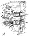
- Fig. 1 a detail of a 4-stroke reciprocating internal combustion engine is shown, the per cylinder 1 has at least one inlet valve (not shown) and two outlet valves 2, 3. 4, the installation space of the cylinder 1 with 5 is a piston working in the cylinder 1, with a 6 Cylinder head and designated 7 a cylinder cover.
- the outlet channels 8 of the cylinder 1 open into one or more exhaust manifolds and form with the latter part of the exhaust tract 9.
- a throttle device 10 is installed in the exhaust tract 9 as close as possible. This can, for example, by a throttle valve or a poppet valve or a Slider be formed. In most cases, a throttle is used.
- the throttle device 10 forms including its tax and / or regulatory bodies (on the next discussed in more detail below) a part of the engine dust brake device according to the invention and is used during engine braking operations to at least partially shut off the Exhaust tract and thereby caused upstream Aufstauung the exhaust gas.
- Another Part of the engine dust brake device is an engine-internal brake device 11 according to the invention Type, which is also discussed in more detail later.
- the inputs and Exhaust valves are controlled by a camshaft (not shown). Is this overhead, it acts directly on rocker arms. On the other hand, if it is lower, it is indirect via pushrods on the rocker arms.
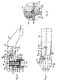
- Fig. 2 shows the version with below Camshaft in the area of the control of the two exhaust valves of a cylinder.
- Each of them is axially movable with its shaft 21 and 22 in the cylinder head 6 stored and by a closing spring 23 and 24, the one end on a cylinder head surface 25 and 26 and the other at one attached to the outlet valve stem 21 and 22 respectively Spring plate 27 and 28 is supported, with a certain biasing force F1 in the closing direction applied.
- Each of the two closing springs 23 and 24 can either by only one Spiral spring or two mutually coaxial coil springs be realized.
- each cylinder 1 associated with only one (2) of the two exhaust valves 2, 3, the other exhaust valve 3 is normally effective and operated, therefore also in conventional Way with the upper end of its shank on the bottom 29 of the valve bridge 20th supported.
- the one-outlet valve 2 associated with engine braking device 11 from a control piston 30, at which the outlet valve 2 with the upper End of his shaft 21 is supported.
- the control piston 30 is in a in the valve bridge 20th given blind bore 31 lickagearm axially movable guided and received by a supplied with pressure oil control pressure chamber 33 ago and possibly by an additional Control spring 32 in the direction of exhaust valve stem 21 pressed.
- the pressure oil supply to Control pressure chamber 33 via a in the rocker arm 13 and the bolt 18 with Abstweilkalotte 19 trained oil supply channel 34 and communicating with this Oil supply passage 35 in the valve bridge 20.
- In the valve bridge internal oil supply passage 35 is an oil built only in the direction of the control pressure chamber 33 permeable check valve 36.
- the pressure oil supply to the rocker arm 13 takes place from the outside either via a supply line in a channel in Kipphebellagerbolzen 15 and channels in the sliding bearing 16 or a supply line to the push rod 12 and a push rod internal channel, with which the rocker arm internal Oil supply channel 34 communicates.
- control pressure chamber 33 From the control pressure chamber 33 branches off a discharge channel 37, which at the top 38 of the Valve bridge 20 opens and its local outlet opening 39 by a simultaneously a stop for the valve bridge 20 forming counter holder 40 closed or for Pressure relief of the control pressure chamber 33 after lifting the valve bridge 20 can be released is.
- the biasing force F1 is the Closing spring 23 of that exhaust valve 2, which the engine-internal braking device 11 assigned is dimensioned such that during engine braking at throttle position befind another Throttle device 10 due to the accumulated in the exhaust gas in conjunction with the Exhaust counterpressure P2 occurring in this pressure pulsations an intermediate opening of the relevant outlet valve 2, and indeed - as shown in FIG. 9 - at the end the 1st clock (intake stroke) every 4-stroke cycle.
- this intermediate opening of the exhaust valve 2 is according to the invention control technology with the engine-internal engine brake device 11 automatically intervened in such a way that after the intermediate opening at the beginning of the 2.
- Exhaust counterpressure P2 reaches during engine braking when in the closed position Throttle device 10 its maximum.
- the control piston 30 of the engine-internal braking device 11 faces the front - to the exhaust valve 2 towards - a blind hole 41, with which he the upper end of the outlet valve stem 21st cap-like overlaps with game and is thus coupled to the exhaust valve 2.
- the control piston 30 is in the valve bridge internal blind bore 31 between two stops limited stroke movable. Here is the upper, the retracted home position defining Stop 42 in the case of the example of FIG. 3 to 5 by an annular Shoulder surface at the transition between two different diameter sections of the Blind bore 31 given, wherein the larger diameter portion of the control piston 30th receives and the smaller diameter portion forms the control pressure chamber 33 and also the control spring 32 receives laterally guided.
- control pressure spring 32 in This embodiment is taken centered in a rear blind hole 44 in the control piston 30 and supported there at the bottom 45. Changing is the control pressure spring 32 supported on the bottom 46 of the valve bridge internal blind bore 31. In the case of the example 6 to 8, however, the upper, the retracted basic position of the control piston predetermining stop 42 through the bottom 46 of the valve bridge internal blind bore educated. On the control piston 30, a coaxial pin 47 is arranged in this case on the back, with its rear end face 48 it is at the bottom 46 of the blind bore 31 to the plant comes.
- the discharge channel 37 is preferably centrally, so that the pin 47 also fulfills the additional function, namely that in every 4th motor cycle immediately after the start of the camshaft-controlled opening stroke movement of the valve bridge 20 and the concomitant lifting the same from the counter-holder 40 a pressure relief the control pressure chamber 33 causing cumshot of pressure oil through the discharge channel 37 is limited in quantity, because the discharge channel 37 through the pin 47 of immediately returning to its normal position control piston 30 from the inside again is closed. This limits the loss of oil in the control pressure space 33 and provides one therein high oil pressure safe.
- the control compression spring 32 is in this case at an annular Shoulder surface 49 supported on the control piston 30 and by the coaxial pin 47 centered.
- the lower, the widest extended position of the control piston predetermining stop 43rd is equal in both embodiments of FIG. 3 to 5 and FIG. 6 to 8 and z. B. realized by a transverse pin 50, which is pressed into a transverse bore 51 in the valve bridge 20 is laterally protrudes into the clear cross section of the blind hole 31 and there in a outer indentation 52 on the control piston 30 is immersed, the upper boundary wall as Stop 43 the extension stroke of the control piston 30 in cooperation with the transverse pin 50 limited.
- the anvil 40 for the valve bridge 20 is connected by a cylinder cover 7 z. B. by a lock nut fixed, adjustable with respect to their stop position stud 54th educated.
- the discharge port 37 which can be shut off or released on the outlet side is thus preferably by one of the blind bore 31 coaxial with the top 38 of the valve bridge 20 leading throttle bore formed, whose diameter is much smaller than that smallest cross-section of the oil supply channel 35 in the valve bridge.
- the check valve 36 has as a control member on a ball 55 and the associated valve seat is by a conical transition surface 56 between two diametrically different Oil supply passage sections 57, 58 formed, wherein the ball 55 in the larger diameter oil supply passage section 58 arranged there and their opening stroke by a stop 59th is limited.
- the cross section of the oil supply channel 34 in the rocker arm 13 is either the same, preferably but larger than that of the subsequent oil supply passage 35 in the valve bridge 20. Der smallest cross-section of the oil supply channel 35 is internally the valve bridge 20 in the region of Check valve 36, there in the annular gap around the ball 55 in the oil supply passage section 58th given. In general, the check valve 36 should be as close as possible to the control pressure chamber 33 be positioned towards.
- the effective biasing force F1 of the closing spring 23 of the exhaust valve 2 is greater than that Effective preload force of the internal control valve spring 32.
- the theoretical Background of the engine dust brake device according to the invention is at the end of the description specified.
- the throttle device should 10 in the exhaust tract 9, if possible in terms of flow in front of the turbine of the exhaust gas turbocharger be arranged.
- the volume of the throttle device should be 10 shut-off portion 61 of the exhaust tract 9 selected as low as possible, ie the throttle device 10 as possible close to the engine z. B. at the output of one or more merged Exhaust manifold and arranged spatially in front of the turbine of the exhaust gas turbocharger be.
- the control of the throttle device 10 can be realized as also shown schematically in FIG. 1.
- the throttle device 10 is formed there by a throttle valve, which is installed in the exhaust tract 9 and is rotatably or pivotably mounted there with its axis 62.
- a servomotor 63 for adjusting or adjusting the throttle valve 10 is a servomotor 63.
- This can be realized by an electric motor or a hydraulically or pneumatically actuable actuating cylinder.
- the servomotor 63 is realized by a pneumatically actuable actuating cylinder, which can be supplied with compressed air via a compressed air line 65 connected to a compressed air supply device 64.
- the servo motor 63 is associated with a power unit 66, which consists in the illustrated example of an electromagnetic shut-off / passage valve 67 and an electrical switching member 68 for actuating the latter.
- This power unit 66 receives its commands via a control line 69 from an electronic control and / or regulating unit 70.
- Designated at 71 is a pressure sensor which detects the exhaust-gas pressure in terms of flow in front of the throttle valve 10.
- a temperature sensor 72 may be provided, which detects the exhaust gas temperature in terms of flow in front of the throttle valve 10.
- the control and / or regulating unit 70 consists for example of an input and output peripherals, a microprocessor and data and program memories, which modules are linked together via a data bus system. In the data memories maps and operating data for the operation control of the internal combustion engine are stored both in the train operation and braking operation.
- the control and / or regulating unit 70 thus regulates the operation of the internal combustion engine by means of programs stored in the program memory on the basis of the maps and operating data. The latter can be done during engine braking operation either by an open-close adjustment of the throttle valve 10 or in the sense of a sensitive input or adjustment of the throttle valve 10.
- the control and / or regulating unit 70 gives its commands via the line 69 to the switching member 68, which is connected via switching lines 76, 77 with the shut-off / passage valve 67.
- the switching member 68 which is connected via switching lines 76, 77 with the shut-off / passage valve 67.
- the throttle device 10 is switched on or adjusted accordingly.
- this regulation of braking power can be integrated into an electronically controlled braking strategy which optimally coordinates the use of all the brakes available in the vehicle (service brakes, retarder, engine brake) ,
- the throttle apparatus 10 When an engine braking operation is initiated, the throttle apparatus 10 is controlled by commands of Control and / or regulating unit 70 brought into a closed position, so that upstream of the Throttle device 10 results in a pressure increase with corresponding exhaust back pressure.
- Exhaust valve intermediate opening is according to the invention control technology during braking operation automatically intervened.
- the exhaust valve 2 At the beginning of the first cycle (intake stroke), the exhaust valve 2 is in the closed position A.
- the control piston 30 of the engine-internal braking device 11 is in its blind bore 31st set to stop and acts as a mechanical buffer, passing through the closed Exhaust valve 2 is pressed in this retracted position.
- the exhaust gas pressure-induced intermediate opening of the Exhaust valve 2 with a valve lift A ⁇ B at the end of phase A1 is achieved.
- the control piston 30 Following the opening movement of the inter-opening exhaust valve 2 is the control piston 30 by the oil pressure in the control pressure chamber 33 and the force of possibly existing control spring 32 tracked and extreme in its stop-related Extended intercept position.
- the biasing force F1 of the closing spring 23 of the exhaust valve 2 is within the allowable Design range, which results from the Ventilretedynamik calculation, for the Operation of the engine dust brake device designed so that the exhaust valve 2 based on the given with closed throttle device 10 in the pent-up exhaust gas Exhaust back pressure safely interposed.
- F1 should not be too low, because otherwise the air flow and the exhaust gas back pressure drop, whereby the internal cooling of the Internal combustion engine in braking mode and the braking power would be lower.
- the boost pressure in braking mode usually equal to Atmospheric pressure
- the cylinder per has two exhaust valves, in engine braking operation a very high engine braking power achieve.
Landscapes
- Engineering & Computer Science (AREA)
- Mechanical Engineering (AREA)
- General Engineering & Computer Science (AREA)
- Valve Device For Special Equipments (AREA)
- Output Control And Ontrol Of Special Type Engine (AREA)
- Control Of Throttle Valves Provided In The Intake System Or In The Exhaust System (AREA)
- Exhaust Silencers (AREA)
- Valve-Gear Or Valve Arrangements (AREA)
- Braking Arrangements (AREA)
Priority Applications (1)
| Application Number | Priority Date | Filing Date | Title |
|---|---|---|---|
| PL04023313T PL1526257T3 (pl) | 2003-10-24 | 2004-09-30 | Urządzenie do hamowania z dławieniem silnika, do czterosuwowego tłokowego silnika spalinowego |
Applications Claiming Priority (2)
| Application Number | Priority Date | Filing Date | Title |
|---|---|---|---|
| DE10349641 | 2003-10-24 | ||
| DE10349641A DE10349641A1 (de) | 2003-10-24 | 2003-10-24 | Motorstaubremsvorrichtung einer 4-Takt-Hubkolbenbrennkraftmaschine |
Publications (3)
| Publication Number | Publication Date |
|---|---|
| EP1526257A2 true EP1526257A2 (fr) | 2005-04-27 |
| EP1526257A3 EP1526257A3 (fr) | 2008-10-22 |
| EP1526257B1 EP1526257B1 (fr) | 2009-08-12 |
Family
ID=34384450
Family Applications (1)
| Application Number | Title | Priority Date | Filing Date |
|---|---|---|---|
| EP04023313A Expired - Lifetime EP1526257B1 (fr) | 2003-10-24 | 2004-09-30 | Dispositif de frein moteur pour un moteur à combustion interne à 4 temps |
Country Status (8)
| Country | Link |
|---|---|
| US (1) | US7013867B2 (fr) |
| EP (1) | EP1526257B1 (fr) |
| JP (1) | JP4541831B2 (fr) |
| CN (1) | CN100376767C (fr) |
| AT (1) | ATE439506T1 (fr) |
| DE (2) | DE10349641A1 (fr) |
| PL (1) | PL1526257T3 (fr) |
| RU (1) | RU2301370C2 (fr) |
Cited By (11)
| Publication number | Priority date | Publication date | Assignee | Title |
|---|---|---|---|---|
| EP2143895A1 (fr) | 2008-07-11 | 2010-01-13 | MAN Nutzfahrzeuge Aktiengesellschaft | Dispositif de frein moteur et procédé de freinage moteur doté d'une unité de commande supplémentaire à soupape |
| EP2143896A1 (fr) | 2008-07-11 | 2010-01-13 | MAN Nutzfahrzeuge Aktiengesellschaft | Moteur à combustion interne doté d'un dispositif de frein moteur |
| EP2143894A1 (fr) | 2008-07-11 | 2010-01-13 | MAN Nutzfahrzeuge Aktiengesellschaft | Moteur à combustion interne doté d'un dispositif de frein moteur et d'un mécanisme de compensation de jeu de soupape |
| EP2305968A1 (fr) | 2009-10-02 | 2011-04-06 | MAN Truck & Bus AG | Moteur à combustion interne doté d'un dispositif de frein moteur |
| EP2305967A1 (fr) | 2009-10-02 | 2011-04-06 | MAN Truck & Bus AG | Moteur à combustion interne doté d'un dispositif de frein moteur |
| EP2444602A1 (fr) * | 2009-01-05 | 2012-04-25 | Shanghai Universoon Autoparts Co., Ltd | Dispositifs de freinage de moteur et procédés |
| AT511048A1 (de) * | 2011-02-10 | 2012-08-15 | Avl List Gmbh | Brennkraftmaschine |
| EP2679787A1 (fr) | 2012-06-28 | 2014-01-01 | MAN Truck & Bus AG | Procédé et dispositif destinés à la commande d'un volet de freinage |
| EP2803826A1 (fr) * | 2013-05-02 | 2014-11-19 | MAN Truck & Bus AG | Dispositif d'actionnement de deux soupapes d'échappement, sollicitées via un pont de soupape, d'un moteur à combustion interne commandé par soupape |
| CN112065524A (zh) * | 2020-09-11 | 2020-12-11 | 潍柴动力股份有限公司 | 一种摇臂总成及发动机 |
| DE102024129431A1 (de) | 2024-10-11 | 2026-04-16 | Man Truck & Bus Se | Brennkraftmaschine mit mehreren unabhängig voneinander betreibbaren Motorbremsen |
Families Citing this family (43)
| Publication number | Priority date | Publication date | Assignee | Title |
|---|---|---|---|---|
| DE10349641A1 (de) * | 2003-10-24 | 2005-05-19 | Man Nutzfahrzeuge Ag | Motorstaubremsvorrichtung einer 4-Takt-Hubkolbenbrennkraftmaschine |
| WO2007078309A2 (fr) * | 2005-12-28 | 2007-07-12 | Jacobs Vehicle Systems, Inc. | Procede et systeme pour frein a cycle de resistance de fuite partielle |
| US7556004B2 (en) * | 2006-10-16 | 2009-07-07 | Caterpillar Inc. | Bactrian rocker arm and engine using same |
| JP5089706B2 (ja) * | 2006-12-12 | 2012-12-05 | マック トラックス インコーポレイテッド | バルブ開放機構および方法 |
| DE102007007758A1 (de) * | 2007-02-16 | 2008-08-21 | Mahle International Gmbh | Ventiltrieb eines Hubkolben-Verbrennungsmotors |
| EP2025888A1 (fr) * | 2007-08-06 | 2009-02-18 | Iveco S.p.A. | Dispositif d'actionnement de frein de moteur de décompression dans un moteur à combustion interne doté de poussoirs hydrauliques |
| RU2457348C2 (ru) * | 2007-10-22 | 2012-07-27 | Вольво Ластвагнар Аб | Контроль моторного тормоза |
| EP2055906A1 (fr) * | 2007-10-31 | 2009-05-06 | Caterpillar Motoren GmbH & Co. KG | Dispositif et procédé de contrôle de soupapes |
| DE102008029521A1 (de) * | 2008-06-21 | 2009-12-24 | Man Nutzfahrzeuge Ag | Partikelabscheider sowie Verfahren zur Abscheidung von Partikeln aus einem Abgasstrom einer Brennkraftmaschine |
| US8214113B2 (en) * | 2008-06-30 | 2012-07-03 | Caterpillar Inc. | Retarding system that retards motion of power source |
| US7789065B2 (en) * | 2008-07-09 | 2010-09-07 | Zhou Yang | Engine braking apparatus with mechanical linkage and lash adjustment |
| US20100037854A1 (en) * | 2008-08-18 | 2010-02-18 | Zhou Yang | Apparatus and method for engine braking |
| EP2376759B1 (fr) * | 2008-12-12 | 2017-05-24 | Volvo Lastvagnar AB | Procede et appareil de diagnostic pour un regulateur de pression d'echappement |
| US7984705B2 (en) * | 2009-01-05 | 2011-07-26 | Zhou Yang | Engine braking apparatus with two-level pressure control valves |
| DE102009014087A1 (de) * | 2009-03-23 | 2010-09-30 | Dr. Ing. H.C. F. Porsche Aktiengesellschaft | Brennkraftmaschine |
| CN102414403B (zh) | 2009-04-27 | 2015-09-09 | 雅各布斯车辆系统公司 | 专用的摇臂型发动机制动器 |
| KR101134973B1 (ko) * | 2009-11-19 | 2012-04-09 | 기아자동차주식회사 | 엔진 브레이크 및 이를 포함하는 엔진 |
| US20110120411A1 (en) * | 2009-11-23 | 2011-05-26 | International Engine Intellectual Property Company, Llc | Solenoid control for valve actuation in engine brake |
| DE102010008928A1 (de) * | 2010-02-23 | 2011-08-25 | Schaeffler Technologies GmbH & Co. KG, 91074 | Hubkolbenbrennkraftmaschine mit Motorbremsung durch Öffnen der Auslassventile |
| CN102220907B (zh) * | 2010-04-19 | 2015-03-11 | 上海尤顺汽车部件有限公司 | 发动机联合制动控制方法 |
| CN102261283B (zh) | 2010-05-27 | 2013-10-09 | 上海尤顺汽车部件有限公司 | 一种固链式发动机制动装置 |
| AT510237B1 (de) * | 2010-07-26 | 2015-12-15 | MAN Truck & Bus Österreich AG | Verfahren zur motorbremsung |
| AT510236B1 (de) * | 2010-07-26 | 2015-12-15 | MAN Truck & Bus Österreich AG | Verfahren zur motorbremsung |
| CN102678345A (zh) * | 2011-03-16 | 2012-09-19 | 奚勇 | 利用阀桥产生发动机制动的方法和装置 |
| DE102011118537A1 (de) * | 2011-05-04 | 2012-11-08 | Man Truck & Bus Ag | Brennkraftmaschine mit mindestens einem Brennraum |
| DE102011076587A1 (de) * | 2011-05-27 | 2012-11-29 | Continental Automotive Gmbh | Abgasturbolader mit einem Kugelhahn-Wastegate-Ventil mit spannungsentlastetem Kurbelarm |
| DE102013022037A1 (de) * | 2013-12-20 | 2015-06-25 | Daimler Ag | Verfahren zum Betreiben einer Hubkolben-Verbrennungskraftmaschine |
| BR112017005254B1 (pt) * | 2014-09-18 | 2022-11-16 | Jacobs Vehicle Systems, Inc | Aparelho para acionar pelo menos uma das duas ou mais válvulas de motor em um motor de combustão interna e sistema para acionar as duas ou mais válvulas de motor |
| BR112017005467B1 (pt) * | 2014-09-18 | 2022-05-17 | Eaton Srl | Conjunto de balancim de válvula de escape |
| EP3247888B1 (fr) * | 2015-01-21 | 2024-01-03 | Eaton Intelligent Power Limited | Ensemble culbuteur pour freinage de moteur |
| CN106150589B (zh) | 2015-04-28 | 2019-01-15 | 上海尤顺汽车部件有限公司 | 一种单气门压缩释放型阀桥制动装置及方法 |
| CN106285966B (zh) * | 2015-05-12 | 2019-03-15 | 上海尤顺汽车部件有限公司 | 用于车辆缓速的发动机制动方法 |
| KR20180008556A (ko) | 2015-05-18 | 2018-01-24 | 이턴 에스알엘 | 어큐뮬레이터로서 작동하는 오일 배출 밸브를 갖는 로커 암 |
| CN105019966B (zh) * | 2015-08-03 | 2017-11-07 | 浙江师范大学 | 一种大功率发动机制动装置及方法 |
| DE102015012735A1 (de) * | 2015-10-01 | 2017-04-06 | Man Truck & Bus Ag | Betriebsverfahren und Vorrichtung zur Steuerung oder Regelung für ein Dauerbremssystem eines Fahrzeugs |
| JP6296045B2 (ja) * | 2015-12-08 | 2018-03-20 | トヨタ自動車株式会社 | 内燃機関の制御装置 |
| JP6587986B2 (ja) * | 2016-06-30 | 2019-10-09 | 株式会社クボタ | 動弁装置 |
| DE102016213031A1 (de) * | 2016-07-18 | 2018-01-18 | Ford Global Technologies, Llc | Verfahren zum ruckfreien Stoppen eines Kraftfahrzeugs |
| DE102016015457A1 (de) * | 2016-12-22 | 2018-06-28 | Daimler Ag | Verfahren zum Betreiben einer Hubkolben-Verbrennungskraftmaschine |
| CN108757082A (zh) * | 2018-05-22 | 2018-11-06 | 大连理工大学 | 一种底置凸轮轴连续可变气门机构 |
| WO2020014621A1 (fr) * | 2018-07-13 | 2020-01-16 | Eaton Intelligent Power Limited | Culbuteur à base de frein moteur de purge |
| CN109899162B (zh) * | 2019-03-19 | 2022-04-26 | 潍柴动力股份有限公司 | 一种排气制动系统及发动机 |
| US20230392559A1 (en) * | 2022-06-02 | 2023-12-07 | GM Global Technology Operations LLC | Engine exhaust braking system for equalizing pressures across exhaust valves during intake strokes |
Citations (2)
| Publication number | Priority date | Publication date | Assignee | Title |
|---|---|---|---|---|
| EP0736672B1 (fr) | 1995-04-04 | 1998-04-08 | Steyr Nutzfahrzeuge Ag | Procédé de freinage moteur pour moteur à combustion interne à quatre temps |
| US20020174654A1 (en) | 2001-05-22 | 2002-11-28 | Zhou Yang | Method and system for engine braking in an internal combustion engine with exhaust pressure regulation and turbocharger control |
Family Cites Families (20)
| Publication number | Priority date | Publication date | Assignee | Title |
|---|---|---|---|---|
| DE1650834A1 (de) * | 1967-09-14 | 1970-12-03 | Seeliger Dr Ing Kurt | Spindeltrieb |
| US4158348A (en) * | 1977-06-30 | 1979-06-19 | Mason Lloyd R | System for retarding engine speed |
| US4473047A (en) * | 1980-02-25 | 1984-09-25 | The Jacobs Mfg. Company | Compression release engine brake |
| JPH03111611A (ja) * | 1989-09-22 | 1991-05-13 | Hino Motors Ltd | エンジンブレーキ装置 |
| US5036810A (en) * | 1990-08-07 | 1991-08-06 | Jenara Enterprises Ltd. | Engine brake and method |
| US5255650A (en) * | 1992-06-01 | 1993-10-26 | Caterpillar Inc. | Engine braking utilizing unit valve actuation |
| JPH09317421A (ja) * | 1996-05-31 | 1997-12-09 | Jidosha Buhin Kogyo Kk | エンジンブレーキ装置 |
| KR100566648B1 (ko) * | 1997-01-29 | 2006-03-31 | 히노지도샤코교 가부시기가이샤 | 배기 가스 재순환 장치 |
| IT1291490B1 (it) * | 1997-02-04 | 1999-01-11 | C R F Societa Consotile Per Az | Motore pluricilindrico a ciclo diesel con valvole ad azionamento variabile |
| US6152104A (en) * | 1997-11-21 | 2000-11-28 | Diesel Engine Retarders, Inc. | Integrated lost motion system for retarding and EGR |
| DE19900445A1 (de) * | 1999-01-08 | 2000-07-13 | Stihl Maschf Andreas | Zweitaktmotor mit Spülvorlage |
| US7082910B2 (en) * | 1999-01-19 | 2006-08-01 | Aktiebolaget Electrolux | Two-stroke internal combustion engine |
| WO2000045035A1 (fr) * | 1999-01-27 | 2000-08-03 | Hino Jidosha Kabushiki Kaisha | Mecanisme d'ouverture de soupape |
| US6367432B1 (en) * | 1999-05-14 | 2002-04-09 | Kioritz Corporation | Two-stroke cycle internal combustion engine |
| US6234143B1 (en) * | 1999-07-19 | 2001-05-22 | Mack Trucks, Inc. | Engine exhaust brake having a single valve actuation |
| JP3363849B2 (ja) * | 1999-09-30 | 2003-01-08 | 自動車部品工業株式会社 | エンジンブレーキ装置及びその制御方法 |
| JP3409021B2 (ja) * | 2000-06-15 | 2003-05-19 | 自動車部品工業株式会社 | エンジンブレーキ装置 |
| SE520346C2 (sv) * | 2000-11-27 | 2003-07-01 | Scania Cv Ab | Förbränningsmotor som innefattar en motorbromsfunktion |
| US6474296B2 (en) * | 2000-12-19 | 2002-11-05 | Caterpillar Inc. | Lash adjustment for use with an actuator |
| DE10349641A1 (de) * | 2003-10-24 | 2005-05-19 | Man Nutzfahrzeuge Ag | Motorstaubremsvorrichtung einer 4-Takt-Hubkolbenbrennkraftmaschine |
-
2003
- 2003-10-24 DE DE10349641A patent/DE10349641A1/de not_active Withdrawn
- 2003-11-15 CN CNB2003101231537A patent/CN100376767C/zh not_active Expired - Lifetime
-
2004
- 2004-09-30 DE DE502004009879T patent/DE502004009879D1/de not_active Expired - Lifetime
- 2004-09-30 EP EP04023313A patent/EP1526257B1/fr not_active Expired - Lifetime
- 2004-09-30 AT AT04023313T patent/ATE439506T1/de active
- 2004-09-30 PL PL04023313T patent/PL1526257T3/pl unknown
- 2004-10-22 RU RU2004131034/06A patent/RU2301370C2/ru active
- 2004-10-22 US US10/971,548 patent/US7013867B2/en not_active Expired - Lifetime
- 2004-10-25 JP JP2004310220A patent/JP4541831B2/ja not_active Expired - Lifetime
Patent Citations (2)
| Publication number | Priority date | Publication date | Assignee | Title |
|---|---|---|---|---|
| EP0736672B1 (fr) | 1995-04-04 | 1998-04-08 | Steyr Nutzfahrzeuge Ag | Procédé de freinage moteur pour moteur à combustion interne à quatre temps |
| US20020174654A1 (en) | 2001-05-22 | 2002-11-28 | Zhou Yang | Method and system for engine braking in an internal combustion engine with exhaust pressure regulation and turbocharger control |
Cited By (22)
| Publication number | Priority date | Publication date | Assignee | Title |
|---|---|---|---|---|
| RU2430245C2 (ru) * | 2008-07-11 | 2011-09-27 | Ман Трак Унд Бас Аг, | Двигатель внутреннего сгорания с устройством торможения двигателем |
| EP2143894A1 (fr) | 2008-07-11 | 2010-01-13 | MAN Nutzfahrzeuge Aktiengesellschaft | Moteur à combustion interne doté d'un dispositif de frein moteur et d'un mécanisme de compensation de jeu de soupape |
| DE102008032775A1 (de) | 2008-07-11 | 2010-01-14 | Man Nutzfahrzeuge Aktiengesellschaft | Brennkraftmaschine mit einer Motorbremseinrichtung und einem Ventilspielausgleichsmechanismus |
| DE102008061412A1 (de) | 2008-07-11 | 2010-01-14 | Man Nutzfahrzeuge Ag | Hydraulischer Ventil- und EVB-Spielausgleich |
| DE102008032774A1 (de) | 2008-07-11 | 2010-01-14 | Man Nutzfahrzeuge Ag | Motorbremseinrichtung und Verfahren zur Motorbremsung mit einer Ventil-Zusatzsteuereinheit |
| EP2143895A1 (fr) | 2008-07-11 | 2010-01-13 | MAN Nutzfahrzeuge Aktiengesellschaft | Dispositif de frein moteur et procédé de freinage moteur doté d'une unité de commande supplémentaire à soupape |
| CN101624924B (zh) * | 2008-07-11 | 2013-10-30 | 曼卡车和巴士股份公司 | 发动机制动装置和用于发动机制动的方法 |
| EP2143896A1 (fr) | 2008-07-11 | 2010-01-13 | MAN Nutzfahrzeuge Aktiengesellschaft | Moteur à combustion interne doté d'un dispositif de frein moteur |
| EP2444602A1 (fr) * | 2009-01-05 | 2012-04-25 | Shanghai Universoon Autoparts Co., Ltd | Dispositifs de freinage de moteur et procédés |
| EP2305968A1 (fr) | 2009-10-02 | 2011-04-06 | MAN Truck & Bus AG | Moteur à combustion interne doté d'un dispositif de frein moteur |
| DE102009048143A1 (de) | 2009-10-02 | 2011-04-07 | Man Nutzfahrzeuge Aktiengesellschaft | Brennkraftmaschine mit einer Motorbremseinrichtung |
| US8161936B2 (en) | 2009-10-02 | 2012-04-24 | Man Truck & Bus Ag | Internal combustion engine having a motor brake assembly |
| DE102009048104A1 (de) | 2009-10-02 | 2011-04-07 | Man Nutzfahrzeuge Aktiengesellschaft | Brennkraftmaschine mit einer Motorbremseinrichtung |
| US8240288B2 (en) | 2009-10-02 | 2012-08-14 | Man Nutzfahrzeuge Ag | Internal combustion engine having a motor brake assembly |
| EP2305967A1 (fr) | 2009-10-02 | 2011-04-06 | MAN Truck & Bus AG | Moteur à combustion interne doté d'un dispositif de frein moteur |
| AT511048A1 (de) * | 2011-02-10 | 2012-08-15 | Avl List Gmbh | Brennkraftmaschine |
| AT511048B1 (de) * | 2011-02-10 | 2012-12-15 | Avl List Gmbh | Brennkraftmaschine |
| EP2679787A1 (fr) | 2012-06-28 | 2014-01-01 | MAN Truck & Bus AG | Procédé et dispositif destinés à la commande d'un volet de freinage |
| DE102012012875A1 (de) | 2012-06-28 | 2014-01-02 | Man Truck & Bus Ag | Verfahren und Vorrichtung zum Steuern zumindest einer Bremsklappe |
| EP2803826A1 (fr) * | 2013-05-02 | 2014-11-19 | MAN Truck & Bus AG | Dispositif d'actionnement de deux soupapes d'échappement, sollicitées via un pont de soupape, d'un moteur à combustion interne commandé par soupape |
| CN112065524A (zh) * | 2020-09-11 | 2020-12-11 | 潍柴动力股份有限公司 | 一种摇臂总成及发动机 |
| DE102024129431A1 (de) | 2024-10-11 | 2026-04-16 | Man Truck & Bus Se | Brennkraftmaschine mit mehreren unabhängig voneinander betreibbaren Motorbremsen |
Also Published As
| Publication number | Publication date |
|---|---|
| PL1526257T3 (pl) | 2010-01-29 |
| CN1609414A (zh) | 2005-04-27 |
| US20050087170A1 (en) | 2005-04-28 |
| CN100376767C (zh) | 2008-03-26 |
| RU2301370C2 (ru) | 2007-06-20 |
| DE10349641A1 (de) | 2005-05-19 |
| JP2005127329A (ja) | 2005-05-19 |
| EP1526257A3 (fr) | 2008-10-22 |
| US7013867B2 (en) | 2006-03-21 |
| ATE439506T1 (de) | 2009-08-15 |
| EP1526257B1 (fr) | 2009-08-12 |
| RU2004131034A (ru) | 2006-04-10 |
| DE502004009879D1 (de) | 2009-09-24 |
| JP4541831B2 (ja) | 2010-09-08 |
Similar Documents
| Publication | Publication Date | Title |
|---|---|---|
| EP1526257B1 (fr) | Dispositif de frein moteur pour un moteur à combustion interne à 4 temps | |
| EP2412954B1 (fr) | Procédé de freinage moteur | |
| EP2412955B1 (fr) | Procédé de freinage moteur | |
| DE69003094T2 (de) | Verfahren und vorrichtung zum bremsen eines viertaktverbrennungsmotors. | |
| EP0736672B1 (fr) | Procédé de freinage moteur pour moteur à combustion interne à quatre temps | |
| DE69718115T2 (de) | Motorbremsverfahren mit von Auslassimpulsen verstärkter Verdichtung | |
| DE112004001450B4 (de) | Vorrichtung für eine Brennkraftmaschine | |
| DE4433258C1 (de) | Motorbremse für eine Dieselbrennkraftmaschine | |
| DE60223846T2 (de) | Vorrichtung für einen verbrennungsmotor | |
| EP2143894B1 (fr) | Moteur à combustion interne doté d'un dispositif de frein moteur et d'un mécanisme de compensation de jeu de soupape | |
| DE102016003732A1 (de) | Variabler Ventilaktuator | |
| DE4332119A1 (de) | Kraftstoffeinspritzeinrichtung für Brennkraftmaschinen | |
| DE102004048257A1 (de) | Motorzylindertemperatursteuerung | |
| AT4872U1 (de) | Variabler ventiltrieb für ein nockenbetätigtes hubventil einer brennkraftmaschine | |
| EP1807609B1 (fr) | Mecanisme de commande de soupape de moteur a combustion interne | |
| EP2143895B1 (fr) | Dispositif de frein moteur et procédé de freinage moteur doté d'une unité de commande supplémentaire à soupape | |
| DE10013536A1 (de) | Ventilsteuerung für Motoren mit hin- und hergehenden Kolben | |
| DE10359936A1 (de) | System zur Steuerung eines variablen Ventilbetätigungssystems | |
| DE10359935B4 (de) | Motorventilbetätigungssystem | |
| EP0593908A1 (fr) | Frein moteur avec freinage des gaz d'échappement | |
| DE10312992A1 (de) | System und Verfahren zum Kalibrieren eines variablen Ventilbetätigungssystems | |
| WO2003027449A1 (fr) | Dispositif de commande d'une section d'ouverture dans un cylindre de combustion d'un moteur a combustion interne | |
| DE4338115C2 (de) | Motorbremsvorrichtung für eine Brennkraftmaschine | |
| DE19758372C2 (de) | Druckmittelversorgung für ein Motorbremssystem eines mehrzylindrischen 4-Takt-Hubkolbenverbrennungsmotors | |
| AT500958B1 (de) | Brennkraftmaschine mit einer abgas-motorbremse |
Legal Events
| Date | Code | Title | Description |
|---|---|---|---|
| PUAI | Public reference made under article 153(3) epc to a published international application that has entered the european phase |
Free format text: ORIGINAL CODE: 0009012 |
|
| AK | Designated contracting states |
Kind code of ref document: A2 Designated state(s): AT BE BG CH CY CZ DE DK EE ES FI FR GB GR HU IE IT LI LU MC NL PL PT RO SE SI SK TR |
|
| AX | Request for extension of the european patent |
Extension state: AL HR LT LV MK |
|
| PUAL | Search report despatched |
Free format text: ORIGINAL CODE: 0009013 |
|
| AK | Designated contracting states |
Kind code of ref document: A3 Designated state(s): AT BE BG CH CY CZ DE DK EE ES FI FR GB GR HU IE IT LI LU MC NL PL PT RO SE SI SK TR |
|
| AX | Request for extension of the european patent |
Extension state: AL HR LT LV MK |
|
| 17P | Request for examination filed |
Effective date: 20080930 |
|
| 17Q | First examination report despatched |
Effective date: 20081210 |
|
| GRAP | Despatch of communication of intention to grant a patent |
Free format text: ORIGINAL CODE: EPIDOSNIGR1 |
|
| GRAS | Grant fee paid |
Free format text: ORIGINAL CODE: EPIDOSNIGR3 |
|
| AKX | Designation fees paid |
Designated state(s): AT BE BG CH CY CZ DE DK EE ES FI FR GB GR HU IE IT LI LU MC NL PL PT RO SE SI SK TR |
|
| GRAA | (expected) grant |
Free format text: ORIGINAL CODE: 0009210 |
|
| AK | Designated contracting states |
Kind code of ref document: B1 Designated state(s): AT BE BG CH CY CZ DE DK EE ES FI FR GB GR HU IE IT LI LU MC NL PL PT RO SE SI SK TR |
|
| REG | Reference to a national code |
Ref country code: GB Ref legal event code: FG4D Free format text: NOT ENGLISH |
|
| REG | Reference to a national code |
Ref country code: CH Ref legal event code: EP |
|
| REG | Reference to a national code |
Ref country code: IE Ref legal event code: FG4D |
|
| REF | Corresponds to: |
Ref document number: 502004009879 Country of ref document: DE Date of ref document: 20090924 Kind code of ref document: P |
|
| REG | Reference to a national code |
Ref country code: SE Ref legal event code: TRGR |
|
| REG | Reference to a national code |
Ref country code: HU Ref legal event code: AG4A Ref document number: E006283 Country of ref document: HU |
|
| PG25 | Lapsed in a contracting state [announced via postgrant information from national office to epo] |
Ref country code: ES Free format text: LAPSE BECAUSE OF FAILURE TO SUBMIT A TRANSLATION OF THE DESCRIPTION OR TO PAY THE FEE WITHIN THE PRESCRIBED TIME-LIMIT Effective date: 20091123 Ref country code: FI Free format text: LAPSE BECAUSE OF FAILURE TO SUBMIT A TRANSLATION OF THE DESCRIPTION OR TO PAY THE FEE WITHIN THE PRESCRIBED TIME-LIMIT Effective date: 20090812 |
|
| REG | Reference to a national code |
Ref country code: PL Ref legal event code: T3 |
|
| NLV1 | Nl: lapsed or annulled due to failure to fulfill the requirements of art. 29p and 29m of the patents act | ||
| PG25 | Lapsed in a contracting state [announced via postgrant information from national office to epo] |
Ref country code: SI Free format text: LAPSE BECAUSE OF FAILURE TO SUBMIT A TRANSLATION OF THE DESCRIPTION OR TO PAY THE FEE WITHIN THE PRESCRIBED TIME-LIMIT Effective date: 20090812 Ref country code: NL Free format text: LAPSE BECAUSE OF FAILURE TO SUBMIT A TRANSLATION OF THE DESCRIPTION OR TO PAY THE FEE WITHIN THE PRESCRIBED TIME-LIMIT Effective date: 20090812 |
|
| REG | Reference to a national code |
Ref country code: IE Ref legal event code: FD4D |
|
| BERE | Be: lapsed |
Owner name: MAN NUTZFAHRZEUGE A.G. Effective date: 20090930 |
|
| PG25 | Lapsed in a contracting state [announced via postgrant information from national office to epo] |
Ref country code: BG Free format text: LAPSE BECAUSE OF FAILURE TO SUBMIT A TRANSLATION OF THE DESCRIPTION OR TO PAY THE FEE WITHIN THE PRESCRIBED TIME-LIMIT Effective date: 20091112 Ref country code: PT Free format text: LAPSE BECAUSE OF FAILURE TO SUBMIT A TRANSLATION OF THE DESCRIPTION OR TO PAY THE FEE WITHIN THE PRESCRIBED TIME-LIMIT Effective date: 20091212 |
|
| PG25 | Lapsed in a contracting state [announced via postgrant information from national office to epo] |
Ref country code: MC Free format text: LAPSE BECAUSE OF NON-PAYMENT OF DUE FEES Effective date: 20090930 Ref country code: RO Free format text: LAPSE BECAUSE OF FAILURE TO SUBMIT A TRANSLATION OF THE DESCRIPTION OR TO PAY THE FEE WITHIN THE PRESCRIBED TIME-LIMIT Effective date: 20090812 Ref country code: IE Free format text: LAPSE BECAUSE OF FAILURE TO SUBMIT A TRANSLATION OF THE DESCRIPTION OR TO PAY THE FEE WITHIN THE PRESCRIBED TIME-LIMIT Effective date: 20090812 Ref country code: CZ Free format text: LAPSE BECAUSE OF FAILURE TO SUBMIT A TRANSLATION OF THE DESCRIPTION OR TO PAY THE FEE WITHIN THE PRESCRIBED TIME-LIMIT Effective date: 20090812 Ref country code: DK Free format text: LAPSE BECAUSE OF FAILURE TO SUBMIT A TRANSLATION OF THE DESCRIPTION OR TO PAY THE FEE WITHIN THE PRESCRIBED TIME-LIMIT Effective date: 20090812 Ref country code: EE Free format text: LAPSE BECAUSE OF FAILURE TO SUBMIT A TRANSLATION OF THE DESCRIPTION OR TO PAY THE FEE WITHIN THE PRESCRIBED TIME-LIMIT Effective date: 20090812 |
|
| REG | Reference to a national code |
Ref country code: CH Ref legal event code: PL |
|
| PG25 | Lapsed in a contracting state [announced via postgrant information from national office to epo] |
Ref country code: SK Free format text: LAPSE BECAUSE OF FAILURE TO SUBMIT A TRANSLATION OF THE DESCRIPTION OR TO PAY THE FEE WITHIN THE PRESCRIBED TIME-LIMIT Effective date: 20090812 |
|
| PLBE | No opposition filed within time limit |
Free format text: ORIGINAL CODE: 0009261 |
|
| STAA | Information on the status of an ep patent application or granted ep patent |
Free format text: STATUS: NO OPPOSITION FILED WITHIN TIME LIMIT |
|
| 26N | No opposition filed |
Effective date: 20100517 |
|
| GBPC | Gb: european patent ceased through non-payment of renewal fee |
Effective date: 20091112 |
|
| PG25 | Lapsed in a contracting state [announced via postgrant information from national office to epo] |
Ref country code: BE Free format text: LAPSE BECAUSE OF NON-PAYMENT OF DUE FEES Effective date: 20090930 |
|
| PG25 | Lapsed in a contracting state [announced via postgrant information from national office to epo] |
Ref country code: LI Free format text: LAPSE BECAUSE OF NON-PAYMENT OF DUE FEES Effective date: 20090930 Ref country code: GR Free format text: LAPSE BECAUSE OF FAILURE TO SUBMIT A TRANSLATION OF THE DESCRIPTION OR TO PAY THE FEE WITHIN THE PRESCRIBED TIME-LIMIT Effective date: 20091113 Ref country code: CH Free format text: LAPSE BECAUSE OF NON-PAYMENT OF DUE FEES Effective date: 20090930 |
|
| PG25 | Lapsed in a contracting state [announced via postgrant information from national office to epo] |
Ref country code: GB Free format text: LAPSE BECAUSE OF NON-PAYMENT OF DUE FEES Effective date: 20091112 |
|
| REG | Reference to a national code |
Ref country code: HU Ref legal event code: HC9C Owner name: MAN TRUCK & BUS AG, DE Free format text: FORMER OWNER(S): MAN NUTZFAHRZEUGE AKTIENGESELLSCHAFT, DE |
|
| PG25 | Lapsed in a contracting state [announced via postgrant information from national office to epo] |
Ref country code: LU Free format text: LAPSE BECAUSE OF NON-PAYMENT OF DUE FEES Effective date: 20090930 |
|
| REG | Reference to a national code |
Ref country code: FR Ref legal event code: CD |
|
| REG | Reference to a national code |
Ref country code: DE Ref legal event code: R081 Ref document number: 502004009879 Country of ref document: DE Owner name: MAN TRUCK & BUS AG, DE Free format text: FORMER OWNER: MAN NUTZFAHRZEUGE AKTIENGESELLSCHAFT, 80995 MUENCHEN, DE Effective date: 20110610 |
|
| PG25 | Lapsed in a contracting state [announced via postgrant information from national office to epo] |
Ref country code: CY Free format text: LAPSE BECAUSE OF FAILURE TO SUBMIT A TRANSLATION OF THE DESCRIPTION OR TO PAY THE FEE WITHIN THE PRESCRIBED TIME-LIMIT Effective date: 20090812 |
|
| REG | Reference to a national code |
Ref country code: FR Ref legal event code: PLFP Year of fee payment: 13 |
|
| REG | Reference to a national code |
Ref country code: FR Ref legal event code: PLFP Year of fee payment: 14 |
|
| REG | Reference to a national code |
Ref country code: FR Ref legal event code: PLFP Year of fee payment: 15 |
|
| REG | Reference to a national code |
Ref country code: DE Ref legal event code: R081 Ref document number: 502004009879 Country of ref document: DE Owner name: MAN TRUCK & BUS SE, DE Free format text: FORMER OWNER: MAN TRUCK & BUS AG, 80995 MUENCHEN, DE |
|
| PGFP | Annual fee paid to national office [announced via postgrant information from national office to epo] |
Ref country code: TR Payment date: 20230919 Year of fee payment: 20 Ref country code: IT Payment date: 20230920 Year of fee payment: 20 Ref country code: AT Payment date: 20230919 Year of fee payment: 20 |
|
| PGFP | Annual fee paid to national office [announced via postgrant information from national office to epo] |
Ref country code: SE Payment date: 20230926 Year of fee payment: 20 Ref country code: PL Payment date: 20230920 Year of fee payment: 20 Ref country code: HU Payment date: 20230921 Year of fee payment: 20 Ref country code: FR Payment date: 20230926 Year of fee payment: 20 Ref country code: DE Payment date: 20230928 Year of fee payment: 20 |
|
| REG | Reference to a national code |
Ref country code: DE Ref legal event code: R071 Ref document number: 502004009879 Country of ref document: DE |
|
| REG | Reference to a national code |
Ref country code: SE Ref legal event code: EUG |
|
| REG | Reference to a national code |
Ref country code: AT Ref legal event code: MK07 Ref document number: 439506 Country of ref document: AT Kind code of ref document: T Effective date: 20240930 |