EP1526257A2 - Exhaust braking device for a 4-stroke internal piston combustion engine - Google Patents
Exhaust braking device for a 4-stroke internal piston combustion engine Download PDFInfo
- Publication number
- EP1526257A2 EP1526257A2 EP04023313A EP04023313A EP1526257A2 EP 1526257 A2 EP1526257 A2 EP 1526257A2 EP 04023313 A EP04023313 A EP 04023313A EP 04023313 A EP04023313 A EP 04023313A EP 1526257 A2 EP1526257 A2 EP 1526257A2
- Authority
- EP
- European Patent Office
- Prior art keywords
- valve
- engine
- exhaust
- control
- control piston
- Prior art date
- Legal status (The legal status is an assumption and is not a legal conclusion. Google has not performed a legal analysis and makes no representation as to the accuracy of the status listed.)
- Granted
Links
Images


Classifications
-
- F—MECHANICAL ENGINEERING; LIGHTING; HEATING; WEAPONS; BLASTING
- F01—MACHINES OR ENGINES IN GENERAL; ENGINE PLANTS IN GENERAL; STEAM ENGINES
- F01L—CYCLICALLY OPERATING VALVES FOR MACHINES OR ENGINES
- F01L13/00—Modifications of valve-gear to facilitate reversing, braking, starting, changing compression ratio, or other specific operations
- F01L13/06—Modifications of valve-gear to facilitate reversing, braking, starting, changing compression ratio, or other specific operations for braking
- F01L13/065—Compression release engine retarders of the "Jacobs Manufacturing" type
-
- F—MECHANICAL ENGINEERING; LIGHTING; HEATING; WEAPONS; BLASTING
- F01—MACHINES OR ENGINES IN GENERAL; ENGINE PLANTS IN GENERAL; STEAM ENGINES
- F01L—CYCLICALLY OPERATING VALVES FOR MACHINES OR ENGINES
- F01L1/00—Valve-gear or valve arrangements, e.g. lift-valve gear
- F01L1/12—Transmitting gear between valve drive and valve
- F01L1/14—Tappets; Push rods
- F01L1/146—Push-rods
-
- F—MECHANICAL ENGINEERING; LIGHTING; HEATING; WEAPONS; BLASTING
- F01—MACHINES OR ENGINES IN GENERAL; ENGINE PLANTS IN GENERAL; STEAM ENGINES
- F01L—CYCLICALLY OPERATING VALVES FOR MACHINES OR ENGINES
- F01L1/00—Valve-gear or valve arrangements, e.g. lift-valve gear
- F01L1/12—Transmitting gear between valve drive and valve
- F01L1/18—Rocking arms or levers
- F01L1/181—Centre pivot rocking arms
-
- F—MECHANICAL ENGINEERING; LIGHTING; HEATING; WEAPONS; BLASTING
- F01—MACHINES OR ENGINES IN GENERAL; ENGINE PLANTS IN GENERAL; STEAM ENGINES
- F01L—CYCLICALLY OPERATING VALVES FOR MACHINES OR ENGINES
- F01L1/00—Valve-gear or valve arrangements, e.g. lift-valve gear
- F01L1/26—Valve-gear or valve arrangements, e.g. lift-valve gear characterised by the provision of two or more valves operated simultaneously by same transmitting-gear; peculiar to machines or engines with more than two lift-valves per cylinder
-
- F—MECHANICAL ENGINEERING; LIGHTING; HEATING; WEAPONS; BLASTING
- F01—MACHINES OR ENGINES IN GENERAL; ENGINE PLANTS IN GENERAL; STEAM ENGINES
- F01L—CYCLICALLY OPERATING VALVES FOR MACHINES OR ENGINES
- F01L2820/00—Details on specific features characterising valve gear arrangements
- F01L2820/02—Formulas
Definitions
- the invention relates to a motor dust brake device of a 4-stroke reciprocating internal combustion engine with features according to the preamble of claim 1.
- the invention is based on EP 0736672 B1.
- the relevant outlet valve is controllable via a rocker arm which can be actuated either directly or via a push rod.
- the parts of the braking device are considered either in the rocker arm or in the area of Pushrod integrated disclosed. For a more than two-valve engine but no Proposed solution.
- the engine-internal brake device has a control piston on which the exhaust valve is supported by its shaft.
- the spool is in a blind hole the Valve bridge axially movably recorded and supplied by a pressurized oil Control pressure chamber ago and possibly by an additional control spring in the direction Exhaust valve stem pressed.
- the pressure oil supply to the control pressure chamber via a valve bridge internal oil supply channel communicating with a toggle internal oil supply channel, in which latter one only in the direction of control pressure chamber permeable check valve is installed.
- From the control pressure chamber goes from a discharge channel, which at the Top of the valve bridge opens and its outlet opening through a simultaneously a stop for the valve bridge forming counter holder closed or for pressure relief of the control pressure chamber is releasable after lifting the valve bridge.
- the biasing force of the closing spring associated with this outlet valve is dimensioned such that during engine braking, when the throttle device is in throttle position due to the accumulated exhaust gas in conjunction with the pressure pulsations acting therein occurring exhaust back pressure results in an intermediate opening of the exhaust valve.
- This Intermediate opening is during each 4-stroke engine cycle with the engine-internal brake device Control technology automatically engageable such that after intermediate opening At the beginning of the 2-stroke closing valve inclined by the oil pressure and possibly also tax Druckfederbeetzscht nach Wegenden control piston intercepted and prevented from closing during the 2nd and 3rd bars, and until its beginning 4. cycle camshaft controlled opening is partially kept open.
- Exhaust counterpressure has its maximum when the throttle device is in the closed position, but is optionally by controlled and / or controlled opening of the throttle device degradable to reduce engine braking power and / or engine internal temperature Components to prevent their overheating.
- the cross section the oil supply channels in the rocker arm and the valve bridge and the pressure of the control pressure chamber supplied oils are coordinated so that during the said insectsffs the exhaust valve due to the nach Wegenden control piston magnifying control pressure chamber can at least almost completely fill with pressure oil and therefore at the end of the intermediate opening stroke, holding the exhaust valve in a trapped Partial opening position is possible.
- this engine dust brake device is equipped with a few, cheap manufacturable components feasible.
- the engine braking is automatic self-controlling without external influences only as a function of exhaust back pressure in shut off exhaust tract and demonstrably provides a very high engine braking power.
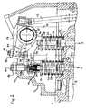
- Fig. 1 a detail of a 4-stroke reciprocating internal combustion engine is shown, the per cylinder 1 has at least one inlet valve (not shown) and two outlet valves 2, 3. 4, the installation space of the cylinder 1 with 5 is a piston working in the cylinder 1, with a 6 Cylinder head and designated 7 a cylinder cover.
- the outlet channels 8 of the cylinder 1 open into one or more exhaust manifolds and form with the latter part of the exhaust tract 9.
- a throttle device 10 is installed in the exhaust tract 9 as close as possible. This can, for example, by a throttle valve or a poppet valve or a Slider be formed. In most cases, a throttle is used.
- the throttle device 10 forms including its tax and / or regulatory bodies (on the next discussed in more detail below) a part of the engine dust brake device according to the invention and is used during engine braking operations to at least partially shut off the Exhaust tract and thereby caused upstream Aufstauung the exhaust gas.
- Another Part of the engine dust brake device is an engine-internal brake device 11 according to the invention Type, which is also discussed in more detail later.
- the inputs and Exhaust valves are controlled by a camshaft (not shown). Is this overhead, it acts directly on rocker arms. On the other hand, if it is lower, it is indirect via pushrods on the rocker arms.
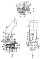
- Fig. 2 shows the version with below Camshaft in the area of the control of the two exhaust valves of a cylinder.
- Each of them is axially movable with its shaft 21 and 22 in the cylinder head 6 stored and by a closing spring 23 and 24, the one end on a cylinder head surface 25 and 26 and the other at one attached to the outlet valve stem 21 and 22 respectively Spring plate 27 and 28 is supported, with a certain biasing force F1 in the closing direction applied.
- Each of the two closing springs 23 and 24 can either by only one Spiral spring or two mutually coaxial coil springs be realized.
- each cylinder 1 associated with only one (2) of the two exhaust valves 2, 3, the other exhaust valve 3 is normally effective and operated, therefore also in conventional Way with the upper end of its shank on the bottom 29 of the valve bridge 20th supported.
- the one-outlet valve 2 associated with engine braking device 11 from a control piston 30, at which the outlet valve 2 with the upper End of his shaft 21 is supported.
- the control piston 30 is in a in the valve bridge 20th given blind bore 31 lickagearm axially movable guided and received by a supplied with pressure oil control pressure chamber 33 ago and possibly by an additional Control spring 32 in the direction of exhaust valve stem 21 pressed.
- the pressure oil supply to Control pressure chamber 33 via a in the rocker arm 13 and the bolt 18 with Abstweilkalotte 19 trained oil supply channel 34 and communicating with this Oil supply passage 35 in the valve bridge 20.
- In the valve bridge internal oil supply passage 35 is an oil built only in the direction of the control pressure chamber 33 permeable check valve 36.
- the pressure oil supply to the rocker arm 13 takes place from the outside either via a supply line in a channel in Kipphebellagerbolzen 15 and channels in the sliding bearing 16 or a supply line to the push rod 12 and a push rod internal channel, with which the rocker arm internal Oil supply channel 34 communicates.
- control pressure chamber 33 From the control pressure chamber 33 branches off a discharge channel 37, which at the top 38 of the Valve bridge 20 opens and its local outlet opening 39 by a simultaneously a stop for the valve bridge 20 forming counter holder 40 closed or for Pressure relief of the control pressure chamber 33 after lifting the valve bridge 20 can be released is.
- the biasing force F1 is the Closing spring 23 of that exhaust valve 2, which the engine-internal braking device 11 assigned is dimensioned such that during engine braking at throttle position befind another Throttle device 10 due to the accumulated in the exhaust gas in conjunction with the Exhaust counterpressure P2 occurring in this pressure pulsations an intermediate opening of the relevant outlet valve 2, and indeed - as shown in FIG. 9 - at the end the 1st clock (intake stroke) every 4-stroke cycle.
- this intermediate opening of the exhaust valve 2 is according to the invention control technology with the engine-internal engine brake device 11 automatically intervened in such a way that after the intermediate opening at the beginning of the 2.
- Exhaust counterpressure P2 reaches during engine braking when in the closed position Throttle device 10 its maximum.
- the control piston 30 of the engine-internal braking device 11 faces the front - to the exhaust valve 2 towards - a blind hole 41, with which he the upper end of the outlet valve stem 21st cap-like overlaps with game and is thus coupled to the exhaust valve 2.
- the control piston 30 is in the valve bridge internal blind bore 31 between two stops limited stroke movable. Here is the upper, the retracted home position defining Stop 42 in the case of the example of FIG. 3 to 5 by an annular Shoulder surface at the transition between two different diameter sections of the Blind bore 31 given, wherein the larger diameter portion of the control piston 30th receives and the smaller diameter portion forms the control pressure chamber 33 and also the control spring 32 receives laterally guided.
- control pressure spring 32 in This embodiment is taken centered in a rear blind hole 44 in the control piston 30 and supported there at the bottom 45. Changing is the control pressure spring 32 supported on the bottom 46 of the valve bridge internal blind bore 31. In the case of the example 6 to 8, however, the upper, the retracted basic position of the control piston predetermining stop 42 through the bottom 46 of the valve bridge internal blind bore educated. On the control piston 30, a coaxial pin 47 is arranged in this case on the back, with its rear end face 48 it is at the bottom 46 of the blind bore 31 to the plant comes.
- the discharge channel 37 is preferably centrally, so that the pin 47 also fulfills the additional function, namely that in every 4th motor cycle immediately after the start of the camshaft-controlled opening stroke movement of the valve bridge 20 and the concomitant lifting the same from the counter-holder 40 a pressure relief the control pressure chamber 33 causing cumshot of pressure oil through the discharge channel 37 is limited in quantity, because the discharge channel 37 through the pin 47 of immediately returning to its normal position control piston 30 from the inside again is closed. This limits the loss of oil in the control pressure space 33 and provides one therein high oil pressure safe.
- the control compression spring 32 is in this case at an annular Shoulder surface 49 supported on the control piston 30 and by the coaxial pin 47 centered.
- the lower, the widest extended position of the control piston predetermining stop 43rd is equal in both embodiments of FIG. 3 to 5 and FIG. 6 to 8 and z. B. realized by a transverse pin 50, which is pressed into a transverse bore 51 in the valve bridge 20 is laterally protrudes into the clear cross section of the blind hole 31 and there in a outer indentation 52 on the control piston 30 is immersed, the upper boundary wall as Stop 43 the extension stroke of the control piston 30 in cooperation with the transverse pin 50 limited.
- the anvil 40 for the valve bridge 20 is connected by a cylinder cover 7 z. B. by a lock nut fixed, adjustable with respect to their stop position stud 54th educated.
- the discharge port 37 which can be shut off or released on the outlet side is thus preferably by one of the blind bore 31 coaxial with the top 38 of the valve bridge 20 leading throttle bore formed, whose diameter is much smaller than that smallest cross-section of the oil supply channel 35 in the valve bridge.
- the check valve 36 has as a control member on a ball 55 and the associated valve seat is by a conical transition surface 56 between two diametrically different Oil supply passage sections 57, 58 formed, wherein the ball 55 in the larger diameter oil supply passage section 58 arranged there and their opening stroke by a stop 59th is limited.
- the cross section of the oil supply channel 34 in the rocker arm 13 is either the same, preferably but larger than that of the subsequent oil supply passage 35 in the valve bridge 20. Der smallest cross-section of the oil supply channel 35 is internally the valve bridge 20 in the region of Check valve 36, there in the annular gap around the ball 55 in the oil supply passage section 58th given. In general, the check valve 36 should be as close as possible to the control pressure chamber 33 be positioned towards.
- the effective biasing force F1 of the closing spring 23 of the exhaust valve 2 is greater than that Effective preload force of the internal control valve spring 32.
- the theoretical Background of the engine dust brake device according to the invention is at the end of the description specified.
- the throttle device should 10 in the exhaust tract 9, if possible in terms of flow in front of the turbine of the exhaust gas turbocharger be arranged.
- the volume of the throttle device should be 10 shut-off portion 61 of the exhaust tract 9 selected as low as possible, ie the throttle device 10 as possible close to the engine z. B. at the output of one or more merged Exhaust manifold and arranged spatially in front of the turbine of the exhaust gas turbocharger be.
- the control of the throttle device 10 can be realized as also shown schematically in FIG. 1.
- the throttle device 10 is formed there by a throttle valve, which is installed in the exhaust tract 9 and is rotatably or pivotably mounted there with its axis 62.
- a servomotor 63 for adjusting or adjusting the throttle valve 10 is a servomotor 63.
- This can be realized by an electric motor or a hydraulically or pneumatically actuable actuating cylinder.
- the servomotor 63 is realized by a pneumatically actuable actuating cylinder, which can be supplied with compressed air via a compressed air line 65 connected to a compressed air supply device 64.
- the servo motor 63 is associated with a power unit 66, which consists in the illustrated example of an electromagnetic shut-off / passage valve 67 and an electrical switching member 68 for actuating the latter.
- This power unit 66 receives its commands via a control line 69 from an electronic control and / or regulating unit 70.
- Designated at 71 is a pressure sensor which detects the exhaust-gas pressure in terms of flow in front of the throttle valve 10.
- a temperature sensor 72 may be provided, which detects the exhaust gas temperature in terms of flow in front of the throttle valve 10.
- the control and / or regulating unit 70 consists for example of an input and output peripherals, a microprocessor and data and program memories, which modules are linked together via a data bus system. In the data memories maps and operating data for the operation control of the internal combustion engine are stored both in the train operation and braking operation.
- the control and / or regulating unit 70 thus regulates the operation of the internal combustion engine by means of programs stored in the program memory on the basis of the maps and operating data. The latter can be done during engine braking operation either by an open-close adjustment of the throttle valve 10 or in the sense of a sensitive input or adjustment of the throttle valve 10.
- the control and / or regulating unit 70 gives its commands via the line 69 to the switching member 68, which is connected via switching lines 76, 77 with the shut-off / passage valve 67.
- the switching member 68 which is connected via switching lines 76, 77 with the shut-off / passage valve 67.
- the throttle device 10 is switched on or adjusted accordingly.
- this regulation of braking power can be integrated into an electronically controlled braking strategy which optimally coordinates the use of all the brakes available in the vehicle (service brakes, retarder, engine brake) ,
- the throttle apparatus 10 When an engine braking operation is initiated, the throttle apparatus 10 is controlled by commands of Control and / or regulating unit 70 brought into a closed position, so that upstream of the Throttle device 10 results in a pressure increase with corresponding exhaust back pressure.
- Exhaust valve intermediate opening is according to the invention control technology during braking operation automatically intervened.
- the exhaust valve 2 At the beginning of the first cycle (intake stroke), the exhaust valve 2 is in the closed position A.
- the control piston 30 of the engine-internal braking device 11 is in its blind bore 31st set to stop and acts as a mechanical buffer, passing through the closed Exhaust valve 2 is pressed in this retracted position.
- the exhaust gas pressure-induced intermediate opening of the Exhaust valve 2 with a valve lift A ⁇ B at the end of phase A1 is achieved.
- the control piston 30 Following the opening movement of the inter-opening exhaust valve 2 is the control piston 30 by the oil pressure in the control pressure chamber 33 and the force of possibly existing control spring 32 tracked and extreme in its stop-related Extended intercept position.
- the biasing force F1 of the closing spring 23 of the exhaust valve 2 is within the allowable Design range, which results from the Ventilretedynamik calculation, for the Operation of the engine dust brake device designed so that the exhaust valve 2 based on the given with closed throttle device 10 in the pent-up exhaust gas Exhaust back pressure safely interposed.
- F1 should not be too low, because otherwise the air flow and the exhaust gas back pressure drop, whereby the internal cooling of the Internal combustion engine in braking mode and the braking power would be lower.
- the boost pressure in braking mode usually equal to Atmospheric pressure
- the cylinder per has two exhaust valves, in engine braking operation a very high engine braking power achieve.
Landscapes
- Engineering & Computer Science (AREA)
- Mechanical Engineering (AREA)
- General Engineering & Computer Science (AREA)
- Valve Device For Special Equipments (AREA)
- Output Control And Ontrol Of Special Type Engine (AREA)
- Control Of Throttle Valves Provided In The Intake System Or In The Exhaust System (AREA)
- Exhaust Silencers (AREA)
- Valve-Gear Or Valve Arrangements (AREA)
- Braking Arrangements (AREA)
Abstract
Description
Die Erfindung betrifft eine Motorstaubremsvorrichtung einer 4-Takt-Hubkolbenbrennkraftmaschine
mit Merkmalen gemäß dem Oberbegriff des Anspruchs 1.The invention relates to a motor dust brake device of a 4-stroke reciprocating internal combustion engine
with features according to the preamble of
Die Erfindung geht aus von der EP 0736672 B1. Diese offenbart ein Verfahren zur Motorbremsung mit einer 4-Takt-Hubkolbenbrennkraftmaschine, die eine motorinterne, einem Auslassventil zugeordnete Bremsvorrichtung aufweist. Das diesbezügliche Auslassventil ist über einen entweder direkt oder über eine Stößelstange betätigbaren Kipphebel steuerbar. Die Teile der Bremsvorrichtung sind als entweder in den Kipphebel oder in den Bereich der Stößelstange integriert offenbart. Für einen mehr als zwei-ventiligen Motor wird jedoch kein Lösungsvorschlag angegeben.The invention is based on EP 0736672 B1. This discloses a method for engine braking with a 4-stroke reciprocating internal combustion engine, an internal engine, a Has outlet valve associated brake device. The relevant outlet valve is controllable via a rocker arm which can be actuated either directly or via a push rod. The parts of the braking device are considered either in the rocker arm or in the area of Pushrod integrated disclosed. For a more than two-valve engine but no Proposed solution.
Es ist daher Aufgabe der Erfindung, eine Motorstaubremsvorrichtung für eine 4-Takt-Hubkolbenbrennkraftmaschine mit je Zylinder wenigstens einem Einlassventil und zwei Auslassventilen zu schaffen, die es ermöglicht, ein Motorbremsverfahren ähnlich jenem der EP 0736672 B1 darzustellen.It is therefore an object of the invention to provide a motor dust brake device for a 4-stroke reciprocating internal combustion engine with each cylinder at least one inlet valve and two exhaust valves to provide an engine braking method similar to that of EP 0736672 B1.
Diese Aufgabe ist erfindungsgemäß mit einer Motorstaubremsvorrichtung gelöst, die die
kennzeichnenden Merkmale des Anspruchs 1 aufweist.This object is achieved with a motor dust brake device according to the invention, which
having characteristic features of
Dabei ist es ein wesentliches Kriterium der Erfindung, dass die motorinterne Bremsvorrichtung nicht beiden Auslassventilen je Zylinder zugeordnet ist, was aus Platzgründen schwierig zu realisieren wäre, sondern von vornherein dahingehend konzipiert wurde, dass sie nur in Verbindung mit einem der beiden Auslassventile je Zylinder wirksam wird, das andere Auslassventil dagegen normal bzw. auf herkömmliche Weise betätigbar ist.It is an essential criterion of the invention that the motor-internal braking device not assigned to both exhaust valves per cylinder, which is difficult for reasons of space would be realized, but was designed from the outset that they only in Connection with one of the two exhaust valves per cylinder is effective, the other exhaust valve on the other hand is normal or can be actuated in a conventional manner.
Diesem maßgeblichen Merkmal ordnen sich die übrigen Merkmale der Erfindung unter, weil sie auf das Wirksamwerden der motorinternen Bremsvorrichtung an dem nur einen Auslassventil abgestellt sind.This significant feature arrange the other features of the invention, because on the effectiveness of the engine-internal braking device on the only one exhaust valve are turned off.
Im einzelnen weist die motorinterne Bremsvorrichtung einen Steuerkolben auf, an dem sich
das Auslassventil mit seinem Schaft abstützt. Der Steuerkolben ist in einer Sackbohrung der
Ventilbrücke axial beweglich geführt aufgenommen und von einem mit Drucköl versorgten
Steuerdruckraum her sowie eventuell durch eine zusätzliche Steuerdruckfeder in Richtung
Auslassventil-Schaft gedrückt. Die Druckölzufuhr zum Steuerdruckraum erfolgt über einen
mit einem kipphebelinternen Ölzufuhrkanal kommunizierenden ventilbrückeninternen Ölzufuhrkanal,
in welch letzteren ein nur in Richtung Steuerdruckraum durchlässiges Rückschlagventil
eingebaut ist. Vom Steuerdruckraum geht ein Entlastungskanal ab, der an der
Oberseite der Ventilbrücke ausmündet und dessen Austrittsöffnung durch einen gleichzeitig
einen Anschlag für die Ventilbrücke bildenden Gegenhalter verschließbar bzw. für Druckentlastung
des Steuerdruckraumes nach Abheben der Ventilbrücke freigebbar ist. Des weiteren
ist die Vorspannkraft der diesem Auslassventil zugeordneten Schließfeder derart bemessen,
dass sich während des Motorbremsens bei in Drosselstellung befindlicher Drosselvorrichtung
aufgrund des im aufgestauten Abgas in Verbindung mit den darin wirkenden Druckpulsationen
auftretenden Abgasgegendruckes ein Zwischenöffnen des Auslassventils ergibt. In dieses
Zwischenöffnen ist während jedes 4-Takt-Motorzyklus mit der motorinternen Bremsvorrichtung
steuerungstechnisch automatisch derart eingreifbar, dass das nach Zwischenöffnung
anfangs des 2-Taktes zum Schließen neigende Auslassventil durch den öldruckbedingt
und eventuell auch steuerdruckfederbeaufschlagt nachrückenden Steuerkolben abgefangen
und während des 2. und 3. Taktes am Schließen gehindert sowie bis zu seiner anfangs des
4. Taktes erfolgenden nockenwellengesteuerten Öffnung teilweise offen gehalten wird. Der
Abgasgegendruck hat bei in Schließposition befindlicher Drosselvorrichtung sein Maximum,
ist aber gegebenenfalls durch gesteuerte und/oder geregelte Öffnung der Drosselvorrichtung
erniedrigbar, um eine Reduzierung der Motorbremsleistung und/oder der Temperatur motorinterner
Bauteile zwecks Vermeidung von deren Überhitzung zu bewirken. Der Querschnitt
der Ölzufuhrkanäle im Kipphebel und der Ventilbrücke sowie der Druck des dem Steuerdruckraum
zugeführten Öles sind derart aufeinander abgestimmt, dass während des besagten
Zwischenöffnens des Auslassventils der sich aufgrund des nachrückenden Steuerkolbens
vergrößernde Steuerdruckraum zumindest nahezu vollständig mit Drucköl füllen kann
und daher dann am Ende des Zwischenöffnungshubes ein Halten des Auslassventils in abgefangener
Teilöffnungsposition möglich ist.In detail, the engine-internal brake device has a control piston on which
the exhaust valve is supported by its shaft. The spool is in a blind hole the
Valve bridge axially movably recorded and supplied by a pressurized oil
Control pressure chamber ago and possibly by an additional control spring in the direction
Exhaust valve stem pressed. The pressure oil supply to the control pressure chamber via a
valve bridge internal oil supply channel communicating with a toggle internal oil supply channel,
in which latter one only in the direction of control pressure chamber permeable check valve
is installed. From the control pressure chamber goes from a discharge channel, which at the
Top of the valve bridge opens and its outlet opening through a simultaneously
a stop for the valve bridge forming counter holder closed or for pressure relief
of the control pressure chamber is releasable after lifting the valve bridge. Furthermore
the biasing force of the closing spring associated with this outlet valve is dimensioned such that
during engine braking, when the throttle device is in throttle position
due to the accumulated exhaust gas in conjunction with the pressure pulsations acting therein
occurring exhaust back pressure results in an intermediate opening of the exhaust valve. In this
Intermediate opening is during each 4-stroke engine cycle with the engine-internal brake device
Control technology automatically engageable such that after intermediate opening
At the beginning of the 2-stroke closing valve inclined by the oil pressure
and possibly also tax Druckfederbeaufschlagt nachrückenden control piston intercepted
and prevented from closing during the 2nd and 3rd bars, and until its
Ersichtlicherweise ist diese erfindungsgemäße Motorstaubremsvorrichtung mit einigen wenigen, billig herstellbaren Bauteilen realisierbar. Die Motorbremsung erfolgt automatisch selbststeuernd ohne äußeres Einwirken lediglich in Abhängigkeit von Abgasgegendruck im abgesperrten Abgastrakt und erbringt nachweislich eine sehr hohe Motorbremsleistung.Evidently, this engine dust brake device according to the invention is equipped with a few, cheap manufacturable components feasible. The engine braking is automatic self-controlling without external influences only as a function of exhaust back pressure in shut off exhaust tract and demonstrably provides a very high engine braking power.
Nachfolgend ist die erfindungsgemäße Lösung anhand der Zeichnung noch näher erläutert. In der Zeichnung zeigen:
- Fig. 1
- schematisch eine 4-Takt-Hubkolbenbrennkraftmaschine und deren Abgastrakt mit Drosseleinrichtung sowie einem Prinzipbild einer möglichen Steuerung für letztere,
- Fig. 2
- einen Teilschnitt durch eine vier-ventilige 4-Takt-Hubkolbenbrennkraftmaschine im Bereich der Auslassventile und deren Steuerung, mit einem ersten Ausführungsbeispiel der erfindungsgemäßen motorinternen Bremsvorrichtung,
- Fig. 3
- die Ventilbrücke und weitere Teile der motorinternen Bremsvorrichtung gemäß Fig. 2 in Einzeldarstellung und im Schnitt,
- Fig. 4
- eine Draufsicht auf die Ventilbrücke gemäß Fig. 2 und 3,
- Fig. 5
- einen vergrößerten Ausschnitt aus der Darstellung von Fig. 3,
- Fig. 6
- ein weiteres Ausführungsbeispiel einer Ventilbrücke und weiterer Teile der motorinternen Bremsvorrichtung in Einzeldarstellung und im Schnitt,
- Fig. 7
- eine Draufsicht auf die Ventilbrücke gemäß Fig. 5,
- Fig. 8
- einen vergrößerten Ausschnitt aus der Darstellung von Fig. 6, und
- Fig. 9
- ein Diagramm, aus dem der Hubverlauf des Auslassventils, dem die erfindungsgemäße motorinterne Bremsvorrichtung zugeordnet ist, während des Bremsbetriebes hervorgeht.
- Fig. 1
- schematically a 4-stroke reciprocating internal combustion engine and its exhaust system with throttle device and a schematic diagram of a possible control for the latter,
- Fig. 2
- a partial section through a four-valve four-stroke reciprocating internal combustion engine in the region of the exhaust valves and their control, with a first embodiment of the engine-internal braking device according to the invention,
- Fig. 3
- the valve bridge and other parts of the engine-internal braking device according to FIG. 2 in individual representation and in section,
- Fig. 4
- a top view of the valve bridge of FIG. 2 and 3,
- Fig. 5
- an enlarged detail of the illustration of Fig. 3,
- Fig. 6
- a further embodiment of a valve bridge and other parts of the engine-internal braking device in a single representation and in section,
- Fig. 7
- a top view of the valve bridge of FIG. 5,
- Fig. 8
- an enlarged section of the illustration of Fig. 6, and
- Fig. 9
- a diagram from which the stroke of the exhaust valve, which is associated with the engine-internal brake device according to the invention, during the braking operation emerges.
In Fig. 1 ist ausschnittsweise eine 4-Takt-Hubkolbenbrennkraftmaschine gezeigt, die je Zylinder
1 wenigstens ein Einlassventil (nicht dargestellt) und zwei Auslassventile 2, 3 aufweist.
Mit 4 ist der Bauraum des Zylinders 1 mit 5 ein im Zylinder 1 arbeitender Kolben, mit 6 ein
Zylinderkopf und mit 7 ein Zylinderdeckel bezeichnet. Die Auslasskanäle 8 der Zylinder 1
münden in einen oder mehrere Auslasskrümmer und bilden mit letzterem einen Teil des Abgastraktes
9. In den Abgastrakt 9 ist möglichst motornah eine Drosselvorrichtung 10 eingebaut.
Diese kann zum Beispiel durch eine Drosselklappe oder ein Tellerventil oder einen
Schieber gebildet sein. In den meisten Fällen wird eine Drosselklappe verwendet. Die Drosselvorrichtung
10 bildet einschließlich ihrer Steuer- und/oder Regelorgane (auf die weiter
hinten noch näher eingegangen ist) ein Teil der erfindungsgemäßen Motorstaubremsvorrichtung
und dient während Motorbremsvorgängen zur zumindest partiellen Absperrung des
Abgastraktes und einer hierdurch stromauf hervorgerufenen Aufstauung des Abgases. Weiterer
Teil der Motorstaubremsvorrichtung ist eine motorinterne Bremsvorrichtung 11 erfindungsgemäßer
Bauart, auf die ebenfalls weiter hinten näher eingegangen ist. Die Ein- und
Auslassventile sind von einer (nicht dargestellten) Nockenwelle her steuerbar. Ist diese
obenliegend, wirkt sie direkt auf Kipphebel ein. Ist sie dagegen untenliegend, wirkt sie indirekt
über Stößelstangen auf die Kipphebel ein. Fig. 2 zeigt die Version mit untenliegender
Nockenwelle im Bereich der Steuerung der beiden Auslassventile eines Zylinders. Die dargestellte,
an der Nockenwelle abgestützte Stößelstange 12 wirkt auf einen Kipphebel 13, der
am Zylinderkopf 6 in einem Lagerbock 14 auf einer Lagerachse 15 mit Gleitlager 16 drehbar
gelagert ist. Der Kipphebel 13 wiederum wirkt über einen einstellbaren und z. B. durch eine
Mutter 17 gekonterten Schraubenbolzen 18 mit einer an seinem freien Ende kugelgelenkig
angelenkten Stützkalotte 19 auf eine Ventilbrücke 20 ein. Diese Ventilbrücke 20 dient zur
Steuerung der beiden achsparallel zueinander angeordneten Auslassventile 2, 3 eines Zylinders
1. Jedes derselben ist mit seinem Schaft 21 bzw. 22 im Zylinderkopf 6 axial beweglich
gelagert und durch eine Schließfeder 23 bzw. 24, die sich einenendes an einer Zylinderkopffläche
25 bzw. 26 und andernendes an einem am Auslassventilschaft 21 bzw. 22 befestigten
Federteller 27 bzw. 28 abstützt, mit einer bestimmten Vorspannkraft F1 in Schließrichtung
beaufschlagt. Jede der beiden Schließfedern 23 bzw. 24 kann dabei entweder durch nur eine
Spiralfeder oder zwei zueinander koaxiale Spiralfedern realisiert sein.In Fig. 1 a detail of a 4-stroke reciprocating internal combustion engine is shown, the per
Einem erfindungsgemäßen Kriterium entsprechend ist die motorinterne Bremsvorrichtung 11
je Zylinder 1 nur einem (2) der beiden Auslassventile 2, 3 zugeordnet, das andere Auslassventil
3 ist normal bzw. herkömmlich wirksam und betätigt, demzufolge auch in herkömmlicher
Weise mit dem oberen Ende seines Schaftes an der Unterseite 29 der Ventilbrücke 20
abgestützt.According to a criterion of the invention, the engine-
Die dem einen Auslassventil 2 zugeordnete motorinterne Bremsvorrichtung 11 besteht erfindungsgemäß
aus einem Steuerkolben 30, an dem sich das Auslassventil 2 mit dem oberen
Ende seines Schaftes 21 abstützt. Der Steuerkolben 30 ist in einer in der Ventilbrücke 20
gegebenen Sackbohrung 31 leckagearm axial beweglich geführt aufgenommen und von einem
mit Drucköl versorgten Steuerdruckraum 33 her sowie eventuell durch eine zusätzliche
Steuerdruckfeder 32 in Richtung Auslassventil-Schaft 21 gedrückt. Die Druckölzufuhr zum
Steuerdruckraum 33 erfolgt über einen im Kipphebel 13 und dessen Schraubenbolzen 18 mit
Abstützkalotte 19 ausgebildeten Ölzufuhrkanal 34 und einen mit diesem kommunizierenden
Ölzufuhrkanal 35 in der Ventilbrücke 20. In den ventilbrückeninternen Ölzufuhrkanal 35 ist
ein Öl nur in Richtung des Steuerdruckraums 33 durchlässiges Rückschlagventil 36 eingebaut.
Die Druckölzufuhr zum Kipphebel 13 erfolgt von außen her entweder über eine Zuleitung
in einen Kanal im Kipphebellagerbolzen 15 und Kanäle im Gleitlager 16 oder eine Zuleitung
zur Stößelstange 12 sowie einen stößelstangeninternen Kanal, mit dem der kipphebelinterne
Ölzufuhrkanal 34 kommuniziert.The one-
Vom Steuerdruckraum 33 zweigt ein Entlastungskanal 37 ab, der an der Oberseite 38 der
Ventilbrücke 20 ausmündet und dessen dortige Austrittsöffnung 39 durch einen gleichzeitig
einen Anschlag für die Ventilbrücke 20 bildenden Gegenhalter 40 verschließbar bzw. für
Druckentlastung des Steuerdruckraumes 33 nach Abheben der Ventilbrücke 20 freigebbar
ist.From the
Unter normalen Betriebsbedingungen des Verbrennungsmotors, also wenn kein Motorbremsen
initiiert ist, werden die beiden Auslassventile 2, 3 eines Zylinders 1 über die Ventilbrücke
20 synchron betätigt, das heißt, innerhalb jedes 4-Takt-Zyklus zum Ende des 3. Taktes
(Expansionstakt) geöffnet, während des 4. Taktes (Ausschubtakt) offen gehalten und dann
zum Beginn des nächsten 1. Taktes (Ansaugtakt) hin wieder geschlossen.Under normal operating conditions of the internal combustion engine, so if no engine braking
is initiated, the two
Bei der erfindungsgemäßen Motorstaubremsvorrichtung ist die Vorspannkraft F1 der
Schließfeder 23 jenes Auslassventils 2, dem die motorinterne Bremsvorrichtung 11 zugeordnet
ist, derart bemessen, dass sich während des Motorbremsens bei in Drosselstellung befindlicher
Drosselvorrichtung 10 aufgrund des im aufgestauten Abgas in Verbindung mit den
darin wirkenden Druckpulsationen auftretenden Abgasgegendrucks P2 ein Zwischenöffnen
des betreffenden Auslassventils 2 einstellt, und zwar - wie aus Fig. 9 ersichtlich - am Ende
des 1. Taktes (Ansaugtakt) jedes 4-Takt-Zyklus. In dieses Zwischenöffnen des Auslassventils
2 wird mit der motorinternen Motorbremsvorrichtung 11 erfindungsgemäß steuerungstechnisch
automatisch derart eingegriffen, dass das nach Zwischenöffnung anfangs des 2.
Taktes (Kompressionstakt) zum Schließen neigende Auslassventil 2 abgefangen und während
des 2. und 3. Taktes am Schließen gehindert sowie bis zu seiner anfangs des 4. Taktes
erfolgenden nockenwellengesteuerten Öffnung teilweise offen gehalten wird. Auf die exakten
Abläufe auch innerhalb der motorinternen Motorbremsvorrichtung 11 ist weiter hinten noch
näher eingegangen. In the engine dust brake device according to the invention, the biasing force F1 is the
Der Abgasgegendruck P2 erreicht während des Motorbremsens bei in Schließposition befindlicher
Drosselvorrichtung 10 sein Maximum. Es kann jedoch durchaus zweckmäßig und
sinnvoll sein, den während des Motorbremsens wirksamen Abgasgegendruck P2 durch gesteuerte
und/oder geregelte Öffnung der Drosselvorrichtung 10 weg von ihrer Schließstellung
zu verkleinern, um eine gezielte Reduzierung der Motorbremsleistung und/oder der Temperatur
motorinterner Bauteile zwecks Vermeidung von deren Überhitzung und/oder Verkokung
herbeizuführen.Exhaust counterpressure P2 reaches during engine braking when in the closed
Außerdem sind innerhalb der motorinternen Bremsvorrichtung 11 erfindungsgemäß der
Querschnitt der Ölzufuhrkanäle 34, 35 und der darin sowie im Steuerdruckraum 33 wirksame
Öldruck derart aufeinander abgestimmt, dass während des besagten Zwischenöffnens des
Auslassventils 2 im Motorbremsbetrieb der sich aufgrund des nachrückenden Steuerkolbens
30 volumenmäßig vergrößernde Steuerdruckraum 33 zumindest nahezu vollständig mit
Drucköl füllbar ist und solchermaßen dann gegen Ende des Zwischenöffnungshubes ein
Halten des Auslassventils 2 in abgefangener Teilöffnungsposition über den vom Steuerdruckraum
33 her ölseitig verblockten Steuerkolben 30 gewährleistet ist.In addition, within the engine-
Nachfolgend ist auf Details und Ausführungsvarianten der erfindungsgemäßen Lösung näher eingegangen.The following is closer to details and embodiments of the inventive solution received.
Der Steuerkolben 30 der motorinternen Bremsvorrichtung 11 weist vorne - zum Auslassventil
2 hin - ein Sackloch 41 auf, mit dem er das obere Ende des Auslassventil-Schaftes 21
kappenartig mit Spiel übergreift und solchermaßen mit dem Auslassventil 2 gekoppelt ist.
Der Steuerkolben 30 ist in der ventilbrückeninternen Sackbohrung 31 zwischen zwei Anschlägen
hubbegrenzt bewegbar. Dabei ist der obere, die eingefahrene Grundposition definierende
Anschlag 42 im Fall des Beispiels gemäß Fig. 3 bis 5 durch eine ringförmige
Schulterfläche am Übergang zwischen zwei durchmesserunterschiedlichen Abschnitten der
Sackbohrung 31 gegeben, wobei der durchmessergrößere Abschnitt den Steuerkolben 30
aufnimmt und der durchmesserkleinere Abschnitt den Steuerdruckraum 33 bildet und außerdem
die Steuerdruckfeder 32 seitlich geführt aufnimmt. Dabei ist die Steuerdruckfeder 32 in
diesem Ausführungsbeispiel in einem hinteren Sackloch 44 im Steuerkolben 30 zentriert aufgenommen
und dort an dessen Boden 45 abgestützt. Andernendes ist die Steuerdruckfeder
32 am Boden 46 der ventilbrückeninternen Sackbohrung 31 abgestützt. Im Fall des Beispiels
gemäß Fig. 6 bis 8 dagegen ist der obere, die eingefahrene Grundposition des Steuerkolbens
vorgebende Anschlag 42 durch den Boden 46 der ventilbrückeninternen Sackbohrung
gebildet. Am Steuerkolben 30 ist in diesem Fall rückseitig ein koaxialer Zapfen 47 angeordnet,
mit dessen hinterer Stirnfläche 48 er am Boden 46 der Sackbohrung 31 zur Anlage
kommt. Von dort geht der Entlastungskanal 37 vorzugsweise mittig ab, so dass der Zapfen
47 auch noch die Zusatzfunktion erfüllt, nämlich dass das in jedem 4. Motor-Takt unmittelbar
nach Beginn der nockenwellengesteuerten Öffnungshubbewegung der Ventilbrücke 20
und dem damit einhergehenden Abheben derselben vom Gegenhalter 40 eine Druckentlastung
des Steuerdruckraumes 33 bewirkende Abspritzen von Drucköl über den Entlastungskanal
37 mengenmäßig begrenzt wird, weil der Entlastungskanal 37 durch den Zapfen 47
des sofort in seine Grundstellung zurückkehrenden Steuerkolbens 30 von innen her wieder
verschlossen wird. Dies begrenzt den Ölverlust im Steuerdruckraum 33 und stellt einen darin
hoch bleibenden Öldruck sicher. Die Steuerdruckfeder 32 ist in diesem Fall an einer ringförmigen
Schulterfläche 49 am Steuerkolben 30 abgestützt und durch dessen koaxialen Zapfen
47 zentriert.The
Der untere, die weitest ausgefahrene Position des Steuerkolbens vorgebende Anschlag 43
ist in beiden Ausführungsbeispielen gemäß Fig. 3 bis 5 und Fig. 6 bis 8 gleich und z. B.
durch einen Querstift 50 realisiert, der in eine Querbohrung 51 in der Ventilbrücke 20 eingepresst
ist, in den lichten Querschnitt des Sackloches 31 seitlich hineinragt und dort in eine
äußere Einbuchtung 52 am Steuerkolben 30 eintaucht, deren obere Begrenzungswand als
Anschlag 43 den Ausfahrhub des Steuerkolbens 30 im Zusammenwirken mit dem Querstift
50 begrenzt.The lower, the widest extended position of the control piston predetermining stop 43rd
is equal in both embodiments of FIG. 3 to 5 and FIG. 6 to 8 and z. B.
realized by a
Der Gegenhalter 40 für die Ventilbrücke 20 ist durch eine im Zylinderdeckel 7 z. B. durch
eine Kontermutter fixierte, hinsichtlich ihrer Anschlagposition einstellbare Stiftschraube 54
gebildet. Der hierdurch austrittsseitig absperrbare oder freigebbare Entlastungskanal 37 ist
vorzugsweise durch eine von der Sackbohrung 31 koaxial zur Oberseite 38 der Ventilbrücke
20 führende Drosselbohrung gebildet, deren Durchmesser wesentlich kleiner als der
kleinste Querschnitt des Ölzufuhrkanals 35 in der Ventilbrücke ist.The
Das Rückschlagventil 36 weist als Steuerorgan eine Kugel 55 auf und der zugehörige Ventilsitz
ist durch eine kegelige Übergangsfläche 56 zwischen zwei durchmesserverschiedenen
Ölzufuhrkanalabschnitten 57, 58 gebildet, wobei die Kugel 55 im durchmessergrößeren ÖIzufuhrkanal-Abschnitt
58 angeordnet und dort deren Öffnungshub durch einen Anschlag 59
begrenzt ist. Zur Hubbegrenzung der Rückschlagventil-Kugel 55 ist z. B. ein den Ölzufuhrkanal-Abschnitt
58 quer durchsetzender, in eine Querbohrung 60 in der Ventilbrücke eingepresster
Anschlagstift vorgesehen.The
Der Querschnitt des Ölzufuhrkanals 34 im Kipphebel 13 ist entweder gleich, vorzugsweise
jedoch größer als jener des anschließenden Ölzufuhrkanals 35 in der Ventilbrücke 20. Der
kleinste Querschnitt des Ölzufuhrkanals 35 ist intern der Ventilbrücke 20 im Bereich des
Rückschlagventils 36, dort im Ringspalt um dessen Kugel 55 im Ölzufuhrkanal-Abschnitt 58
gegeben. Generell sollte das Rückschlagventil 36 so nah wie möglich zum Steuerdruckraum
33 hin positioniert sein.The cross section of the
Die wirksame Vorspannkraft F1 der Schließfeder 23 des Auslassventils 2 ist größer als die
wirksame Vorspannkraft der ventilbrückeninternen Steuerdruckfeder 32. Der theoretische
Hintergrund der erfindungsgemäßen Motorstaubremsvorrichtung ist am Ende der Beschreibung
angegeben.The effective biasing force F1 of the
Generell sind die Komponenten der motorinternen Bremsvorrichtung 11 und der Druck des
dem Steuerdruckraum 33 zugeführten Öles so ausgelegt, dass das Auslassventil 2 während
des Motorbremsens nach seinem abgasgegendruckbewirkten Zwischenöffnen bis in eine
Öffnungsposition B (siehe Fig. 9) in einer Position C (siehe Fig. 9) abfangbar und haltbar ist,
deren Abstand zur Schließposition des Auslassventils etwa 1/5 bis 1/20 des vollen Auslassventilhubes
hmax=A→D (siehe Fig. 9) beträgt.In general, the components of the engine-
Wenn die Brennkraftmaschine über einen Abgasturbolader verfügt, sollte die Drosselvorrichtung
10 im Abgastrakt 9 nach Möglichkeit strömungsmäßig vor der Turbine des Abgasturboladers
angeordnet sein. Generell sollte das Volumen des mittels der Drosselvorrichtung
10 absperrbaren Abschnitts 61 des Abgastraktes 9 so gering wie möglich gewählt, also
die Drosselvorrichtung 10 möglichst motornah z. B. am Ausgang eines oder mehrerer zusammengeführter
Abgaskrümmer und räumlich vor der Turbine des Abgasturboladers angeordnet
sein.If the internal combustion engine has an exhaust gas turbocharger, the throttle device should
10 in the
Die Steuerung der Drosselvorrichtung 10 kann wie ebenfalls schematisch aus Fig. 1 ersichtlich
realisiert sein. Die Drosselvorrichtung 10 ist dort durch eine Drosselklappe gebildet, die
in den Abgastrakt 9 eingebaut und dort mit ihrer Achse 62 dreh- bzw. schwenkbar gelagert
ist. Zur Ein- bzw. Verstellung der Drosselklappe 10 dient ein Stellmotor 63. Dieser kann
durch einen Elektromotor oder einen hydraulisch oder pneumatisch betätigbaren Stellzylinder
realisiert sein. Im dargestellten Beispiel ist der Stellmotor 63 durch einen pneumatisch
betätigbaren Stellzylinder realisiert, der über eine an einer Druckluftversorgungseinrichtung
64 angeschlossene Druckluftleitung 65 mit Druckluft versorgbar ist. Dem Stellmotor 63
ist ein Leistungsteil 66 zugeordnet, das im dargestellten Beispiel aus einem elektromagnetischen
Absperr-/Durchlassventil 67 und einem elektrischen Schaltorgan 68 für Betätigung des
letzteren besteht. Dieses Leistungsteil 66 erhält seine Befehle über eine Steuerleitung 69
von einer elektronischen Steuer- und/oder Regeleinheit 70. Mit 71 ist ein Drucksensor bezeichnet,
der den Abgasdruck strömungsmäßig vor der Drosselklappe 10 erfasst. Anstelle
des Drucksensors 71 oder auch zusätzlich zu diesem kann ein Temperatursensor 72 vorgesehen
sein, der die Abgastemperatur strömungsmäßig vor der Drosselklappe 10 erfasst.
Diese Druck- und/oder Temperaturmesssignale, gegebenenfalls auch Drehzahlsignale nM
der Brennkraftmaschine und Temperaturmesssignale tB von temperaturmäßig überwachten
motorinternen Bauteilen wie Einspritzdüsen, werden über Signalleitungen 73, 74, 75 der
Steuer- und/oder Regeleinheit 70 zugeführt und von dieser als Basis für eine Betätigung der
Drosselklappe 10 herangezogen. Die Steuer- und/oder Regeleinheit 70 besteht beispielsweise
aus einer Ein- und Ausgabeperipherie, einem Mikroprozessor sowie Daten- und Programmspeichern,
welche Baugruppen über ein Datenbussystem miteinander verknüpft sind.
In den Datenspeichern sind Kennfelder und Betriebsdaten für die Betriebssteuerung der
Brennkraftmaschine sowohl im Zugbetrieb als auch Bremsbetrieb abgelegt. Die Steuerund/oder
Regeleinheit 70 regelt somit per im Programmspeicher abgespeichertem Programm
anhand der Kennfelder und Betriebsdaten den Betrieb der Brennkraftmaschine.
Letzteres kann während des Motorbremsbetriebes entweder durch eine Auf-Zu-Einstellung
der Drosselklappe 10 oder im Sinne einer feinfühligen Ein- bzw. Verstellung der Drosselklappe
10 geschehen. Die Steuer- und/oder Regeleinheit 70 gibt ihre Befehle über die Leitung
69 an das Schaltorgan 68, das über Schaltleitungen 76, 77 mit dem Absperr-/Durchlassventil
67 verbunden ist. Um während eines Motorbremsbetriebes eine gegenüber der
maximal möglichen geringere Bremsleistung zu erzeugen oder einer Überhitzung motorinterner
Bauteile entgegenzuwirken bzw. vorzubeugen, kann solchermaßen z. B. in Abhängigkeit
von datenmäßig vorgegebenen Zeitintervallen oder von gemessenen Bauteiltemperaturen
und/oder sonstigen Vorgaben, z. B. aus dem Betrieb des Fahrzeugs, das den Motor enthält,
die Drosselvorrichtung 10 entsprechend ein- bzw. verstellt werden. Diese Regelung der
Bremsleistung kann im Falle einer Brennkraftmaschine, die in ein Kraftfahrzeug, insbesondere
Nutzfahrzeug wie Lastkraftwagen oder Omnibus, eingebaut ist, in eine elektronisch geregelte
Bremsstrategie eingebunden sein, die den Einsatz aller im Fahrzeug verfügbaren
Bremsen (Betriebsbremsen, Retarder, Motorbremse) optimal koordiniert. The control of the
Nachstehend ist auf das Zusammenwirken der Teile der erfindungsgemäßen Motorstaubremsvorrichtung während eines Motorbremsbetriebes näher eingegangen.The following is on the interaction of the parts of the engine dust brake device according to the invention during an engine braking operation.
Wenn ein Motorbremsvorgang initiiert ist, wird die Drosselvorrichtung 10 durch Befehle der
Steuer- und/oder Regeleinheit 70 in eine Schließposition gebracht, so dass sich stromauf der
Drosselvorrichtung 10 ein Druckanstieg mit entsprechendem Abgasgegendruck ergibt. Die
beim Ausschieben von Abgas benachbarter Zylinder 1 entstehenden Druckwellen überlagern
sich dabei dem stationären Abgasgegendruck und bewirken infolge der positiven Druckdifferenz
ein Zwischenöffnen jedes einer motorinternen Bremsvorrichtung 11 zugeordneten Auslassventils
2 - siehe Phase A1 im Diagramm von Fig. 9 -, die sich am Ende des 1. Taktes
(Ansaugtakt) einstellt. In dieses unabhängig von der Nockenwellensteuerung erfolgende
Auslassventil-Zwischenöffnen wird während des Bremsbetriebes erfindungsgemäß steuerungstechnisch
automatisch eingegriffen. Dabei wird das nach Zwischenöffnung unter der
Einwirkung seiner Schließfeder 23 wieder zum Schließen neigende Auslassventil 2 zwangsweise
durch die zugeordnete motorinterne Bremsvorrichtung 11 abgefangen und dann mittels
dieser über den gesamten Kompressionstakt sowie Expansionstakt in teilgeöffneter Abfangposition
gehalten - siehe Phase A2 im Diagramm gemäß Fig. 9. Dabei laufen in der
motorinternen Bremsvorrichtung folgende Vorgänge ab.When an engine braking operation is initiated, the
Am Anfang des 1. Taktes (Ansaugtakt) befindet sich das Auslassventil 2 in Schließstellung
A. Der Steuerkolben 30 der motorinternen Bremsvorrichtung 11 ist in seiner Sackbohrung 31
auf Anschlag gesetzt und wirkt als mechanischer Puffer, wobei er durch das geschlossene
Auslassventil 2 in diese eingefahrene Position gedrückt ist.At the beginning of the first cycle (intake stroke), the
Gegen Ende des 1. Taktes erfolgt dann das abgasgegendruckbewirkte Zwischenöffnen des
Auslassventils 2 mit einem Ventilhub A→B, der am Ende der Phase A1 (siehe Diagramm
Fig. 9) erreicht wird. Der Öffnungsbewegung des zwischenöffnenden Auslassventils 2 folgend
wird der Steuerkolben 30 durch den Öldruck im Steuerdruckraum 33 und die Kraft der
eventuell vorhandenen Steuerdruckfeder 32 nachgeführt und in seine anschlagbedingt äußerste
Abfangposition ausgefahren. Einher geht mit diesem Ausfahren des Steuerkolbens 30
eine volumenmäßige Vergrößerung des Steuerdruckraumes 33 und dessen sofortiges Auffüllen
mit Drucköl über die Ölzufuhrkanäle 34, 35, wobei nach vollständiger Auffüllung des
Steuerdruckraumes 33 - wegen des sperrenden Rückschlagventils 36 und des durch den
Gegenhalter 40 abgesperrten Entlastungskanals 37 - der Steuerkolben 30 in seiner ausgefahrenen
Abfangstellung hydraulisch in der Ventilbrücke 20 verblockt ist. Beim Zwischenöffnen
eilt das Auslassventil 2 dem Hub des Steuerkolbens 30 mit größerem Hub voraus. Beim
Übergang von Phase A1 nach Phase A2 (siehe Diagramm Fig. 9) bewegt sich das Auslassventil
2 wieder in Schließrichtung, wird dann aber schon nach kurzem Rückweg B→C zu
Beginn des 2. Taktes (Kompressionstakt) durch den hydraulisch in der Ventilbrücke verblockten
Steuerkolben 30 abgefangen. Diese Abfangposition bleibt während der gesamten
Phase A2, also über den gesamten restlichen 2. Takt (Kompressionstakt) und folgenden 3.
Takt (Expansionstakt) erhalten.Towards the end of the first cycle, the exhaust gas pressure-induced intermediate opening of the
Erst dann, wenn am Ende des 3. Taktes (Expansionstakt) die nockenwellenseitige Steuerung
des Auslassventils 2 über den zugehörigen Steuernocken an der Nockenwelle, gegebenenfalls
die Stößelstange 12, den Kipphebel 13 und die Ventilbrücke 20 wieder wirksam
wird, erfolgt eine Aufhebung dieser vorherigen hydraulischen Verblockung des Steuerkolbens
30, denn sobald die Ventilbrücke 20 in Richtung "Auslassventil öffnen" bewegt wird,
hebt sie vom Gegenhalter 40 ab. Dadurch wird der Entlastungskanal 37 freigegeben und
Drucköl kann durch diesen nun aus dem hydraulisch nicht mehr verblockten Steuerdruckraum
33 in den Bereich des Zylinderdeckels 7 ausströmen, was auch durch den unter Einwirkung
des durch seine Schließfeder 23 in Schließrichtung bewegten Auslassventils 2 in
Richtung seiner eingefahrenen Grundstellung gedrückten Steuerkolben 30 unterstützt wird.Only then, when at the end of the 3rd clock (expansion stroke), the camshaft side control
the
Sobald der Steuerkolben 30 wieder voll in die ventilbrückeninterne Sackbohrung 31 auf Anschlag
eingedrückt ist, wirkt er wieder nur als rein mechanischer Puffer an der Ventilbrücke
20, über die in Phase A3 (siehe Diagramm Fig. 9) während des 4. Taktes (Ausschubtakt)
beim Motorbremsen das Öffnen des Auslassventils 2 dann - synchron zum zweiten Auslassventil
3 - bis zum vollen Auslassventilhub D, dessen bzw. deren Halten und Wieder-Schließen
gesteuert durch den entsprechenden Nocken an der Nockenwelle und über den
Kipphebel 13 erfolgt. Am Ende des 4. Taktes (Ausschubtakt) nimmt die Ventilbrücke 20 während
des Motorbremsens wieder ihre in Fig. 1 und 2 gezeigte Position ein, aus der heraus
der nächste in gleicher Weise wie vorher beschrieben ablaufende Bremszyklus abläuft.As soon as the
Nachfolgend noch einige Angaben zum theoretischen Hintergrund der erfindungsgemäßen Motorstaubremsvorrichtung:Below some information on the theoretical background of the invention Engine air brake device:
Wie bereits erwähnt, wird das Zwischenöffnen eines Auslassventils 2 während einer Motorbremsphase
durch Ausschiebedruckwellen benachbarter Zylinder 1 hervorgerufen, die in
den Abgastrakt 9 münden. Zur Berechnung des Bewegungsablaufes des Auslassventils 2
während des Zwischenöffnens wird folgende Bewegungsgleichung angeschrieben:
![]()
![]()
Dabei bedeuten bezogen auf das betrachtete Auslassventil 2:
- mv =
- reduzierte Ventilmasse (Masse, die am Zwischenöffnen beteiligt ist)
- ÿ =
- Ventilbeschleunigung
- d =
- geschwindigkeitsproportionale Dämpfung des Auslassventils 2
- y =
- Ventilgeschwindigkeit
- c =
Federrate der Schließfeder 23- f =
- Federrate der optionalen Steuerdruckfeder 32
- y =
- Ventilhub
- F1 =
Vorspannkraft der Schließfeder 23- Fk =
am Steuerkolben 30 wirksame Vorspannkraft (Öldruck + evt. Steuerdruckfeder 32)- Ava =
- Auspuffseitige Ventilfläche
- pa =
Druck im Abgastrakt 61- Avz =
- Zylinderseitige Ventilfläche
- pz =
Druck im Zylinder 1- pl =
- Druck im Ansaugrohr (Ladedruck)
- mv =
- reduced valve mass (mass involved in intermediate opening)
- ÿ =
- valve acceleration
- d =
- speed proportional damping of the
exhaust valve 2 - y =
- valve speed
- c =
- Spring rate of the
closing spring 23 - f =
- Spring rate of the
optional control spring 32 - y =
- valve
- F1 =
- Biasing force of the
closing spring 23 - Fk =
- on the
control piston 30 effective biasing force (oil pressure + evt. control pressure spring 32) - Ava =
- Exhaust-side valve surface
- pa =
- Pressure in the
exhaust tract 61 - Avz =
- Cylinder-side valve surface
- pz =
- Pressure in
cylinder 1 - pl =
- Pressure in intake manifold (boost pressure)
Daraus errechnet sich die Vorspannkraft F1 der Schließfeder 23 des Auslassventils 2 und
der Steuerdruckfeder 32 wie folgt:
![]()
![]()
Die Vorspannkraft F1 der Schließfeder 23 des Auslassventils 2 ist im Rahmen des zulässigen
Auslegungsbereiches, der sich aus der Ventiltriebdynamik-Berechnung ergibt, für das
Funktionieren der Motorstaubremsvorrichtung so auszulegen, dass das Auslassventil 2 basierend
auf dem bei geschlossener Drosseleinrichtung 10 im aufgestauten Abgas gegebenen
Abgasgegendruck sicher zwischenöffnet. F1 sollte aber auch nicht zu niedrig sein, da
sonst der Luftdurchsatz und der Abgasgegendruck absinken, wodurch die Innenkühlung der
Brennkraftmaschine im Bremsbetrieb und auch die Bremsleistung geringer würden. The biasing force F1 of the
Da am Beginn der Zwischenöffnung das Auslassventils 2 der Ventilhub y und damit auch y ˙
und ÿ gleich 0 sind, reduziert sich die Gleichung zu diesem Zeitpunkt auf:
Nachdem näherungsweise angenommen werden kann, dass die zylinderseitige Ventilfläche
des Auslassventils 2 etwa der Kreisfläche mit dem theoretischen Ventilsitzdurchmesser
(Avm) entspricht und bei üblichen Auslassventilen der Schaftquerschnitt ca. 4 % von Avm
beträgt, so kann die Gleichung folgendermaßen angenähert werden:
Da das abgasgegendruckbedingte Zwischenöffnen des Auslassventils 2 am Ende des Ansaugtaktes
erfolgt, kann für pz der Ladedruck (im Bremsbetrieb üblicherweise gleich dem
Atmosphärendruck) eingesetzt werden.Since the Abgasgegendruckbedinge intermediate opening of the
Mit pa als gewünschtem Abgasgegendruck im unteren Drehzahlbereich und einem Faktor K
für die dynamische Drucküberhöhung (das Auslassventil 2 soll nur durch von benachbarten
Zylindern erzeugten Druckwellen aufgedrückt werden) wird die Vorspannkraft F1 der
Schließfeder 23 des Auslassventils 2 daher wie folgt ausgelegt:
Mit der erfindungsgemäßen Motorstaubremsvorrichtung lässt sich somit mit vergleichsweise billigen und einfach zu realisierenden Mitteln auch bei einer Brennkraftmaschine, die je Zylinder zwei Auslassventile aufweist, im Motorbremsbetrieb eine sehr hohe Motorbremsleistung erzielen. With the engine dust brake device according to the invention can thus thus with comparatively cheap and easy to implement means even with an internal combustion engine, the cylinder per has two exhaust valves, in engine braking operation a very high engine braking power achieve.
- 11
- Zylindercylinder
- 22
- Auslassventiloutlet valve
- 33
- Auslassventiloutlet valve
- 44
- Brennraum von 1Combustion chamber of 1
- 55
- Kolben von 1Piston of 1
- 66
- Zylinderkopfcylinder head
- 77
- Zylinderdeckelcylinder cover
- 88th
- Auslasskanäleexhaust ports
- 99
- Abgastraktexhaust tract
- 1010
- Drosselvorrichtungthrottling device
- 1111
- motorinterne Bremsvorrichtungengine-internal braking device
- 1212
- Stößelstangepushrod
- 1313
- Kipphebelrocker arm
- 1414
- Lagerbockbearing block
- 1515
- Lagerachsebearing axle
- 1616
- Gleitlager auf 15Slide bearing on 15
- 1717
- Mutter an 18Mother at 18
- 1818
- Schraubenbolzen an 13Bolt on 13
- 1919
- Stützkalotte an 18Support calotte on 18
- 2020
- Ventilbrückevalve bridge
- 2121
- Schaft von 2Shank of 2
- 2222
- Schaft von 3Shaft of 3
- 2323
- Schließfeder von 2Closing spring of 2
- 2424
- Schließfeder von 3Closing spring of 3
- 2525
- Zylinderkopffläche für 23Cylinder head surface for 23
- 2626
- Zylinderkopffläche für 24Cylinder head surface for 24
- 2727
- Federteller an 2Spring plate on 2
- 2828
- Federteller an 3Spring plate on 3
- 2929
- Unterseite von 20 für 3Bottom of 20 for 3
- 3030
- Steuerkolben von 11Spool of 11
- 3131
- Sackbohrung für 30 in 20Blind hole for 30 in 20
- 3232
- SteuerdruckfederControl pressure spring
- 3333
- SteuerdruckraumControl pressure chamber
- 3434
- Ölzufuhrkanal in 13Oil supply channel in 13
- 3535
- Ölzufuhrkanal in 20Oil supply channel in 20
- 3636
- Rückschlagventilcheck valve
- 3737
- Entlastungskanalrelief channel
- 3838
- Oberseite von 20Top of 20
- 3939
- Austrittsöffnung von 37Outlet opening of 37
- 4040
- Gegenhalterbackstop
- 4141
- Sacklochblind
- 4242
- Anschlag oben, eingefahrener SteuerkolbenStop above, retracted spool
- 4343
- Anschlag unten, ausgefahrener SteuerkolbenStop below, extended control piston
- 4444
- Sackloch in 30 (Fig. 3 bis 5)Blind hole in 30 (FIGS. 3 to 5)
- 4545
- Boden von 44 (Fig. 3 bis 5)Bottom of 44 (Figures 3 to 5)
- 4646
- Boden von 31Bottom of 31
- 4747
- Zapfen an 30 (Fig. 6 bis 8)Pins on 30 (Figures 6 to 8)
- 4848
- hintere Stirnfläche an 47 (Fig. 6 bis 8)Rear face on 47 (Figures 6 to 8)
- 4949
- Schulterfläche an 30Shoulder area at 30
- 5050
- Querstiftcross pin
- 5151
- Querbohrung in 20 für 50Cross hole in 20 for 50
- 5252
- Einbuchtung an 30Dent on 30
- 5353
- Kontermutter von 40Locknut of 40
- 5454
- Stiftschraubestud
- 5555
- Kugel von 36Ball of 36
- 5656
- keglige Übergangsflächeconical transition surface
- 5757
- Abschnitt von 35Section of 35
- 5858
- Abschnitt von 35Section of 35
- 5959
- Anschlag in 58Stop in 58
- 6060
- Querbohrungcross hole
- 6161
- absperrbarer Abschnitt von 9lockable section of 9
- 6262
- Achse von 10Axis of 10
- 6363
- Stellmotorservomotor
- 6464
- Druckluftversorgungseinrichtung Compressed air supply system
- 6565
- DruckluftleitungCompressed air line
- 6666
- Leitungsteilline part
- 6767
- Absperr-/DurchlassventilIsolation / gate valve
- 6868
- Schaltorganswitching element
- 6969
- Steuerleitungcontrol line
- 7070
- Steuer- und/oder RegeleinheitControl and / or regulating unit
- 7171
- Drucksensorpressure sensor
- 7272
- Temperatursensortemperature sensor
- 7373
- Signalleitungensignal lines
- 7474
- Signalleitungensignal lines
- 7575
- Signalleitungensignal lines
- 7676
- Schaltleitungswitching line
- 7777
- Schaltleitungswitching line
Claims (19)
Priority Applications (1)
| Application Number | Priority Date | Filing Date | Title |
|---|---|---|---|
| PL04023313T PL1526257T3 (en) | 2003-10-24 | 2004-09-30 | Exhaust braking device for a 4-stroke internal piston combustion engine |
Applications Claiming Priority (2)
| Application Number | Priority Date | Filing Date | Title |
|---|---|---|---|
| DE10349641 | 2003-10-24 | ||
| DE10349641A DE10349641A1 (en) | 2003-10-24 | 2003-10-24 | Engine dust brake device of a 4-stroke reciprocating internal combustion engine |
Publications (3)
| Publication Number | Publication Date |
|---|---|
| EP1526257A2 true EP1526257A2 (en) | 2005-04-27 |
| EP1526257A3 EP1526257A3 (en) | 2008-10-22 |
| EP1526257B1 EP1526257B1 (en) | 2009-08-12 |
Family
ID=34384450
Family Applications (1)
| Application Number | Title | Priority Date | Filing Date |
|---|---|---|---|
| EP04023313A Expired - Lifetime EP1526257B1 (en) | 2003-10-24 | 2004-09-30 | Exhaust braking device for a 4-stroke internal piston combustion engine |
Country Status (8)
| Country | Link |
|---|---|
| US (1) | US7013867B2 (en) |
| EP (1) | EP1526257B1 (en) |
| JP (1) | JP4541831B2 (en) |
| CN (1) | CN100376767C (en) |
| AT (1) | ATE439506T1 (en) |
| DE (2) | DE10349641A1 (en) |
| PL (1) | PL1526257T3 (en) |
| RU (1) | RU2301370C2 (en) |
Cited By (11)
| Publication number | Priority date | Publication date | Assignee | Title |
|---|---|---|---|---|
| EP2143895A1 (en) | 2008-07-11 | 2010-01-13 | MAN Nutzfahrzeuge Aktiengesellschaft | Motor brake device and method for motor braking with a valve additional control unit |
| EP2143896A1 (en) | 2008-07-11 | 2010-01-13 | MAN Nutzfahrzeuge Aktiengesellschaft | Combustion engine with a motor brake device |
| EP2143894A1 (en) | 2008-07-11 | 2010-01-13 | MAN Nutzfahrzeuge Aktiengesellschaft | Combustion engine with a motor brake device and a valve lash adjusting mechanism |
| EP2305968A1 (en) | 2009-10-02 | 2011-04-06 | MAN Truck & Bus AG | Combustion engine with a motor brake device |
| EP2305967A1 (en) | 2009-10-02 | 2011-04-06 | MAN Truck & Bus AG | Combustion engine with a motor brake device |
| EP2444602A1 (en) * | 2009-01-05 | 2012-04-25 | Shanghai Universoon Autoparts Co., Ltd | Engine braking devices and methods |
| AT511048A1 (en) * | 2011-02-10 | 2012-08-15 | Avl List Gmbh | Internal combustion engine |
| EP2679787A1 (en) | 2012-06-28 | 2014-01-01 | MAN Truck & Bus AG | Method and device for controlling a brake valve |
| EP2803826A1 (en) * | 2013-05-02 | 2014-11-19 | MAN Truck & Bus AG | Device for actuating two exhaust valves of a valve-controlled internal combustion engine via a valve bridge |
| CN112065524A (en) * | 2020-09-11 | 2020-12-11 | 潍柴动力股份有限公司 | A rocker arm assembly and engine |
| DE102024129431A1 (en) | 2024-10-11 | 2026-04-16 | Man Truck & Bus Se | Internal combustion engine with several independently operable engine brakes |
Families Citing this family (43)
| Publication number | Priority date | Publication date | Assignee | Title |
|---|---|---|---|---|
| DE10349641A1 (en) * | 2003-10-24 | 2005-05-19 | Man Nutzfahrzeuge Ag | Engine dust brake device of a 4-stroke reciprocating internal combustion engine |
| WO2007078309A2 (en) * | 2005-12-28 | 2007-07-12 | Jacobs Vehicle Systems, Inc. | Method and system for partial cycle bleeder brake |
| US7556004B2 (en) * | 2006-10-16 | 2009-07-07 | Caterpillar Inc. | Bactrian rocker arm and engine using same |
| JP5089706B2 (en) * | 2006-12-12 | 2012-12-05 | マック トラックス インコーポレイテッド | Valve opening mechanism and method |
| DE102007007758A1 (en) * | 2007-02-16 | 2008-08-21 | Mahle International Gmbh | Valve drive of a reciprocating internal combustion engine |
| EP2025888A1 (en) * | 2007-08-06 | 2009-02-18 | Iveco S.p.A. | Device for actuating the decompression engine brake in an internal combustion engine provided with hydraulic tappets |
| RU2457348C2 (en) * | 2007-10-22 | 2012-07-27 | Вольво Ластвагнар Аб | Control over motor brake |
| EP2055906A1 (en) * | 2007-10-31 | 2009-05-06 | Caterpillar Motoren GmbH & Co. KG | Device and method for controlling valves |
| DE102008029521A1 (en) * | 2008-06-21 | 2009-12-24 | Man Nutzfahrzeuge Ag | Particle separator and method for separating particles from an exhaust stream of an internal combustion engine |
| US8214113B2 (en) * | 2008-06-30 | 2012-07-03 | Caterpillar Inc. | Retarding system that retards motion of power source |
| US7789065B2 (en) * | 2008-07-09 | 2010-09-07 | Zhou Yang | Engine braking apparatus with mechanical linkage and lash adjustment |
| US20100037854A1 (en) * | 2008-08-18 | 2010-02-18 | Zhou Yang | Apparatus and method for engine braking |
| EP2376759B1 (en) * | 2008-12-12 | 2017-05-24 | Volvo Lastvagnar AB | Diagnostic method and apparatus for an exhaust pressure regulator |
| US7984705B2 (en) * | 2009-01-05 | 2011-07-26 | Zhou Yang | Engine braking apparatus with two-level pressure control valves |
| DE102009014087A1 (en) * | 2009-03-23 | 2010-09-30 | Dr. Ing. H.C. F. Porsche Aktiengesellschaft | Internal combustion engine |
| CN102414403B (en) | 2009-04-27 | 2015-09-09 | 雅各布斯车辆系统公司 | Special rocker arm type engine brake |
| KR101134973B1 (en) * | 2009-11-19 | 2012-04-09 | 기아자동차주식회사 | Engine brake and engine provided with the same |
| US20110120411A1 (en) * | 2009-11-23 | 2011-05-26 | International Engine Intellectual Property Company, Llc | Solenoid control for valve actuation in engine brake |
| DE102010008928A1 (en) * | 2010-02-23 | 2011-08-25 | Schaeffler Technologies GmbH & Co. KG, 91074 | Reciprocating internal combustion engine with engine braking by opening the exhaust valves |
| CN102220907B (en) * | 2010-04-19 | 2015-03-11 | 上海尤顺汽车部件有限公司 | Engine combined brake control method |
| CN102261283B (en) | 2010-05-27 | 2013-10-09 | 上海尤顺汽车部件有限公司 | A fixed chain engine braking device |
| AT510237B1 (en) * | 2010-07-26 | 2015-12-15 | MAN Truck & Bus Österreich AG | METHOD FOR MOTOR BRAKING |
| AT510236B1 (en) * | 2010-07-26 | 2015-12-15 | MAN Truck & Bus Österreich AG | METHOD FOR MOTOR BRAKING |
| CN102678345A (en) * | 2011-03-16 | 2012-09-19 | 奚勇 | Method and device for braking engine by using valve bridge |
| DE102011118537A1 (en) * | 2011-05-04 | 2012-11-08 | Man Truck & Bus Ag | Internal combustion engine with at least one combustion chamber |
| DE102011076587A1 (en) * | 2011-05-27 | 2012-11-29 | Continental Automotive Gmbh | Exhaust gas turbocharger with a ball valve wastegate valve with tension-relieved crank arm |
| DE102013022037A1 (en) * | 2013-12-20 | 2015-06-25 | Daimler Ag | Method for operating a reciprocating internal combustion engine |
| BR112017005254B1 (en) * | 2014-09-18 | 2022-11-16 | Jacobs Vehicle Systems, Inc | APPLIANCE FOR OPERATING AT LEAST ONE OF THE TWO OR MORE ENGINE VALVES IN AN INTERNAL COMBUSTION ENGINE AND SYSTEM FOR OPERATING THE TWO OR MORE ENGINE VALVES |
| BR112017005467B1 (en) * | 2014-09-18 | 2022-05-17 | Eaton Srl | Exhaust valve rocker assembly |
| EP3247888B1 (en) * | 2015-01-21 | 2024-01-03 | Eaton Intelligent Power Limited | Rocker arm assembly for engine braking |
| CN106150589B (en) | 2015-04-28 | 2019-01-15 | 上海尤顺汽车部件有限公司 | A kind of list valve compression-release valve bridge brake apparatus and method |
| CN106285966B (en) * | 2015-05-12 | 2019-03-15 | 上海尤顺汽车部件有限公司 | Engine braking method for vehicle retardation |
| KR20180008556A (en) | 2015-05-18 | 2018-01-24 | 이턴 에스알엘 | A rocker arm with an oil drain valve acting as an accumulator |
| CN105019966B (en) * | 2015-08-03 | 2017-11-07 | 浙江师范大学 | A kind of high-power engine brake apparatus and method |
| DE102015012735A1 (en) * | 2015-10-01 | 2017-04-06 | Man Truck & Bus Ag | Operating method and device for the control or regulation of a permanent braking system of a vehicle |
| JP6296045B2 (en) * | 2015-12-08 | 2018-03-20 | トヨタ自動車株式会社 | Control device for internal combustion engine |
| JP6587986B2 (en) * | 2016-06-30 | 2019-10-09 | 株式会社クボタ | Valve gear |
| DE102016213031A1 (en) * | 2016-07-18 | 2018-01-18 | Ford Global Technologies, Llc | Method for smoothly stopping a motor vehicle |
| DE102016015457A1 (en) * | 2016-12-22 | 2018-06-28 | Daimler Ag | Method for operating a reciprocating internal combustion engine |
| CN108757082A (en) * | 2018-05-22 | 2018-11-06 | 大连理工大学 | A Bottom Camshaft Continuously Variable Valve Mechanism |
| WO2020014621A1 (en) * | 2018-07-13 | 2020-01-16 | Eaton Intelligent Power Limited | Rocker based bleeder engine brake |
| CN109899162B (en) * | 2019-03-19 | 2022-04-26 | 潍柴动力股份有限公司 | Exhaust braking system and engine |
| US20230392559A1 (en) * | 2022-06-02 | 2023-12-07 | GM Global Technology Operations LLC | Engine exhaust braking system for equalizing pressures across exhaust valves during intake strokes |
Citations (2)
| Publication number | Priority date | Publication date | Assignee | Title |
|---|---|---|---|---|
| EP0736672B1 (en) | 1995-04-04 | 1998-04-08 | Steyr Nutzfahrzeuge Ag | Engine braking process for a four stroke internal combustion engine |
| US20020174654A1 (en) | 2001-05-22 | 2002-11-28 | Zhou Yang | Method and system for engine braking in an internal combustion engine with exhaust pressure regulation and turbocharger control |
Family Cites Families (20)
| Publication number | Priority date | Publication date | Assignee | Title |
|---|---|---|---|---|
| DE1650834A1 (en) * | 1967-09-14 | 1970-12-03 | Seeliger Dr Ing Kurt | Spindle drive |
| US4158348A (en) * | 1977-06-30 | 1979-06-19 | Mason Lloyd R | System for retarding engine speed |
| US4473047A (en) * | 1980-02-25 | 1984-09-25 | The Jacobs Mfg. Company | Compression release engine brake |
| JPH03111611A (en) * | 1989-09-22 | 1991-05-13 | Hino Motors Ltd | Engine brake device |
| US5036810A (en) * | 1990-08-07 | 1991-08-06 | Jenara Enterprises Ltd. | Engine brake and method |
| US5255650A (en) * | 1992-06-01 | 1993-10-26 | Caterpillar Inc. | Engine braking utilizing unit valve actuation |
| JPH09317421A (en) * | 1996-05-31 | 1997-12-09 | Jidosha Buhin Kogyo Kk | Engine brake device |
| KR100566648B1 (en) * | 1997-01-29 | 2006-03-31 | 히노지도샤코교 가부시기가이샤 | Exhaust gas recirculation unit |
| IT1291490B1 (en) * | 1997-02-04 | 1999-01-11 | C R F Societa Consotile Per Az | DIESEL CYCLE MULTI-CYLINDER ENGINE WITH VARIABLE ACTING VALVES |
| US6152104A (en) * | 1997-11-21 | 2000-11-28 | Diesel Engine Retarders, Inc. | Integrated lost motion system for retarding and EGR |
| DE19900445A1 (en) * | 1999-01-08 | 2000-07-13 | Stihl Maschf Andreas | Two-stroke engine with flushing template |
| US7082910B2 (en) * | 1999-01-19 | 2006-08-01 | Aktiebolaget Electrolux | Two-stroke internal combustion engine |
| WO2000045035A1 (en) * | 1999-01-27 | 2000-08-03 | Hino Jidosha Kabushiki Kaisha | Valve opening mechanism |
| US6367432B1 (en) * | 1999-05-14 | 2002-04-09 | Kioritz Corporation | Two-stroke cycle internal combustion engine |
| US6234143B1 (en) * | 1999-07-19 | 2001-05-22 | Mack Trucks, Inc. | Engine exhaust brake having a single valve actuation |
| JP3363849B2 (en) * | 1999-09-30 | 2003-01-08 | 自動車部品工業株式会社 | Engine brake device and control method thereof |
| JP3409021B2 (en) * | 2000-06-15 | 2003-05-19 | 自動車部品工業株式会社 | Engine brake device |
| SE520346C2 (en) * | 2000-11-27 | 2003-07-01 | Scania Cv Ab | Internal combustion engine which includes an engine braking function |
| US6474296B2 (en) * | 2000-12-19 | 2002-11-05 | Caterpillar Inc. | Lash adjustment for use with an actuator |
| DE10349641A1 (en) * | 2003-10-24 | 2005-05-19 | Man Nutzfahrzeuge Ag | Engine dust brake device of a 4-stroke reciprocating internal combustion engine |
-
2003
- 2003-10-24 DE DE10349641A patent/DE10349641A1/en not_active Withdrawn
- 2003-11-15 CN CNB2003101231537A patent/CN100376767C/en not_active Expired - Lifetime
-
2004
- 2004-09-30 DE DE502004009879T patent/DE502004009879D1/en not_active Expired - Lifetime
- 2004-09-30 EP EP04023313A patent/EP1526257B1/en not_active Expired - Lifetime
- 2004-09-30 AT AT04023313T patent/ATE439506T1/en active
- 2004-09-30 PL PL04023313T patent/PL1526257T3/en unknown
- 2004-10-22 RU RU2004131034/06A patent/RU2301370C2/en active
- 2004-10-22 US US10/971,548 patent/US7013867B2/en not_active Expired - Lifetime
- 2004-10-25 JP JP2004310220A patent/JP4541831B2/en not_active Expired - Lifetime
Patent Citations (2)
| Publication number | Priority date | Publication date | Assignee | Title |
|---|---|---|---|---|
| EP0736672B1 (en) | 1995-04-04 | 1998-04-08 | Steyr Nutzfahrzeuge Ag | Engine braking process for a four stroke internal combustion engine |
| US20020174654A1 (en) | 2001-05-22 | 2002-11-28 | Zhou Yang | Method and system for engine braking in an internal combustion engine with exhaust pressure regulation and turbocharger control |
Cited By (22)
| Publication number | Priority date | Publication date | Assignee | Title |
|---|---|---|---|---|
| RU2430245C2 (en) * | 2008-07-11 | 2011-09-27 | Ман Трак Унд Бас Аг, | Internal combustion engine with engine decelerator |
| EP2143894A1 (en) | 2008-07-11 | 2010-01-13 | MAN Nutzfahrzeuge Aktiengesellschaft | Combustion engine with a motor brake device and a valve lash adjusting mechanism |
| DE102008032775A1 (en) | 2008-07-11 | 2010-01-14 | Man Nutzfahrzeuge Aktiengesellschaft | Internal combustion engine with an engine brake device and a valve clearance compensation mechanism |
| DE102008061412A1 (en) | 2008-07-11 | 2010-01-14 | Man Nutzfahrzeuge Ag | Hydraulic valve and EVB clearance compensation |
| DE102008032774A1 (en) | 2008-07-11 | 2010-01-14 | Man Nutzfahrzeuge Ag | Engine braking device and method for engine braking with a valve auxiliary control unit |
| EP2143895A1 (en) | 2008-07-11 | 2010-01-13 | MAN Nutzfahrzeuge Aktiengesellschaft | Motor brake device and method for motor braking with a valve additional control unit |
| CN101624924B (en) * | 2008-07-11 | 2013-10-30 | 曼卡车和巴士股份公司 | Motor brake device and method for motor braking with valve additional control unit |
| EP2143896A1 (en) | 2008-07-11 | 2010-01-13 | MAN Nutzfahrzeuge Aktiengesellschaft | Combustion engine with a motor brake device |
| EP2444602A1 (en) * | 2009-01-05 | 2012-04-25 | Shanghai Universoon Autoparts Co., Ltd | Engine braking devices and methods |
| EP2305968A1 (en) | 2009-10-02 | 2011-04-06 | MAN Truck & Bus AG | Combustion engine with a motor brake device |
| DE102009048143A1 (en) | 2009-10-02 | 2011-04-07 | Man Nutzfahrzeuge Aktiengesellschaft | Internal combustion engine with an engine brake device |
| US8161936B2 (en) | 2009-10-02 | 2012-04-24 | Man Truck & Bus Ag | Internal combustion engine having a motor brake assembly |
| DE102009048104A1 (en) | 2009-10-02 | 2011-04-07 | Man Nutzfahrzeuge Aktiengesellschaft | Internal combustion engine with an engine brake device |
| US8240288B2 (en) | 2009-10-02 | 2012-08-14 | Man Nutzfahrzeuge Ag | Internal combustion engine having a motor brake assembly |
| EP2305967A1 (en) | 2009-10-02 | 2011-04-06 | MAN Truck & Bus AG | Combustion engine with a motor brake device |
| AT511048A1 (en) * | 2011-02-10 | 2012-08-15 | Avl List Gmbh | Internal combustion engine |
| AT511048B1 (en) * | 2011-02-10 | 2012-12-15 | Avl List Gmbh | Internal combustion engine |
| EP2679787A1 (en) | 2012-06-28 | 2014-01-01 | MAN Truck & Bus AG | Method and device for controlling a brake valve |
| DE102012012875A1 (en) | 2012-06-28 | 2014-01-02 | Man Truck & Bus Ag | Method and device for controlling at least one brake flap |
| EP2803826A1 (en) * | 2013-05-02 | 2014-11-19 | MAN Truck & Bus AG | Device for actuating two exhaust valves of a valve-controlled internal combustion engine via a valve bridge |
| CN112065524A (en) * | 2020-09-11 | 2020-12-11 | 潍柴动力股份有限公司 | A rocker arm assembly and engine |
| DE102024129431A1 (en) | 2024-10-11 | 2026-04-16 | Man Truck & Bus Se | Internal combustion engine with several independently operable engine brakes |
Also Published As
| Publication number | Publication date |
|---|---|
| PL1526257T3 (en) | 2010-01-29 |
| CN1609414A (en) | 2005-04-27 |
| US20050087170A1 (en) | 2005-04-28 |
| CN100376767C (en) | 2008-03-26 |
| RU2301370C2 (en) | 2007-06-20 |
| DE10349641A1 (en) | 2005-05-19 |
| JP2005127329A (en) | 2005-05-19 |
| EP1526257A3 (en) | 2008-10-22 |
| US7013867B2 (en) | 2006-03-21 |
| ATE439506T1 (en) | 2009-08-15 |
| EP1526257B1 (en) | 2009-08-12 |
| RU2004131034A (en) | 2006-04-10 |
| DE502004009879D1 (en) | 2009-09-24 |
| JP4541831B2 (en) | 2010-09-08 |
Similar Documents
| Publication | Publication Date | Title |
|---|---|---|
| EP1526257B1 (en) | Exhaust braking device for a 4-stroke internal piston combustion engine | |
| EP2412954B1 (en) | Method for braking a motor | |
| EP2412955B1 (en) | Method for braking a motor | |
| DE69003094T2 (en) | METHOD AND DEVICE FOR BRAKING A FOUR-STOCK COMBUSTION ENGINE. | |
| EP0736672B1 (en) | Engine braking process for a four stroke internal combustion engine | |
| DE69718115T2 (en) | Engine braking method with compression intensified by exhaust pulses | |
| DE112004001450B4 (en) | Device for an internal combustion engine | |
| DE4433258C1 (en) | Engine brake for a diesel engine | |
| DE60223846T2 (en) | DEVICE FOR A COMBUSTION ENGINE | |
| EP2143894B1 (en) | Combustion engine with a motor brake device and a valve lash adjusting mechanism | |
| DE102016003732A1 (en) | Variable valve actuator | |
| DE4332119A1 (en) | Fuel injection device for internal combustion engines | |
| DE102004048257A1 (en) | Engine cylinder temperature control | |
| AT4872U1 (en) | VARIABLE VALVE DRIVE FOR A CAM-ACTUATED LIFT VALVE OF AN INTERNAL COMBUSTION ENGINE | |
| EP1807609B1 (en) | Valve drive of an internal combustion engine | |
| EP2143895B1 (en) | Motor brake device and method for motor braking with a valve additional control unit | |
| DE10013536A1 (en) | Valve control for engines with reciprocating pistons | |
| DE10359936A1 (en) | System for controlling a variable valve actuation system | |
| DE10359935B4 (en) | Engine valve actuation system | |
| EP0593908A1 (en) | Engine brake with exhaust throttle | |
| DE10312992A1 (en) | System and method for calibrating a variable valve actuation system | |
| WO2003027449A1 (en) | Device for controlling an opening section in an internal combustion engine combustion cylinder | |
| DE4338115C2 (en) | Engine braking device for an internal combustion engine | |
| DE19758372C2 (en) | Pressure medium supply for an engine brake system of a multi-cylinder 4-stroke reciprocating piston internal combustion engine | |
| AT500958B1 (en) | INTERNAL COMBUSTION ENGINE WITH AN EXHAUST MOTOR BRAKE |
Legal Events
| Date | Code | Title | Description |
|---|---|---|---|
| PUAI | Public reference made under article 153(3) epc to a published international application that has entered the european phase |
Free format text: ORIGINAL CODE: 0009012 |
|
| AK | Designated contracting states |
Kind code of ref document: A2 Designated state(s): AT BE BG CH CY CZ DE DK EE ES FI FR GB GR HU IE IT LI LU MC NL PL PT RO SE SI SK TR |
|
| AX | Request for extension of the european patent |
Extension state: AL HR LT LV MK |
|
| PUAL | Search report despatched |
Free format text: ORIGINAL CODE: 0009013 |
|
| AK | Designated contracting states |
Kind code of ref document: A3 Designated state(s): AT BE BG CH CY CZ DE DK EE ES FI FR GB GR HU IE IT LI LU MC NL PL PT RO SE SI SK TR |
|
| AX | Request for extension of the european patent |
Extension state: AL HR LT LV MK |
|
| 17P | Request for examination filed |
Effective date: 20080930 |
|
| 17Q | First examination report despatched |
Effective date: 20081210 |
|
| GRAP | Despatch of communication of intention to grant a patent |
Free format text: ORIGINAL CODE: EPIDOSNIGR1 |
|
| GRAS | Grant fee paid |
Free format text: ORIGINAL CODE: EPIDOSNIGR3 |
|
| AKX | Designation fees paid |
Designated state(s): AT BE BG CH CY CZ DE DK EE ES FI FR GB GR HU IE IT LI LU MC NL PL PT RO SE SI SK TR |
|
| GRAA | (expected) grant |
Free format text: ORIGINAL CODE: 0009210 |
|
| AK | Designated contracting states |
Kind code of ref document: B1 Designated state(s): AT BE BG CH CY CZ DE DK EE ES FI FR GB GR HU IE IT LI LU MC NL PL PT RO SE SI SK TR |
|
| REG | Reference to a national code |
Ref country code: GB Ref legal event code: FG4D Free format text: NOT ENGLISH |
|
| REG | Reference to a national code |
Ref country code: CH Ref legal event code: EP |
|
| REG | Reference to a national code |
Ref country code: IE Ref legal event code: FG4D |
|
| REF | Corresponds to: |
Ref document number: 502004009879 Country of ref document: DE Date of ref document: 20090924 Kind code of ref document: P |
|
| REG | Reference to a national code |
Ref country code: SE Ref legal event code: TRGR |
|
| REG | Reference to a national code |
Ref country code: HU Ref legal event code: AG4A Ref document number: E006283 Country of ref document: HU |
|
| PG25 | Lapsed in a contracting state [announced via postgrant information from national office to epo] |
Ref country code: ES Free format text: LAPSE BECAUSE OF FAILURE TO SUBMIT A TRANSLATION OF THE DESCRIPTION OR TO PAY THE FEE WITHIN THE PRESCRIBED TIME-LIMIT Effective date: 20091123 Ref country code: FI Free format text: LAPSE BECAUSE OF FAILURE TO SUBMIT A TRANSLATION OF THE DESCRIPTION OR TO PAY THE FEE WITHIN THE PRESCRIBED TIME-LIMIT Effective date: 20090812 |
|
| REG | Reference to a national code |
Ref country code: PL Ref legal event code: T3 |
|
| NLV1 | Nl: lapsed or annulled due to failure to fulfill the requirements of art. 29p and 29m of the patents act | ||
| PG25 | Lapsed in a contracting state [announced via postgrant information from national office to epo] |
Ref country code: SI Free format text: LAPSE BECAUSE OF FAILURE TO SUBMIT A TRANSLATION OF THE DESCRIPTION OR TO PAY THE FEE WITHIN THE PRESCRIBED TIME-LIMIT Effective date: 20090812 Ref country code: NL Free format text: LAPSE BECAUSE OF FAILURE TO SUBMIT A TRANSLATION OF THE DESCRIPTION OR TO PAY THE FEE WITHIN THE PRESCRIBED TIME-LIMIT Effective date: 20090812 |
|
| REG | Reference to a national code |
Ref country code: IE Ref legal event code: FD4D |
|
| BERE | Be: lapsed |
Owner name: MAN NUTZFAHRZEUGE A.G. Effective date: 20090930 |
|
| PG25 | Lapsed in a contracting state [announced via postgrant information from national office to epo] |
Ref country code: BG Free format text: LAPSE BECAUSE OF FAILURE TO SUBMIT A TRANSLATION OF THE DESCRIPTION OR TO PAY THE FEE WITHIN THE PRESCRIBED TIME-LIMIT Effective date: 20091112 Ref country code: PT Free format text: LAPSE BECAUSE OF FAILURE TO SUBMIT A TRANSLATION OF THE DESCRIPTION OR TO PAY THE FEE WITHIN THE PRESCRIBED TIME-LIMIT Effective date: 20091212 |
|
| PG25 | Lapsed in a contracting state [announced via postgrant information from national office to epo] |
Ref country code: MC Free format text: LAPSE BECAUSE OF NON-PAYMENT OF DUE FEES Effective date: 20090930 Ref country code: RO Free format text: LAPSE BECAUSE OF FAILURE TO SUBMIT A TRANSLATION OF THE DESCRIPTION OR TO PAY THE FEE WITHIN THE PRESCRIBED TIME-LIMIT Effective date: 20090812 Ref country code: IE Free format text: LAPSE BECAUSE OF FAILURE TO SUBMIT A TRANSLATION OF THE DESCRIPTION OR TO PAY THE FEE WITHIN THE PRESCRIBED TIME-LIMIT Effective date: 20090812 Ref country code: CZ Free format text: LAPSE BECAUSE OF FAILURE TO SUBMIT A TRANSLATION OF THE DESCRIPTION OR TO PAY THE FEE WITHIN THE PRESCRIBED TIME-LIMIT Effective date: 20090812 Ref country code: DK Free format text: LAPSE BECAUSE OF FAILURE TO SUBMIT A TRANSLATION OF THE DESCRIPTION OR TO PAY THE FEE WITHIN THE PRESCRIBED TIME-LIMIT Effective date: 20090812 Ref country code: EE Free format text: LAPSE BECAUSE OF FAILURE TO SUBMIT A TRANSLATION OF THE DESCRIPTION OR TO PAY THE FEE WITHIN THE PRESCRIBED TIME-LIMIT Effective date: 20090812 |
|
| REG | Reference to a national code |
Ref country code: CH Ref legal event code: PL |
|
| PG25 | Lapsed in a contracting state [announced via postgrant information from national office to epo] |
Ref country code: SK Free format text: LAPSE BECAUSE OF FAILURE TO SUBMIT A TRANSLATION OF THE DESCRIPTION OR TO PAY THE FEE WITHIN THE PRESCRIBED TIME-LIMIT Effective date: 20090812 |
|
| PLBE | No opposition filed within time limit |
Free format text: ORIGINAL CODE: 0009261 |
|
| STAA | Information on the status of an ep patent application or granted ep patent |
Free format text: STATUS: NO OPPOSITION FILED WITHIN TIME LIMIT |
|
| 26N | No opposition filed |
Effective date: 20100517 |
|
| GBPC | Gb: european patent ceased through non-payment of renewal fee |
Effective date: 20091112 |
|
| PG25 | Lapsed in a contracting state [announced via postgrant information from national office to epo] |
Ref country code: BE Free format text: LAPSE BECAUSE OF NON-PAYMENT OF DUE FEES Effective date: 20090930 |
|
| PG25 | Lapsed in a contracting state [announced via postgrant information from national office to epo] |
Ref country code: LI Free format text: LAPSE BECAUSE OF NON-PAYMENT OF DUE FEES Effective date: 20090930 Ref country code: GR Free format text: LAPSE BECAUSE OF FAILURE TO SUBMIT A TRANSLATION OF THE DESCRIPTION OR TO PAY THE FEE WITHIN THE PRESCRIBED TIME-LIMIT Effective date: 20091113 Ref country code: CH Free format text: LAPSE BECAUSE OF NON-PAYMENT OF DUE FEES Effective date: 20090930 |
|
| PG25 | Lapsed in a contracting state [announced via postgrant information from national office to epo] |
Ref country code: GB Free format text: LAPSE BECAUSE OF NON-PAYMENT OF DUE FEES Effective date: 20091112 |
|
| REG | Reference to a national code |
Ref country code: HU Ref legal event code: HC9C Owner name: MAN TRUCK & BUS AG, DE Free format text: FORMER OWNER(S): MAN NUTZFAHRZEUGE AKTIENGESELLSCHAFT, DE |
|
| PG25 | Lapsed in a contracting state [announced via postgrant information from national office to epo] |
Ref country code: LU Free format text: LAPSE BECAUSE OF NON-PAYMENT OF DUE FEES Effective date: 20090930 |
|
| REG | Reference to a national code |
Ref country code: FR Ref legal event code: CD |
|
| REG | Reference to a national code |
Ref country code: DE Ref legal event code: R081 Ref document number: 502004009879 Country of ref document: DE Owner name: MAN TRUCK & BUS AG, DE Free format text: FORMER OWNER: MAN NUTZFAHRZEUGE AKTIENGESELLSCHAFT, 80995 MUENCHEN, DE Effective date: 20110610 |
|
| PG25 | Lapsed in a contracting state [announced via postgrant information from national office to epo] |
Ref country code: CY Free format text: LAPSE BECAUSE OF FAILURE TO SUBMIT A TRANSLATION OF THE DESCRIPTION OR TO PAY THE FEE WITHIN THE PRESCRIBED TIME-LIMIT Effective date: 20090812 |
|
| REG | Reference to a national code |
Ref country code: FR Ref legal event code: PLFP Year of fee payment: 13 |
|
| REG | Reference to a national code |
Ref country code: FR Ref legal event code: PLFP Year of fee payment: 14 |
|
| REG | Reference to a national code |
Ref country code: FR Ref legal event code: PLFP Year of fee payment: 15 |
|
| REG | Reference to a national code |
Ref country code: DE Ref legal event code: R081 Ref document number: 502004009879 Country of ref document: DE Owner name: MAN TRUCK & BUS SE, DE Free format text: FORMER OWNER: MAN TRUCK & BUS AG, 80995 MUENCHEN, DE |
|
| PGFP | Annual fee paid to national office [announced via postgrant information from national office to epo] |
Ref country code: TR Payment date: 20230919 Year of fee payment: 20 Ref country code: IT Payment date: 20230920 Year of fee payment: 20 Ref country code: AT Payment date: 20230919 Year of fee payment: 20 |
|
| PGFP | Annual fee paid to national office [announced via postgrant information from national office to epo] |
Ref country code: SE Payment date: 20230926 Year of fee payment: 20 Ref country code: PL Payment date: 20230920 Year of fee payment: 20 Ref country code: HU Payment date: 20230921 Year of fee payment: 20 Ref country code: FR Payment date: 20230926 Year of fee payment: 20 Ref country code: DE Payment date: 20230928 Year of fee payment: 20 |
|
| REG | Reference to a national code |
Ref country code: DE Ref legal event code: R071 Ref document number: 502004009879 Country of ref document: DE |
|
| REG | Reference to a national code |
Ref country code: SE Ref legal event code: EUG |
|
| REG | Reference to a national code |
Ref country code: AT Ref legal event code: MK07 Ref document number: 439506 Country of ref document: AT Kind code of ref document: T Effective date: 20240930 |