EP1526118A1 - Vorrichtung zum Auf- und Abbewegen von Plungern in einem Speiserkopf für eine Glasformmaschine - Google Patents
Vorrichtung zum Auf- und Abbewegen von Plungern in einem Speiserkopf für eine Glasformmaschine Download PDFInfo
- Publication number
- EP1526118A1 EP1526118A1 EP04024143A EP04024143A EP1526118A1 EP 1526118 A1 EP1526118 A1 EP 1526118A1 EP 04024143 A EP04024143 A EP 04024143A EP 04024143 A EP04024143 A EP 04024143A EP 1526118 A1 EP1526118 A1 EP 1526118A1
- Authority
- EP
- European Patent Office
- Prior art keywords
- plunger
- support column
- inner tube
- frame
- outer tube
- Prior art date
- Legal status (The legal status is an assumption and is not a legal conclusion. Google has not performed a legal analysis and makes no representation as to the accuracy of the status listed.)
- Granted
Links
- 230000033001 locomotion Effects 0.000 claims abstract description 12
- 238000007496 glass forming Methods 0.000 claims abstract description 3
- 239000000945 filler Substances 0.000 claims description 8
- 230000000903 blocking effect Effects 0.000 claims 1
- 239000006060 molten glass Substances 0.000 claims 1
- 230000000737 periodic effect Effects 0.000 abstract description 2
- 230000005540 biological transmission Effects 0.000 description 2
- 238000010276 construction Methods 0.000 description 2
- 230000008878 coupling Effects 0.000 description 1
- 238000010168 coupling process Methods 0.000 description 1
- 238000005859 coupling reaction Methods 0.000 description 1
- 238000012423 maintenance Methods 0.000 description 1
- 238000009420 retrofitting Methods 0.000 description 1
- 230000003584 silencer Effects 0.000 description 1
- 238000009423 ventilation Methods 0.000 description 1
Images

Classifications
-
- C—CHEMISTRY; METALLURGY
- C03—GLASS; MINERAL OR SLAG WOOL
- C03B—MANUFACTURE, SHAPING, OR SUPPLEMENTARY PROCESSES
- C03B7/00—Distributors for the molten glass; Means for taking-off charges of molten glass; Producing the gob, e.g. controlling the gob shape, weight or delivery tact
- C03B7/08—Feeder spouts, e.g. gob feeders
- C03B7/086—Plunger mechanisms
Definitions
- the invention relates to a device according to the preamble of claim 1.
- the invention has for its object to simplify the plunger drive and also existing, previously driven in another way plunger drives retrofit.
- the console can be relatively small and easily formed and without difficulty be hinged to the support column. It can also be the support column act of an existing plunger drive. The space requirement is very low. All parts of the device are easy for maintenance and possibly repair accessible.
- the shaft is preferably designed as a so-called splined shaft.
- the wave can be e.g. rotate back and forth with a handwheel.
- the height adjustment is relatively small Apply effort with little friction.
- each receiving slot on simple and secure Close the way.
- the filler can in the receiving slot, e.g. by a through-bolt should be kept.
- a filler for everyone Recording slot to be provided in each case a filler, but it would also be possible a common filler for the receiving slots.
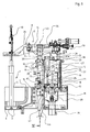
- Fig. 1 is partially a feeder 1 for a glass forming machine (not shown) shown.
- the feeder 1 has a feeder head 2 with a double Drop outlet 3 in a drip ring 6 and a plunger 4.
- the inventive device for periodic vertical up and Moving the plunger 4 is denoted by 5.
- the device 5 has a substantially horizontally extending Plunger holder 8 on.
- the plunger holder 8 has in the embodiment shown here a first part 14 and a second part 24.
- the first part 14 is attached to a support column 9, by means of two bearing bushes 10 and 11 mounted vertically movable up and down on a device-fixed frame 12 is.
- the second part 24 is hinged to the first part 14.
- the plunger 4 is relative by a height adjustment device 13 in its vertical position adjustable to the plunger holder 8.
- a console 15 is hinged thereto.
- the bracket 15 is on a side opposite to the attachment to the support column 9, by means of two vertically spaced carriages 16 and 17 movable up and down on a vertical guide rail 18.
- a drive for the lifting movement of the console 15 is a Elektroservomotor 21 to the Frame 12 mounted.
- the electric servomotor 21 is programmably controllable and drives via a coupling 20 to an axially fixed spindle 22, the is arranged parallel to the plunger 4 and the support column 9.
- the spindle 22 is mounted in a fixed to the frame 12 bearing housing 19 and stands with a secured against self-rotation nut 23, the console 15 is mounted, engaged.
- a pneumatic piston-cylinder unit 26 is arranged between the guide rail 18 and the support column 9 is adjacent to the Spindle 22 .
- a cylinder 27 of the unit 26 is attached to the frame 12 with one end 33, while a piston rod 25 of the unit 26 with one end 34 on the console 15 attacks.
- a bottom 29 of a piston 28 of the unit 26 is constantly connected to a compressed air source 30, while a top 31 of the piston 28 constantly connected via a silencer 32 to the atmosphere is.
- a cross-sectionally square securing rail 36 down.
- two backup roles 38 and 39 freely rotatably mounted with one screw 44 and 45, respectively. If the safety rail 36 together with the support column 9, the lifting movement for experiences the plunger 4, the backup rollers 38 and 39 roll along opposite Areas 41 and 42 of the safety rail 36 from, so that a Rotation of the support column 9 is prevented about its longitudinal axis 43.
- a depth stop 46 serves as Wegbeskyr by on it a bottom 47 of the console 15 can sit down and thereby the vertical downward movement of the Plungerhalter 8 is limited.
- the support column 9 an outer tube 55, which with the plunger holder 8 is connected (see Fig. 1).
- an inner tube 56 ( Figure 4).
- an adjusting spindle 59 is attached.
- the outer tube 55 has two opposing, Longitudinal holes arranged parallel to the longitudinal axis 43 of the outer tube 55 60 and 61 on. Across the slots 60, 61 extends a round Bolt 65 with horizontal longitudinal axis.
- the adjusting spindle 59 is available a concentric with the longitudinal axis 43 of the outer tube 55 threaded bore 66 of the bolt 65 in engagement.
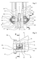
- the bolt 65 is connected outside of the outer tube 55 to the console 15, as shown in detail in Figs. 2 and 3.
- the console 15 has two welded bearing mounts 67 and 68, which alternatively also cast could be.
- In the bearing receivers 67, 68 is in each case a bearing bush 69 and 70 arranged.
- With a respective pin 71 or 72 of the bolt 65th rotatably mounted in the bushings 69 and 70.
- the bolt 65 by a respective lid 75 and 76, by means of screws 77th and 78, 79 and 80, respectively, to the pins 71, 72, against an axial one Move saved.
- the bearing receivers 67 and 68 each have a horizontal receiving slot on.
- the horizontal slot of the bearing receptacle 68 is shown and designated 83.
- a filler 85 is arranged in each case.
- Each filler 85 is connected by means of a through-bolt with associated Mother kept.
- One of the through bolts and the associated nut are shown in Fig. 3 and designated 86 and 87, respectively.
- the bushings 69 and 70 have top and bottom each have a horizontal sliding surface 88, 89, 90 and 91, which are in sliding contact with the receiving slots 83, so that each bushing 69, 70 between the respective filler 85 and a vertical Sliding wall 92 of the respective receiving slot 83 slidably is.
- the bolt 65 is relative to the receiving slots 83 of the bearing mounts 67 and 68 limited movable in a horizontal plane.
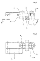
- the inner tube 56 has, as shown in FIG. 4 at a lower end of a socket 95th on, which is secured by means of grooved pins 96 and 97 on the inner tube 56.
- One Thrust bearing 98 which is disposed between the sleeve 95 and the outer tube 55 allows a low-friction rotation of the inner tube 56 relative to the Outer tube 55.
- the bushing 95 has inside parallel to the longitudinal axis 43 of the inner tube 56th extending guide grooves, of which in Fig. 4 two and shown with 99 and 100 are designated.
- a rotatable, axially fixed shaft 105 is arranged, which extends from below coaxially into the inner tube 56, which in the area the attachment of the adjusting spindle 59 bores 106 and 107 for loading and Having vent.
- the shaft 105 has on its circumference parallel to the Longitudinal axis 43 arranged guide wedges, of which in Fig. 4 shows three and labeled 108, 109 and 110. Each guide wedge 108, 109, 110 engages in one of the guide grooves 99, 100 of the inner tube 56 a.
- the shaft 105 can be rotated back and forth, to achieve a height adjustment of the plunger holder 8.
- a lever 112 clamping ring 113 can be the shaft 105 fix.
- a generated by the electric servomotor 21 lifting movement of the console 15th is transmitted to the inner tube 56 via the bolt 65 and the adjusting spindle 59.
- the ventilation holes 106, 107 of the inner tube 56 allow the associated axial relative movement of the shaft 105 in the inner tube 56.
- the piston-cylinder unit 26 provides a substantial amount Compensation of the weight of the console 15, the support column 9 and by the Supporting column 9 carried elements in the lifting movement.
Landscapes
- Chemical & Material Sciences (AREA)
- Engineering & Computer Science (AREA)
- Materials Engineering (AREA)
- Organic Chemistry (AREA)
- Transmission Devices (AREA)
- Injection Moulding Of Plastics Or The Like (AREA)
- Magnetic Heads (AREA)
Abstract
Description
Claims (10)
- Vorrichtung (5) zum periodischen senkrechten Auf- und Abbewegen wenigstens eines Plungers (4) in einem Speiserkopf (2) eines Speisers (1) für eine Glasformmaschine, um das Ausströmen schmelzflüssigen Glases aus dem Speiserkopf (2) zu beeinflussen,
wobei der wenigstens eine Plunger (4) an einem sich im wesentlichen waagerecht erstreckenden Plungerhalter (8) angeordnet ist,
wobei der Plungerhalter (8) durch eine an einem vorrichtungsfesten Rahmen (12) senkrecht auf und ab bewegbar gelagerte Tragsäule (9) getragen ist,
wobei die Tragsäule (9) in einem waagerechten Abstand von dem wenigstens einen Plunger (4) angeordnet ist,
wobei durch einen vorrichtungsfesten, programmierbar steuerbaren Elektromotor (21) eine axial festgelegte Spindel (22) hin und her drehend antreibbar ist,
wobei die Spindel (22) parallel zu und in waagerechtem Abstand von dem wenigstens einen Plunger (4) und der Tragsäule (9) angeordnet ist,
wobei mit der Spindel (22) eine gegen Eigendrehung gesicherte Mutter (23) im Eingriff steht,
wobei eine durch die Drehung der Spindel (22) erzeugte Hubbewegung der Mutter (23) auf die Tragsäule (9) und den Plungerhalter (8) übertragbar ist,
wobei an dem Rahmen (12) eine senkrechte Führungsschiene (18) in einem waagerechten Abstand von dem wenigstens einen Plunger (4) und der Tragsäule (9) befestigt ist,
und wobei der Elektromotor (21) an dem Rahmen (12) montiert ist,
dadurch gekennzeichnet, dass eine Konsole (15) einerseits an der Führungsschiene (18) auf und ab bewegbar geführt und andererseits an der Tragsäule (9) angelenkt ist,
und dass die Mutter (23) an der Konsole (15) montiert ist. - Vorrichtung nach Anspruch 1,
dadurch gekennzeichnet, dass der Elektromotor als Elektroservomotor (21) ausgebildet ist. - Vorrichtung nach Anspruch 1 oder 2,
dadurch gekennzeichnet, dass die Konsole (15) zwei in senkrechtem Abstand voneineinander angeordnete, an der Führungsschiene (18) geführte Schlitten (16,17) aufweist. - Vorrichtung nach einem der Ansprüche 1 bis 3,
dadurch gekennzeichnet, dass zwischen der Führungsschiene (18) und der Tragsäule (9) eine pneumatische Kolben-Zylinder-Einheit (26) angeordnet ist,
dass die Kolben-Zylinder-Einheit (26) mit ihrem einen Ende (33) an dem Rahmen (12) und mit ihrem anderen Ende (34) an der Konsole (15) angreift,
dass eine Unterseite (29) eines Kolbens (28) der Kolben-Zylinder-Einheit (26) ständig mit einer Druckluftquelle (30) verbunden ist,
und dass eine Oberseite (31) des Kolbens (28) ständig mit der Atmosphäre verbunden ist. - Vorrichtung nach einem der Ansprüche 1 bis 4,
dadurch gekennzeichnet, dass sich von einem rückwärtigen Fortsatz (35) des Plungerhalters (8) im Abstand von der Tragsäule (9) eine Sicherungsschiene (36) senkrecht nach unten erstreckt,
und dass an dem Rahmen (12) wenigstens eine im Eingriff mit der Sicherungsschiene (36) stehende, eine Drehung der Tragsäule (9) um ihre Längsachse (43) verhindernde Sicherungsrolle (38,39) drehbar gelagert ist. - Vorrichtung nach einem der Ansprüche 1 bis 5,
dadurch gekennzeichnet, dass die Tragsäule (9) ein mit dem Plungerhalter (8) verbundenes Außenrohr (55) und ein in radialem Abstand von und relativ zu dem Außenrohr (55) um seine Längsachse (43) drehbares Innenrohr (56) aufweist,
dass das Außenrohr (55) oberhalb des Innenrohrs (56) zwei gegenüberliegende, parallel zu der Längsachse (43) des Außenrohrs (55) angeordnete Langlöcher (60,61) aufweist,
dass sich quer durch die Langlöcher (60,61) ein Bolzen (65) mit waagerechter Längsachse erstreckt,
dass der Bolzen (65) außerhalb des Außenrohrs (55) mit der Konsole (15) verbunden ist und eine mit der Längsachse (43) des Außenrohrs (55) konzentrische Gewindebohrung (66) aufweist,
dass mit der Gewindebohrung (66) eine an einem oberen Ende des Innenrohrs (56) befestigte Einstellspindel (59) im Eingriff steht,
dass an dem Innenrohr (56) innen wenigstens eine parallel zu der Längsachse (43) des Innenrohrs (56) verlaufende Führungsnut (99,100) vorgesehen ist,
dass sich eine an dem Rahmen (12) drehbar angeordnete und axial festgelegte Welle (105) von unten koaxial in das Innenrohr (56) erstreckt,
dass die Welle (105) wenigstens einen parallel zu der Längsachse (43) des Innenrohrs (56) verlaufenden äußeren Führungskeil (108,109,110) aufweist, wobei jeder Führungskeil (108,109,110) in eine Führungsnut (99,100) eingreift,
und dass die Welle (105) zur Erzielung einer Höhengrundeinstellung des wenigstens einen Plungers (4) hin oder her drehbar ist. - Vorrichtung nach Anspruch 6,
dadurch gekennzeichnet, dass zwischen dem Außenrohr (55) und dem Innenrohr (56) ein Axiallager (98) angeordnet ist. - Vorrichtung nach Anspruch 6 oder 7,
dadurch gekennzeichnet, dass jede eingestellte Höhengrundeinstellung durch eine die weitere Drehung der Welle (105) blockierende, an dem Rahmen (12) befestigte Klemmvorrichtung (112,113) fixierbar ist. - Vorrichtung nach einem der Ansprüche 6 bis 8,
dadurch gekennzeichnet, dass der Bolzen (65) außerhalb des Außenrohrs (55) jeweils in einer Lagerbuchse (69,70) drehbar gelagert ist,
dass jede Lagerbuchse (69,70) oben und unten eine waagerechte Gleitfläche (88,89,90,91) aufweist,
und dass die Gleitflächen (88,89,90,91) jeder Lagerbuchse (69,70) in Gleitberührung mit jeweils einem waagerechten Aufnahmeschlitz (83) der Konsole (15) stehen. - Vorrichtung nach Anspruch 9,
dadurch gekennzeichnet, dass ein offenes Ende jedes Aufnahmeschlitzes (83) durch ein Füllstück (85) schließbar ist,
und dass jede Lagerbuchse (69,70) jeweils zwischen dem Füllstück (85) und einer senkrechten Begrenzungswand (92) des Aufnahmeschlitzes (83) mit Spiel waagerecht verschiebbar ist.
Applications Claiming Priority (2)
| Application Number | Priority Date | Filing Date | Title |
|---|---|---|---|
| DE20316501U DE20316501U1 (de) | 2003-10-25 | 2003-10-25 | Vorrichtung zum Auf- und Abbewegen von Plungern in einem Speiserkopf für eine Glasformmaschine |
| DE20316501U | 2003-10-25 |
Publications (2)
| Publication Number | Publication Date |
|---|---|
| EP1526118A1 true EP1526118A1 (de) | 2005-04-27 |
| EP1526118B1 EP1526118B1 (de) | 2006-08-23 |
Family
ID=30010960
Family Applications (1)
| Application Number | Title | Priority Date | Filing Date |
|---|---|---|---|
| EP04024143A Expired - Lifetime EP1526118B1 (de) | 2003-10-25 | 2004-10-09 | Vorrichtung zum Auf- und Abbewegen von Plungern in einem Speiserkopf für eine Glasformmaschine |
Country Status (3)
| Country | Link |
|---|---|
| EP (1) | EP1526118B1 (de) |
| AT (1) | ATE337278T1 (de) |
| DE (2) | DE20316501U1 (de) |
Cited By (1)
| Publication number | Priority date | Publication date | Assignee | Title |
|---|---|---|---|---|
| EP2163527A1 (de) * | 2008-09-12 | 2010-03-17 | Waltec Maschinen GmbH | Glasschmelzezufuhrvorrichtung |
Families Citing this family (3)
| Publication number | Priority date | Publication date | Assignee | Title |
|---|---|---|---|---|
| DE102004011647A1 (de) * | 2004-03-10 | 2005-09-29 | Heye International Gmbh | Verfahren und Vorrichtung zur Regelung der Glastropfenmasse bei der Herstellung von Hohlglasbehältern |
| DE102004022218A1 (de) * | 2004-05-04 | 2005-12-01 | Heye International Gmbh | Verfahren und Vorrichtung zur Erzeugung unterschiedlicher Glastropfenmassen bei der Herstellung von Glasgegenständen |
| DE102009052991B4 (de) * | 2009-11-12 | 2012-04-12 | Zwiesel Kristallglas Aktiengesellschaft | Glasspeisevorrichtung und ein Verfahren zum Bewegen eines Plungers einer Glasspeisevorrichtung |
Citations (5)
| Publication number | Priority date | Publication date | Assignee | Title |
|---|---|---|---|---|
| US2749665A (en) * | 1949-04-21 | 1956-06-12 | Emhart Mfg Co | Means for supporting and operating a glass feeder vertically reciprocable implement |
| US3201218A (en) * | 1961-12-27 | 1965-08-17 | Emhart Corp | Plunger type glass feeding apparatus |
| US4551163A (en) * | 1984-06-04 | 1985-11-05 | Emhart Industries, Inc. | Electronic glass feeder plunger operating mechanism |
| DE4231455A1 (de) * | 1992-09-19 | 1994-03-24 | Gps Glasprod Serv Gmbh | Feedermaschine zur Tropfenbildung aus flüssigem Glas |
| US5735926A (en) * | 1994-06-23 | 1998-04-07 | The Firm Hermann Heye | Apparatus for the driving of plungers in a feeder of a glass forming machine |
-
2003
- 2003-10-25 DE DE20316501U patent/DE20316501U1/de not_active Expired - Lifetime
-
2004
- 2004-10-09 DE DE502004001255T patent/DE502004001255D1/de not_active Expired - Lifetime
- 2004-10-09 AT AT04024143T patent/ATE337278T1/de not_active IP Right Cessation
- 2004-10-09 EP EP04024143A patent/EP1526118B1/de not_active Expired - Lifetime
Patent Citations (5)
| Publication number | Priority date | Publication date | Assignee | Title |
|---|---|---|---|---|
| US2749665A (en) * | 1949-04-21 | 1956-06-12 | Emhart Mfg Co | Means for supporting and operating a glass feeder vertically reciprocable implement |
| US3201218A (en) * | 1961-12-27 | 1965-08-17 | Emhart Corp | Plunger type glass feeding apparatus |
| US4551163A (en) * | 1984-06-04 | 1985-11-05 | Emhart Industries, Inc. | Electronic glass feeder plunger operating mechanism |
| DE4231455A1 (de) * | 1992-09-19 | 1994-03-24 | Gps Glasprod Serv Gmbh | Feedermaschine zur Tropfenbildung aus flüssigem Glas |
| US5735926A (en) * | 1994-06-23 | 1998-04-07 | The Firm Hermann Heye | Apparatus for the driving of plungers in a feeder of a glass forming machine |
Cited By (1)
| Publication number | Priority date | Publication date | Assignee | Title |
|---|---|---|---|---|
| EP2163527A1 (de) * | 2008-09-12 | 2010-03-17 | Waltec Maschinen GmbH | Glasschmelzezufuhrvorrichtung |
Also Published As
| Publication number | Publication date |
|---|---|
| EP1526118B1 (de) | 2006-08-23 |
| DE502004001255D1 (de) | 2006-10-05 |
| ATE337278T1 (de) | 2006-09-15 |
| DE20316501U1 (de) | 2003-12-24 |
Similar Documents
| Publication | Publication Date | Title |
|---|---|---|
| DE102007056266B4 (de) | Presse | |
| EP0769373B1 (de) | Vorrichtung zum Wechseln von Druckzylinderhülsen in Druckmaschinen | |
| EP0396904B1 (de) | Vorrichtung zum Anstellen und Abheben eines auf einen Formzylinder wirkenden Gegendruckzylinders | |
| EP3009538B1 (de) | Ballenöffner | |
| DE10155256A1 (de) | Flexodruckmaschine mit alternativ manuell und automatisch anstellbaren Farbübertragungswalzen | |
| EP1526118B1 (de) | Vorrichtung zum Auf- und Abbewegen von Plungern in einem Speiserkopf für eine Glasformmaschine | |
| DE102004008090A1 (de) | Vorrichtung zum Positionieren einer Walze in einem Farb- oder Feuchtwerk einer Rotationsdruckmaschine | |
| DE10209536B4 (de) | Druckmaschine, vorzugsweise Flexodruckmaschine | |
| DE4216781C2 (de) | Vorrichtung zur Aufnahme von Rotationskörperzapfen | |
| DE60121903T2 (de) | Eine Verstellvorrichtung zur Abgabe einer bestimmten Flüssigkeitsmenge in einer Abfüllanlage | |
| DE3443756A1 (de) | Vorrichtung zum anheben und gesteuerten ab- und aufwickeln einer trommel | |
| EP0681063A2 (de) | Fräsmaschine | |
| DE2652325A1 (de) | Anstellvorrichtung fuer ein walzgeruest | |
| DE19613341B4 (de) | Scherenhebetisch | |
| EP0655327B1 (de) | Tiefdruckfarbwerk | |
| DE20221164U1 (de) | Druckmaschine, vorzugsweise Flexodruckmaschine | |
| DE2923108C2 (de) | Treibwalzengerüst für eine Stranggießanlage | |
| DE494413C (de) | Maschine zum Bedrucken von Papier- und Stoffbahnen | |
| EP0976552A1 (de) | Lagerung für einen Zylinder in einer Druckmaschine | |
| DE3021771C2 (de) | Trommelgleitschleifmaschine | |
| DE3228476C2 (de) | ||
| DE4342226C2 (de) | Bohrständer, insbesondere für Kernbohrmaschinen | |
| DE2258893C3 (de) | Vorrichtung zum Bedrucken von Warenbahnen, wie Teppichen o.dgl. großer Breite mittels eines Siebdruckschablonenbandes | |
| EP4520531A1 (de) | Druckwerk mit verfahrbar angeordneten druckzylindern | |
| EP4563257A1 (de) | Rundbiegemaschine mit 2-dimensional einstellbarer unterwalze |
Legal Events
| Date | Code | Title | Description |
|---|---|---|---|
| PUAI | Public reference made under article 153(3) epc to a published international application that has entered the european phase |
Free format text: ORIGINAL CODE: 0009012 |
|
| AK | Designated contracting states |
Kind code of ref document: A1 Designated state(s): AT BE BG CH CY CZ DE DK EE ES FI FR GB GR HU IE IT LI LU MC NL PL PT RO SE SI SK TR |
|
| AX | Request for extension of the european patent |
Extension state: AL HR LT LV MK |
|
| 17P | Request for examination filed |
Effective date: 20050504 |
|
| 17Q | First examination report despatched |
Effective date: 20050607 |
|
| AKX | Designation fees paid |
Designated state(s): AT BE BG CH CY CZ DE DK EE ES FI FR GB GR HU IE IT LI LU MC NL PL PT RO SE SI SK TR |
|
| GRAP | Despatch of communication of intention to grant a patent |
Free format text: ORIGINAL CODE: EPIDOSNIGR1 |
|
| GRAS | Grant fee paid |
Free format text: ORIGINAL CODE: EPIDOSNIGR3 |
|
| GRAA | (expected) grant |
Free format text: ORIGINAL CODE: 0009210 |
|
| AK | Designated contracting states |
Kind code of ref document: B1 Designated state(s): AT BE BG CH CY CZ DE DK EE ES FI FR GB GR HU IE IT LI LU MC NL PL PT RO SE SI SK TR |
|
| PG25 | Lapsed in a contracting state [announced via postgrant information from national office to epo] |
Ref country code: RO Free format text: LAPSE BECAUSE OF FAILURE TO SUBMIT A TRANSLATION OF THE DESCRIPTION OR TO PAY THE FEE WITHIN THE PRESCRIBED TIME-LIMIT Effective date: 20060823 Ref country code: FI Free format text: LAPSE BECAUSE OF FAILURE TO SUBMIT A TRANSLATION OF THE DESCRIPTION OR TO PAY THE FEE WITHIN THE PRESCRIBED TIME-LIMIT Effective date: 20060823 Ref country code: IE Free format text: LAPSE BECAUSE OF FAILURE TO SUBMIT A TRANSLATION OF THE DESCRIPTION OR TO PAY THE FEE WITHIN THE PRESCRIBED TIME-LIMIT Effective date: 20060823 Ref country code: IT Free format text: LAPSE BECAUSE OF FAILURE TO SUBMIT A TRANSLATION OF THE DESCRIPTION OR TO PAY THE FEE WITHIN THE PRESCRIBED TIME-LIMIT;WARNING: LAPSES OF ITALIAN PATENTS WITH EFFECTIVE DATE BEFORE 2007 MAY HAVE OCCURRED AT ANY TIME BEFORE 2007. THE CORRECT EFFECTIVE DATE MAY BE DIFFERENT FROM THE ONE RECORDED. Effective date: 20060823 Ref country code: SK Free format text: LAPSE BECAUSE OF FAILURE TO SUBMIT A TRANSLATION OF THE DESCRIPTION OR TO PAY THE FEE WITHIN THE PRESCRIBED TIME-LIMIT Effective date: 20060823 Ref country code: NL Free format text: LAPSE BECAUSE OF FAILURE TO SUBMIT A TRANSLATION OF THE DESCRIPTION OR TO PAY THE FEE WITHIN THE PRESCRIBED TIME-LIMIT Effective date: 20060823 Ref country code: PL Free format text: LAPSE BECAUSE OF FAILURE TO SUBMIT A TRANSLATION OF THE DESCRIPTION OR TO PAY THE FEE WITHIN THE PRESCRIBED TIME-LIMIT Effective date: 20060823 Ref country code: SI Free format text: LAPSE BECAUSE OF FAILURE TO SUBMIT A TRANSLATION OF THE DESCRIPTION OR TO PAY THE FEE WITHIN THE PRESCRIBED TIME-LIMIT Effective date: 20060823 |
|
| REG | Reference to a national code |
Ref country code: GB Ref legal event code: FG4D Free format text: NOT ENGLISH |
|
| REG | Reference to a national code |
Ref country code: CH Ref legal event code: EP |
|
| REG | Reference to a national code |
Ref country code: IE Ref legal event code: FG4D Free format text: LANGUAGE OF EP DOCUMENT: GERMAN |
|
| REG | Reference to a national code |
Ref country code: CH Ref legal event code: NV Representative=s name: A. BRAUN, BRAUN, HERITIER, ESCHMANN AG PATENTANWAE |
|
| REF | Corresponds to: |
Ref document number: 502004001255 Country of ref document: DE Date of ref document: 20061005 Kind code of ref document: P |
|
| GBT | Gb: translation of ep patent filed (gb section 77(6)(a)/1977) |
Effective date: 20060920 |
|
| PG25 | Lapsed in a contracting state [announced via postgrant information from national office to epo] |
Ref country code: MC Free format text: LAPSE BECAUSE OF NON-PAYMENT OF DUE FEES Effective date: 20061031 |
|
| REG | Reference to a national code |
Ref country code: SE Ref legal event code: TRGR |
|
| PG25 | Lapsed in a contracting state [announced via postgrant information from national office to epo] |
Ref country code: DK Free format text: LAPSE BECAUSE OF FAILURE TO SUBMIT A TRANSLATION OF THE DESCRIPTION OR TO PAY THE FEE WITHIN THE PRESCRIBED TIME-LIMIT Effective date: 20061123 Ref country code: BG Free format text: LAPSE BECAUSE OF FAILURE TO SUBMIT A TRANSLATION OF THE DESCRIPTION OR TO PAY THE FEE WITHIN THE PRESCRIBED TIME-LIMIT Effective date: 20061123 |
|
| PG25 | Lapsed in a contracting state [announced via postgrant information from national office to epo] |
Ref country code: ES Free format text: LAPSE BECAUSE OF FAILURE TO SUBMIT A TRANSLATION OF THE DESCRIPTION OR TO PAY THE FEE WITHIN THE PRESCRIBED TIME-LIMIT Effective date: 20061204 |
|
| PG25 | Lapsed in a contracting state [announced via postgrant information from national office to epo] |
Ref country code: PT Free format text: LAPSE BECAUSE OF FAILURE TO SUBMIT A TRANSLATION OF THE DESCRIPTION OR TO PAY THE FEE WITHIN THE PRESCRIBED TIME-LIMIT Effective date: 20070125 |
|
| NLV1 | Nl: lapsed or annulled due to failure to fulfill the requirements of art. 29p and 29m of the patents act | ||
| ET | Fr: translation filed | ||
| REG | Reference to a national code |
Ref country code: IE Ref legal event code: FD4D |
|
| PLBE | No opposition filed within time limit |
Free format text: ORIGINAL CODE: 0009261 |
|
| STAA | Information on the status of an ep patent application or granted ep patent |
Free format text: STATUS: NO OPPOSITION FILED WITHIN TIME LIMIT |
|
| 26N | No opposition filed |
Effective date: 20070524 |
|
| BERE | Be: lapsed |
Owner name: HEYE INTERNATIONAL G.M.B.H. Effective date: 20061031 |
|
| PG25 | Lapsed in a contracting state [announced via postgrant information from national office to epo] |
Ref country code: AT Free format text: LAPSE BECAUSE OF NON-PAYMENT OF DUE FEES Effective date: 20061009 |
|
| PG25 | Lapsed in a contracting state [announced via postgrant information from national office to epo] |
Ref country code: GR Free format text: LAPSE BECAUSE OF FAILURE TO SUBMIT A TRANSLATION OF THE DESCRIPTION OR TO PAY THE FEE WITHIN THE PRESCRIBED TIME-LIMIT Effective date: 20061124 |
|
| REG | Reference to a national code |
Ref country code: CH Ref legal event code: PFA Owner name: HEYE INTERNATIONAL GMBH Free format text: HEYE INTERNATIONAL GMBH#LOHPLATZ 1#31683 OBERNKIRCHEN (DE) -TRANSFER TO- HEYE INTERNATIONAL GMBH#LOHPLATZ 1#31683 OBERNKIRCHEN (DE) |
|
| PG25 | Lapsed in a contracting state [announced via postgrant information from national office to epo] |
Ref country code: EE Free format text: LAPSE BECAUSE OF FAILURE TO SUBMIT A TRANSLATION OF THE DESCRIPTION OR TO PAY THE FEE WITHIN THE PRESCRIBED TIME-LIMIT Effective date: 20060823 |
|
| PG25 | Lapsed in a contracting state [announced via postgrant information from national office to epo] |
Ref country code: LU Free format text: LAPSE BECAUSE OF NON-PAYMENT OF DUE FEES Effective date: 20061009 Ref country code: TR Free format text: LAPSE BECAUSE OF FAILURE TO SUBMIT A TRANSLATION OF THE DESCRIPTION OR TO PAY THE FEE WITHIN THE PRESCRIBED TIME-LIMIT Effective date: 20060823 Ref country code: HU Free format text: LAPSE BECAUSE OF FAILURE TO SUBMIT A TRANSLATION OF THE DESCRIPTION OR TO PAY THE FEE WITHIN THE PRESCRIBED TIME-LIMIT Effective date: 20070224 |
|
| PG25 | Lapsed in a contracting state [announced via postgrant information from national office to epo] |
Ref country code: CY Free format text: LAPSE BECAUSE OF FAILURE TO SUBMIT A TRANSLATION OF THE DESCRIPTION OR TO PAY THE FEE WITHIN THE PRESCRIBED TIME-LIMIT Effective date: 20060823 |
|
| PG25 | Lapsed in a contracting state [announced via postgrant information from national office to epo] |
Ref country code: BE Free format text: LAPSE BECAUSE OF FAILURE TO SUBMIT A TRANSLATION OF THE DESCRIPTION OR TO PAY THE FEE WITHIN THE PRESCRIBED TIME-LIMIT Effective date: 20061031 |
|
| REG | Reference to a national code |
Ref country code: DE Ref legal event code: R082 Ref document number: 502004001255 Country of ref document: DE Representative=s name: SOBISCH & KRAMM, DE |
|
| REG | Reference to a national code |
Ref country code: CH Ref legal event code: PCAR Free format text: NEW ADDRESS: HOLBEINSTRASSE 36-38, 4051 BASEL (CH) |
|
| REG | Reference to a national code |
Ref country code: FR Ref legal event code: PLFP Year of fee payment: 12 |
|
| REG | Reference to a national code |
Ref country code: FR Ref legal event code: PLFP Year of fee payment: 13 |
|
| REG | Reference to a national code |
Ref country code: FR Ref legal event code: PLFP Year of fee payment: 14 |
|
| REG | Reference to a national code |
Ref country code: FR Ref legal event code: PLFP Year of fee payment: 15 |
|
| REG | Reference to a national code |
Ref country code: DE Ref legal event code: R082 Ref document number: 502004001255 Country of ref document: DE Representative=s name: MICHALSKI HUETTERMANN & PARTNER PATENTANWAELTE, DE |
|
| PGFP | Annual fee paid to national office [announced via postgrant information from national office to epo] |
Ref country code: FR Payment date: 20221028 Year of fee payment: 19 |
|
| PGFP | Annual fee paid to national office [announced via postgrant information from national office to epo] |
Ref country code: SE Payment date: 20221019 Year of fee payment: 19 Ref country code: IT Payment date: 20221026 Year of fee payment: 19 Ref country code: GB Payment date: 20221019 Year of fee payment: 19 Ref country code: DE Payment date: 20220628 Year of fee payment: 19 Ref country code: CZ Payment date: 20220930 Year of fee payment: 19 |
|
| PGFP | Annual fee paid to national office [announced via postgrant information from national office to epo] |
Ref country code: CH Payment date: 20221024 Year of fee payment: 19 |
|
| PG25 | Lapsed in a contracting state [announced via postgrant information from national office to epo] |
Ref country code: CZ Free format text: LAPSE BECAUSE OF NON-PAYMENT OF DUE FEES Effective date: 20231009 |
|
| REG | Reference to a national code |
Ref country code: DE Ref legal event code: R119 Ref document number: 502004001255 Country of ref document: DE |
|
| REG | Reference to a national code |
Ref country code: SE Ref legal event code: EUG |
|
| REG | Reference to a national code |
Ref country code: CH Ref legal event code: PL |
|
| GBPC | Gb: european patent ceased through non-payment of renewal fee |
Effective date: 20231009 |
|
| PG25 | Lapsed in a contracting state [announced via postgrant information from national office to epo] |
Ref country code: GB Free format text: LAPSE BECAUSE OF NON-PAYMENT OF DUE FEES Effective date: 20231009 |
|
| PG25 | Lapsed in a contracting state [announced via postgrant information from national office to epo] |
Ref country code: CH Free format text: LAPSE BECAUSE OF NON-PAYMENT OF DUE FEES Effective date: 20231031 |
|
| PG25 | Lapsed in a contracting state [announced via postgrant information from national office to epo] |
Ref country code: GB Free format text: LAPSE BECAUSE OF NON-PAYMENT OF DUE FEES Effective date: 20231009 Ref country code: FR Free format text: LAPSE BECAUSE OF NON-PAYMENT OF DUE FEES Effective date: 20231031 Ref country code: DE Free format text: LAPSE BECAUSE OF NON-PAYMENT OF DUE FEES Effective date: 20240501 Ref country code: CH Free format text: LAPSE BECAUSE OF NON-PAYMENT OF DUE FEES Effective date: 20231031 |
|
| PG25 | Lapsed in a contracting state [announced via postgrant information from national office to epo] |
Ref country code: SE Free format text: LAPSE BECAUSE OF NON-PAYMENT OF DUE FEES Effective date: 20231010 |
|
| PG25 | Lapsed in a contracting state [announced via postgrant information from national office to epo] |
Ref country code: IT Free format text: LAPSE BECAUSE OF NON-PAYMENT OF DUE FEES Effective date: 20231009 |
|
| PG25 | Lapsed in a contracting state [announced via postgrant information from national office to epo] |
Ref country code: IT Free format text: LAPSE BECAUSE OF NON-PAYMENT OF DUE FEES Effective date: 20231009 |