EP1525971B1 - Corps de bouteille en resine synthetique comprenant une poignee - Google Patents
Corps de bouteille en resine synthetique comprenant une poignee Download PDFInfo
- Publication number
- EP1525971B1 EP1525971B1 EP03771443A EP03771443A EP1525971B1 EP 1525971 B1 EP1525971 B1 EP 1525971B1 EP 03771443 A EP03771443 A EP 03771443A EP 03771443 A EP03771443 A EP 03771443A EP 1525971 B1 EP1525971 B1 EP 1525971B1
- Authority
- EP
- European Patent Office
- Prior art keywords
- bottle
- handle
- fitting
- embedded
- portions
- Prior art date
- Legal status (The legal status is an assumption and is not a legal conclusion. Google has not performed a legal analysis and makes no representation as to the accuracy of the status listed.)
- Expired - Lifetime
Links
- 229920003002 synthetic resin Polymers 0.000 title claims description 16
- 239000000057 synthetic resin Substances 0.000 title claims description 16
- 229920000139 polyethylene terephthalate Polymers 0.000 claims description 64
- 239000005020 polyethylene terephthalate Substances 0.000 claims description 64
- 238000005299 abrasion Methods 0.000 claims description 18
- 229920005989 resin Polymers 0.000 claims description 9
- 239000011347 resin Substances 0.000 claims description 9
- -1 polyethylene terephthalate Polymers 0.000 claims description 5
- 230000002093 peripheral effect Effects 0.000 claims description 2
- 238000000071 blow moulding Methods 0.000 description 20
- 208000035874 Excoriation Diseases 0.000 description 17
- 238000000465 moulding Methods 0.000 description 13
- 238000000034 method Methods 0.000 description 11
- 230000008569 process Effects 0.000 description 11
- 238000009499 grossing Methods 0.000 description 7
- 238000002425 crystallisation Methods 0.000 description 6
- 230000008025 crystallization Effects 0.000 description 5
- 230000000694 effects Effects 0.000 description 5
- 230000004044 response Effects 0.000 description 5
- 230000009471 action Effects 0.000 description 4
- 238000001746 injection moulding Methods 0.000 description 4
- 238000012360 testing method Methods 0.000 description 3
- 239000012141 concentrate Substances 0.000 description 2
- 238000010586 diagram Methods 0.000 description 2
- 230000006872 improvement Effects 0.000 description 2
- 238000004381 surface treatment Methods 0.000 description 2
- 239000004743 Polypropylene Substances 0.000 description 1
- 230000002411 adverse Effects 0.000 description 1
- 235000013334 alcoholic beverage Nutrition 0.000 description 1
- 238000007664 blowing Methods 0.000 description 1
- 230000008859 change Effects 0.000 description 1
- 230000001419 dependent effect Effects 0.000 description 1
- 230000001066 destructive effect Effects 0.000 description 1
- 238000011161 development Methods 0.000 description 1
- 230000018109 developmental process Effects 0.000 description 1
- 235000011389 fruit/vegetable juice Nutrition 0.000 description 1
- 230000012447 hatching Effects 0.000 description 1
- 238000010348 incorporation Methods 0.000 description 1
- 238000003780 insertion Methods 0.000 description 1
- 230000037431 insertion Effects 0.000 description 1
- 230000007246 mechanism Effects 0.000 description 1
- 229920013716 polyethylene resin Polymers 0.000 description 1
- 229920001155 polypropylene Polymers 0.000 description 1
- 235000014214 soft drink Nutrition 0.000 description 1
- 238000005482 strain hardening Methods 0.000 description 1
- 239000002699 waste material Substances 0.000 description 1
Images


Classifications
-
- B—PERFORMING OPERATIONS; TRANSPORTING
- B65—CONVEYING; PACKING; STORING; HANDLING THIN OR FILAMENTARY MATERIAL
- B65D—CONTAINERS FOR STORAGE OR TRANSPORT OF ARTICLES OR MATERIALS, e.g. BAGS, BARRELS, BOTTLES, BOXES, CANS, CARTONS, CRATES, DRUMS, JARS, TANKS, HOPPERS, FORWARDING CONTAINERS; ACCESSORIES, CLOSURES, OR FITTINGS THEREFOR; PACKAGING ELEMENTS; PACKAGES
- B65D23/00—Details of bottles or jars not otherwise provided for
- B65D23/10—Handles
- B65D23/104—Handles formed separately
- B65D23/106—Handles formed separately the gripping region of the handle extending between the neck and the base of the bottle or jar and being located in a radial plane comprising the axis of the bottle or jar
-
- B—PERFORMING OPERATIONS; TRANSPORTING
- B29—WORKING OF PLASTICS; WORKING OF SUBSTANCES IN A PLASTIC STATE IN GENERAL
- B29C—SHAPING OR JOINING OF PLASTICS; SHAPING OF MATERIAL IN A PLASTIC STATE, NOT OTHERWISE PROVIDED FOR; AFTER-TREATMENT OF THE SHAPED PRODUCTS, e.g. REPAIRING
- B29C49/00—Blow-moulding, i.e. blowing a preform or parison to a desired shape within a mould; Apparatus therefor
- B29C49/08—Biaxial stretching during blow-moulding
-
- B—PERFORMING OPERATIONS; TRANSPORTING
- B29—WORKING OF PLASTICS; WORKING OF SUBSTANCES IN A PLASTIC STATE IN GENERAL
- B29C—SHAPING OR JOINING OF PLASTICS; SHAPING OF MATERIAL IN A PLASTIC STATE, NOT OTHERWISE PROVIDED FOR; AFTER-TREATMENT OF THE SHAPED PRODUCTS, e.g. REPAIRING
- B29C49/00—Blow-moulding, i.e. blowing a preform or parison to a desired shape within a mould; Apparatus therefor
- B29C49/20—Blow-moulding, i.e. blowing a preform or parison to a desired shape within a mould; Apparatus therefor of articles having inserts or reinforcements ; Handling of inserts or reinforcements
-
- B—PERFORMING OPERATIONS; TRANSPORTING
- B65—CONVEYING; PACKING; STORING; HANDLING THIN OR FILAMENTARY MATERIAL
- B65D—CONTAINERS FOR STORAGE OR TRANSPORT OF ARTICLES OR MATERIALS, e.g. BAGS, BARRELS, BOTTLES, BOXES, CANS, CARTONS, CRATES, DRUMS, JARS, TANKS, HOPPERS, FORWARDING CONTAINERS; ACCESSORIES, CLOSURES, OR FITTINGS THEREFOR; PACKAGING ELEMENTS; PACKAGES
- B65D23/00—Details of bottles or jars not otherwise provided for
- B65D23/10—Handles
-
- B—PERFORMING OPERATIONS; TRANSPORTING
- B65—CONVEYING; PACKING; STORING; HANDLING THIN OR FILAMENTARY MATERIAL
- B65D—CONTAINERS FOR STORAGE OR TRANSPORT OF ARTICLES OR MATERIALS, e.g. BAGS, BARRELS, BOTTLES, BOXES, CANS, CARTONS, CRATES, DRUMS, JARS, TANKS, HOPPERS, FORWARDING CONTAINERS; ACCESSORIES, CLOSURES, OR FITTINGS THEREFOR; PACKAGING ELEMENTS; PACKAGES
- B65D25/00—Details of other kinds or types of rigid or semi-rigid containers
- B65D25/28—Handles
-
- B—PERFORMING OPERATIONS; TRANSPORTING
- B29—WORKING OF PLASTICS; WORKING OF SUBSTANCES IN A PLASTIC STATE IN GENERAL
- B29C—SHAPING OR JOINING OF PLASTICS; SHAPING OF MATERIAL IN A PLASTIC STATE, NOT OTHERWISE PROVIDED FOR; AFTER-TREATMENT OF THE SHAPED PRODUCTS, e.g. REPAIRING
- B29C49/00—Blow-moulding, i.e. blowing a preform or parison to a desired shape within a mould; Apparatus therefor
- B29C49/20—Blow-moulding, i.e. blowing a preform or parison to a desired shape within a mould; Apparatus therefor of articles having inserts or reinforcements ; Handling of inserts or reinforcements
- B29C2049/2017—Blow-moulding, i.e. blowing a preform or parison to a desired shape within a mould; Apparatus therefor of articles having inserts or reinforcements ; Handling of inserts or reinforcements outside the article
-
- B—PERFORMING OPERATIONS; TRANSPORTING
- B29—WORKING OF PLASTICS; WORKING OF SUBSTANCES IN A PLASTIC STATE IN GENERAL
- B29C—SHAPING OR JOINING OF PLASTICS; SHAPING OF MATERIAL IN A PLASTIC STATE, NOT OTHERWISE PROVIDED FOR; AFTER-TREATMENT OF THE SHAPED PRODUCTS, e.g. REPAIRING
- B29C49/00—Blow-moulding, i.e. blowing a preform or parison to a desired shape within a mould; Apparatus therefor
- B29C49/20—Blow-moulding, i.e. blowing a preform or parison to a desired shape within a mould; Apparatus therefor of articles having inserts or reinforcements ; Handling of inserts or reinforcements
- B29C2049/2021—Inserts characterised by the material or type
- B29C2049/2034—Attachments, e.g. hooks to hold or hang the blown article
- B29C2049/2039—Handles, e.g. handles or grips on bottles
-
- B—PERFORMING OPERATIONS; TRANSPORTING
- B29—WORKING OF PLASTICS; WORKING OF SUBSTANCES IN A PLASTIC STATE IN GENERAL
- B29C—SHAPING OR JOINING OF PLASTICS; SHAPING OF MATERIAL IN A PLASTIC STATE, NOT OTHERWISE PROVIDED FOR; AFTER-TREATMENT OF THE SHAPED PRODUCTS, e.g. REPAIRING
- B29C49/00—Blow-moulding, i.e. blowing a preform or parison to a desired shape within a mould; Apparatus therefor
- B29C49/20—Blow-moulding, i.e. blowing a preform or parison to a desired shape within a mould; Apparatus therefor of articles having inserts or reinforcements ; Handling of inserts or reinforcements
- B29C2049/2021—Inserts characterised by the material or type
- B29C2049/2069—Inserts characterised by the material or type moulded in combination, e.g. injection moulded in the same mould before or after blow-moulding
-
- B—PERFORMING OPERATIONS; TRANSPORTING
- B29—WORKING OF PLASTICS; WORKING OF SUBSTANCES IN A PLASTIC STATE IN GENERAL
- B29C—SHAPING OR JOINING OF PLASTICS; SHAPING OF MATERIAL IN A PLASTIC STATE, NOT OTHERWISE PROVIDED FOR; AFTER-TREATMENT OF THE SHAPED PRODUCTS, e.g. REPAIRING
- B29C49/00—Blow-moulding, i.e. blowing a preform or parison to a desired shape within a mould; Apparatus therefor
- B29C49/42—Component parts, details or accessories; Auxiliary operations
- B29C49/78—Measuring, controlling or regulating
- B29C49/786—Temperature
- B29C2049/7861—Temperature of the preform
- B29C2049/7862—Temperature of the preform characterised by temperature values or ranges
-
- B—PERFORMING OPERATIONS; TRANSPORTING
- B29—WORKING OF PLASTICS; WORKING OF SUBSTANCES IN A PLASTIC STATE IN GENERAL
- B29C—SHAPING OR JOINING OF PLASTICS; SHAPING OF MATERIAL IN A PLASTIC STATE, NOT OTHERWISE PROVIDED FOR; AFTER-TREATMENT OF THE SHAPED PRODUCTS, e.g. REPAIRING
- B29C2949/00—Indexing scheme relating to blow-moulding
- B29C2949/07—Preforms or parisons characterised by their configuration
- B29C2949/0715—Preforms or parisons characterised by their configuration the preform having one end closed
-
- B—PERFORMING OPERATIONS; TRANSPORTING
- B29—WORKING OF PLASTICS; WORKING OF SUBSTANCES IN A PLASTIC STATE IN GENERAL
- B29C—SHAPING OR JOINING OF PLASTICS; SHAPING OF MATERIAL IN A PLASTIC STATE, NOT OTHERWISE PROVIDED FOR; AFTER-TREATMENT OF THE SHAPED PRODUCTS, e.g. REPAIRING
- B29C2949/00—Indexing scheme relating to blow-moulding
- B29C2949/07—Preforms or parisons characterised by their configuration
- B29C2949/079—Auxiliary parts or inserts
-
- B—PERFORMING OPERATIONS; TRANSPORTING
- B29—WORKING OF PLASTICS; WORKING OF SUBSTANCES IN A PLASTIC STATE IN GENERAL
- B29C—SHAPING OR JOINING OF PLASTICS; SHAPING OF MATERIAL IN A PLASTIC STATE, NOT OTHERWISE PROVIDED FOR; AFTER-TREATMENT OF THE SHAPED PRODUCTS, e.g. REPAIRING
- B29C49/00—Blow-moulding, i.e. blowing a preform or parison to a desired shape within a mould; Apparatus therefor
- B29C49/02—Combined blow-moulding and manufacture of the preform or the parison
- B29C49/06—Injection blow-moulding
-
- B—PERFORMING OPERATIONS; TRANSPORTING
- B29—WORKING OF PLASTICS; WORKING OF SUBSTANCES IN A PLASTIC STATE IN GENERAL
- B29K—INDEXING SCHEME ASSOCIATED WITH SUBCLASSES B29B, B29C OR B29D, RELATING TO MOULDING MATERIALS OR TO MATERIALS FOR MOULDS, REINFORCEMENTS, FILLERS OR PREFORMED PARTS, e.g. INSERTS
- B29K2067/00—Use of polyesters or derivatives thereof, as moulding material
-
- B—PERFORMING OPERATIONS; TRANSPORTING
- B29—WORKING OF PLASTICS; WORKING OF SUBSTANCES IN A PLASTIC STATE IN GENERAL
- B29K—INDEXING SCHEME ASSOCIATED WITH SUBCLASSES B29B, B29C OR B29D, RELATING TO MOULDING MATERIALS OR TO MATERIALS FOR MOULDS, REINFORCEMENTS, FILLERS OR PREFORMED PARTS, e.g. INSERTS
- B29K2995/00—Properties of moulding materials, reinforcements, fillers, preformed parts or moulds
- B29K2995/0037—Other properties
- B29K2995/0072—Roughness, e.g. anti-slip
- B29K2995/0073—Roughness, e.g. anti-slip smooth
-
- B—PERFORMING OPERATIONS; TRANSPORTING
- B29—WORKING OF PLASTICS; WORKING OF SUBSTANCES IN A PLASTIC STATE IN GENERAL
- B29L—INDEXING SCHEME ASSOCIATED WITH SUBCLASS B29C, RELATING TO PARTICULAR ARTICLES
- B29L2031/00—Other particular articles
- B29L2031/46—Knobs or handles, push-buttons, grips
- B29L2031/463—Grips, handles
-
- B—PERFORMING OPERATIONS; TRANSPORTING
- B29—WORKING OF PLASTICS; WORKING OF SUBSTANCES IN A PLASTIC STATE IN GENERAL
- B29L—INDEXING SCHEME ASSOCIATED WITH SUBCLASS B29C, RELATING TO PARTICULAR ARTICLES
- B29L2031/00—Other particular articles
- B29L2031/712—Containers; Packaging elements or accessories, Packages
- B29L2031/7158—Bottles
Definitions
- This invention relates to a large-size synthetic resin bottle with a handle, in which the handle is fitted firmly to the bottle by using the handle as an insert and by biaxially drawing and blow-molding the bottle of a polyethylene terephthalate resin (hereinafter referred to as PET resin).
- PET resin polyethylene terephthalate resin
- a synthetic resin bottle with a handle in which the handle has been previously injection-molded into a certain shape and is used as an insert, and in which the PET bottle is biaxially drawn and blow-molded.
- the handle is made of the same PET as used in the bottle, rather than a polyethylene resin or a polypropylene resin, so that the bottles can be separated and disposed easily at the time of waste disposal.
- Japanese Patent Application (OPI) No. 1994-298253 discloses that the fitting portions of the handle coming in contact with the bottle are crystallized to a degree of crystallinity of 10% or more. This makes it possible for the handle to be made of PET just as the bottle is made of PET. When the PET handle is fitted, usually the bottle tends to be ruptured because slide gets worse, but the crystallization prevents the bottle from rupturing during the drawing and deformation.
- a technical problem of this invention is to improve the low slide between bottle and handle made of the same PET.
- An object of this invention is to obtain a biaxially drawn, blow-molded PET bottle, in which the PET handle is firmly fitted to the bottle as the insert, merely by an ordinary biaxial drawing and blow molding process, without requiring any dedicated operation.
- the handle disclosed in the Japanese Patent Application (OPI) No. 2001-328636 is as shown in Fig. 16 and Figs. 24-27 .
- the handle comprises a grip plate 11' in a vertical strip shape, embedded projecting pieces 14' disposed on the front end faces at the extended end of this grip plate 11', a pair of engaging ridges 15' in a vertical ridge shape disposed on the sides facing each other, a pair of embedded fitting portions K' that serve as strong undercut fittings to the bottle 1', a pair of fitting beams 12' in a vertical rod shape, and a pair of connecting arms 12a' in the curved rod shape, which connect between the pair of fitting beams 12' at both the upper and lower ends of the grip plate 11'.
- the afore-mentioned bottle with a handle can be obtained when injection-molded PET perform P' is blow-molded into the bottle 1'.
- the previously injection-molded PET handle 10' is fitted to the bottom of the handle-fitting recession 3' at the rear of the body 2' of the bottle 1' by means of simultaneous insert molding.
- the heated and softened PET preform P' is smoothly deformed as its shape follows the shapes of the embedded projecting pieces 14' and the engaging ridges 15', which are the inserts of the handle 10' and are fitted firmly to the bottle 1'.
- High fitting strength between the handle 10' and the bottle 1' is obtained by allowing the PET bottle wall portion to get around smoothly and tightly the peripheries of the handle inserts.
- EP 0650900 discloses as handle for mounting to a synthetic resin bottle.
- the handle is formed integrally with a pair of mount beam pieces which have engagement projections inner sides thereof.
- JP 2000335584 upon which the preamble of claim 1 is based, discloses a resin grip structure for incorporation with a blow molded container.
- the resin grip includes end faces having a plurality of longitudinally extending protrusions.
- Another technical problem of this invention is to prevent abrasions from occurring at the inserts during the biaxial drawing and blow molding operation under a high blowing pressure.
- Another object of this invention is to provide a synthetic resin bottle with a handle, which has high safety, easy handling ability, and good appearance even in the case of large-size bottles reaching a capacity of a few liters.
- the inventors of this application concentrated their thoughts on the factors that affect the above-described friction resistance badly, and found out that the cause of aggravated friction resistance is concerned with the viscoelasticity of the PET preform, which is molded into the bottle, and that the friction resistance greatly changes especially with the drawing state.
- the invention has thus been made from a discovery that the friction resistance can be reduced by changing the up-and-down property of the handle surfaces in response to the drawing state of the PET resin.
- the up-and-down property giving high slidability to the surfaces of the handle inserts is adjusted by the tests conducted justifiably for the details of the surfaces and also in response to the shapes and sizes of the bottles. Divided broadly, it is preferred that the portions in contact with the PET preform in the initial stage of drawing have a finely textured up-and-down pattern. In the more advanced drawing stage, it is effective that the surfaces have so-called mirror-finish.
- a relatively large up-and-down pattern such as narrow grooves, is effective because these grooves reduce the area of contact and lower the friction resistance.
- Bottles which fully get around the handle inserts, have high fitting strength and no abrasion, can be provided at a low cost.
- a finely textured up-and-down pattern may be closely formed in advance on the surfaces of handle inserts that come in contact with the bottle during the process of biaxial drawing and blow molding.
- a finely textured up-and-down pattern is closely formed on the surfaces of the handle inserts that come in contact with the bottle during the process of drawing and deformation.
- the uppermost portions of the ups are easily softened by the heat coming from the bottle, making the insert surfaces much slippery. Due to the affinity between bottle and the surfaces of handle inserts, there occurs routinely an increased level of friction resistance caused by the contact between these two portions. This friction resistance can be readily and securely reduced by the up-and-down pattern on the surfaces.
- the reduced contact friction resistance found between the expanding bottle and the surfaces of the handle inserts is derived from the surface structure of handle inserts.
- the bottle can be safely molded, and the handle can be firmly fitted to the bottle, simply by using an injection-molded handle as the insert, with insert surfaces having a specified structure, and by molding the bottle in an ordinary biaxial drawing and blow molding process.
- the handle consists of a pair of fitting beams disposed in parallel to each other in the standing position; a grip plate integrally disposed to connect between the pair of the fitting beams at both the upper and lower ends; embedded projecting pieces disposed on the outer end face of each fitting beam; and a pair of engaging ridges disposed face-to-face to each other on the opposed surfaces of the fitting beams, and that the fitting beams, the embedded projecting pieces, and the engaging ridges constitute the handle inserts.
- the embedded projecting pieces are stuck out against the wall of the bottle during the process of drawing and deformation. And a tensile force acts between the wall portions contacting the embedded projecting pieces and the other wall portions that are being drawn and deformed. But because of the highly slidable property of the up-and-down pattern on the surfaces of the embedded projecting pieces, this tensile force does not concentrate locally, but acts almost uniformly on the entire wall portions that come in contact with the embedded projecting pieces. In fact, the force used for drawing is not so much concentrated locally as to exert a destructive force on the bottle, and thus the bottle is safely drawn and molded.
- the engaging ridges are in a position to act as the weirs standing in the way of the moving bottle wall that is drawn in the direction of expansion.
- the finely textured up-and-down pattern is closely formed on the surfaces of the engaging ridges that come in contact with the bottle wall when the wall is drawn and moving. Due to the highly slidable property of the up-and-down pattern, there is an improvement in the slide on the surfaces of the engaging ridges.
- the up-and-down pattern reduces the contact friction resistance arising between the expanding bottle wall and the engaging ridges, and the drawn and moving wall of the bottle climbs over and gets around the engaging ridges smoothly.
- the many lateral, narrow grooves are disposed on the front sides of the engaging ridges, where an expanding and moving bottle wall portion is pushed toward the engaging ridges.
- many lateral, narrow grooves serve to reduce the area of contact between the engaging ridges and the bottle, and lower the contact friction resistance arising between these portions. Therefore, the expanding and moving bottle wall portion smoothly climbs over and gets around the engaging ridges.
- the handle specified in claim 1 comprises a pair of fitting beams disposed in parallel to each other in the standing position, a grip plate integrally disposed to connect between the pair of the fitting beams at both the upper and lower ends, embedded projecting pieces disposed on the outer end face of each fitting beam, a pair of engaging ridges, disposed face-to-face to each other on the opposed surfaces of the fitting beams, and many lateral, narrow grooves disposed on the front sides of the engaging ridges, which are a part of the handle inserts that come in contact with the bottle during the process of biaxial drawing and blow molding.
- the engaging ridges are in a position to act as the weirs standing in the way of the moving bottle wall that is drawn in the direction of expansion.
- many lateral, narrow grooves are disposed on the front sides of the engaging ridges that come in contact with the bottle wall when the wall is drawn and moving. These narrow grooves substantially reduce the area of contact between the expanding bottle wall and the front sides of the engaging ridges, and lower the contact friction resistance between these two portions.
- the drawn and moving wall of the bottle climbs over and gets around the engaging ridges smoothly.
- the reduced contact friction resistance found between the expanding bottle and the surfaces of the handle inserts is derived from the handle structure.
- the bottle can be safely molded, and the handle can be firmly fitted to the bottle, simply by using the injection-molded handle as the insert and molding the bottle in an ordinary biaxial drawing and blow molding process.
- the preform comes in contact with the front end faces of the embedded projecting portions, gets around corners thereof, and thus has relatively small opportunities in which the PET surface suffers abrasions.
- the PET wall portion does not get around these arms, but is pressed against the front end faces of these arms by a large force caused by air blow. Since at that time, the PET wall portion is drawn and expands while sliding along the front end faces in a rasping way, abrasions are expected to occur.
- the PET preform when used in the softened state as is the case in this invention, undergoes a large change in viscoelasticity, depending on the temperature and the drawing record. Yet it is presumed that the improved slidability caused by the smoothed contact areas becomes effective after the PET drawing has been in much progress and the PET is right in the process of large strain hardening.
- the configuration that the connecting arms may have mirror finished surfaces only in the specific areas.
- the embedded projecting portions specified in the invention may comprise embedded ridges which are located near the corner set by the outer end face and the opposed side of each fitting beam, with the cross-section of each embedded ridge having a generally triangular shape formed by one side of the right angle going down from the opposed side in the roughly vertical direction and the other side of the right angle extending perpendicularly from the outer end face.
- the configuration of the embedded ridges has been devised with the goal of accomplishing deformation of the preform along the peripheries of the embedded projecting portions at the initial stage of preform drawing.
- This goal can be accomplished by disposing the front end faces of the embedded projecting portions at the positions close to the outer wall of the preform when the handle is set inside the blow split mold, and by giving a simple shape to the entire embedded projecting portions.
- Each embedded projecting portion specified may comprise embedded projecting pieces disposed on the outer end face of each fitting beam, and also comprises an engaging ridge projecting from the opposed surface of each fitting beam.
- the configuration of the embedded projecting portions allows the bottles of larger sizes to be molded without abrasions and with no need of changing the shape of conventional embedded projecting portions.
- a finely textured up-and-down pattern is closely formed in advance on the surfaces of handle inserts that come in contact with the bottle during the process of biaxial drawing and blow molding, except for the surfaces of the connecting arms.
- the handle inserts mainly comprising the embedded projecting portions but excluding the connecting arms, are the portions with which the blow-molded PET bottle comes in contact during the initial stage of drawing.
- a finely textured up-and-down pattern is closely formed in these insert portions to reduce the friction resistance. Since the PET bottle wall portion is allowed to get around the embedded projecting portions tightly, it is fully possible for the fitting strength to be increased to a satisfactory level.
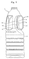
- Figs. 1-9 show the bottle with a hand in the first embodiment of this invention.
- the bottle of this invention comprises the bottle 1 and the handle 10.
- the bottle 1 is a biaxially drawn, blow-molded PET product of a large size (1.0 liter or more), and is provided with a recession 3 that has been caved in at the rear of the upper half of the bottomed cylindrical body 2.
- the handle 10 is an injection-molded PET product, which is fitted firmly to the recession 3 by an insert molding means.
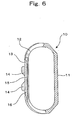
- the recession 3 of the bottle 1 comprises a vertical projecting wall 5, which is located in the center of recession bottom 4, where the flat projecting wall 5 stands upright, except for the upper and lower ends of the recession 3.
- the projecting wall 5 is relatively wide and extends vertically over the total height of the recession 3, with the wall height being roughly constant from side to side.
- Expanded side portions 6 in the vertical ridge shape are disposed on both sides of the vertical projecting wall 5. Due to the existence of the expanded side portion 6, an engaging groove 7 is formed between each expanded side portion 6 and the recession bottom 4. Fitting holes 8 in a blank-hole shape are formed in the central area of the recession bottom 4, as taken along the height of the expanded side portions 6. In addition, a pair of step-like fitting-hole edges 9 is formed at positions opposite to the respective engaging grooves 7. The expanded side portions 6, the engaging grooves 7, the fitting holes 8, and the fitting-hole edges 9 together constitute the fitting portions of the bottle 1, by which the handle 10 is fitted to the bottle 1.
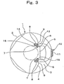
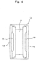
- the handle 10 comprises a grip plate 11 in a vertical strip shape; a pair of fitting beams 12, which are straight in the center and are bent and connected to the grip plate 11 at both the upper and lower ends, with two beams being disposed in parallel to each other; a pair of engaging ridges 15 disposed straight on the sides of respective fitting beams 12 so as to face each other; and embedded projecting pieces 14 disposed in the central areas of both outer end faces 13 of the fitting beams 12.
- the outer end faces 13 of the fitting beams 12 come in contact with the central portion of the recession bottom 4. Like this central portion, the outer end faces 13, too, are flat and straight.
- the fitting beams 12 are provided with the embedded projecting pieces 14 and the engaging ridges 15, along with these outer end faces 13, all of which constitute the fitting portions of the handle 10.
- the embedded projecting pieces 14 used for fitting the handle 10 have totally smooth and rounded surfaces so as to lower the friction resistance upon contact with the bottle 1.
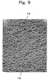
- a finely textured up-and-down pattern 16 has been formed in advance on the surfaces of at least the fitting portions or the inserts of the handle 10. As shown in Fig. 9 , a referential photograph, the finely textured up-and-down pattern 16 spreads closely in the depth ranging from 5 to 20" m. Hatching shown by dotted lines in Figs. 5-8 indicates those portions where the above-described up-and-down pattern 16 has been formed closely.
- the handle 10 is fitted to the bottle 1 by using the fitting portions of the handle 10 as the inserts and subjecting the bottle 1 to biaxial drawing and blow molding.In this molding operation, using the fitting portions of the handle 10 as the inserts, the fitting portions of the bottle 1, including the expanded side portions 6, the engaging grooves 7, the fitting holes 8, and the fitting-hole edges 9 that are in the positions opposite to the engaging grooves 7, are formed surrounding tightly the fitting portions of the handle 10 with no space between.
- the bottle 1 is biaxially drawn and blow-molded at a molding temperature in the range of 90-120°C.
- the uppermost portions of the ups in the up-and-down pattern 16 are easily softened by the heat coming from the bottle, making the insert surfaces much slippery.
- the friction resistance caused by the contact between the bottle 1 and the surfaces of the handle inserts can be readily and securely reduced by the softened surfaces. Therefore, the bottle 1 can be safely subjected to the biaxial drawing and blow molding operation, without causing any rupture.
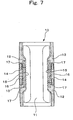
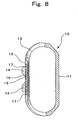
- Figs. 7 and 8 show another example of the handle 10 in the first embodiment of this invention.
- Many lateral, narrow grooves 17 are disposed on the front sides of the engaging ridges 15, with each front side being curved toward the crest of the ridge. These narrow grooves 17 reduce the area of contact between the front sides of the engaging ridges 15 and the expanding wall portion of the bottle 1, thereby lowering the friction resistance caused by the contact between the bottle 1 and the engaging ridges 15.
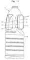
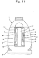
- Figs. 10-15 show the bottle with a handle in the second embodiment of this invention.
- the bottle in this embodiment comprises the bottle 1 and the handle 10.
- the bottle 1 is a biaxially drawn, blow-molded PET product of a large size (1.0 liter or more), and is provided with a recession 3 that has been caved in at the rear of the upper half of the bottomed cylindrical body 2.
- the handle 10 is an injection-molded PET product, which is fitted firmly to the recession 3 by an insert molding means.
- the recession 3 of the bottle 1 comprises a vertical projecting wall 5, which is located in the center of recession bottom 4, where the flat projecting wall 5 stands upright, except for the upper and lower ends of the recession 3.
- the vertical projecting wall 5 is relatively wide and extends vertically over the total height of the recession 3, with the wall height being roughly constant from side to side.
- Expanded side portions 6 in the vertical ridge shape are disposed on both sides of the vertical projecting wall 5. Due to the existence of the expanded side portion 6, an engaging groove 7 is formed between each expanded side portion 6 and the recession bottom 4. Fitting holes 8 in a blank-hole shape are formed in the central area of the recession bottom 4, as taken along the height of the expanded side portions 6. In addition, a pair of step-like fitting-hole edges 9 is formed at positions opposite to the respective engaging grooves 7. The expanded side portions 6, the engaging grooves 7, the fitting holes 8, and the fitting-hole edges 9 together constitute the fitting portions of the bottle 1, by which the handle 10 is fitted to the bottle 1.
- the handle 10 comprises a grip plate 11 in a vertical strip shape; a pair of fitting beams 12, which are straight in the center and are bent and connected to the grip plate 11 at both the upper and lower ends, with two beams being disposed in parallel to each other; a pair of engaging ridges 15 disposed straight on the sides of respective fitting beams 12 so as to face each other; and embedded projecting pieces 14 disposed in the central areas of both outer end faces 13 of the fitting beams 12.
- the outer end faces 13 of the fitting beams 12 come in contact with the central portion of the recession bottom 4. Like this central portion, the outer end faces 13, too, are flat and straight.
- the fitting beams 12 are provided with the embedded projecting pieces 14 and the engaging ridges 15, along with these outer end faces 13, all of which constitute the fitting portions of the handle 10.
- the embedded projecting pieces 14 used for fitting the handle 10 have totally smooth and rounded surfaces. Each piece 14 has a forefront groove 14a in the stick-out end face so as to lower the contact friction resistance when the embedded projecting pieces 14 come in contact with the wall of the bottle 1. Similarly, many lateral, narrow grooves 17 are disposed in the front surfaces of the engaging ridges 15 to lower the friction resistance upon contact with the bottle 1.
- the handle 10 is fitted to the bottle 1 by using the fitting portions of the handle 10 as the inserts and subjecting the bottle 1 to biaxial drawing and blow molding.
- the fitting portions of the bottle 1 including the expanded side portions 6, the engaging grooves 7, the fitting holes 8, and the fitting-hole edges 9 that are in the positions opposite to the engaging grooves 7, are formed surrounding tightly the fitting portions of the handle 10 with no space.
- the embedded projecting pieces 14 of the handle 10 have been designed to have totally smooth rounded surfaces.
- the area of contact of the embedded projecting pieces 14 with the bottle 1 has been reduced by notching the forefront grooves 14a of a vertical slit type in the stick-out end faces of the embedded projecting pieces 14. Due to these measures, the contact friction resistance is neither biased locally nor increased, even if such resistance occurs between the embedded projecting pieces 14 and the wall portion of the bottle 1 that comes in contact with the embedded projecting pieces 14. Therefore, the bottle 1 can be safely subjected to the biaxial drawing and blow molding operation, without causing any rupture.
- the bottle 1 can be smoothly drawn and deformed because these grooves 17 serve to limit to a low level the contact friction resistance that develops between the engaging ridges 15 and the bottle 1.
- this portion gets around the engaging ridges 15 smoothly and reaches the rear side, thus forming the expanded side portions 6 stably without fail.
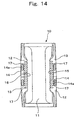
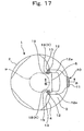
- Figs. 16-23 show the bottle with a handle in the third embodiment of this invention.
- the bottle in this third embodiment comprises the bottle 1 and the handle 10.
- the bottle 1 is a biaxially drawn, blow-molded PET product of a large size (1.0 liter or more), and is provided with a recession 3 that has been caved in at the rear of the upper half of the bottomed cylindrical body 2.
- the handle 10 is an injection-molded PET product, and is fitted firmly to the recession 3 by an insert molding means.
- the recession 3 of the bottle 1 comprises a vertical projecting wall 5, which is located in the center of recession bottom 4, where the flat projecting wall 5 stands upright, except for the upper and lower ends of the recession 3.
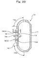
- This wall 5 is relatively wide and extends vertically over the total height of the recession 3, with the wall height being roughly constant from side to side (See Fig. 17 ).
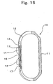
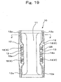
- Figs. 18-21 show the handle 10.
- a pair of fitting beams 12 in a straight bar shape is disposed in parallel to each other and is connected to the vertical grip plate 11 through the intermediary of the connecting arms 12a in a curved rod shape.
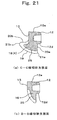
- the embedded ridges 18 are a form of the embedded projecting portions K and are located near the corner set by the outer end face 13 and the opposed side 12d of each fitting beam 12.
- the cross-section of the mbedded ridges 18 has a generally triangular shape formed by one side of the right angle going down from the opposed side in the almost vertical direction and the other side of the right angle extending perpendicularly from the outer end face 12d (See Fig. 21(a) ).
- the end face 19 of the embedded ridge 18 corresponds to the hypotenuse of a right-angled triangle in its cross-section, and forms a gentle arc. Many lateral, narrow grooves 25 are notched in the outer peripheral surface of each embedded ridge 18. This device improves the slidability of the PET preform P when it is in the softened state during the blow molding.
- the embedded ridge 18 in this embodiment is a two-peak ridge with a low area 18a in between.
- the engaging ridge 15 is disposed as an insert, which has a shape obtained by deleting a portion perpendicular to the outer end face 13 of the fitting beam 12 from the cross-section of the embedded ridge 18 (See Fig. 21(b) ).
- the two-peak form of the embedded ridge 18 is intended to reduce the handle weight and to improve the fitting strength further by allowing the wall of the PET bottle to get around this low area 18a.
- designing an embedded ridge 18 one skilled in the art can decide on whether the two-peak form is adequate or not, giving consideration to the moldability, because a ridge without the low area 18a has also full fitting strength.
- the embedded ridge 18 may have three or more peaks, depending on the purpose.
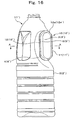
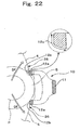
- the surfaces of the curved connecting arms 12a have been smoothed in advance. This improves the slidability of the drawn and expanding PET preform P during the biaxial drawing and blow molding operation using the handle 10 as the insert, and also prevents the bottle 1 from getting damages caused by friction.
- the pair of upper connecting arms 12a has been smoothed over the range indicated by 12C in Fig. 22 .
- the area to be smoothed can be selected.
- the pair of lower connecting arms 12a can be smoothed, if necessary.
- the handle 10 is fitted to the bottle 1 by using the handle 10 as the insert and biaxially drawing and blow-molding the bottle 1.
- the embedded ridge 18 is disposed at a position opposite the neighborhood of outer wall of the preform P in such a manner that the front end face 19 of the embedded ridge 18 is stuck out.
- the more close to the connecting portion of the grip plate 11 is the outer end face 12b of the connecting arms 12a positioned, the more distant from the outer wall of the preform P it stays, as compared with the front end face 19 of the embedded ridge 18 and the outer end face 13 of the fitting beam 12 (See Fig. 17 ).
- the PET preform P is expanded by air blow. At the initial stage of drawing, the preform P comes in contact with the front end face 19, covers it, and then gets around both corners 21a and 21b. At one corner 21a, the preform P deforms along the rear side 20a of the embedded ridge 18 and reaches the opposed side 12d. At the other corner 21b, the preform P deforms along the left side 20b of the embedded ridge 18 and the outer end face 13 of the fitting beam 12. Finally the preform P reaches the edge of the outer side 12e of the fitting beam 12, and thus, the insertion of the handle 10 into the recession 3 of the bottle 1 is completed. Since the embedded ridge 18 has a generally triangular shape in its cross-section, the PET preform P is allowed to get around the embedded ridge 18 tightly along its outer surfaces (See Fig. 21(a) ).
- Fig. 22 is an explanatory diagram showing estimated deformation of the preform P at a height of the well upper portion of each connecting arms 12a near the connection to the grip plate 11 (the height of line F-F in Fig. 19 ).
- the preform P presumably comes in contact with the end face 12b of the connecting arms 12a in the state in which the preform P has been drawn and expanded considerably more than when the preform P has come in contact with the front end faces 19 of the embedded ridges 18 or with the outer end faces 13 of the fitting beams 12.
- the preform P is further drawn and deformed, while sliding along the end face 12b of the connecting arms 12a without getting around the connecting arms 12a so largely as to reach the rear side.
- the arrows Df in Fig. 22 indicate the estimated directions in which the preform P is expanded and deformed.
- Bottles with a 4-liter capacity in the shape shown in the third embodiment were blow-molded to determine the smoothing effect of especially the connecting arms used in the bottle of this invention.
- abrasions were found at a high frequency, especially at positions near the upper connecting arms (Abrasive wall portion 26 in Fig. 22 ). These abrasions could have been prevented from occurring by smoothing beforehand those areas where expanding preform P comes in contact with the upper connecting arms 12a (Smoothed area 12c in Fig. 22 ).
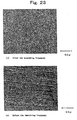
- Figs. 23(a) and 23(b) are referential photographs showing surface states of the connecting arms 12a before and after the above-described smoothing treatment.
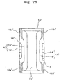
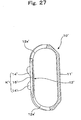
- the handle having a shape of embedded projecting portions was described in conventional art and are as shown in Figs. 24-27 . In such a handle, similar action and effect were also demonstrated, and abrasions were eliminated, in the insert molding of a handle into larger-size bottles.
- the up-and-down property of the surfaces of the handle inserts is adjusted in response to the softening and drawing state of the PET preform that is deformed and molded into the bottle. This adjustment causes the friction resistance to be reduced between the handle inserts and the blow-molded PET bottle. For instance, for the handle portions coming in contact with the PET bottle in the initial stage of drawing, a finely textured up-and-down pattern is formed. For the portions contacted in a relatively advanced stage of drawing, it is effective for the surfaces to have no up-and-down pattern but to have the so-called mirror-finish.
- a finely textured up-and-down pattern is closely formed on the surfaces of the handle inserts. This surface pattern lowers the friction resistance caused by the contact between the engaging ridges and the expanding bottle wall.
- the PET handle can be molded simply by an injection molding means, with no need of post-treatment, and can be used as the insert to the body of a biaxially drawn and blow-molded PET bottle. Thus, it is possible to avoid any inconvenience, which may be created under the circumstances where the operation for molding the bottle with a handle gets complicated by employing the PET handle.
- Sliding action is derived from the finely textured up-and-down pattern on the surfaces of embedded projecting pieces, even if these pieces, a part of the handle inserts, are stuck out against the wall of the bottle during the process of drawing and deformation. Under this condition, the bottle is safely drawn and molded because the tensile force does not concentrate locally on the wall portions that come in contact with the embedded projecting pieces.
- the engaging ridges a part of the handle inserts, have good slidability because a finely textured up-and-down pattern is formed on the surfaces.
- the expanding and moving wall portion of the bottle smoothly gets around and climbs over the engaging ridges.
- the PET handle can be molded simply by an injection molding means, with no need of post-treatment, and can be used as the insert to the body of a biaxially drawn and blow-molded PET bottle. Thus, it is possible to avoid any inconvenience, which may be created under the circumstances where the operation for molding the bottle with a handle gets complicated by employing the PET handle.
- the embedded projecting pieces are a part of handle inserts, and have smooth rounded surfaces, which prevent a large tensile force from being focused locally on the portion of the expanding bottle wall that comes in contact with the embedded projecting pieces. Thus, the drawing and molding of the bottle can be safely achieved.
- the embedded projecting pieces are stuck out against the wall of the bottle, but the forefront grooves notched in the stick-out end faces reduce the area of contact.
- the bottle wall portion Upon contact with the embedded projecting pieces, the bottle wall portion ceases to expand and deform.
- the reduced contact area ensures that the wall portion in contact with the handle continues to expand and deform.
- Abrasions can be prevented from occurring, by smoothing the surfaces of the connecting arms that come in contact with the bottle so that the slidability is improved between the connecting-arm surfaces and the softened PET preform P, which is right in the process of drawing and expansion.
- the preform completely accomplishes deformation along the peripheries of the embedded projecting portions at the initial stage of drawing and expansion. Consequently, it is possible for the PET bottle wall to get around the handle inserts quite smoothly. It is also possible for the bottle and the handle to obtain high fitting strength enough to be fully applicable to the bottles of larger sizes.
Landscapes
- Engineering & Computer Science (AREA)
- Mechanical Engineering (AREA)
- Manufacturing & Machinery (AREA)
- Details Of Rigid Or Semi-Rigid Containers (AREA)
- Blow-Moulding Or Thermoforming Of Plastics Or The Like (AREA)
Claims (6)
- Bouteille en résine synthétique avec poignée, qui comprend :une bouteille biaxialement étirée et moulée-soufflée (1) constituée d'une résine de polyéthylène téréphtalate ; etune poignée (10), un produit moulé par injection d'une résine de polyéthylène téréphtalate, qui est ajustée fermement sur la bouteille sous forme d'insert,dans laquelle les surfaces de portions d'insert de ladite poignée (10), qui viennent en contact avec la bouteille (1), ont un motif haut et bas qui donne aux surfaces une haute glissabilité pour la résine de polyéthylène téréphtalate dans l'état ramolli etétiré dans lequel une préforme est biaxialement étirée et moulée-soufflée dans la bouteille, dans laquelle en outrela bouteille (1) comporte une partie en retrait (3) qui a été creusée dans l'arrière du corps (2) et comprenant également une paroi saillante verticale (5) disposée dans la partie centrale du fond de ladite partie en retrait (3) ; etla poignée (10) comprend :une paire de poutres d'ajustement (12) disposées en parallèle l'une à l'autre dans la position debout ;des bras de raccordement (12a) qui sont courbés et raccordés aux extrémités supérieures et inférieures desdites poutres d'ajustement (12) ;une plaque de préhension (11) disposée solidairement pour se raccorder entre la paire desdites poutres d'ajustement (12) par l'intermédiaire desdits bras de raccordement (12a) ; etdes portions saillantes incorporées (K), qui sont disposées sur ladite paire de poutres d'ajustement (12) et sont utilisées comme des pièces de fixation à entaille fermes à ajuster sur le fond de partie en retrait (4) de ladite bouteille (1),dans laquelle lesdits bras de raccordement (12a), une partie desdites poutres d'ajustement (12) et lesdites portions saillantes incorporées (K) constituent les inserts de poignée qui sont ajustés sur le fond de partie en retrait (4) des deux côtés de la paroi saillante verticale (5) de la bouteille (1) caractérisée en ce que lesdits bras de raccordement (12a) comportent des portions couvertes par une surface de fini miroir qui vient en contact avec la bouteille (1) à mesure que la préforme est biaxialement étirée et moulée-soufflée en la bouteille (1), les surfaces de fini miroir empêchant une abrasion de la bouteille (1) par lesdits bras de raccordement (12a) pendant la dilatation de la préforme.
- Bouteille en résine synthétique avec poignée selon la revendication 1, dans laquelle les surfaces de fini miroir des bras de raccordement (12a) en sont limitées à une portion.
- Bouteille en résine synthétique avec poignée selon la revendication 1 ou 2, dans laquelle lesdites portions saillantes incorporées (K) comprennent des arêtes incorporées (18) qui sont situées près d'un coin établi par une face d'extrémité externe (13) et un côté opposé (14a) de chaque poutre d'ajustement (12), la section desdites arêtes incorporées (18) ayant une forme grossièrement triangulaire formée par un côté de l'angle droit descendant depuis ledit côté opposé (12d) dans la direction grossièrement verticale et l'autre côté dudit angle droit s'étendant perpendiculairement depuis ladite face d'extrémité externe (13).
- Bouteille en résine synthétique avec poignée selon la revendication 3, dans laquelle de nombreuses nervures étroites latérales (25) sont disposées dans la surface périphérique externe de chaque arête incorporée.
- Bouteille en résine synthétique avec poignée selon la revendication 1 ou 2, dans laquelle chaque portion saillante incorporée (14) comprend des pièces saillantes incorporées (14) disposées sur la face d'extrémité externe (13) de chaque poutre d'ajustement (12), et comprend également une arête de mise en prise (15) faisant saillie depuis la surface opposée de chaque poutre d'ajustement (12).
- Bouteille en résine synthétique avec poignée selon l'une quelconque des revendications 1 à 5, dans laquelle un motif haut et bas finement texturé (16) a été formé à l'avance sur les surfaces d'inserts de la poignée (10) à l'exception des surfaces des bras de raccordement (12a).
Priority Applications (1)
| Application Number | Priority Date | Filing Date | Title |
|---|---|---|---|
| EP11160860.0A EP2347883B1 (fr) | 2002-07-31 | 2003-07-31 | Bouteille en résine synthétique dotée d'une poignée |
Applications Claiming Priority (7)
| Application Number | Priority Date | Filing Date | Title |
|---|---|---|---|
| JP2002222865 | 2002-07-31 | ||
| JP2002222866A JP3948659B2 (ja) | 2002-07-31 | 2002-07-31 | 把手付き合成樹脂製壜体 |
| JP2002222865A JP3948658B2 (ja) | 2002-07-31 | 2002-07-31 | 把手付き合成樹脂製壜体 |
| JP2002222866 | 2002-07-31 | ||
| JP2002225119 | 2002-08-30 | ||
| JP2002255119A JP3948662B2 (ja) | 2002-08-30 | 2002-08-30 | 把手付き合成樹脂製壜体 |
| PCT/JP2003/009710 WO2004011229A1 (fr) | 2002-07-31 | 2003-07-31 | Corps de bouteille en resine synthetique comprenant une poignee |
Related Child Applications (2)
| Application Number | Title | Priority Date | Filing Date |
|---|---|---|---|
| EP11160860.0A Division-Into EP2347883B1 (fr) | 2002-07-31 | 2003-07-31 | Bouteille en résine synthétique dotée d'une poignée |
| EP11160860.0A Division EP2347883B1 (fr) | 2002-07-31 | 2003-07-31 | Bouteille en résine synthétique dotée d'une poignée |
Publications (3)
| Publication Number | Publication Date |
|---|---|
| EP1525971A1 EP1525971A1 (fr) | 2005-04-27 |
| EP1525971A4 EP1525971A4 (fr) | 2007-05-09 |
| EP1525971B1 true EP1525971B1 (fr) | 2012-09-05 |
Family
ID=31191871
Family Applications (2)
| Application Number | Title | Priority Date | Filing Date |
|---|---|---|---|
| EP11160860.0A Expired - Lifetime EP2347883B1 (fr) | 2002-07-31 | 2003-07-31 | Bouteille en résine synthétique dotée d'une poignée |
| EP03771443A Expired - Lifetime EP1525971B1 (fr) | 2002-07-31 | 2003-07-31 | Corps de bouteille en resine synthetique comprenant une poignee |
Family Applications Before (1)
| Application Number | Title | Priority Date | Filing Date |
|---|---|---|---|
| EP11160860.0A Expired - Lifetime EP2347883B1 (fr) | 2002-07-31 | 2003-07-31 | Bouteille en résine synthétique dotée d'une poignée |
Country Status (7)
| Country | Link |
|---|---|
| US (1) | US7108146B2 (fr) |
| EP (2) | EP2347883B1 (fr) |
| KR (1) | KR100989709B1 (fr) |
| CN (1) | CN100532068C (fr) |
| AU (1) | AU2003252743A1 (fr) |
| TW (1) | TWI263581B (fr) |
| WO (1) | WO2004011229A1 (fr) |
Families Citing this family (19)
| Publication number | Priority date | Publication date | Assignee | Title |
|---|---|---|---|---|
| KR100960195B1 (ko) * | 2002-07-31 | 2010-05-27 | 가부시키가이샤 요시노 고교쇼 | 손잡이부착 합성수지제 용기체 |
| CN100395162C (zh) * | 2004-05-25 | 2008-06-18 | 株式会社开拓 | 带把手吹塑成形瓶 |
| US20080251492A1 (en) * | 2005-03-15 | 2008-10-16 | Colgate-Palmolive Company | Overmolded Containers With Improved Gripping and Methods of Manufacture Thereof |
| KR100787191B1 (ko) | 2006-08-28 | 2007-12-21 | 한국화학연구원 | 각형비가 큰 판상 알파알루미나 결정체 및 이의 제조방법 |
| JP4805067B2 (ja) * | 2006-08-30 | 2011-11-02 | 株式会社吉野工業所 | 把手付ボトル容器 |
| US8714386B2 (en) | 2006-08-30 | 2014-05-06 | Yoshino Kogyosho Co., Ltd. | Bottle container with handle |
| CN101541640B (zh) * | 2007-03-30 | 2012-08-22 | 株式会社吉野工业所 | 带把手的合成树脂制瓶体 |
| USD612247S1 (en) | 2009-05-29 | 2010-03-23 | Tropicana Products, Inc. | Bottle |
| USD619468S1 (en) | 2009-05-29 | 2010-07-13 | Tropicana Products, Inc. | Bottle |
| US8668100B2 (en) | 2010-06-30 | 2014-03-11 | S.C. Johnson & Son, Inc. | Bottles with top loading resistance |
| US8851311B2 (en) | 2010-12-06 | 2014-10-07 | S.C. Johnson & Son, Inc. | Bottle with top loading resistance |
| US8662329B2 (en) | 2010-12-06 | 2014-03-04 | S.C. Johnson & Son, Inc. | Bottle with top loading resistance with front and back ribs |
| USD660714S1 (en) | 2010-12-06 | 2012-05-29 | S.C. Johnson & Son, Inc. | Bottle |
| JP5985798B2 (ja) * | 2011-05-27 | 2016-09-06 | 株式会社吉野工業所 | 把手付きボトル |
| MX2015007595A (es) | 2012-12-14 | 2016-03-21 | Nissei Asb Machine Co Ltd | Molde para envases con asa, metodo para fabricar el envase con asa, y envase con asa. |
| CN107718513B (zh) | 2013-06-28 | 2020-01-17 | 日精Asb机械株式会社 | 带把手容器的成形装置及用于该装置的成形用模具和成形用模具单元 |
| NZ747182A (en) * | 2016-04-04 | 2022-09-30 | Integrated Plastics Pty Ltd | Ergonomic integral handle assembly |
| USD900613S1 (en) | 2019-10-25 | 2020-11-03 | Niagara Bottling, Llc | Bottle |
| JP7496747B2 (ja) * | 2020-09-25 | 2024-06-07 | 株式会社吉野工業所 | 把手付きボトル |
Family Cites Families (16)
| Publication number | Priority date | Publication date | Assignee | Title |
|---|---|---|---|---|
| JPH0628896B2 (ja) * | 1990-06-04 | 1994-04-20 | 東洋製罐株式会社 | 把手付合成樹脂容器の製造方法及び装置 |
| JP2998820B2 (ja) * | 1992-11-18 | 2000-01-17 | 株式会社吉野工業所 | 把手付き合成樹脂製壜体とその成形方法 |
| JPH06298253A (ja) * | 1993-04-12 | 1994-10-25 | Mitsubishi Plastics Ind Ltd | 取手付ポリエステル製ボトル |
| KR100305543B1 (ko) * | 1993-05-17 | 2002-08-14 | 가부시키가이샤 요시노 고교쇼 | 손잡이를갖는합성수지제병체와그제조방법 |
| JPH0780921A (ja) * | 1993-09-17 | 1995-03-28 | Toppan Printing Co Ltd | 把手付二軸延伸ブロー成形ボトルの製造方法及び把手 |
| JPH07156952A (ja) * | 1993-10-13 | 1995-06-20 | Toppan Printing Co Ltd | 把手付二軸延伸ブロー成形ボトル |
| JPH07276478A (ja) * | 1994-04-08 | 1995-10-24 | Toppan Printing Co Ltd | 把手付二軸延伸ブロー成形ボトル |
| US5931324A (en) * | 1995-03-31 | 1999-08-03 | Graham Packaging Company, L.P. | Plastic container and non-integral handle |
| US5622579A (en) * | 1995-03-31 | 1997-04-22 | Graham Packaging Corporation | Method for attachment of a service device to a container |
| CA2183688C (fr) * | 1996-08-20 | 2005-10-25 | Akiho Ota | Bouteille de resine synthetique a poignee de prehension |
| USD404308S (en) * | 1997-04-03 | 1999-01-19 | Yoshino Kogyosho Co., Ltd. | Container with handle |
| JPH1134155A (ja) * | 1997-07-14 | 1999-02-09 | Yoshino Kogyosho Co Ltd | 把手付き合成樹脂製壜体 |
| KR100388699B1 (ko) * | 1997-11-28 | 2003-06-25 | 미쓰비시 쥬시 가부시끼가이샤 | 플라스틱 보틀용 손잡이 및 손잡이가 붙은 플라스틱 보틀. |
| US6012597A (en) * | 1998-03-18 | 2000-01-11 | Mitsubishi Plastics, Inc. | Polyester bottle with a handle and method of manufacturing the same |
| JP3939878B2 (ja) | 1999-05-24 | 2007-07-04 | 株式会社吉野工業所 | 合成樹脂製中空容器の把手体とそれを用いた把手付きの合成樹脂製中空容器 |
| JP4045524B2 (ja) | 2000-05-19 | 2008-02-13 | 株式会社吉野工業所 | 合成樹脂製壜体の把手 |
-
2003
- 2003-07-31 CN CNB038011964A patent/CN100532068C/zh not_active Expired - Lifetime
- 2003-07-31 EP EP11160860.0A patent/EP2347883B1/fr not_active Expired - Lifetime
- 2003-07-31 TW TW092121159A patent/TWI263581B/zh not_active IP Right Cessation
- 2003-07-31 EP EP03771443A patent/EP1525971B1/fr not_active Expired - Lifetime
- 2003-07-31 KR KR1020047004913A patent/KR100989709B1/ko not_active Expired - Fee Related
- 2003-07-31 WO PCT/JP2003/009710 patent/WO2004011229A1/fr not_active Ceased
- 2003-07-31 US US10/508,516 patent/US7108146B2/en not_active Expired - Lifetime
- 2003-07-31 AU AU2003252743A patent/AU2003252743A1/en not_active Abandoned
Also Published As
| Publication number | Publication date |
|---|---|
| AU2003252743A1 (en) | 2004-02-16 |
| TWI263581B (en) | 2006-10-11 |
| EP2347883A1 (fr) | 2011-07-27 |
| US7108146B2 (en) | 2006-09-19 |
| CN1564736A (zh) | 2005-01-12 |
| KR100989709B1 (ko) | 2010-10-26 |
| TW200404666A (en) | 2004-04-01 |
| EP1525971A4 (fr) | 2007-05-09 |
| US20050115919A1 (en) | 2005-06-02 |
| WO2004011229A1 (fr) | 2004-02-05 |
| EP1525971A1 (fr) | 2005-04-27 |
| CN100532068C (zh) | 2009-08-26 |
| KR20050025126A (ko) | 2005-03-11 |
| EP2347883B1 (fr) | 2015-07-08 |
Similar Documents
| Publication | Publication Date | Title |
|---|---|---|
| EP1525971B1 (fr) | Corps de bouteille en resine synthetique comprenant une poignee | |
| EP2143546B1 (fr) | Procédé de fabrication de récipients moulés par soufflage | |
| US10118331B2 (en) | System and method for forming a container having a grip region | |
| US10059482B2 (en) | Two-stage container base | |
| EP0957030B1 (fr) | Récipient en plastique | |
| EP0759399B1 (fr) | Methode de poinconnage de recipient multicouche | |
| US6569376B2 (en) | Process for improving material thickness distribution within a molded bottle and bottle therefrom | |
| NL8400683A (nl) | Houder. | |
| WO2002002418A1 (fr) | Section de base d'un conteneur en plastique | |
| US7390187B2 (en) | Blow molding apparatus having raised pinches and compression lands | |
| CN103201179B (zh) | 吹塑容器 | |
| CN101115606A (zh) | 用于通过拉伸吹塑来成型容器的方法以及由此成型的容器 | |
| EP1537975B1 (fr) | Corps de bouteille en resine synthetique comprenant une poignee | |
| EP0140719A1 (fr) | Procédé pour fabriquer des récipients en matière plastique | |
| JP3200259B2 (ja) | 自立瓶の二軸延伸吹込成形方法及びそれに用いるプリフォーム | |
| JP3174375B2 (ja) | 把手付き壜体の一次成形品と把手付き壜体の成形方法 | |
| AU2016201235B2 (en) | System and method for manufacturing blow molded containers having optimal plastic distribution | |
| JPH0272926A (ja) | 把手付き延伸ブローボトルの製造方法 | |
| JPH0272927A (ja) | 把手付き延伸ブローボトルの製造方法 | |
| US20190047179A1 (en) | Moulding of plastic containers with handles |
Legal Events
| Date | Code | Title | Description |
|---|---|---|---|
| PUAI | Public reference made under article 153(3) epc to a published international application that has entered the european phase |
Free format text: ORIGINAL CODE: 0009012 |
|
| 17P | Request for examination filed |
Effective date: 20041025 |
|
| AK | Designated contracting states |
Kind code of ref document: A1 Designated state(s): AT BE BG CH CY CZ DE DK EE ES FI FR GB GR HU IE IT LI LU MC NL PT RO SE SI SK TR |
|
| AX | Request for extension of the european patent |
Extension state: AL LT LV MK |
|
| DAX | Request for extension of the european patent (deleted) | ||
| RBV | Designated contracting states (corrected) |
Designated state(s): DE FR GB |
|
| A4 | Supplementary search report drawn up and despatched |
Effective date: 20070413 |
|
| 17Q | First examination report despatched |
Effective date: 20090409 |
|
| GRAP | Despatch of communication of intention to grant a patent |
Free format text: ORIGINAL CODE: EPIDOSNIGR1 |
|
| GRAS | Grant fee paid |
Free format text: ORIGINAL CODE: EPIDOSNIGR3 |
|
| GRAA | (expected) grant |
Free format text: ORIGINAL CODE: 0009210 |
|
| AK | Designated contracting states |
Kind code of ref document: B1 Designated state(s): DE FR GB |
|
| REG | Reference to a national code |
Ref country code: GB Ref legal event code: FG4D |
|
| REG | Reference to a national code |
Ref country code: DE Ref legal event code: R096 Ref document number: 60342031 Country of ref document: DE Effective date: 20121031 |
|
| PLBE | No opposition filed within time limit |
Free format text: ORIGINAL CODE: 0009261 |
|
| STAA | Information on the status of an ep patent application or granted ep patent |
Free format text: STATUS: NO OPPOSITION FILED WITHIN TIME LIMIT |
|
| 26N | No opposition filed |
Effective date: 20130606 |
|
| REG | Reference to a national code |
Ref country code: DE Ref legal event code: R097 Ref document number: 60342031 Country of ref document: DE Effective date: 20130606 |
|
| REG | Reference to a national code |
Ref country code: FR Ref legal event code: PLFP Year of fee payment: 13 |
|
| REG | Reference to a national code |
Ref country code: FR Ref legal event code: PLFP Year of fee payment: 14 |
|
| REG | Reference to a national code |
Ref country code: FR Ref legal event code: PLFP Year of fee payment: 15 |
|
| REG | Reference to a national code |
Ref country code: FR Ref legal event code: PLFP Year of fee payment: 16 |
|
| PGFP | Annual fee paid to national office [announced via postgrant information from national office to epo] |
Ref country code: FR Payment date: 20190619 Year of fee payment: 17 |
|
| PGFP | Annual fee paid to national office [announced via postgrant information from national office to epo] |
Ref country code: DE Payment date: 20190716 Year of fee payment: 17 |
|
| PGFP | Annual fee paid to national office [announced via postgrant information from national office to epo] |
Ref country code: GB Payment date: 20190731 Year of fee payment: 17 |
|
| REG | Reference to a national code |
Ref country code: DE Ref legal event code: R119 Ref document number: 60342031 Country of ref document: DE |
|
| GBPC | Gb: european patent ceased through non-payment of renewal fee |
Effective date: 20200731 |
|
| PG25 | Lapsed in a contracting state [announced via postgrant information from national office to epo] |
Ref country code: GB Free format text: LAPSE BECAUSE OF NON-PAYMENT OF DUE FEES Effective date: 20200731 Ref country code: FR Free format text: LAPSE BECAUSE OF NON-PAYMENT OF DUE FEES Effective date: 20200731 |
|
| PG25 | Lapsed in a contracting state [announced via postgrant information from national office to epo] |
Ref country code: DE Free format text: LAPSE BECAUSE OF NON-PAYMENT OF DUE FEES Effective date: 20210202 |