EP1525945B1 - Entraînement pour ensembles de serrage - Google Patents
Entraînement pour ensembles de serrage Download PDFInfo
- Publication number
- EP1525945B1 EP1525945B1 EP05000875A EP05000875A EP1525945B1 EP 1525945 B1 EP1525945 B1 EP 1525945B1 EP 05000875 A EP05000875 A EP 05000875A EP 05000875 A EP05000875 A EP 05000875A EP 1525945 B1 EP1525945 B1 EP 1525945B1
- Authority
- EP
- European Patent Office
- Prior art keywords
- drive
- threaded spindle
- nut
- spindle
- gripping device
- Prior art date
- Legal status (The legal status is an assumption and is not a legal conclusion. Google has not performed a legal analysis and makes no representation as to the accuracy of the status listed.)
- Expired - Lifetime
Links
- 238000000034 method Methods 0.000 claims description 4
- 230000003213 activating effect Effects 0.000 claims 1
- 230000001133 acceleration Effects 0.000 description 15
- 230000008878 coupling Effects 0.000 description 3
- 238000010168 coupling process Methods 0.000 description 3
- 238000005859 coupling reaction Methods 0.000 description 3
- 238000006073 displacement reaction Methods 0.000 description 3
- 238000005520 cutting process Methods 0.000 description 2
- 230000001360 synchronised effect Effects 0.000 description 2
- 239000000654 additive Substances 0.000 description 1
- 230000000996 additive effect Effects 0.000 description 1
- 230000005540 biological transmission Effects 0.000 description 1
- 150000001875 compounds Chemical class 0.000 description 1
- 238000004519 manufacturing process Methods 0.000 description 1
- 108090000623 proteins and genes Proteins 0.000 description 1
- 238000004513 sizing Methods 0.000 description 1
- 238000003860 storage Methods 0.000 description 1
Images


Classifications
-
- B—PERFORMING OPERATIONS; TRANSPORTING
- B23—MACHINE TOOLS; METAL-WORKING NOT OTHERWISE PROVIDED FOR
- B23Q—DETAILS, COMPONENTS, OR ACCESSORIES FOR MACHINE TOOLS, e.g. ARRANGEMENTS FOR COPYING OR CONTROLLING; MACHINE TOOLS IN GENERAL CHARACTERISED BY THE CONSTRUCTION OF PARTICULAR DETAILS OR COMPONENTS; COMBINATIONS OR ASSOCIATIONS OF METAL-WORKING MACHINES, NOT DIRECTED TO A PARTICULAR RESULT
- B23Q3/00—Devices holding, supporting, or positioning work or tools, of a kind normally removable from the machine
- B23Q3/155—Arrangements for automatic insertion or removal of tools, e.g. combined with manual handling
- B23Q3/157—Arrangements for automatic insertion or removal of tools, e.g. combined with manual handling of rotary tools
- B23Q3/15713—Arrangements for automatic insertion or removal of tools, e.g. combined with manual handling of rotary tools a transfer device taking a single tool from a storage device and inserting it in a spindle
-
- B—PERFORMING OPERATIONS; TRANSPORTING
- B23—MACHINE TOOLS; METAL-WORKING NOT OTHERWISE PROVIDED FOR
- B23Q—DETAILS, COMPONENTS, OR ACCESSORIES FOR MACHINE TOOLS, e.g. ARRANGEMENTS FOR COPYING OR CONTROLLING; MACHINE TOOLS IN GENERAL CHARACTERISED BY THE CONSTRUCTION OF PARTICULAR DETAILS OR COMPONENTS; COMBINATIONS OR ASSOCIATIONS OF METAL-WORKING MACHINES, NOT DIRECTED TO A PARTICULAR RESULT
- B23Q5/00—Driving or feeding mechanisms; Control arrangements therefor
- B23Q5/22—Feeding members carrying tools or work
- B23Q5/34—Feeding other members supporting tools or work, e.g. saddles, tool-slides, through mechanical transmission
- B23Q5/38—Feeding other members supporting tools or work, e.g. saddles, tool-slides, through mechanical transmission feeding continuously
- B23Q5/40—Feeding other members supporting tools or work, e.g. saddles, tool-slides, through mechanical transmission feeding continuously by feed shaft, e.g. lead screw
- B23Q5/402—Feeding other members supporting tools or work, e.g. saddles, tool-slides, through mechanical transmission feeding continuously by feed shaft, e.g. lead screw in which screw or nut can both be driven
Definitions
- the invention relates to a drive for gripping devices according to the preamble of claim 1 and a method according to claim 10.
- the axis movements of machine tools and the simple or compound linear and rotational movements of workpieces and tools must follow because of the required accuracies very accurately, preferably without delay and with high repeat accuracy the default values from the numerical control, regardless of acting counter forces, such as feed force, Friction or moments of inertia or size of the linear masses to be displaced.
- the travel speed must be as high as possible and the time required for accurate positioning as low as possible.
- the invention has for its object to form the generic drive so that the acceleration and the input and feed speeds are high for high positioning speeds in handling equipment and machine tools and high-speed cutting.
- the threaded spindle and the nut are rotatably driven via a respective drive motor or the threaded spindle or the nut with two drive motors.
- the available torque and thus the acceleration is increased and / or the rapid traverse speed is increased.
- the drive according to the invention in particular if it is for handling equipment and carriage feeds is used, achieved very high positioning speeds. It is then possible to turn off the one drive motor after the desired acceleration, since the second drive motor is sufficient for feeding.
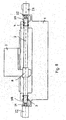
- Figs. 1 to 9 show drive systems which are designed as feed drives. With feed drives, for example, carriages are moved on machine tools.
- Fig. 1a shows such a machine with a machine bed 1, on which a spindle 2 is rotatably mounted.
- the spindle 2 is rotatably mounted in the machine bed with their ends 3, 4.
- the nut 5 is rotatable but axially non-displaceably mounted in the carriage 7.
- the feed drive 6 has a drive motor 9 with a drive shaft 10, rotatably on a pulley 11 is seated, over which an endless drive belt is guided. On the nut 5 also sits a pulley 13 for the drive belt 12. With the drive motor 9, the drive shaft 10 is rotated, the nut 5 rotatably drives on the described belt drive 11 to 13. Since it is in engagement with the rotationally fixed spindle 2, the nut 5 is displaced along the spindle 2, whereby the carriage 7 is displaced in the corresponding direction along the guide 8. Depending on the direction of rotation of the drive shaft 10, the carriage 7 is moved in the respective direction on the machine bed 1.
- a servo motor As a drive motor 9, a servo motor is used. Since the carriage 7 with the drive motor 9 has considerable weight, correspondingly strong drive motors 9 are required to accelerate the carriage quickly or decelerate.
- Fig. 1 b shows a known machine in which the spindle 2 is rotatably mounted on the machine bed 1. Your one end 3 is drivingly connected via a belt drive with a drive motor 22 attached to the machine bed 1. On the spindle 2 sits the nut 5, which is rotatably mounted in the carriage 7. By turning the spindle 2, the carriage 7 is moved over the nut 5 along the guide 8. With such a machine, high accelerations as well as rapid traverse and feed speeds can not be achieved.
- the nut 5 seated on the threaded spindle 2 is rotatably driven in the described manner via the belt drive 11 to 13.
- the drive motor 9, which is preferably a servomotor, is supported by the carriage 7.
- the nut 5 is rotatable but axially non-displaceably mounted in the carriage 7, the one has corresponding receiving space 14 for the nut 5 and bearing 15 for rotatably supporting the nut.
- the rotatably seated on the drive shaft 10 pulley 11 has a smaller diameter than the nut 5 rotatably seated pulley 13. This reduces the speed of the drive shaft 10 according to the diameter ratio of the two pulleys 11, 13.
- the carriage 7 is movable along the guide 8 on the machine bed 1.
- the spindle 2 is rotatably supported by its ends 3, 4 via bearings 16, 17 in the machine bed 1.
- a pulley 18 On one end of the spindle 2 rotatably seated a pulley 18 which is drivingly connected via a drive belt 19 with a pulley 20. It sits non-rotatably on a drive shaft 21 of a drive motor 22, which is advantageous as well as the drive motor 9 is a servo motor.
- the drive motor 22 is attached to the machine bed 1.
- the pulley is located in a recess 23 of the machine bed 1, in which the drive shaft 21 protrudes. Since the pulley 20 has smaller diameter than the spindle-side pulley 18, the rotational speed of the drive shaft 21 is reduced in the rotational speed of the threaded spindle 2.
- the nut 5 and the threaded spindle 2 are rotatably driven in opposite directions.
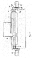
- the embodiment of FIG. 3 differs from the embodiment of FIG. 2 only in that the spindle 2 at both ends 3, 4, each with a drive motor 22, 24 is rotatably driven.
- the drive motor 24 is flanged on the machine bed 1 and has a drive shaft 25, on which a pulley 26 is seated, which rotatably via a drive belt 27 with a on the spindle 2 seated pulley 28 is drivingly connected.
- the pulley 26 has like the pulley 20 half the diameter of the pulley 28.
- the two motors 22, 24 are driven synchronously and are advantageously in a control loop, so that the rotational speeds of the two motors 22, 24 can be matched exactly. Since the spindle 2 is driven at both ends, the drive motors 22, 24 do not require high torque, so that they can be designed to be compact.
- the embodiment of FIG. 3 is the same design as the embodiment of FIG. 2nd
- 4 and 5 show the possibility of rotatably driving the nut 5 seated on the threaded spindle 2 with two drive motors 29, 30, but instead of supporting the threaded spindle 2 in the machine bed 1 in a rotationally fixed manner.
- the nut 5 is rotatably driven only by a respective drive motor 9, but also to drive the threaded spindle 2 rotatably.
- the two drive motors 29, 30 are superimposed on one side of the spindle 2 and the nut 5.
- the drive motors 29, 30 have mutually parallel drive shafts 31, 32, on each of which a pulley 33, 34 rotatably seated. They advantageously have the same diameter and are drive-connected to one another via an endlessly circulating drive belt 35.
- On the nut 5 sits the pulley 13, which is wrapped by the drive belt 35.
- On the side facing away from the pulley 13 is located in the region between the pulleys 33, 34 a tension roller 36, with the necessary voltage of the drive belt 35 can be adjusted.
- the tension roller 36 is advantageously transverse to the axis of the spindle 2 and the nut 5 adjustable.
- the drive motors 29, 30 and the tension roller 36 are mounted on the carriage 7 ( Figures 2 and 3).
- the pulleys 33, 34 lie in a common radial plane of the spindle 2 and the nut 5.
- FIGS. 6 and 7 show an embodiment in which the pulleys 33, 34 of the drive motors 29, 30 are axially offset from each other.
- two drive belts 35 and 37 are necessary to rotatably drive the nut 5.
- the drive belt 35, 37 are adjacent to each other with a small axial distance. Accordingly, the nut 5 is wider than in the previous embodiments, in which only a single drive belt 12, 35 is provided for driving the nut 5.
- the strands of the two drive belts 35, 37 cross each other.
- the two drive motors 29, 30 are advantageously the same design and have the same characteristic. It is of course possible to use drive motors 29, 30 of different design and / or different characteristics. In this case, it is advantageously ensured by means of a regulation that the two drive motors 29, 30 are matched in their rotational speed to one another in order to reliably drive the nut 5 rotatably.
- the nut 5 is rotatably driven by the one drive motor 9 and the spindle 2 by one (FIG. 2) or by two drive motors 22, 24 (FIG. 3).
- the drive motors 9, 22, 24 for driving the nut 5 and the spindle 2 are connected to each other synchronized and thus have the same speed.
- the thus released engine torque allows to exert a correspondingly high axial force on the carriage 7 and to achieve a higher acceleration. If the nut 5 and the spindle 2 are rotatably driven separately from each other, the pulleys on the drive shafts 10, 21, 25 of the drive motors 9, 22, 24 may be small, so that there are only correspondingly small moment of inertia. As a result, acceleration increases compared to the conventional feed drives of about 20 to 30% are possible.
- Fig. 8 shows an embodiment in which the nut 5 is rotatably mounted in the carriage 7.
- the spindle 2 is rotatably driven at its two ends 3 and 4 with the drive motors 22, 24.
- the drive of the spindle 2 without translation, but directly.
- the two drive shafts 21, 25 of the drive motors 22, 24 are rotatably connected to the spindle ends 3, 4 via a respective coupling piece 38, 39.
- the two drive motors 22, 24 are advantageously the same design and have the same characteristic. Of course, it is possible to use drive motors 22, 24 of different design and / or different characteristics.
- FIG. 9 differs from the embodiment of FIG. 3 only in that the nut. 5 is not rotatably driven and rotatably seated in the carriage 7.
- the spindle is rotatably driven via the two drive motors 22, 24 via a belt transmission. Even with such an embodiment, very high accelerations and, correspondingly, high positioning speeds are achieved.
- the resulting feed rate of the carriage 7 can be controlled in the described embodiments by selecting the parameters direction of rotation and rotational speed in an additive or subtractive sense. If the threaded spindle 2 and the nut 5 are driven in the opposite direction to each other at the same speed, the carriage 7 stops. If, however, the threaded spindle 2 and the nut 5 are rotatably driven at different speeds, the carriage 7 moves on the machine bed 1. Depending on the difference in rotational speeds, a corresponding feed speed of the carriage 7 is achieved.
- the carriage movement from standstill can be initiated by the threaded spindle 2 and the nut 5 are first brought in the same direction rotating to the optimum speed. Subsequently, one of the drive motors is brought to a standstill with a high delay and then optionally accelerated again in the gene direction. In this way, the moment of inertia for driving the carriage 7 can be utilized.
- two screw drives each consisting of a threaded spindle and a nut, connected in series.
- the two nuts are each connected to a carriage. Both sleds have a common leadership.
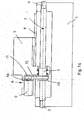
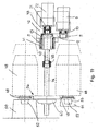
- Figs. 10 to 15 show a drive with which a rapid tool change can be made.
- the drive has a threaded spindle 40, which is advantageously a ball screw.
- the nut 5 On it sits the nut 5, which is rotatably mounted in a housing 41. It is fixedly connected to a carrier 42, which receives the horizontal guide rail 8 (Fig. 10) for the carriage 7.
- the threaded spindle 40 is rotatably connected at one end via a coupling 43 to the drive shaft 21 of the drive motor 22.
- the drive motor 22 is, as shown in FIG. 10, mounted on the carriage 7.
- the threaded spindle 40 is rotatably connected to a lying flush with her shaft 44 via a clutch 45.
- the shaft 44 is rotatably supported in a machine-fixed support bearing 60 and axially displaceable.
- Two grippers 46 and 47 of a gripper device 56 which can be switched on and exchanged with the tools 48, are non-rotatably mounted on the shaft 44.
- the grippers 46, 47 are the same and, as shown in FIG. 10, rotated by 180 ° to each other.
- the grippers 46, 47 engage in gripping grooves 49 of the tools 48 a.
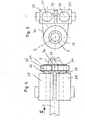
- 10 shows the two grippers 46, 47 in the gripping position, in which they grasp the tool 48 located in a machine spindle 50 and the tool 48 located in a magazine place 51.
- Both tools 48 have a cone 52, with which they engage in the machine spindle 50 and in a corresponding receptacle 53 in the magazine slot 51.
- To replace the tools 48 they must first be moved axially so that their cones 52 come free from the machine spindle 50 and from the receptacle 53 of the magazine place 51.
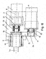
- the nut 5 protrudes toward the drive motor 22 via the housing 41.
- This projecting end is in turn formed as a pulley 13, which is connected via the drive belt 12 with the pulley 11 on the drive shaft 10 of the drive motor 9.
- the drive motor 9 is parallel to the drive motor 22 and is fixed to the carrier 42.
- the two drive motors 9, 22 are, seen in the axial direction of the shaft 44, one above the other.
- the pulley 13 is clamped on the drive shaft 10 by means of a clamping device 55 by means of a bushing 54, which is advantageously integrally formed with the pulley.
- the nut 5 is driven by means of the drive motor 9 and the belt drive 11 to 13 in the required direction.
- the threaded spindle 40 is thereby displaced axially, but not rotated about its axis.
- the drive motor 22 is moved over the carriage 7 along the guide 8. Since the threaded spindle 40 is non-rotatably and axially fixedly connected to the shaft 44, thus the gripping device 56 having the two grippers 46, 47 is also displaced axially. In this case, the grippers 46, 47 take the tools 48 so far in the described manner until the cones 52 come free from the machine spindle 50 or from the magazine position 51.
- the drive motor 22 is turned on and the threaded spindle 40 is driven in the required direction of rotation.
- the shaft 44 is rotated with the gripping device 56.
- the nut 5 is driven by the drive motor 9 in the same direction as the threaded spindle 40.
- the drive of the nut 5 and the threaded spindle 40 is, as has been described by way of example with reference to FIG. 2, coordinated so that the threaded spindle 40 is rotated only about its axis, but not axially displaced.
- the gripping device 56 is rotated about the axis of the shaft 44, whereby the tools 48 exchange their places.
- the drive motor 22 is switched off and the drive motor 9 is switched over, so that the nut 5 is driven in the reverse direction of rotation. Since the threaded spindle 40 is stationary, the tools 48 are inserted into the machine spindle 50 or into the magazine slot 51.
- the tools 48 are provided with the cones 52, it is possible to use the axial movement and the rotational movement in combination, so that the tool 48 is already pivoted out of the machine spindle 50 or out of the magazine position 51 when the cone 52 is moved out.
- the cone 52 of the tools 48 has been pulled out slightly axially, it has a distance from the wall of the cone holder of the machine spindle 50 or the magazine position 51. Therefore, the tool 48 can already be rotated in accordance with the cone angle when moving out.
- the control must only be tuned so that the cone 52 does not touch the wall of the receptacles in the machine spindle 50 and magazine slot 51 during this pivoting movement.
- the drive motor 9 is turned on, so that the axially immovable nut 5 is rotated in the required sense.
- the threaded spindle 40 and the shaft 44 are displaced axially and thereby the respective tool 48 is pulled out of the machine spindle 50 and out of the magazine position 51.
- the drive motor 22 is turned on to rotate the threaded spindle 40 and the shaft 44 during its axial movement, depending on the cone angle.
- the two drive motors 9 and 22 are coupled together via a control, so that as the cone 52 is pulled out of the machine spindle 50 and from the receptacle 53 of the magazine place 51, is also pivoted.
- the drive motors 9, 22 are driven via the controller so that the threaded spindle 40 is rotated only, but not axially displaced.
- the nut 5 is rotatably driven in the manner described in the opposite direction to the threaded spindle 40.
- the gripper 56 is then rotated about the axis of the shaft 44, as previously described, so that the tools 48 engaged by the grippers 46, 47 exchange places.
- the drive motors 9 and 22 are switched so that the tools 48 are again axially displaced in the direction of the machine spindle 50 and the free magazine position 51.
- the drive motors 9, 22 are matched to one another via the control, that during this axial movement and a rotational movement of the threaded spindle 40 and the shaft 44 takes place.
- the linear movement is thus superimposed on the rotational movement as a function of the cone angle of the cones 52 of the tools 58.
- the drive motor 22 Shortly before reaching the end position of the cones 52, the drive motor 22 is turned off, so that only the nut 5 is driven by the motor 9.
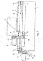
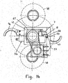
- the described sequence of movements can also, as shown in FIG. 14, be supplemented by approaching an intermediate, waiting or parking position of the grippers 46, 47 of the gripping device 56.
- the two grippers 46, 47 are in the gripping position, in which they engage in the gripper grooves 49 of the tools 48.
- the grippers 46, 47 can be axially displaced and pivoted in the manner described with reference to FIGS. 10 to 12 in order to load the tools in the machine spindle 50 and in the magazine place 51.
- the gripping device 56 is pivoted empty by 90 ° in the intermediate, waiting or parking position shown in Fig. 14. In this intermediate position give the two grippers 46, 47, the machine spindle 50 and the magazine slot 51 free. If necessary, the grippers 46, 47 are again pivoted by 90 ° in the manner described in the tool transfer positions,
- FIG. 13 and 14 show two different variants for guiding the motor 22 mounted on a carrier angle 61. While the solution known from FIG. 10 is shown above the line of symmetry, a torque support of the carrier angle 61 which can be displaced in the axial direction is shown below.
- the torque support is formed by a recess extending in the direction of displacement of the threaded spindle 40 57 realized, in which a carriage 7 rotatably mounted support roller 58 engages.
- the drive according to FIGS. 13 and 14 is of the same design as the embodiment according to FIGS. 10 to 12.
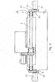
- FIG. 15 shows an embodiment in which the receptacle 53 of the magazine place 51 is axially reset relative to the receptacle of the machine spindle 50. Therefore, when the tool 48 is inserted into the machine spindle 50 with one gripper 46, the tool 48 gripped by the other gripper 47 is still engaged axial distance to the magazine location 51 (FIG. 15).
- 15 is suitable for a tool change in different, preferably to the axis of the threaded spindle 40 upper delivery levels both in terms of spindle level and magazine level. This is required on the one hand when equipping work spindles 50 with different spindle neck lengths and / or spindle heads that can be exchanged into the machine.
- the magazine side for example, by different magazine positions and / or different lengths tools, change the transfer position.
- the gripping device 56 is rotated by driving the nut 5 and the threaded spindle 40 about the axis of the threaded spindle 40 until the gripper 47 with its tool 48 of the receptacle 53 of the magazine slot 51 is opposite. Then, as has been described with reference to FIGS. 10 to 12, the tool 48 is inserted by axial displacement of the threaded spindle 40 in the receptacle 53 of the magazine slot 51.
- the two grippers 46, 47 of the gripping device 56 are of course arranged so that they do not collide with .
- the support bearing 60 is arranged for the shaft 44 at a greater distance from the carrier 42 than in the embodiment according to FIGS. 10 to 12.
- FIGS. 10 to 15 has been described advantageously for use in a gripping device. Moreover, such a drive can also be used where linear movements and rotary or pivoting movements have to be carried out both simultaneously and sequentially, for example pallet changers on machine tools. Such movements are necessary for items that must be moved or transported for manufacturing, storage, handling and the like.
Landscapes
- Engineering & Computer Science (AREA)
- Mechanical Engineering (AREA)
- Automatic Tool Replacement In Machine Tools (AREA)
- Transmission Devices (AREA)
- Manipulator (AREA)
- Feeding Of Workpieces (AREA)
- Vehicle Body Suspensions (AREA)
- Power Steering Mechanism (AREA)
- Multi-Process Working Machines And Systems (AREA)
- Turning (AREA)
Claims (10)
- Entraînement pour ensembles de serrage (56) avec au moins une broche filetée (40) qui peut être entrainée par un moteur de commande (22) et sur laquelle est placé au moins un écrou (5) lequel peut être entrainé rotativement à l'aide d'un moteur de commande (9) supplémentaire, l'ensemble de serrage (56) étant mobile axialement par un mouvement rotatif relatif entre la broche filetée (40) et l'écrou (5),
caractérisé en ce que l'ensemble de serrage (56) est monté de façon solidaire en rotation sur un arbre (44) ,celui-ci étant connecté de façon solidaire en rotation avec la broche filetée (40) et pouvant être tourné par actionnement du moteur de commande (9, 22) autour de l'axe de la broche filetée (40). - Entraînement selon revendication 1,
caractérisé en ce que des outils (48) peuvent être maniés avec l'ensemble de serrage (56). - Entraînement selon revendication 2,
caractérisé en ce que les outils (48) ont un cône. - Entraînement selon revendication 3,
caractérisé en ce que l'ensemble de serrage (56) est un élément d'un changeur d'outil. - Entraînement selon une des revendications 1 à 4,
caractérisé en ce que l'ensemble de serrage (56) est ajustable à une position intermédiaire dans laquelle les preneurs (46, 47) sont placés hors des positions de transfert d'outil. - Entraînement selon une des revendications 1 à 5,
caractérisé en ce que l'ensemble de serrage (56) est déplaçable en direction de l'axe de la broche filetée (40) après le remplacement d'un certain outil (48) par introduction ou sortie pour le remplacement de celui-ci par l'autre outil (48) par introduction ou sortie. - Entraînement selon revendication 6,
caractérisé en ce que le moteur de commande (22) entraînant la broche filetée (40) est déplaçable avec un chariot (7) le long d'un guidage (8). - Entraînement selon une des revendications 3 à 7,
caractérisé en ce que la superposition du mouvement axial et du mouvement rotatif de la broche filetée (40) a lieu en dépendance de l'angle de cône des cônes (52) des outils (48). - Entraînement selon une des revendications 1 à 8,
caractérisé en ce que l'arbre (50) recevant l'outil (48) maintient sa position durant le changement d'outil. - Procédé pour l'actionnement d'un ensemble de serrage (56) selon une des revendications 1 à 9, étant connecté avec l'entraînement d'une broche filetée (40) et dans lequel un écrou (5) monté sur la broche filetée (40) est entraîné de façon rotative par un moteur de commande (9) et dans lequel la broche filetée (40) est entraîné de façon rotative par un moteur de commande supplémentaire (22) et dans lequel l'ensemble de serrage (56) est déplacé dans une position axiale par une rotation relative entre l'écrou (5) et la broche filetée (40) et dans lequel l'écrou (5) et la broche filetée (40) sont entraînés simultanément et de façon rotative après ralliement à la position axiale de l'ensemble de serrage (56) de sorte que l'ensemble de serrage (56) tourne dans sa position axiale.
Applications Claiming Priority (3)
| Application Number | Priority Date | Filing Date | Title |
|---|---|---|---|
| DE19859881 | 1998-12-23 | ||
| DE19859881A DE19859881A1 (de) | 1998-12-23 | 1998-12-23 | Vorschubantrieb, insbesondere für Schlitten von Maschinen |
| EP99125297A EP1013373B1 (fr) | 1998-12-23 | 1999-12-20 | Entraínement pour unités de machines, par exemple chariots, ensembles de serrage ou similaires |
Related Parent Applications (1)
| Application Number | Title | Priority Date | Filing Date |
|---|---|---|---|
| EP99125297A Division EP1013373B1 (fr) | 1998-12-23 | 1999-12-20 | Entraínement pour unités de machines, par exemple chariots, ensembles de serrage ou similaires |
Publications (2)
| Publication Number | Publication Date |
|---|---|
| EP1525945A1 EP1525945A1 (fr) | 2005-04-27 |
| EP1525945B1 true EP1525945B1 (fr) | 2007-07-11 |
Family
ID=7892551
Family Applications (2)
| Application Number | Title | Priority Date | Filing Date |
|---|---|---|---|
| EP05000875A Expired - Lifetime EP1525945B1 (fr) | 1998-12-23 | 1999-12-20 | Entraînement pour ensembles de serrage |
| EP99125297A Expired - Lifetime EP1013373B1 (fr) | 1998-12-23 | 1999-12-20 | Entraínement pour unités de machines, par exemple chariots, ensembles de serrage ou similaires |
Family Applications After (1)
| Application Number | Title | Priority Date | Filing Date |
|---|---|---|---|
| EP99125297A Expired - Lifetime EP1013373B1 (fr) | 1998-12-23 | 1999-12-20 | Entraínement pour unités de machines, par exemple chariots, ensembles de serrage ou similaires |
Country Status (3)
| Country | Link |
|---|---|
| EP (2) | EP1525945B1 (fr) |
| AT (2) | ATE292541T1 (fr) |
| DE (3) | DE19859881A1 (fr) |
Cited By (1)
| Publication number | Priority date | Publication date | Assignee | Title |
|---|---|---|---|---|
| DE102019115715A1 (de) * | 2019-06-11 | 2020-12-17 | Gebr. Heller Maschinenfabrik Gmbh | Wechselvorrichtung zum Auswechseln von Werkzeugen und/oder Werkstücken |
Families Citing this family (7)
| Publication number | Priority date | Publication date | Assignee | Title |
|---|---|---|---|---|
| DE10117948A1 (de) | 2001-04-10 | 2002-10-17 | Heller Geb Gmbh Maschf | Antrieb für Maschinenaggregate, wie Schlitten, Greifeinrichtungen u. dgl. |
| DE102005054290A1 (de) * | 2005-11-11 | 2007-05-16 | Bosch Rexroth Mechatronics | Schnell verfahrender Gewindetrieb |
| CN101758392B (zh) * | 2008-12-10 | 2012-01-25 | 抚顺煤矿电机制造有限责任公司 | 一种通用内水套车床胎具 |
| DE102012203553A1 (de) * | 2012-03-07 | 2013-09-26 | Zf Friedrichshafen Ag | Übersetzungsgetriebe |
| DE102012103819A1 (de) * | 2012-05-02 | 2013-11-07 | Zf Lenksysteme Gmbh | Kugelgewindetrieb |
| TWI650201B (zh) * | 2018-07-06 | 2019-02-11 | 聖杰國際股份有限公司 | 自動換刀機構之換刀控制方法 |
| TWI655993B (zh) * | 2018-07-06 | 2019-04-11 | 聖杰國際股份有限公司 | Shaft rotation and linear displacement control system and automatic tool change mechanism having the same |
Family Cites Families (5)
| Publication number | Priority date | Publication date | Assignee | Title |
|---|---|---|---|---|
| JPS5857557A (ja) * | 1981-10-01 | 1983-04-05 | Kiriyuu Kikai Kk | 直線往復運動装置 |
| CH647305A5 (en) * | 1981-12-18 | 1985-01-15 | Hans Fickler | Linear push device |
| JPS58118361A (ja) * | 1981-12-29 | 1983-07-14 | Hiroshi Teramachi | ボ−ルねじユニツトを用いた移送装置 |
| AU6653294A (en) * | 1992-12-08 | 1994-07-04 | Licexia, Spolecnost S Rucenim Omezenym | Power gear assembly |
| JPH09201629A (ja) * | 1996-01-16 | 1997-08-05 | Amada Mfg America Inc | 板材加工機のワーク送り装置およびこれを用いた板材加工機 |
-
1998
- 1998-12-23 DE DE19859881A patent/DE19859881A1/de not_active Withdrawn
-
1999
- 1999-12-20 DE DE59914410T patent/DE59914410D1/de not_active Expired - Lifetime
- 1999-12-20 AT AT99125297T patent/ATE292541T1/de not_active IP Right Cessation
- 1999-12-20 DE DE59911872T patent/DE59911872D1/de not_active Expired - Lifetime
- 1999-12-20 AT AT05000875T patent/ATE366635T1/de not_active IP Right Cessation
- 1999-12-20 EP EP05000875A patent/EP1525945B1/fr not_active Expired - Lifetime
- 1999-12-20 EP EP99125297A patent/EP1013373B1/fr not_active Expired - Lifetime
Cited By (1)
| Publication number | Priority date | Publication date | Assignee | Title |
|---|---|---|---|---|
| DE102019115715A1 (de) * | 2019-06-11 | 2020-12-17 | Gebr. Heller Maschinenfabrik Gmbh | Wechselvorrichtung zum Auswechseln von Werkzeugen und/oder Werkstücken |
Also Published As
| Publication number | Publication date |
|---|---|
| ATE292541T1 (de) | 2005-04-15 |
| DE19859881A1 (de) | 2000-06-29 |
| EP1525945A1 (fr) | 2005-04-27 |
| ATE366635T1 (de) | 2007-08-15 |
| EP1013373A3 (fr) | 2002-12-04 |
| DE59911872D1 (de) | 2005-05-12 |
| EP1013373A2 (fr) | 2000-06-28 |
| DE59914410D1 (de) | 2007-08-23 |
| EP1013373B1 (fr) | 2005-04-06 |
Similar Documents
| Publication | Publication Date | Title |
|---|---|---|
| EP1982799B1 (fr) | Agencement de manipulation | |
| EP0968069B2 (fr) | Machine-outil | |
| EP3444931B1 (fr) | Bobineuse | |
| CH661222A5 (de) | Mehrspindel-drehautomat. | |
| DE3722643C1 (de) | Werkzeugrevolver | |
| EP0693334B1 (fr) | Système de transport | |
| WO2000054904A1 (fr) | Systeme de transport | |
| CH631097A5 (de) | Werkzeugmaschine. | |
| DE2904088C2 (de) | Be- und/oder Entladeeinrichtung für Werkzeugmaschinen, insbesondere Drehautomaten | |
| DE3722180C2 (de) | Transfermaschine | |
| EP1525945B1 (fr) | Entraînement pour ensembles de serrage | |
| DE4430389C2 (de) | Selbstladende Vertikaldrehmaschine | |
| EP0745453B1 (fr) | Chargeur et déchargeur | |
| DE3745008C2 (fr) | ||
| EP3016760B1 (fr) | Dispositif et procédé pour transférer un élément et système d'outil | |
| EP3159068B1 (fr) | Banc de formage de pression/d'emboutissage et procede de pression/d'emboutissage | |
| EP0180050A1 (fr) | Dispositif d'entraînement pour porte-pièces de machines d'usinage | |
| DE4035353A1 (de) | Nutenstanzanlage | |
| EP1249306A1 (fr) | Entraínement pour unités de machines, par example chariots, ensembles de serrage ou similaires | |
| DE19701007B4 (de) | Werkstückzuführvorrichtung und Werkzeugmaschine | |
| DE4036449A1 (de) | Mehrfachspindel-stangenbearbeitungsmaschine | |
| EP0358928B1 (fr) | Machine-outil | |
| DE2349700B2 (de) | Einspindelstangenlangdrehautomat | |
| DE19600054C2 (de) | Werkzeugmaschine mit gemeinsamem Hub- und Wechslerantrieb | |
| DE19504370A1 (de) | Mehrspindeldrehmaschine |
Legal Events
| Date | Code | Title | Description |
|---|---|---|---|
| PUAI | Public reference made under article 153(3) epc to a published international application that has entered the european phase |
Free format text: ORIGINAL CODE: 0009012 |
|
| AC | Divisional application: reference to earlier application |
Ref document number: 1013373 Country of ref document: EP Kind code of ref document: P |
|
| AK | Designated contracting states |
Kind code of ref document: A1 Designated state(s): AT BE CH CY DE DK ES FI FR GB GR IE IT LI LU MC NL PT SE |
|
| 17P | Request for examination filed |
Effective date: 20051020 |
|
| AKX | Designation fees paid |
Designated state(s): AT BE CH CY DE DK ES FI FR GB GR IE IT LI LU MC NL PT SE |
|
| 17Q | First examination report despatched |
Effective date: 20060207 |
|
| GRAP | Despatch of communication of intention to grant a patent |
Free format text: ORIGINAL CODE: EPIDOSNIGR1 |
|
| RTI1 | Title (correction) |
Free format text: DRIVE FOR GRIPPING DEVICES |
|
| GRAS | Grant fee paid |
Free format text: ORIGINAL CODE: EPIDOSNIGR3 |
|
| GRAA | (expected) grant |
Free format text: ORIGINAL CODE: 0009210 |
|
| AC | Divisional application: reference to earlier application |
Ref document number: 1013373 Country of ref document: EP Kind code of ref document: P |
|
| AK | Designated contracting states |
Kind code of ref document: B1 Designated state(s): AT BE CH CY DE DK ES FI FR GB GR IE IT LI LU MC NL PT SE |
|
| REG | Reference to a national code |
Ref country code: GB Ref legal event code: FG4D Free format text: NOT ENGLISH |
|
| REG | Reference to a national code |
Ref country code: CH Ref legal event code: EP |
|
| REF | Corresponds to: |
Ref document number: 59914410 Country of ref document: DE Date of ref document: 20070823 Kind code of ref document: P |
|
| REG | Reference to a national code |
Ref country code: IE Ref legal event code: FG4D Free format text: LANGUAGE OF EP DOCUMENT: GERMAN |
|
| PG25 | Lapsed in a contracting state [announced via postgrant information from national office to epo] |
Ref country code: PT Free format text: LAPSE BECAUSE OF FAILURE TO SUBMIT A TRANSLATION OF THE DESCRIPTION OR TO PAY THE FEE WITHIN THE PRESCRIBED TIME-LIMIT Effective date: 20071211 Ref country code: FI Free format text: LAPSE BECAUSE OF FAILURE TO SUBMIT A TRANSLATION OF THE DESCRIPTION OR TO PAY THE FEE WITHIN THE PRESCRIBED TIME-LIMIT Effective date: 20070711 Ref country code: NL Free format text: LAPSE BECAUSE OF FAILURE TO SUBMIT A TRANSLATION OF THE DESCRIPTION OR TO PAY THE FEE WITHIN THE PRESCRIBED TIME-LIMIT Effective date: 20070711 Ref country code: ES Free format text: LAPSE BECAUSE OF FAILURE TO SUBMIT A TRANSLATION OF THE DESCRIPTION OR TO PAY THE FEE WITHIN THE PRESCRIBED TIME-LIMIT Effective date: 20071022 |
|
| NLV1 | Nl: lapsed or annulled due to failure to fulfill the requirements of art. 29p and 29m of the patents act | ||
| GBV | Gb: ep patent (uk) treated as always having been void in accordance with gb section 77(7)/1977 [no translation filed] |
Effective date: 20070711 |
|
| REG | Reference to a national code |
Ref country code: IE Ref legal event code: FD4D |
|
| EN | Fr: translation not filed | ||
| PG25 | Lapsed in a contracting state [announced via postgrant information from national office to epo] |
Ref country code: DK Free format text: LAPSE BECAUSE OF FAILURE TO SUBMIT A TRANSLATION OF THE DESCRIPTION OR TO PAY THE FEE WITHIN THE PRESCRIBED TIME-LIMIT Effective date: 20070711 Ref country code: GR Free format text: LAPSE BECAUSE OF FAILURE TO SUBMIT A TRANSLATION OF THE DESCRIPTION OR TO PAY THE FEE WITHIN THE PRESCRIBED TIME-LIMIT Effective date: 20071012 |
|
| PLBE | No opposition filed within time limit |
Free format text: ORIGINAL CODE: 0009261 |
|
| STAA | Information on the status of an ep patent application or granted ep patent |
Free format text: STATUS: NO OPPOSITION FILED WITHIN TIME LIMIT |
|
| PG25 | Lapsed in a contracting state [announced via postgrant information from national office to epo] |
Ref country code: GB Free format text: LAPSE BECAUSE OF FAILURE TO SUBMIT A TRANSLATION OF THE DESCRIPTION OR TO PAY THE FEE WITHIN THE PRESCRIBED TIME-LIMIT Effective date: 20070711 Ref country code: IE Free format text: LAPSE BECAUSE OF FAILURE TO SUBMIT A TRANSLATION OF THE DESCRIPTION OR TO PAY THE FEE WITHIN THE PRESCRIBED TIME-LIMIT Effective date: 20070711 |
|
| 26N | No opposition filed |
Effective date: 20080414 |
|
| BERE | Be: lapsed |
Owner name: GEBR. HELLER MASCHINENFABRIK G.M.B.H. Effective date: 20071231 |
|
| PG25 | Lapsed in a contracting state [announced via postgrant information from national office to epo] |
Ref country code: SE Free format text: LAPSE BECAUSE OF FAILURE TO SUBMIT A TRANSLATION OF THE DESCRIPTION OR TO PAY THE FEE WITHIN THE PRESCRIBED TIME-LIMIT Effective date: 20071011 |
|
| PG25 | Lapsed in a contracting state [announced via postgrant information from national office to epo] |
Ref country code: FR Free format text: LAPSE BECAUSE OF FAILURE TO SUBMIT A TRANSLATION OF THE DESCRIPTION OR TO PAY THE FEE WITHIN THE PRESCRIBED TIME-LIMIT Effective date: 20080307 Ref country code: MC Free format text: LAPSE BECAUSE OF NON-PAYMENT OF DUE FEES Effective date: 20071231 |
|
| REG | Reference to a national code |
Ref country code: CH Ref legal event code: PL |
|
| PG25 | Lapsed in a contracting state [announced via postgrant information from national office to epo] |
Ref country code: BE Free format text: LAPSE BECAUSE OF NON-PAYMENT OF DUE FEES Effective date: 20071231 |
|
| PG25 | Lapsed in a contracting state [announced via postgrant information from national office to epo] |
Ref country code: LI Free format text: LAPSE BECAUSE OF NON-PAYMENT OF DUE FEES Effective date: 20071231 Ref country code: CH Free format text: LAPSE BECAUSE OF NON-PAYMENT OF DUE FEES Effective date: 20071231 |
|
| PG25 | Lapsed in a contracting state [announced via postgrant information from national office to epo] |
Ref country code: AT Free format text: LAPSE BECAUSE OF NON-PAYMENT OF DUE FEES Effective date: 20071220 |
|
| PG25 | Lapsed in a contracting state [announced via postgrant information from national office to epo] |
Ref country code: CY Free format text: LAPSE BECAUSE OF FAILURE TO SUBMIT A TRANSLATION OF THE DESCRIPTION OR TO PAY THE FEE WITHIN THE PRESCRIBED TIME-LIMIT Effective date: 20070711 |
|
| PG25 | Lapsed in a contracting state [announced via postgrant information from national office to epo] |
Ref country code: LU Free format text: LAPSE BECAUSE OF NON-PAYMENT OF DUE FEES Effective date: 20071220 |
|
| PG25 | Lapsed in a contracting state [announced via postgrant information from national office to epo] |
Ref country code: IT Free format text: LAPSE BECAUSE OF NON-PAYMENT OF DUE FEES Effective date: 20091220 |
|
| PGRI | Patent reinstated in contracting state [announced from national office to epo] |
Ref country code: IT Effective date: 20110616 |
|
| PGFP | Annual fee paid to national office [announced via postgrant information from national office to epo] |
Ref country code: IT Payment date: 20181130 Year of fee payment: 20 |
|
| PGFP | Annual fee paid to national office [announced via postgrant information from national office to epo] |
Ref country code: DE Payment date: 20190225 Year of fee payment: 20 |
|
| REG | Reference to a national code |
Ref country code: DE Ref legal event code: R071 Ref document number: 59914410 Country of ref document: DE |