EP1525918A2 - Experimentiervorrichtung und Verfahren - Google Patents
Experimentiervorrichtung und Verfahren Download PDFInfo
- Publication number
- EP1525918A2 EP1525918A2 EP04022137A EP04022137A EP1525918A2 EP 1525918 A2 EP1525918 A2 EP 1525918A2 EP 04022137 A EP04022137 A EP 04022137A EP 04022137 A EP04022137 A EP 04022137A EP 1525918 A2 EP1525918 A2 EP 1525918A2
- Authority
- EP
- European Patent Office
- Prior art keywords
- cannulas
- experimental chamber
- chamber
- septa
- interface
- Prior art date
- Legal status (The legal status is an assumption and is not a legal conclusion. Google has not performed a legal analysis and makes no representation as to the accuracy of the status listed.)
- Granted
Links
Images


Classifications
-
- G—PHYSICS
- G01—MEASURING; TESTING
- G01N—INVESTIGATING OR ANALYSING MATERIALS BY DETERMINING THEIR CHEMICAL OR PHYSICAL PROPERTIES
- G01N35/00—Automatic analysis not limited to methods or materials provided for in any single one of groups G01N1/00 - G01N33/00; Handling materials therefor
- G01N35/10—Devices for transferring samples or any liquids to, in, or from, the analysis apparatus, e.g. suction devices, injection devices
- G01N35/1079—Devices for transferring samples or any liquids to, in, or from, the analysis apparatus, e.g. suction devices, injection devices with means for piercing stoppers or septums
-
- B—PERFORMING OPERATIONS; TRANSPORTING
- B01—PHYSICAL OR CHEMICAL PROCESSES OR APPARATUS IN GENERAL
- B01L—CHEMICAL OR PHYSICAL LABORATORY APPARATUS FOR GENERAL USE
- B01L3/00—Containers or dishes for laboratory use, e.g. laboratory glassware; Droppers
- B01L3/50—Containers for the purpose of retaining a material to be analysed, e.g. test tubes
- B01L3/502—Containers for the purpose of retaining a material to be analysed, e.g. test tubes with fluid transport, e.g. in multi-compartment structures
- B01L3/5027—Containers for the purpose of retaining a material to be analysed, e.g. test tubes with fluid transport, e.g. in multi-compartment structures by integrated microfluidic structures, i.e. dimensions of channels and chambers are such that surface tension forces are important, e.g. lab-on-a-chip
- B01L3/502715—Containers for the purpose of retaining a material to be analysed, e.g. test tubes with fluid transport, e.g. in multi-compartment structures by integrated microfluidic structures, i.e. dimensions of channels and chambers are such that surface tension forces are important, e.g. lab-on-a-chip characterised by interfacing components, e.g. fluidic, electrical, optical or mechanical interfaces
-
- B—PERFORMING OPERATIONS; TRANSPORTING
- B01—PHYSICAL OR CHEMICAL PROCESSES OR APPARATUS IN GENERAL
- B01L—CHEMICAL OR PHYSICAL LABORATORY APPARATUS FOR GENERAL USE
- B01L3/00—Containers or dishes for laboratory use, e.g. laboratory glassware; Droppers
- B01L3/56—Labware specially adapted for transferring fluids
- B01L3/563—Joints or fittings; Separable fluid transfer means to transfer fluids between at least two containers, e.g. connectors
-
- B—PERFORMING OPERATIONS; TRANSPORTING
- B01—PHYSICAL OR CHEMICAL PROCESSES OR APPARATUS IN GENERAL
- B01L—CHEMICAL OR PHYSICAL LABORATORY APPARATUS FOR GENERAL USE
- B01L2200/00—Solutions for specific problems relating to chemical or physical laboratory apparatus
- B01L2200/02—Adapting objects or devices to another
- B01L2200/026—Fluid interfacing between devices or objects, e.g. connectors, inlet details
-
- B—PERFORMING OPERATIONS; TRANSPORTING
- B01—PHYSICAL OR CHEMICAL PROCESSES OR APPARATUS IN GENERAL
- B01L—CHEMICAL OR PHYSICAL LABORATORY APPARATUS FOR GENERAL USE
- B01L2200/00—Solutions for specific problems relating to chemical or physical laboratory apparatus
- B01L2200/02—Adapting objects or devices to another
- B01L2200/028—Modular arrangements
-
- B—PERFORMING OPERATIONS; TRANSPORTING
- B01—PHYSICAL OR CHEMICAL PROCESSES OR APPARATUS IN GENERAL
- B01L—CHEMICAL OR PHYSICAL LABORATORY APPARATUS FOR GENERAL USE
- B01L2200/00—Solutions for specific problems relating to chemical or physical laboratory apparatus
- B01L2200/04—Exchange or ejection of cartridges, containers or reservoirs
-
- B—PERFORMING OPERATIONS; TRANSPORTING
- B01—PHYSICAL OR CHEMICAL PROCESSES OR APPARATUS IN GENERAL
- B01L—CHEMICAL OR PHYSICAL LABORATORY APPARATUS FOR GENERAL USE
- B01L2300/00—Additional constructional details
- B01L2300/04—Closures and closing means
- B01L2300/041—Connecting closures to device or container
- B01L2300/044—Connecting closures to device or container pierceable, e.g. films, membranes
-
- B—PERFORMING OPERATIONS; TRANSPORTING
- B01—PHYSICAL OR CHEMICAL PROCESSES OR APPARATUS IN GENERAL
- B01L—CHEMICAL OR PHYSICAL LABORATORY APPARATUS FOR GENERAL USE
- B01L2300/00—Additional constructional details
- B01L2300/06—Auxiliary integrated devices, integrated components
- B01L2300/0672—Integrated piercing tool
-
- B—PERFORMING OPERATIONS; TRANSPORTING
- B01—PHYSICAL OR CHEMICAL PROCESSES OR APPARATUS IN GENERAL
- B01L—CHEMICAL OR PHYSICAL LABORATORY APPARATUS FOR GENERAL USE
- B01L2400/00—Moving or stopping fluids
- B01L2400/04—Moving fluids with specific forces or mechanical means
- B01L2400/0475—Moving fluids with specific forces or mechanical means specific mechanical means and fluid pressure
- B01L2400/0487—Moving fluids with specific forces or mechanical means specific mechanical means and fluid pressure fluid pressure, pneumatics
-
- B—PERFORMING OPERATIONS; TRANSPORTING
- B01—PHYSICAL OR CHEMICAL PROCESSES OR APPARATUS IN GENERAL
- B01L—CHEMICAL OR PHYSICAL LABORATORY APPARATUS FOR GENERAL USE
- B01L2400/00—Moving or stopping fluids
- B01L2400/06—Valves, specific forms thereof
- B01L2400/0633—Valves, specific forms thereof with moving parts
-
- B—PERFORMING OPERATIONS; TRANSPORTING
- B01—PHYSICAL OR CHEMICAL PROCESSES OR APPARATUS IN GENERAL
- B01L—CHEMICAL OR PHYSICAL LABORATORY APPARATUS FOR GENERAL USE
- B01L3/00—Containers or dishes for laboratory use, e.g. laboratory glassware; Droppers
- B01L3/50—Containers for the purpose of retaining a material to be analysed, e.g. test tubes
- B01L3/502—Containers for the purpose of retaining a material to be analysed, e.g. test tubes with fluid transport, e.g. in multi-compartment structures
- B01L3/5027—Containers for the purpose of retaining a material to be analysed, e.g. test tubes with fluid transport, e.g. in multi-compartment structures by integrated microfluidic structures, i.e. dimensions of channels and chambers are such that surface tension forces are important, e.g. lab-on-a-chip
- B01L3/50273—Containers for the purpose of retaining a material to be analysed, e.g. test tubes with fluid transport, e.g. in multi-compartment structures by integrated microfluidic structures, i.e. dimensions of channels and chambers are such that surface tension forces are important, e.g. lab-on-a-chip characterised by the means or forces applied to move the fluids
-
- B—PERFORMING OPERATIONS; TRANSPORTING
- B01—PHYSICAL OR CHEMICAL PROCESSES OR APPARATUS IN GENERAL
- B01L—CHEMICAL OR PHYSICAL LABORATORY APPARATUS FOR GENERAL USE
- B01L3/00—Containers or dishes for laboratory use, e.g. laboratory glassware; Droppers
- B01L3/56—Labware specially adapted for transferring fluids
- B01L3/565—Seals
Definitions
- the invention relates to an apparatus and a method for carrying out experiments according to the preambles of claims 1 and 19.
- connection of the individual containers, in particular the experimentation chamber with the individual containers storing the process materials usually take place with special couplings, which, however, a leakage of the process materials and thus contamination of the environment, especially when replacing the container not sufficiently prevent.
- a disadvantage of these couplings is that in case of a Exchange of a container or the experimental chamber process material from the Connecting lines can escape or external substances or microorganisms occur can, leading to contamination of the environment or the experiment leads.
- the known couplings are usually used as permanent couplings and not used as replacement couplings. This has continued to Disadvantage that in a running experiment a container only with considerable Expenditure can be exchanged.
- the object of the invention is to provide a compact experimental apparatus for process materials with replaceable storage containers while maintaining sterility too create. It is another object of the invention to provide a corresponding method.
- the one or more openings of the experimental chamber each associated with a receptacle provided septum, one for each Penetration of the septum provided cannula present and there are agents available relative displacement of the experimental chamber and the cannulas.
- An advantage of the invention is that, thus, by displacing an assembly, e.g. of the Experimental chamber with respect to the cannula or vice versa a temporary or permanent connection between the interior of the experimental chamber and the open end of a cannula can be made. Depending on your needs, it is thus possible, by means of displacement of an assembly to the inflow of a process material enable or disable.
- a septum serves to seal the respective opening of the experimental chamber.
- Each septum and thus every opening of the experiment chamber is included assigned according to the invention a cannula.
- the open ends become cannulas in the Septa introduced.
- a septum completely penetrates and thus in direct contact to the interior of the experimental chamber.
- a process material from a container connected to the cannula in the experimental chamber to lead.
- the septum closes the experimental chamber again.
- the storage container for the Process materials also sealed with septa and assigned to other cannulas. This makes it possible that the storage containers are easily replaced can, without causing a leakage of any existing residual liquid or Residual gases comes from the container.
- the experimental chamber advantageously has a further opening for receiving a Seal body on.
- This seal body serves in a first position of Ventilation of the experimental chamber and seals the experimental chamber in a second position from.
- an interface is present, which a connection, in particular a detachable connection, between the one hand the cannulas and the experimental chamber and, on the other hand, between the cannulas and the storage containers.
- connections between the cannulas and the interface as a hose connection executed.
- the experimental device expediently has a holding device for releasably receiving the experimentation chamber, the storage container and the cannulas.
- Advantageous means for producing a bias between the experimental chamber and the holding device available. These funds are e.g. Feathers.
- an advantageous embodiment of the invention is that the means for relative displacement of the experimental chamber with respect to the cannulas one in the experimental chamber executed threaded hole and one, at the interface for recording includes threaded pin provided in the threaded hole.
- the grub screw is driven by a motor. It is of course possible that the relative displacement can be bidirectional.
- the transport of the process materials from the storage containers in the experimental chamber is advantageously carried out by means of pumping. It is possible that a pump, in particular a roller pump, is present in the interface. An advantage of this is that the roller pump serves as a valve and the transport of the process materials into the experimental chamber takes place without pressure. But it is also possible to achieve by means of pressurized storage container, a flow of the process materials from the containers in the experimental chamber. Of course, it is also possible to generate a negative pressure in the experimental chamber, whereby process material is sucked from the containers into the experimental chamber.
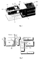
- FIG. 1 shows an exemplary construction of the device according to the invention.
- the storage containers BA, BB are connected for the corresponding process materials.
- the container BA, BB are fixed by not shown brackets at the interface S.
- the experimental chamber EK is attached in a connected to the interface S holding device H.
- the experimentation chamber EK has a threaded bore GB on the side facing the interface S.
- one of the threaded bore GB opposite to the threaded bore GB aligned threaded pin GS is attached.
- This set screw GB is expediently connected to a transmission / engine unit, not shown.
- a spring F is present.
- This spring F is attached on the one hand to the experimental chamber EK and on the other hand to the interface S. With the spring F, a bias voltage is generated, whereby, for example, when replacing the experimental chamber EK, the threaded bore GB can be reliably placed on the threaded pin GS. This makes it possible that without further intervention from the outside, a relative displacement of the experimental chamber EK can be achieved by operation of the threaded pin GS.
- FIG. 2 schematically shows a first exemplary embodiment of the device according to the invention in a first operating state 0.
- This illustration shows the start configuration of an experiment.
- An experiment chamber EK is inserted into the corresponding holder (not shown).
- the threaded bore (not shown) of the experimental chamber EK is fixed on the threaded pin GS of the interface S.
- To drive the threaded pin GS this is connected to a gear / motor unit M.
- the experimental chamber EK has a plurality of openings (not shown), which are closed with septa ST.
- the open ends of the needles K are in this configuration within the septa ST. This is essentially achieved in that the needles K are pressed into the septa ST by the spring F exerting a bias, or the experimental chamber EK is brought into this position by the motor-driven threaded pin GS.
- FIG. 2 shows by way of example two cannulas KK for two storage containers, wherein only one storage container BA is shown by way of example.
- the storage container BA has an opening (not shown), which is closed with a septum ST.
- the storage container BA is in such a way in the holder (not shown) of the interface S introduced that the cannula KK completely penetrates the septum ST, whereby the open end of the cannula KK is located inside the container BA.
- FIG 3 shows the exemplary arrangement in a second operating state A.
- the experiment chamber EK was displaced relative to the cannulas K by driving the threaded pin GS.
- the experiment chamber EK was moved in the direction of the arrow. It can be seen that a first part of the needles KK (the two upper ones) have completely penetrated the septa ST.
- the middle cannula KK is connected via the pump assembly P to the reservoir BA.
- process material is transported from the container BA into the experimental chamber EK.
- the upper cannula KK is connected to a volume expansion tank DB.
- This volume compensation tank DB serves to compensate for the build-up in the experimentation chamber EK by the filling pressure when using an experimental chamber EK with a rigid wall.
- the pressure building up due to the filling of the experimental chamber EK can also be compensated for by providing a flexible wall for the experimental chamber EK.
- the volume compensation tank DB can thus be omitted.
- the experiment chamber EK was in the direction of the arrow shifted so that in addition to the two upper cannulas KK also the lower Cannula KK completely penetrates the septa ST.
- the lower cannula KK is over a pump arrangement P with a storage container BB for a process material connected. By activating the corresponding pump can process material be led from the storage container BB in the experimental chamber EK.
- the experimental chamber EK is moved by means of appropriate rotation of the threaded pin GS opposite to the arrow direction shown.
- the experiment chamber EK is brought to the operating state 0 (see FIG. 2) after the end of an experiment.
- the experimental chamber EK and the storage containers BA, BB can be replaced.
- An advantage here is that due to the septa ST no outflow of process material from the experimental chamber EK or from the storage containers BA, BB and no intrusion of external contamination is possible.
- the appropriately designed as a roller pump pumps in the pump assembly P have the advantage that they can be used as a shut-off valve in the off state, ie the pump does not work. This means that even with a pressure difference between the inlet and outlet side of the pump no process material can flow through the pump.
- no process material from the needles KK emerge.
- FIG. 5 the individual operating states of Figs. 2-4 are shown in detail.
- the upper diagram shows the operating state 0.
- This operating state is the starting state at the beginning of an experiment or after the end of the experiment the state in which the arrangement is brought to exchange the experimental chamber EK or the storage containers (not shown).
- the illustration shows a retaining device H attached to the interface (not shown). Attached to this retaining device H are the cannulas KK, which are encased with sleeves HL.
- a gear / motor unit M is attached to the holding device H, which is connected to a threaded pin GS.
- the holding device H is arranged opposite the experimental chamber EK, which is oriented in such a way that a threaded bore GB executed in the experimental chamber EK is aligned with the threaded pin GS.
- four openings OG are exemplified in the experimentation chamber EK.
- the openings OG are closed with septa ST.
- the left opening OG is closed with a long septum ST and the second opening OG from the left and the second opening OG from the right with a short septum ST.
- the open ends of the cannulas KK each terminate within the septa ST, ie in this operating state no process material can be conducted from the cannulas KK into the experimental chamber EK.
- a sealing body DK is introduced in the right opening OG.
- the sealing body DK has a channel VK, which extends from the lying in the opening OG end face to a side surface.
- the sealing body DK is introduced into the opening OG in such a way that a ventilation of the experimental chamber EK is possible through the channel VK.
- a membrane ME can be arranged between the interior of the experimental chamber EK and the sealing body DK.
- the middle illustration shows the operating state A, in which the experimental chamber has been displaced in the direction of the arrow by corresponding rotation of the threaded pin GS.
- a displacement of the holding device H with respect to a fixed experimental chamber EK is possible.
- the middle and the right septum ST have been completely penetrated by the needles KK, so that the open ends of the cannulas KK terminate in the experimentation chamber EK, whereby it is possible to introduce process material.
- the lower diagram shows the operating state B.
- All septa ST are completely permeated by the respective cannulas KK.
- the Illustration also shows a arranged on the holder H stage VS.
- This level VS is arranged in alignment with the sealing body DK.
- the To replace stage VS by a controllable thread, so that regardless of the Relative position of the experimental chamber EK to the holding device H of the seal body DK for ventilation in the opening OG can be moved.
- the reference HL denotes the covers of the cannulas KK. These Covers serve to release the cannula KK when entering the septa ST and when removing the needles KK from septa ST to close.
- FIG. 6 shows an exemplary second embodiment of the invention.
- a second experimental chamber EK2 is present.
- This second experimental chamber EK2 is connected via its own holding device H to the pumping arrangement P common to the first experimental chamber EK1 and above to the common containers BA, BB.
- two needles KK are provided for each container BA, BB.
- a cannula KK supplies exclusively one experimental chamber EK, the other cannula KK exclusively supplies the other experimental chamber EK2.
- any number of experimentation chambers EK1, EK2 can be provided.
- FIG. 1 A third exemplary embodiment is shown in FIG.
- the output side AS of the pump P which is assigned to the container BB, connected to the input side ES of the container BA associated pump P.
- the process material can be pumped from container BB, for example, into the cannula KK of the container BA and from there into the experimental chamber EK.
- the output sides AS of two different containers BA, BC associated pumps P may be interconnected and fed to a common cannula KK.
- a further cannula KKS can be attached to the holding device H of the interface S.
- a sample can be drawn from the experimental chamber EK with a corresponding relative position of the experimental chamber EK to the holding device H via a connected pump P. This sample is pumped into a, according to the container BA, BB, BC connected sample vessel PS.
Landscapes
- Chemical & Material Sciences (AREA)
- Health & Medical Sciences (AREA)
- General Health & Medical Sciences (AREA)
- Chemical Kinetics & Catalysis (AREA)
- Analytical Chemistry (AREA)
- Clinical Laboratory Science (AREA)
- Dispersion Chemistry (AREA)
- Life Sciences & Earth Sciences (AREA)
- Immunology (AREA)
- Pathology (AREA)
- Physics & Mathematics (AREA)
- Hematology (AREA)
- Biochemistry (AREA)
- General Physics & Mathematics (AREA)
- Sampling And Sample Adjustment (AREA)
- Investigating Or Analysing Biological Materials (AREA)
- Confectionery (AREA)
- Transition And Organic Metals Composition Catalysts For Addition Polymerization (AREA)
- Devices For Use In Laboratory Experiments (AREA)
- Infusion, Injection, And Reservoir Apparatuses (AREA)
Abstract
Description
Es ist aber auch möglich, mittels druckbeaufschlagter Bevorratungsbehälter ein Strömen der Prozessstoffe aus den Behältern in die Experimentierkammer zu erreichen. Selbstverständlich ist es auch möglich, in der Experimentierkammer einen Unterdruck zu erzeugen, wodurch Prozessstoff aus den Behältern in die Experimentierkammer gesogen wird.
- Fig. 1
- einen beispielhaften Aufbau der erfindungsgemäßen Vorrichtung,
- Fig. 2
- in schematischer Darstellung eine erste beispielhafte Ausführungsform der erfindungsgemäßen Vorrichtung in einem ersten Betriebszustand 0,
- Fig. 3
- in schematischer Darstellung die Ausführungsform gemäß Fig. 2 in einem zweiten Betriebszustand A,
- Fig. 4
- in schematischer Darstellung die Ausführungsform gemäß Fig. 2 und 3 in einem dritten Betriebszustand B,
- Fig. 5
- eine Detailansicht der Betriebszustände 0, A, B aus Fig. 2-4,
- Fig. 6
- in schematischer Darstellung eine zweite beispielhafte Ausführungsform der erfindungsgemäßen Vorrichtung,
- Fig. 7
- in schematischer Darstellung eine dritte beispielhafte Ausführungsform der erfindungsgemäßen Vorrichtung.
Zur Herstellung einer Vorspannung zwischen der Experimentierkammer EK und der Schnittstelle S ist eine Feder F vorhanden. Diese Feder F ist einerseits an der Experimentierkammer EK und andererseits an der Schnittstelle S befestigt. Mit der Feder F wird eine Vorspannung erzeugt, wodurch z.B. beim Austausch der Experimentierkammer EK die Gewindebohrung GB zuverlässig auf den Gewindestift GS aufgesetzt werden kann. Dadurch ist es möglich, dass ohne weiteres Eingreifen von außen eine relative Verschiebung der Experimentierkammer EK durch Betrieb des Gewindestifts GS erreicht werden kann.
Die Experimentierkammer EK weist mehrere Öffnungen (nicht dargestellt) auf, welche mit Septen ST verschlossen sind. Die offenen Enden der Kanülen K befinden sich in dieser Konfiguration innerhalb der Septen ST. Dies wird im Wesentlichen dadurch erreicht, dass durch die eine Vorspannung ausübende Feder F die Kanülen K in die Septen ST hinein gedrückt werden oder die Experimentierkammer EK durch den motorangetriebenen Gewindestift GS in diese Position gebracht wird.
Der Bevorratungsbehälter BA weist eine Öffnung (nicht dargestellt) auf, welche mit einem Septum ST verschlossen ist. Der Bevorratungsbehälter BA ist dabei derart in die Halterung (nicht dargestellt) der Schnittstelle S eingebracht, dass die Kanüle KK das Septum ST vollständig durchdringt, wodurch sich das offene Ende der Kanüle KK im Innern des Behälters BA befindet.
Die obere Kanüle KK ist mit einem Volumenausgleichsbehälter DB verbunden. Dieser Volumenausgleichsbehälter DB dient dazu, bei Verwendung einer Experimentierkammer EK mit starrer Wandung den sich in der Experimentierkammer EK durch das Befüllen aufbauenden Druck zu kompensieren. Selbstverständlich kann der sich durch das Befüllen der Experimentierkammer EK aufbauende Druck auch dadurch kompensiert werden, dass für die Experimentierkammer EK eine flexible Wandung vorgesehen wird. Der Volumenausgleichsbehälter DB kann somit entfallen.
Die zweckmäßig als Rollerpumpen ausgebildeten Pumpen in der Pumpenanordnung P haben den Vorteil, dass sie im ausgeschalteten Zustand, d.h. die Pumpe arbeitet nicht, als Abschlußventil benutzt werden können. Das bedeutet, dass auch bei einer Druckdifferenz zwischen Ein- und Ausgangsseite der Pumpe kein Prozessstoff durch die Pumpe strömen kann. Somit kann beim Austausch der Bevorratungsbehälter BA, BB oder Experimentierkammer EK kein Prozessstoff aus den Kanülen KK austreten.
Die Darstellung zeigt eine an der Schnittstelle (nicht dargestellt) angebrachte Haltevorrichtung H. An dieser Haltevorrichtung H sind lösbar die Kanülen KK angebracht, welche mit Hülsen HL ummantelt sind. Außerdem ist an der Haltevorrichtung H ein Getriebe-/Motoreinheit M angebracht, welche mit einem Gewindestift GS verbunden ist.
Der Haltevorrichtung H gegenüber ist die Experimentierkammer EK angeordnet, welche derart ausgerichtet ist, dass eine in der Experimentierkammer EK ausgeführte Gewindebohrung GB dem Gewindestift GS fluchtend gegenüberliegt. Außerdem sind in der Experimentierkammer EK beispielhaft vier Öffnungen OG ausgeführt. Die Öffnungen OG sind mit Septen ST verschlossen. Beispielhaft ist die linke Öffnung OG mit einem lange Septum ST und die zweite Öffnung OG von links und die zweite Öffnung OG von rechts mit einem kurzen Septum ST verschlossen. Die offenen Enden der Kanülen KK enden jeweils innerhalb der Septen ST, d.h. in diesem Betriebszustand kann kein Prozessstoff aus den Kanülen KK in die Experimentierkammer EK geleitet werden.
In die rechte Öffnung OG ist ein Dichtungskörper DK eingebracht. Der Dichtungskörper DK weist einen Kanal VK auf, welcher von der in der Öffnung OG liegenden Stirnfläche zu einer Seitenfläche verläuft. Der Dichtungskörper DK ist dabei derart in die Öffnung OG eingebracht, dass durch den Kanal VK eine Belüftung der Experimentierkammer EK möglich ist. Zwischen dem Innenraum der Experimentierkammer EK und dem Dichtungskörper DK kann eine Membran ME angeordnet sein.
In dieser Darstellung sind das mittlere und das rechte Septum ST von den Kanülen KK vollständig durchdrungen worden, so dass die offenen Enden der Kanülen KK in der Experimentierkammer EK enden, wodurch ein Einleiten von Prozessstoff möglich ist.
Mit dieser Ausführungsform ist es somit möglich gleichzeitig gleiche, oder auch verschiedene Experimente durchzuführen. Selbstverständlich können beliebig viele Experimentierkammern EK1, EK2 vorgesehen werden.
Andererseits können die Ausgangsseiten AS zweier verschiedenen Behältern BA, BC zugeordneten Pumpen P miteinander verbunden sein und einer gemeinsamen Kanüle KK zugeführt sein.
Des Weiteren kann eine weitere Kanüle KKS an die Haltevorrichtung H der Schnittstelle S angebracht sein. Mittels dieser Kanüle KKS kann bei entsprechender relativer Position der Experimentierkammer EK zu der Haltevorrichtung H über eine angeschlossene Pumpe P eine Probe aus der Experimentierkammer EK gezogen werden. Diese Probe wird in ein, entsprechend der Behälter BA, BB, BC angeschlossenes Probengefäß PS gepumpt.
Claims (19)
- Vorrichtung zur Durchführung von Experimenten an Prozessstoffen umfassend ein oder mehrere Behälter (BA, BB, BC) zur Bevorratung von Prozessstoffen und eine oder mehrere Experimentierkammern (EK1, EK2) zur Aufnahme der Prozessstoffe, dadurch gekennzeichnet, dass den ein oder mehreren Öffnungen (OG) der Experimentierkammer (EK1, EK2) jeweils ein zur Aufnahme vorgesehenes Septum (ST) zugeordnet ist, dass jeweils eine zur Durchdringung des Septums (ST) vorgesehene Kanüle (KK) vorhanden ist und dass Mittel (M, GB, GS) vorhanden sind zur relativen Verschiebung der Experimentierkammer (EK1, EK2) und der Kanülen (KK).
- Vorrichtung nach Anspruch 1, dadurch gekennzeichnet, dass eine Schnittstelle (S) vorhanden ist zur Herstellung einer Verbindung zwischen den Kanülen (KK) und den Bevorratungsbehältern (BA, BB, BC) sowie zwischen den Kanülen (KK) und der Experimentierkammer (EK1, EK2).
- Vorrichtung nach Anspruch 2, dadurch gekennzeichnet, dass weitere Kanülen (KK) zur Durchdringung eines einer Öffnung (OG) eines Bevorratungsbehälters (BA, BB, BC) zugeordneten Septums (ST) vorhanden sind.
- Vorrichtung nach Anspruch 2 oder 3, dadurch gekennzeichnet, dass die Verbindung zwischen der Schnittstelle (S) und den Kanülen (KK) als lösbare Schlauchverbindung ausgeführt ist.
- Vorrichtung nach Anspruch 2 oder 3, dadurch gekennzeichnet, dass die Kanülen (KK) an der Schnittstelle (S) befestigt sind.
- Vorrichtung nach Anspruch 5, dadurch gekennzeichnet, dass die Experimentierkammer (EK1, EK2) eine weitere Öffnung (OG) aufweist, welcher ein Dichtungskörper (DK) zugeordnet ist, welcher einen von der dem Innenraum der Experimentierkammer (EK1, EK2) zugewandten Stirnfläche des Dichtungskörpers (DK) zu einer Seitenfläche des Dichtungskörpers (DK) verlaufenden Kanal (VK) aufweist.
- Vorrichtung nach Anspruch 6, dadurch gekennzeichnet, dass die Schnittstelle (S) dem Dichtungskörper (DK) gegenüberliegende Mittel (VS) zur Verschiebung des Dichtungskörpers (DK) aufweist.
- Vorrichtung nach einem der Ansprüche 5-7, dadurch gekennzeichnet, dass das Mittel (M, GB, GS) zur relativen Verschiebung der Septen (ST) bezüglich der Kanüle (KK) eine in der Experimentierkammer (EK1, EK2) ausgeführte Gewindebohrung (GB) und ein, an der Schnittstelle (S) zur Aufnahme in die Gewindebohrung (GB) vorgesehenen Gewindestift (GS) umfasst.
- Vorrichtung nach Anspruch 8, dadurch gekennzeichnet, dass Mittel (M) zum Antrieb des Gewindestifts (GS) vorhanden sind.
- Vorrichtung nach einem der vorangehenden Ansprüche, dadurch gekennzeichnet, dass Mittel (F) zur Herstellung einer Vorspannung zwischen der Experimentierkammer (EK1, EK2) und den Kanülen (KK) vorhanden sind.
- Vorrichtung nach einem der vorangehenden Ansprüche, dadurch gekennzeichnet, dass die ein oder mehreren Septen (ST) jeweils eine vorgebbare Länge aufweisen.
- Vorrichtung nach Anspruch 11, dadurch gekennzeichnet, dass die Kanülen (KK) derart angeordnet sind, dass sich bei einer ersten vorgebbaren Position 0 das offene Ende aller Kanülen (KK) im Inneren der jeweiligen Septen (ST) befindet, dass bei einer zweiten vorgebbaren Position A für einen ersten Teil der Kanülen (KK) sich das offene Ende der Kanüle (KK) im Inneren der jeweiligen Septen (ST) befindet und für einen zweiten Teil der Kanülen (KK) die jeweiligen Septen (ST) von den offenen Enden der Kanülen (KK) vollständig durchdrungen sind und dass bei einer dritten vorgebbaren Position B alle Septen (ST) von den offenen Enden der Kanülen (KK) vollständig durchdrungen sind.
- Vorrichtung nach einem der Ansprüche 2-12, dadurch gekennzeichnet, dass die Schnittstelle (S) einem Behälter (BA, BB, BC) zugeordnete Mittel (P) mit einer Ein- und Ausgangsseite (ES, AS) zum Pumpen des Prozessstoffes aus dem Behälter (BA, BB, BC) in die Experimentierkammer (EK1, EK2) umfasst.
- Vorrichtung nach Anspruch 13, dadurch gekennzeichnet, dass die Ausgangsseite (AS) eines Mittels (P) mit mindestens einer Kanüle (KK) verbunden ist.
- Vorrichtung nach Anspruch 13, dadurch gekennzeichnet, dass die Ausgangsseiten (AS) zweier Pumpmittel (P) mit einer gemeinsamen Kanüle (KK) verbunden sind.
- Vorrichtung nach Anspruch 13 oder 15, dadurch gekennzeichnet, dass die Ausgangsseite (AS) eines ersten Pumpmittels (P) mit der Eingangsseite (ES) eines zweiten Pumpmittels (P) verbunden ist.
- Vorrichtung nach einem der vorangehenden Ansprüche, dadurch gekennzeichnet, dass Mittel (E) zur Entlüftung der Experimentierkammer (EK1, EK2) vorhanden sind.
- Vorrichtung nach einem der vorangehenden Ansprüche, dadurch gekennzeichnet, dass Abdeckungen (HL) für die Kanülen (K, KK) vorhanden sind.
- Verfahren zur Durchführung von Experimenten an Prozessstoffen umfassend ein oder mehrere Behälter (BA, BB, BC) zur Bevorratung von Prozessstoffen und eine Experimentierkammer (EK1, EK2) zur Aufnahme der Prozessstoffe, dadurch gekennzeichnet, dass eine mit ein oder mehreren Öffnungen (OG) ausgeführte Experimentierkammer (EK1, EK2), denen Öffnungen (OG) jeweils ein zur Aufnahme vorgesehenes Septum (ST) und zur Durchdringung der Septen (ST) vorgesehene Kanülen (KK) zugeordnet sind relativ zu den Kanülen (KK) verschoben wird.
Applications Claiming Priority (2)
| Application Number | Priority Date | Filing Date | Title |
|---|---|---|---|
| DE10349513 | 2003-10-23 | ||
| DE10349513A DE10349513B4 (de) | 2003-10-23 | 2003-10-23 | Experimentiervorrichtung |
Publications (3)
| Publication Number | Publication Date |
|---|---|
| EP1525918A2 true EP1525918A2 (de) | 2005-04-27 |
| EP1525918A3 EP1525918A3 (de) | 2005-06-22 |
| EP1525918B1 EP1525918B1 (de) | 2011-04-13 |
Family
ID=34384439
Family Applications (1)
| Application Number | Title | Priority Date | Filing Date |
|---|---|---|---|
| EP04022137A Expired - Lifetime EP1525918B1 (de) | 2003-10-23 | 2004-09-17 | Experimentiervorrichtung |
Country Status (4)
| Country | Link |
|---|---|
| EP (1) | EP1525918B1 (de) |
| AT (1) | ATE505268T1 (de) |
| DE (2) | DE10349513B4 (de) |
| ES (1) | ES2363338T3 (de) |
Cited By (9)
| Publication number | Priority date | Publication date | Assignee | Title |
|---|---|---|---|---|
| EP2869924A1 (de) * | 2012-07-03 | 2015-05-13 | Merck Patent GmbH | Vorrichtung zur probenvorbereitung |
| WO2015062714A3 (en) * | 2013-10-28 | 2015-07-02 | Biocartis Nv | Transfer device of biological material |
| EP2905623A1 (de) * | 2014-02-07 | 2015-08-12 | Grifols Worldwide Operations Limited | Vorrichtung zur Entnahme von Proben aus Behältern |
| WO2015197176A1 (de) * | 2014-06-27 | 2015-12-30 | Euroimmun Medizinische Labordiagnostika Ag | Verfahren und vorrichtung zur überführung von flüssigkeiten |
| WO2019090370A1 (de) * | 2017-11-10 | 2019-05-16 | Erba Technologies Austria Gmbh | Sensorkassette |
| EP2864503B1 (de) * | 2012-06-26 | 2019-10-09 | Axxin Pty Ltd | Nukleinsäureamplifikations- und -nachweiskit |
| EP2300832B1 (de) * | 2008-07-14 | 2020-01-08 | Koninklijke Philips N.V. | Vorrichtung zur verwendung in molekularen diagnosetests |
| US11559464B2 (en) | 2016-05-16 | 2023-01-24 | Haemonetics Corporation | Sealer-less plasma bottle and top for same |
| US11648179B2 (en) | 2016-05-16 | 2023-05-16 | Haemonetics Corporation | Sealer-less plasma bottle and top for same |
Citations (2)
| Publication number | Priority date | Publication date | Assignee | Title |
|---|---|---|---|---|
| DE10149684A1 (de) | 2001-10-09 | 2003-04-24 | Clondiag Chip Tech Gmbh | Vorrichtung zur Halterung eines Substanzbibliothekenträgers |
| DE10307227A1 (de) | 2003-02-14 | 2004-08-26 | Cytocentrics Ccs Gmbh | Verfahren und Vorrichtung zum Kontaktieren einer Mikrofluidstruktur |
Family Cites Families (6)
| Publication number | Priority date | Publication date | Assignee | Title |
|---|---|---|---|---|
| FR2308932A1 (fr) * | 1975-04-24 | 1976-11-19 | Aquitaine Petrole | Dispositif d'introduction d'echantillons dans un chromatographe |
| DE3817101C2 (de) * | 1988-05-19 | 1998-05-20 | Axel Von Brand | Vorrichtung zum Überleiten von Flüssigkeit von einem Behältnis zu einem anderen Behältnis |
| DE69219612T2 (de) * | 1991-11-01 | 1997-10-02 | Univ Birmingham | Prüfungsvorrichtung |
| US5888826A (en) * | 1994-06-30 | 1999-03-30 | Dade Behring Inc. | Combination reagent holding and test device |
| DE29506669U1 (de) * | 1995-04-12 | 1995-06-29 | Schulz, Hans-Joachim, Dr., 10249 Berlin | Laborgerät zur gleichzeitigen, manuellen Durchführung mehrerer chemischer Reaktionen nach einem Stecksystem |
| EP1214149A2 (de) * | 1999-09-21 | 2002-06-19 | Genome Therapeutics Corp. | Vorrichtung zur schnellen bearbeitung von dns-proben mit vollintegrierter flüssigkeitsprobenhandhabung, thermischen zyklen und reinigung |
-
2003
- 2003-10-23 DE DE10349513A patent/DE10349513B4/de not_active Expired - Fee Related
-
2004
- 2004-09-17 AT AT04022137T patent/ATE505268T1/de active
- 2004-09-17 EP EP04022137A patent/EP1525918B1/de not_active Expired - Lifetime
- 2004-09-17 ES ES04022137T patent/ES2363338T3/es not_active Expired - Lifetime
- 2004-09-17 DE DE502004012393T patent/DE502004012393D1/de not_active Expired - Lifetime
Patent Citations (2)
| Publication number | Priority date | Publication date | Assignee | Title |
|---|---|---|---|---|
| DE10149684A1 (de) | 2001-10-09 | 2003-04-24 | Clondiag Chip Tech Gmbh | Vorrichtung zur Halterung eines Substanzbibliothekenträgers |
| DE10307227A1 (de) | 2003-02-14 | 2004-08-26 | Cytocentrics Ccs Gmbh | Verfahren und Vorrichtung zum Kontaktieren einer Mikrofluidstruktur |
Cited By (20)
| Publication number | Priority date | Publication date | Assignee | Title |
|---|---|---|---|---|
| EP2300832B1 (de) * | 2008-07-14 | 2020-01-08 | Koninklijke Philips N.V. | Vorrichtung zur verwendung in molekularen diagnosetests |
| EP2864503B1 (de) * | 2012-06-26 | 2019-10-09 | Axxin Pty Ltd | Nukleinsäureamplifikations- und -nachweiskit |
| EP2869924A1 (de) * | 2012-07-03 | 2015-05-13 | Merck Patent GmbH | Vorrichtung zur probenvorbereitung |
| US10279343B2 (en) | 2013-10-28 | 2019-05-07 | Biocartis Nv | Transfer device of biological material |
| WO2015062714A3 (en) * | 2013-10-28 | 2015-07-02 | Biocartis Nv | Transfer device of biological material |
| JP2017500010A (ja) * | 2013-10-28 | 2017-01-05 | ビオカルティ ナームローゼ フェノーツハップBiocartis NV | 生体材料の搬送装置 |
| EP2905623A1 (de) * | 2014-02-07 | 2015-08-12 | Grifols Worldwide Operations Limited | Vorrichtung zur Entnahme von Proben aus Behältern |
| US9572749B2 (en) | 2014-02-07 | 2017-02-21 | Grifols Worldwide Operations Limited | Device for taking samples from containers |
| EP2959971A1 (de) * | 2014-06-27 | 2015-12-30 | Euroimmun Medizinische Labordiagnostika AG | Verfahren und Vorrichtung zur Überführung von Flüssigkeiten |
| CN106824312A (zh) * | 2014-06-27 | 2017-06-13 | 欧蒙医学诊断技术有限公司 | 用于转移液体的方法和装置 |
| CN106457248A (zh) * | 2014-06-27 | 2017-02-22 | 欧蒙医学诊断技术有限公司 | 用于转移液体的方法和装置 |
| US10345206B2 (en) | 2014-06-27 | 2019-07-09 | Euroimmun Medizinische Labordiagnostika Ag | Method and device for transferring liquids |
| WO2015197176A1 (de) * | 2014-06-27 | 2015-12-30 | Euroimmun Medizinische Labordiagnostika Ag | Verfahren und vorrichtung zur überführung von flüssigkeiten |
| CN106457248B (zh) * | 2014-06-27 | 2020-02-21 | 欧蒙医学实验诊断股份公司 | 用于转移液体的装置、方法和用途 |
| US11559464B2 (en) | 2016-05-16 | 2023-01-24 | Haemonetics Corporation | Sealer-less plasma bottle and top for same |
| US11648179B2 (en) | 2016-05-16 | 2023-05-16 | Haemonetics Corporation | Sealer-less plasma bottle and top for same |
| WO2019090370A1 (de) * | 2017-11-10 | 2019-05-16 | Erba Technologies Austria Gmbh | Sensorkassette |
| CN111344062B (zh) * | 2017-11-10 | 2022-12-06 | 尔巴科技奥地利有限公司 | 传感器盒 |
| US11376586B2 (en) | 2017-11-10 | 2022-07-05 | Erba Technologies Austria Gmbh | Sensor cassette |
| CN111344062A (zh) * | 2017-11-10 | 2020-06-26 | 尔巴科技奥地利有限公司 | 传感器盒 |
Also Published As
| Publication number | Publication date |
|---|---|
| DE10349513A1 (de) | 2005-06-02 |
| DE502004012393D1 (de) | 2011-05-26 |
| EP1525918A3 (de) | 2005-06-22 |
| EP1525918B1 (de) | 2011-04-13 |
| ATE505268T1 (de) | 2011-04-15 |
| DE10349513B4 (de) | 2006-08-31 |
| ES2363338T3 (es) | 2011-08-01 |
Similar Documents
| Publication | Publication Date | Title |
|---|---|---|
| EP3159021B1 (de) | Vorrichtung zur transplantation von körperfett | |
| DE69104367T2 (de) | Ausgabeverfahren und -vorrichtung, insbesondere für dichtungs-/klebemittel. | |
| EP1525918B1 (de) | Experimentiervorrichtung | |
| EP3998121B1 (de) | Vorrichtung zur oberflächenbehandlung von formteilen | |
| EP4089161A1 (de) | Substrat zur untersuchung von proben und system umfassend das substrat | |
| DE19906409B4 (de) | Dosiervorrichtung sowie Verfahren zum Betreiben einer Dosiervorrichtung | |
| DE3828004C2 (de) | ||
| EP4357657A1 (de) | Ventileinrichtung, baumaschine und verfahren | |
| EP2163892B1 (de) | Abwasser-Prozess-Analysegerät | |
| DE102016200960B4 (de) | Pumpvorrichtung | |
| DE4335514C2 (de) | Vorrichtung zum Austauschen von Fluids | |
| EP1397483B1 (de) | Mikrofluidsystem | |
| EP1556647A1 (de) | Verfahren und vorrichtung zur entnahme von flüssigen proben aus druckbehältern | |
| DE2613662C2 (de) | Vorrichtung zur chemisch-mechanischen Reinigung der Getränkeförderleitungen einer Getränkeschankanlage | |
| EP2024726B1 (de) | Kolbenspritze zur entnahme von proben in einer leitung geführten gasförmigen oder flüssigen mediums | |
| DE2659690A1 (de) | Mehrstufige dialyse-apparatur | |
| DE8600311U1 (de) | Vorrichtung zur Beseitigung von Luftblasen aus Flüssigkeiten | |
| EP0258490B1 (de) | Vorrichtung zur Durchführung zellbiologischer Versuche | |
| DE102024103900A1 (de) | Kombinierte spritzen-kolben-vorrichtung und verwendung | |
| WO2025067818A1 (de) | Vorrichtung zur fluidkontaktierung fluidischer systeme | |
| DE3036097A1 (de) | Foerderpumpe fuer brunnen | |
| DE102007018413A1 (de) | Vorrichtung und Verfahren zur Wiederbefüllung von Tintenpatronen | |
| WO2006045619A1 (de) | Vorrichtung und verfahren zur parallelen aufbereitung von biopolymeren | |
| DE10102138A1 (de) | Dosiereinrichtung und Verfahren zum Dosieren für reines Wasser | |
| DE20115643U1 (de) | Vorrichtung zum Dosieren von Flüssigkeiten |
Legal Events
| Date | Code | Title | Description |
|---|---|---|---|
| PUAI | Public reference made under article 153(3) epc to a published international application that has entered the european phase |
Free format text: ORIGINAL CODE: 0009012 |
|
| AK | Designated contracting states |
Kind code of ref document: A2 Designated state(s): AT BE BG CH CY CZ DE DK EE ES FI FR GB GR HU IE IT LI LU MC NL PL PT RO SE SI SK TR |
|
| AX | Request for extension of the european patent |
Extension state: AL HR LT LV MK |
|
| PUAL | Search report despatched |
Free format text: ORIGINAL CODE: 0009013 |
|
| AK | Designated contracting states |
Kind code of ref document: A3 Designated state(s): AT BE BG CH CY CZ DE DK EE ES FI FR GB GR HU IE IT LI LU MC NL PL PT RO SE SI SK TR |
|
| AX | Request for extension of the european patent |
Extension state: AL HR LT LV MK |
|
| 17P | Request for examination filed |
Effective date: 20050818 |
|
| AKX | Designation fees paid |
Designated state(s): AT BE BG CH CY CZ DE DK EE ES FI FR GB GR HU IE IT LI LU MC NL PL PT RO SE SI SK TR |
|
| RAP1 | Party data changed (applicant data changed or rights of an application transferred) |
Owner name: EADS ASTRIUM GMBH |
|
| GRAP | Despatch of communication of intention to grant a patent |
Free format text: ORIGINAL CODE: EPIDOSNIGR1 |
|
| GRAS | Grant fee paid |
Free format text: ORIGINAL CODE: EPIDOSNIGR3 |
|
| GRAA | (expected) grant |
Free format text: ORIGINAL CODE: 0009210 |
|
| AK | Designated contracting states |
Kind code of ref document: B1 Designated state(s): AT BE BG CH CY CZ DE DK EE ES FI FR GB GR HU IE IT LI LU MC NL PL PT RO SE SI SK TR |
|
| REG | Reference to a national code |
Ref country code: GB Ref legal event code: FG4D Free format text: NOT ENGLISH |
|
| REG | Reference to a national code |
Ref country code: CH Ref legal event code: EP |
|
| REG | Reference to a national code |
Ref country code: DE Ref legal event code: R081 Ref document number: 502004012393 Country of ref document: DE Owner name: AIRBUS DEFENCE AND SPACE GMBH, DE Free format text: FORMER OWNER: EADS SPACE TRANSPORTATION GMBH, 28199 BREMEN, DE Ref country code: DE Ref legal event code: R081 Ref document number: 502004012393 Country of ref document: DE Owner name: AIRBUS DS GMBH, DE Free format text: FORMER OWNER: EADS SPACE TRANSPORTATION GMBH, 28199 BREMEN, DE |
|
| REG | Reference to a national code |
Ref country code: IE Ref legal event code: FG4D Free format text: LANGUAGE OF EP DOCUMENT: GERMAN |
|
| REF | Corresponds to: |
Ref document number: 502004012393 Country of ref document: DE Date of ref document: 20110526 Kind code of ref document: P |
|
| REG | Reference to a national code |
Ref country code: DE Ref legal event code: R096 Ref document number: 502004012393 Country of ref document: DE Effective date: 20110526 |
|
| REG | Reference to a national code |
Ref country code: NL Ref legal event code: T3 |
|
| REG | Reference to a national code |
Ref country code: ES Ref legal event code: FG2A Ref document number: 2363338 Country of ref document: ES Kind code of ref document: T3 Effective date: 20110801 |
|
| PG25 | Lapsed in a contracting state [announced via postgrant information from national office to epo] |
Ref country code: PT Free format text: LAPSE BECAUSE OF FAILURE TO SUBMIT A TRANSLATION OF THE DESCRIPTION OR TO PAY THE FEE WITHIN THE PRESCRIBED TIME-LIMIT Effective date: 20110816 Ref country code: SE Free format text: LAPSE BECAUSE OF FAILURE TO SUBMIT A TRANSLATION OF THE DESCRIPTION OR TO PAY THE FEE WITHIN THE PRESCRIBED TIME-LIMIT Effective date: 20110413 |
|
| REG | Reference to a national code |
Ref country code: IE Ref legal event code: FD4D |
|
| PG25 | Lapsed in a contracting state [announced via postgrant information from national office to epo] |
Ref country code: GR Free format text: LAPSE BECAUSE OF FAILURE TO SUBMIT A TRANSLATION OF THE DESCRIPTION OR TO PAY THE FEE WITHIN THE PRESCRIBED TIME-LIMIT Effective date: 20110714 Ref country code: SI Free format text: LAPSE BECAUSE OF FAILURE TO SUBMIT A TRANSLATION OF THE DESCRIPTION OR TO PAY THE FEE WITHIN THE PRESCRIBED TIME-LIMIT Effective date: 20110413 Ref country code: FI Free format text: LAPSE BECAUSE OF FAILURE TO SUBMIT A TRANSLATION OF THE DESCRIPTION OR TO PAY THE FEE WITHIN THE PRESCRIBED TIME-LIMIT Effective date: 20110413 Ref country code: CY Free format text: LAPSE BECAUSE OF FAILURE TO SUBMIT A TRANSLATION OF THE DESCRIPTION OR TO PAY THE FEE WITHIN THE PRESCRIBED TIME-LIMIT Effective date: 20110413 |
|
| PG25 | Lapsed in a contracting state [announced via postgrant information from national office to epo] |
Ref country code: IE Free format text: LAPSE BECAUSE OF FAILURE TO SUBMIT A TRANSLATION OF THE DESCRIPTION OR TO PAY THE FEE WITHIN THE PRESCRIBED TIME-LIMIT Effective date: 20110413 Ref country code: EE Free format text: LAPSE BECAUSE OF FAILURE TO SUBMIT A TRANSLATION OF THE DESCRIPTION OR TO PAY THE FEE WITHIN THE PRESCRIBED TIME-LIMIT Effective date: 20110413 Ref country code: CZ Free format text: LAPSE BECAUSE OF FAILURE TO SUBMIT A TRANSLATION OF THE DESCRIPTION OR TO PAY THE FEE WITHIN THE PRESCRIBED TIME-LIMIT Effective date: 20110413 |
|
| PLBE | No opposition filed within time limit |
Free format text: ORIGINAL CODE: 0009261 |
|
| STAA | Information on the status of an ep patent application or granted ep patent |
Free format text: STATUS: NO OPPOSITION FILED WITHIN TIME LIMIT |
|
| PG25 | Lapsed in a contracting state [announced via postgrant information from national office to epo] |
Ref country code: PL Free format text: LAPSE BECAUSE OF FAILURE TO SUBMIT A TRANSLATION OF THE DESCRIPTION OR TO PAY THE FEE WITHIN THE PRESCRIBED TIME-LIMIT Effective date: 20110413 Ref country code: RO Free format text: LAPSE BECAUSE OF FAILURE TO SUBMIT A TRANSLATION OF THE DESCRIPTION OR TO PAY THE FEE WITHIN THE PRESCRIBED TIME-LIMIT Effective date: 20110413 Ref country code: DK Free format text: LAPSE BECAUSE OF FAILURE TO SUBMIT A TRANSLATION OF THE DESCRIPTION OR TO PAY THE FEE WITHIN THE PRESCRIBED TIME-LIMIT Effective date: 20110413 Ref country code: SK Free format text: LAPSE BECAUSE OF FAILURE TO SUBMIT A TRANSLATION OF THE DESCRIPTION OR TO PAY THE FEE WITHIN THE PRESCRIBED TIME-LIMIT Effective date: 20110413 |
|
| 26N | No opposition filed |
Effective date: 20120116 |
|
| PG25 | Lapsed in a contracting state [announced via postgrant information from national office to epo] |
Ref country code: MC Free format text: LAPSE BECAUSE OF NON-PAYMENT OF DUE FEES Effective date: 20110930 |
|
| REG | Reference to a national code |
Ref country code: DE Ref legal event code: R097 Ref document number: 502004012393 Country of ref document: DE Effective date: 20120116 |
|
| GBPC | Gb: european patent ceased through non-payment of renewal fee |
Effective date: 20110917 |
|
| PG25 | Lapsed in a contracting state [announced via postgrant information from national office to epo] |
Ref country code: GB Free format text: LAPSE BECAUSE OF NON-PAYMENT OF DUE FEES Effective date: 20110917 |
|
| REG | Reference to a national code |
Ref country code: AT Ref legal event code: MM01 Ref document number: 505268 Country of ref document: AT Kind code of ref document: T Effective date: 20110917 |
|
| PG25 | Lapsed in a contracting state [announced via postgrant information from national office to epo] |
Ref country code: AT Free format text: LAPSE BECAUSE OF NON-PAYMENT OF DUE FEES Effective date: 20110917 |
|
| PG25 | Lapsed in a contracting state [announced via postgrant information from national office to epo] |
Ref country code: LU Free format text: LAPSE BECAUSE OF NON-PAYMENT OF DUE FEES Effective date: 20110917 |
|
| PG25 | Lapsed in a contracting state [announced via postgrant information from national office to epo] |
Ref country code: BG Free format text: LAPSE BECAUSE OF FAILURE TO SUBMIT A TRANSLATION OF THE DESCRIPTION OR TO PAY THE FEE WITHIN THE PRESCRIBED TIME-LIMIT Effective date: 20110713 |
|
| PG25 | Lapsed in a contracting state [announced via postgrant information from national office to epo] |
Ref country code: TR Free format text: LAPSE BECAUSE OF FAILURE TO SUBMIT A TRANSLATION OF THE DESCRIPTION OR TO PAY THE FEE WITHIN THE PRESCRIBED TIME-LIMIT Effective date: 20110413 |
|
| PG25 | Lapsed in a contracting state [announced via postgrant information from national office to epo] |
Ref country code: HU Free format text: LAPSE BECAUSE OF FAILURE TO SUBMIT A TRANSLATION OF THE DESCRIPTION OR TO PAY THE FEE WITHIN THE PRESCRIBED TIME-LIMIT Effective date: 20110413 |
|
| REG | Reference to a national code |
Ref country code: DE Ref legal event code: R081 Ref document number: 502004012393 Country of ref document: DE Owner name: AIRBUS DEFENCE AND SPACE GMBH, DE Free format text: FORMER OWNER: EADS ASTRIUM GMBH, 85521 OTTOBRUNN, DE Ref country code: DE Ref legal event code: R082 Ref document number: 502004012393 Country of ref document: DE Representative=s name: PATENT- UND RECHTSANWALTSKANZLEI DAUB, DE Ref country code: DE Ref legal event code: R081 Ref document number: 502004012393 Country of ref document: DE Owner name: AIRBUS DS GMBH, DE Free format text: FORMER OWNER: EADS ASTRIUM GMBH, 85521 OTTOBRUNN, DE |
|
| REG | Reference to a national code |
Ref country code: CH Ref legal event code: PFA Owner name: AIRBUS DS GMBH, DE Free format text: FORMER OWNER: EADS ASTRIUM GMBH, DE |
|
| REG | Reference to a national code |
Ref country code: FR Ref legal event code: PLFP Year of fee payment: 12 |
|
| REG | Reference to a national code |
Ref country code: FR Ref legal event code: CA Effective date: 20150916 Ref country code: FR Ref legal event code: CD Owner name: AIRBUS DS GMBH Effective date: 20150916 |
|
| REG | Reference to a national code |
Ref country code: FR Ref legal event code: PLFP Year of fee payment: 13 |
|
| REG | Reference to a national code |
Ref country code: CH Ref legal event code: NV Representative=s name: PATENTANWALTSKANZLEI DAUB, CH |
|
| REG | Reference to a national code |
Ref country code: DE Ref legal event code: R082 Ref document number: 502004012393 Country of ref document: DE Representative=s name: PATENT- UND RECHTSANWALTSKANZLEI DAUB, DE Ref country code: DE Ref legal event code: R081 Ref document number: 502004012393 Country of ref document: DE Owner name: AIRBUS DEFENCE AND SPACE GMBH, DE Free format text: FORMER OWNER: AIRBUS DS GMBH, 82024 TAUFKIRCHEN, DE |
|
| REG | Reference to a national code |
Ref country code: FR Ref legal event code: PLFP Year of fee payment: 14 |
|
| REG | Reference to a national code |
Ref country code: CH Ref legal event code: PFUS Owner name: AIRBUS DEFENCE AND SPACE GMBH, DE Free format text: FORMER OWNER: AIRBUS DS GMBH, DE |
|
| REG | Reference to a national code |
Ref country code: NL Ref legal event code: HC Owner name: AIRBUS DS GMBH; DE Free format text: DETAILS ASSIGNMENT: CHANGE OF OWNER(S), CHANGE OF OWNER(S) NAME; FORMER OWNER NAME: EADS ASTRIUM GMBH Effective date: 20180220 Ref country code: NL Ref legal event code: PD Owner name: AIRBUS DEFENCE AND SPACE GMBH; DE Free format text: DETAILS ASSIGNMENT: CHANGE OF OWNER(S), MERGE; FORMER OWNER NAME: AIRBUS DS GMBH Effective date: 20180220 |
|
| REG | Reference to a national code |
Ref country code: ES Ref legal event code: PC2A Owner name: AIRBUS DEFENCE AND SPACE GMBH Effective date: 20180528 Ref country code: ES Ref legal event code: PC2A Effective date: 20180528 |
|
| REG | Reference to a national code |
Ref country code: BE Ref legal event code: HC Owner name: AIRBUS DS GMBH; DE Free format text: DETAILS ASSIGNMENT: CHANGE OF OWNER(S), CHANGEMENT NOM PROPRIETAIRE; FORMER OWNER NAME: ASTRIUM GMBH Effective date: 20150616 Ref country code: BE Ref legal event code: PD Owner name: AIRBUS DEFENCE AND SPACE GMBH; DE Free format text: DETAILS ASSIGNMENT: CHANGE OF OWNER(S), FUSION; FORMER OWNER NAME: AIRBUS DS GMBH Effective date: 20180413 |
|
| REG | Reference to a national code |
Ref country code: FR Ref legal event code: PLFP Year of fee payment: 15 |
|
| REG | Reference to a national code |
Ref country code: CH Ref legal event code: PCAR Free format text: NEW ADDRESS: LEUTSCHENBACHSTRASSE 95, 8050 ZUERICH (CH) |
|
| PGFP | Annual fee paid to national office [announced via postgrant information from national office to epo] |
Ref country code: ES Payment date: 20191022 Year of fee payment: 16 |
|
| PGFP | Annual fee paid to national office [announced via postgrant information from national office to epo] |
Ref country code: DE Payment date: 20200925 Year of fee payment: 17 Ref country code: NL Payment date: 20200925 Year of fee payment: 17 Ref country code: FR Payment date: 20200914 Year of fee payment: 17 |
|
| PGFP | Annual fee paid to national office [announced via postgrant information from national office to epo] |
Ref country code: IT Payment date: 20200922 Year of fee payment: 17 Ref country code: CH Payment date: 20200921 Year of fee payment: 17 Ref country code: BE Payment date: 20200925 Year of fee payment: 17 |
|
| REG | Reference to a national code |
Ref country code: ES Ref legal event code: FD2A Effective date: 20220117 |
|
| REG | Reference to a national code |
Ref country code: DE Ref legal event code: R119 Ref document number: 502004012393 Country of ref document: DE |
|
| REG | Reference to a national code |
Ref country code: NL Ref legal event code: MM Effective date: 20211001 |
|
| REG | Reference to a national code |
Ref country code: CH Ref legal event code: PL |
|
| REG | Reference to a national code |
Ref country code: BE Ref legal event code: MM Effective date: 20210930 |
|
| PG25 | Lapsed in a contracting state [announced via postgrant information from national office to epo] |
Ref country code: ES Free format text: LAPSE BECAUSE OF NON-PAYMENT OF DUE FEES Effective date: 20200918 |
|
| PG25 | Lapsed in a contracting state [announced via postgrant information from national office to epo] |
Ref country code: NL Free format text: LAPSE BECAUSE OF NON-PAYMENT OF DUE FEES Effective date: 20211001 |
|
| PG25 | Lapsed in a contracting state [announced via postgrant information from national office to epo] |
Ref country code: FR Free format text: LAPSE BECAUSE OF NON-PAYMENT OF DUE FEES Effective date: 20210930 Ref country code: DE Free format text: LAPSE BECAUSE OF NON-PAYMENT OF DUE FEES Effective date: 20220401 Ref country code: BE Free format text: LAPSE BECAUSE OF NON-PAYMENT OF DUE FEES Effective date: 20210930 |
|
| PG25 | Lapsed in a contracting state [announced via postgrant information from national office to epo] |
Ref country code: LI Free format text: LAPSE BECAUSE OF NON-PAYMENT OF DUE FEES Effective date: 20210930 Ref country code: CH Free format text: LAPSE BECAUSE OF NON-PAYMENT OF DUE FEES Effective date: 20210930 |
|
| PG25 | Lapsed in a contracting state [announced via postgrant information from national office to epo] |
Ref country code: IT Free format text: LAPSE BECAUSE OF NON-PAYMENT OF DUE FEES Effective date: 20210917 |