EP1524692A2 - Flüssigkeitsdurchströmter Kühlmantel zum Kühlen einer elektronischen Vorrichtung - Google Patents
Flüssigkeitsdurchströmter Kühlmantel zum Kühlen einer elektronischen Vorrichtung Download PDFInfo
- Publication number
- EP1524692A2 EP1524692A2 EP04005471A EP04005471A EP1524692A2 EP 1524692 A2 EP1524692 A2 EP 1524692A2 EP 04005471 A EP04005471 A EP 04005471A EP 04005471 A EP04005471 A EP 04005471A EP 1524692 A2 EP1524692 A2 EP 1524692A2
- Authority
- EP
- European Patent Office
- Prior art keywords
- liquid cooling
- radiating fins
- post
- coolant
- cooling jacket
- Prior art date
- Legal status (The legal status is an assumption and is not a legal conclusion. Google has not performed a legal analysis and makes no representation as to the accuracy of the status listed.)
- Withdrawn
Links
Images


Classifications
-
- H—ELECTRICITY
- H05—ELECTRIC TECHNIQUES NOT OTHERWISE PROVIDED FOR
- H05K—PRINTED CIRCUITS; CASINGS OR CONSTRUCTIONAL DETAILS OF ELECTRIC APPARATUS; MANUFACTURE OF ASSEMBLAGES OF ELECTRICAL COMPONENTS
- H05K7/00—Constructional details common to different types of electric apparatus
- H05K7/20—Modifications to facilitate cooling, ventilating, or heating
-
- F—MECHANICAL ENGINEERING; LIGHTING; HEATING; WEAPONS; BLASTING
- F28—HEAT EXCHANGE IN GENERAL
- F28F—DETAILS OF HEAT-EXCHANGE AND HEAT-TRANSFER APPARATUS, OF GENERAL APPLICATION
- F28F3/00—Plate-like or laminated elements; Assemblies of plate-like or laminated elements
- F28F3/12—Elements constructed in the shape of a hollow panel, e.g. with channels
-
- F—MECHANICAL ENGINEERING; LIGHTING; HEATING; WEAPONS; BLASTING
- F28—HEAT EXCHANGE IN GENERAL
- F28D—HEAT-EXCHANGE APPARATUS, NOT PROVIDED FOR IN ANOTHER SUBCLASS, IN WHICH THE HEAT-EXCHANGE MEDIA DO NOT COME INTO DIRECT CONTACT
- F28D15/00—Heat-exchange apparatus with the intermediate heat-transfer medium in closed tubes passing into or through the conduit walls ; Heat-exchange apparatus employing intermediate heat-transfer medium or bodies
- F28D15/02—Heat-exchange apparatus with the intermediate heat-transfer medium in closed tubes passing into or through the conduit walls ; Heat-exchange apparatus employing intermediate heat-transfer medium or bodies in which the medium condenses and evaporates, e.g. heat pipes
-
- F—MECHANICAL ENGINEERING; LIGHTING; HEATING; WEAPONS; BLASTING
- F28—HEAT EXCHANGE IN GENERAL
- F28F—DETAILS OF HEAT-EXCHANGE AND HEAT-TRANSFER APPARATUS, OF GENERAL APPLICATION
- F28F3/00—Plate-like or laminated elements; Assemblies of plate-like or laminated elements
- F28F3/02—Elements or assemblies thereof with means for increasing heat-transfer area, e.g. with fins, with recesses, with corrugations
-
- H10W40/226—
-
- H10W40/47—
-
- H10W40/73—
Definitions
- the present invention relates to a liquid cooling jacket attached to a heating element in a liquid cooling system used for cooling an electronic device.
- a liquid cooling jacket used for cooling an electronic device must efficiently transmit heat from a heating element to coolant.
- a conventional liquid cooling jacket has therein a meandering passage, as illustrated in FIG. 18.
- the passage 1302 within the jacket 1301 meanders so that the flow 1303 of coolant is in contact with the jacket 1301 as long as possible.
- This is a method in which the contact area between the coolant and the inner surface of the jacket wall is increased by increasing the length of the passage within the jacket 1301 as much as possible to efficiently transmit heat from a heating element to the coolant.
- the flow 1401 of coolant is divided into a plurality of streams 1403a to 1403f.
- This is a method in which provision of a plurality of passage paths decreases the passage resistance and increases the contact area between the coolant and radiating fins 1402 to efficiently transmit heat (for example, see JP-A-2000-340727).
- a conventional liquid cooling jacket has the inlet and outlet of coolant arranged in a row.
- this is a method in which a partition 1502 is provided at the center of the arrangement of radiating fins 1501 to turn back the flow 1401 of coolant and thereby the inlet and outlet are arranged in a row (for example, see JP-A-2002-170915).
- the meandering passage as illustrated in FIG. 18 has a problem that the passage resistance increases as the length of the passage increases, and thus the pressure loss increases.
- the passage in which the flow of coolant is divided into a plurality of steams, as illustrated in FIG. 19, has a problem that it is difficult to make the coolant flow evenly among the radiating fins. More specifically, because any liquid flow has straight motility, there is a problem that the coolant is hard to flow to the radiating fin near the inlet. Thus, as illustrated in FIG. 19, unevenness occurs in the flow rates of the streams 1403a to 1403f. As a result, the heat transfer coefficient decreases so that heat from the heating element cannot be efficiently transmitted to the coolant.
- the structure as illustrated in FIG. 20 also has a problem that unevenness occurs in the liquid streams 1503a to 1503c between the radiating fins. More specifically, the flow rate of the stream 1503b near the inlet or outlet is the highest and the other flow rates of the streams 1503a and 1503c are lower. As a result, the heat transfer coefficient decreases so that heat from the heating element cannot be efficiently transmitted to the coolant.
- any prior art as described above has a problem that improvement of coefficient of thermal conductivity is difficult even if the jacket size is increased in order to ensure more contact area, because the distance from the centered heating element increases. More specifically, conventionally, as illustrated in FIG. 21, a base 301 horizontally spreads heat to transmit the heat to each radiating fin 302. However, the base thickness t1 has a limit by the influence of weight and height. Actually, the thickness is about 7 mm at the maximum. Therefore, the spread 303 of heat is limited to the periphery of the heating element 103 and heat cannot be transmitted to the end radiating fins 302a. That is, as the jacket size increases, the cooling effect of the end radiating fins decreases.
- An object of the present invention is to provide a liquid cooling jacket good in heat transfer coefficient and superior in extensibility and assembling.
- a liquid cooling jacket comprises a base bonded to a heating element; a post standing perpendicularly to the base; a plurality of radiating fins attached to the post and arranged so as to be parallel to the base; a partition filling up intervals between the plurality of radiating fins at a predetermined width; and a case which surrounds the post and the radiating fins and is bonded to the base, and to which an inlet and an outlet for coolant are attached at positions where flow of the coolant is divided by the partition.
- the plurality of radiating fins may be arranged at intervals each of which is narrow in comparison with a thickness of each of the plurality of radiating fins.
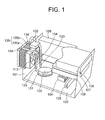
- FIG. 1 is a perspective view of the electronic device to which the liquid cooling jacket according to the present invention is applied.
- FIG. 1 illustrates a desktop type personal computer.
- a mother board 102 is near the bottom face within a casing 101.
- a CPU 103 as a heating element
- a chip set 104 As a heating element
- a memory 105 On the mother board 102 mounted are a CPU 103 as a heating element, a chip set 104, and a memory 105.
- An HDD 106, an FDD 107, and a CD-ROM drive 108 are installed as external storage devices within the casing 101.
- a liquid cooling jacket 131 according to the present invention is attached to the CPU 103.
- This liquid cooling jacket 131 is made of metal superior in heat transfer, such as copper or aluminum.
- the contact surface with the CPU 103 is bonded under pressure with thermal compound or highly heat-conductive silicone rubber being interposed, thereby a structure is realized in which heat generated in the CPU 103 is efficiently transmitted to the liquid cooling jacket 131.
- Coolant is made to flow within the liquid cooling jacket 131 by a pump 132 to realize a structure for transmitting heat to the coolant.
- a heat sink 135 as a radiator unit is disposed outside the rear face of the casing 101.
- the heat sink 135 is made up of a base 135a and fins 135b.
- the coolant flows within the base 135a to realize a structure for transmitting the heat of the coolant to the whole of the base 135a.
- the base 135a has a mechanism for keeping a constant liquid quantity. That is, the base 135a also functions as a reserve tank for the coolant.
- the fins 135b are arranged so as to face the rear face of the casing. That is, the wind from a fan 113 blows on the fins 135b.
- the fan 113 attached to the rear face of the casing 101 is disposed so as to be opposite to the heat sink 135 and the wind from the fan 113 blows directly to the fins 135b. More specifically, the fan 113 is an axial fan whose suction side is near the inside of the casing 101 and whose discharge side is near the heat sink 135. A power supply 109 is adjacent to the fan 113.
- Tubes 133 and metallic pipes 134 connect the liquid cooling jacket 131 and the heat sink 135 to each other.
- the tubes 133 and the metallic pipes 134 allow the coolant to flow therein and thus they form a heat transmission path between the liquid cooling jacket 131 and the heat sink 135.
- the whole piping is mainly made of the metallic pipes 134 and the rubber tubes 133 are partially used. Because the tubes 133 can be bent, maintenance such as replacement of the CPU 103 is easy. That is, the liquid cooling jacket 131 can be detached from the CPU 103 without detaching the fan 113 and the heat sink 135. In addition, by using the metallic pipes 134 for the part of the piping other than the tubes 133, moisture permeation is suppressed.
- the flowing route of the coolant is from the pump 132 through the liquid cooling jacket 131 and the heat sink 135 to the pump 132.
- the pump 132 sucks the coolant after passing through the heat sink 135 and discharges the coolant to the liquid cooling jacket 131. Therefore, the cooled coolant flows in the pump 132 and thereby the pump 132 is prevented from being heated.
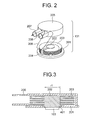
- FIG. 2 is an exploded view of the liquid cooling jacket according to the present invention.
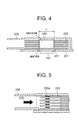
- FIG. 3 is an explanatory view for explaining heat conduction to radiating fins of the liquid cooling jacket according to the present invention.
- FIG. 4 is an explanatory view for explaining an example in which a heat pipe is used as a post of the liquid cooling jacket according to the present invention.
- FIG. 5 is an explanatory view for explaining the flow of the coolant of the liquid cooling jacket according to the present invention.
- FIG. 6 is an explanatory view for explaining a shape for decreasing the diameter of an inlet or outlet of the liquid cooling jacket according to the present invention.
- FIG. 7 is an explanatory view for explaining another shape for decreasing the diameter of the inlet or outlet of the liquid cooling jacket according to the present invention.
- the liquid cooling jacket is made up of a base 201 bonded to the heating element 103, a post 202 standing vertically to the base 201, radiating fins 203 attached to the post 202 so as to be parallel to the base 201, a partition 204 filling up the intervals between the radiating fins at a predetermined width, and a case 205 that surrounds the post 202 and the radiating fins 203, is bonded to the base 201, and is provided with an inlet 206 and an outlet 207 for the coolant.
- the base 201 is in contact with the heating element with high flatness.
- the base 201 has a function of keeping the post 202 vertical and a function of ensuring watertightness with the case 205.
- a material high in heat conductivity such as copper, may be used.
- the base 201 may be formed integrally with the post 202. Otherwise, a structure may be adopted in which the post 202 penetrates the base 201 to be in direct contact with the heating element 103. In this case, because the heat conductivity of the base 201 is not important, a cheap material can be used.
- the post 202 vertically transmits heat from the heating element 103 and further transmits the heat to the radiating fins 203.
- the base 201 horizontally spreads heat, as shown in the heat spread 303 in FIG. 21, to transmit heat to each radiating fin 302.
- the base thickness has a limit by the influence of weight and height. Actually, the thickness is about 7 mm at the maximum and thus the thermal resistance is high. Therefore, the heat spread 303 is limited to an area in the vicinity of the heating element 103 and heat cannot be transmitted to the end flat plates 302a.
- heat conduction to each radiating fin 203 is born by the post 202.
- This post 202 is columnar and thick as a diameter r1 of about 30 mm, and thus the thermal resistance is low. Further, even at the top portion of the post 202, sufficient cooling can be performed because the height of the post 202 is approximately equal to the height of the inlet 206 and outlet 207 for the coolant. For example, in case that the inlet 206 and outlet 207 each have an inner diameter of 7 ⁇ mm and an outer diameter of 9 ⁇ mm, the post 202 may have a height of about 10 mm. Because the distance from the heating element 103 is small, heat 401 from the heating element 103 can be sufficiently transmitted.
- a heat pipe 209 may be used as the post 202. If the post 202 has a function of the heat pipe 209, a structure other than that illustrated in FIG. 4 is also possible.
- the radiating fins 203 are attached to the post 202 in a positional relation of being parallel to the base 201.
- the radiating fins 203 each have a shape concentric with the post 202.
- the radiating fins 203 have a function of transmitting heat from the post 202 to the coolant.
- the surface of each radiating fin 203 may have protrusions, openings, or the like.
- the post 202 is columnar and the radiating fins 203 are concentric with the post 202.
- the shapes of the post 202 and radiating fins 203 are not limited to these. Other shapes may be adopted.
- the radiating fins 203 of this embodiment must be designed differently from fins for air cooling. More specifically, air and liquid widely differs from each other in heat capacity. For example, the heat capacity of water is 89 times of that of air. That is, because the coolant as liquid is superior to air in ability of taking heat off, the fins can be small-sized in comparison with those for air cooling.
- fins for liquid cooling require high heat conductive ability.
- each interval between the radiating fins is wide in comparison with the thickness of each radiating fin because a large amount of air is required for discharging heat.
- each radiating fin is preferably thick to increase the heat conductive ability of the fin itself.
- each interval between the radiating fins is narrow in comparison with the thickness of each radiating fin, for example, the thickness of each radiating fin 203 is 2 mm and each interval between the fins is 1 mm.
- the radiating fins are provided with a partition 204 filling up the intervals between the radiating fins at a predetermined width.
- This partition 204 is for forming a passage for the coolant 208 as illustrated in FIG. 2. Because the liquid flow is thereby turned back, the inlet 206 and the outlet 207 can be arranged parallel to each other. This can improve convenience on piping. If the liquid flow need not be turned back, the partition 204 may be omitted so that the inlet 206 and the outlet 207 are disposed in opposition to each other.
- the inlet 206 and the outlet 207 have a function of making the coolant flow evenly among the intervals between the radiating fins.
- the size of each of the inlet 206 and outlet 207 is substantially equal to the height of the radiating fins 203.
- the shape of the inlet 206 or outlet 207 may be tapered after the insertion portion of the tube 133. Otherwise, as illustrated in FIG. 7, the inlet 206 or outlet 207 may be disposed at an angle with the radiation fins 203 and the passage between the inlet 206 or outlet 207 and the radiation fins 203 is connected by an inclined wall.
- FIGS. 8 and 9 are explanatory views for explaining the structure of the liquid cooling jacket according to the present invention in consideration of assembling.
- FIG. 10 is an explanatory view for explaining the shape of the partition of the liquid cooling jacket according to the present invention.
- the base 201, the post 202, and the radiating fins 203 are integrally formed by rotary lathe processing.
- a threaded portion 701 by being subjected to threading processing On the other hand, the case 205 also has been subjected to the corresponding threading processing.
- a groove 801 in which the partition 204 is fitted is provided between the inlet 206 and outlet 207 for the coolant.
- the partition 204 has the shape as illustrated in FIG. 10, which has grooves 901 to be fitted on the respective radiating fins 203.
- the partition 204 can slide as shown by arrows 802 in FIG. 9 in a state of being fitted on the radiating fins 203.
- the coefficient of thermal expansion of the partition 204 may be set at a value different from that of the coefficient of thermal expansion of the radiating fins. This measure makes it possible that the partition groove 901 is processed such that the partition 204 and the radiating fins 203 can be easily moved upon assembling, and the partition groove is narrowed by heat of the coolant so that the partition 204 and the radiating fins 203 can be completely brought into close contact with each other upon actual cooling.
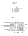
- FIG. 11 is a view illustrating an example in which liquid cooling jackets according to the present invention are put in layers to further improve the performance.
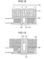
- FIG. 12 is a view illustrating an example in which an air-cooling heat sink and a fan are put in layers on a liquid cooling jacket according to the present invention to further improve the performance.
- FIG. 13 is a view illustrating an example in which the performance is intended to be further improved by an air-cooling heat sink formed integrally with a liquid cooling jacket according to the present invention.
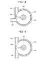
- FIGS. 14 and 15 are views illustrating examples in each of which the arrangement of the inlet and outlet of a liquid cooling jacket according to the present invention is changed.
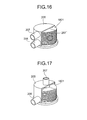
- FIGS. 16 and 17 are views illustrating examples in each of which a spiral radiating fin is used in a liquid cooling jacket according to the present invention.
- the heat transfer coefficient can be further improved by putting a liquid cooling jacket on another liquid cooling jacket. More specifically, the post 202 having received heat from the heating element 103 is in contact with a top plate 1001 of the case 205 and thus the former is thermally connected to the latter. Therefore, the heat from the heating element 103 is transmitted to the post 202 of the upper jacket as shown by an arrow 1002. Thus, because the heat from the heating element 103 is transmitted to the coolant by a plurality of jackets, the heat transfer coefficient is further improved.
- the cooling ability can be intended to be further improved by attaching an air-cooling heat sink 1101 and a fan 1102.
- the post 202 may penetrate the top plate 1001 to be formed integrally with an air-cooling heat sink 1201.
- the direction of one or both of the inlet and outlet can be changed.
- the coolant can be turned without using the partition 204.
- the coolant having entered from the inlet 206 is made to spirally flow and discharged from the upper outlet 207.
- the position of the outlet 207 suffices if it is in the upper portion of the case 205.
- the outlet 207 may be at a position denoted by a reference numeral 207' shown in FIG. 16, or may be on the top face of the case 205 as illustrated in FIG. 17.
- the liquid cooling jacket comprises a base 201 bonded to a heating element 103, a post 202 standing vertically to the base 201, a plurality of radiating fins 203 attached to the post 202 and arranged so as to be parallel to the base 201, a partition 204 filling up the intervals between the plurality of radiating fins 203 at a predetermined width, and a case 205 which surrounds the post 202 and the radiating fins 203 and is bonded to the base 201 and to which an inlet 206 and an outlet 207 are attached at positions symmetrical in relation to the partition 204.
- the plurality of radiating fins 203 are arranged at the intervals each of which is narrow in comparison with the thickness of each radiating fin 203. Therefore, because the coolant flow within the liquid cooling jacket ensures a plurality of passages, the passage resistance is low. In addition, by setting the size of each of the inlet and outlet for the coolant to be substantially equal to the height of the arranged radiating fins 203, the flow rates on the radiating fins 203 can be even.
- the post 202 for transmitting heat to each radiating fin 203 is thick and the height of the post 202 can be at a small distance from the base 201 in contact with the heating element 103, the coefficient of thermal conductivity is high.
- the inlet and outlet for the coolant can be arranged in a row and thus convenience on piping is superior.
Landscapes
- Engineering & Computer Science (AREA)
- Physics & Mathematics (AREA)
- Thermal Sciences (AREA)
- Mechanical Engineering (AREA)
- General Engineering & Computer Science (AREA)
- Life Sciences & Earth Sciences (AREA)
- Sustainable Development (AREA)
- Microelectronics & Electronic Packaging (AREA)
- Cooling Or The Like Of Electrical Apparatus (AREA)
- Cooling Or The Like Of Semiconductors Or Solid State Devices (AREA)
Applications Claiming Priority (2)
| Application Number | Priority Date | Filing Date | Title |
|---|---|---|---|
| JP2003349701 | 2003-10-08 | ||
| JP2003349701A JP3771233B2 (ja) | 2003-10-08 | 2003-10-08 | 液冷ジャケット |
Publications (2)
| Publication Number | Publication Date |
|---|---|
| EP1524692A2 true EP1524692A2 (de) | 2005-04-20 |
| EP1524692A3 EP1524692A3 (de) | 2009-12-23 |
Family
ID=34373532
Family Applications (1)
| Application Number | Title | Priority Date | Filing Date |
|---|---|---|---|
| EP04005471A Withdrawn EP1524692A3 (de) | 2003-10-08 | 2004-03-08 | Flüssigkeitsdurchströmter Kühlmantel zum Kühlen einer elektronischen Vorrichtung |
Country Status (6)
| Country | Link |
|---|---|
| US (1) | US7021367B2 (de) |
| EP (1) | EP1524692A3 (de) |
| JP (1) | JP3771233B2 (de) |
| KR (1) | KR100610293B1 (de) |
| CN (1) | CN100385653C (de) |
| TW (1) | TWI302242B (de) |
Cited By (3)
| Publication number | Priority date | Publication date | Assignee | Title |
|---|---|---|---|---|
| WO2005088713A1 (de) * | 2004-03-11 | 2005-09-22 | Hüttinger Elektronik Gmbh + Co. Kg | Kühleinrichtung |
| EP2559964A1 (de) * | 2011-08-15 | 2013-02-20 | Pierburg GmbH | Kühlvorrichtung für ein thermisch belastetes Bauteil |
| DE102016204895A1 (de) * | 2016-03-23 | 2017-09-28 | Phoenix Contact E-Mobility Gmbh | Leistungskontaktsystem für einen Ladestecker und/oder eine Ladebuchse, Ladestecker und Ladestation zur Abgabe elektrischer Energie an einen Empfänger elektrischer Energie |
Families Citing this family (44)
| Publication number | Priority date | Publication date | Assignee | Title |
|---|---|---|---|---|
| TWM267825U (en) * | 2004-11-03 | 2005-06-11 | Forward Electronics Co Ltd | Improved heat sink structure of liquid-cooling type heat sink device |
| JP2006286767A (ja) * | 2005-03-31 | 2006-10-19 | Hitachi Ltd | 冷却ジャケット |
| JP4266959B2 (ja) * | 2005-06-08 | 2009-05-27 | Necディスプレイソリューションズ株式会社 | 電子機器の冷却装置および投写型光学装置 |
| CN100499974C (zh) * | 2005-08-10 | 2009-06-10 | 富准精密工业(深圳)有限公司 | 整合式液冷散热装置 |
| JP4593438B2 (ja) * | 2005-10-24 | 2010-12-08 | 富士通株式会社 | 電子機器および冷却モジュール |
| TWM289878U (en) * | 2005-11-11 | 2006-04-21 | Cooler Master Co Ltd | Heat-dissipation structure of water-cooling type parallel runner |
| US20080310105A1 (en) * | 2007-06-14 | 2008-12-18 | Chia-Chun Cheng | Heat dissipating apparatus and water cooling system having the same |
| KR100886951B1 (ko) * | 2007-07-12 | 2009-03-09 | 한국전기연구원 | 열전소자를 구비한 냉각장치 |
| US8746330B2 (en) | 2007-08-09 | 2014-06-10 | Coolit Systems Inc. | Fluid heat exchanger configured to provide a split flow |
| US9943014B2 (en) | 2013-03-15 | 2018-04-10 | Coolit Systems, Inc. | Manifolded heat exchangers and related systems |
| US9453691B2 (en) * | 2007-08-09 | 2016-09-27 | Coolit Systems, Inc. | Fluid heat exchange systems |
| US9496200B2 (en) | 2011-07-27 | 2016-11-15 | Coolit Systems, Inc. | Modular heat-transfer systems |
| TW200910068A (en) * | 2007-08-20 | 2009-03-01 | Asustek Comp Inc | Heat dissipation apparatus |
| JP5341549B2 (ja) * | 2009-02-19 | 2013-11-13 | 株式会社ティラド | ヒートシンク |
| US8000101B2 (en) * | 2009-07-23 | 2011-08-16 | Hewlett-Packard Development Company, L.P. | System and method for attaching liquid cooling apparatus to a chassis |
| CN203595658U (zh) | 2010-10-14 | 2014-05-14 | 诺瓦威夫科技公司 | 光室模块组件 |
| US9651488B2 (en) | 2010-10-14 | 2017-05-16 | Thermo Fisher Scientific (Bremen) Gmbh | High-accuracy mid-IR laser-based gas sensor |
| US20120103575A1 (en) * | 2010-11-03 | 2012-05-03 | Hon Hai Precision Industry Co., Ltd. | Cooling device |
| US20120305218A1 (en) * | 2011-06-01 | 2012-12-06 | Benjamin Masefield | Heat Sink |
| CN102819303A (zh) * | 2011-06-09 | 2012-12-12 | 鸿富锦精密工业(深圳)有限公司 | 计算机机箱 |
| US10365667B2 (en) | 2011-08-11 | 2019-07-30 | Coolit Systems, Inc. | Flow-path controllers and related systems |
| CN103827581A (zh) * | 2011-09-26 | 2014-05-28 | 普司科Led股份有限公司 | 光学半导体式发光装置 |
| TWM424749U (en) * | 2011-10-27 | 2012-03-11 | Enermax Technology Corp | Liquid-cooled heat exchange module improvement |
| US10364809B2 (en) | 2013-03-15 | 2019-07-30 | Coolit Systems, Inc. | Sensors, multiplexed communication techniques, and related systems |
| US12366870B2 (en) | 2013-03-15 | 2025-07-22 | Coolit Systems, Inc. | Flow-path controllers and related systems |
| US10415597B2 (en) | 2014-10-27 | 2019-09-17 | Coolit Systems, Inc. | Fluid heat exchange systems |
| US9818671B2 (en) * | 2015-02-10 | 2017-11-14 | Dynatron Corporation | Liquid-cooled heat sink for electronic devices |
| US10107303B2 (en) * | 2015-05-22 | 2018-10-23 | Teza Technologies LLC | Fluid cooled server and radiator |
| JP6482955B2 (ja) * | 2015-06-02 | 2019-03-13 | 昭和電工株式会社 | 液冷式冷却装置 |
| CA3013255A1 (en) * | 2017-01-18 | 2018-07-26 | Fujian Sanan Sino-Science Photobiotech Co., Ltd | An easily formed liquid cooling module of an led lamp |
| CN107425323B (zh) * | 2017-08-28 | 2022-07-05 | 深圳市沃尔新能源电气科技股份有限公司 | 一种插接母端子及应用该母端子的充电枪、充电枪用插座 |
| US10582650B2 (en) * | 2017-10-13 | 2020-03-03 | Arista Networks, Inc. | Power supply with interchangeable fan module |
| CN112205091B (zh) * | 2017-12-08 | 2024-03-22 | 株式会社Kmw | 电子元件的散热装置 |
| KR101990592B1 (ko) | 2018-05-28 | 2019-06-18 | 한국기계연구원 | 상변화 냉각모듈 및 이를 이용하는 배터리팩 |
| TWM575882U (zh) * | 2018-11-22 | 2019-03-21 | 訊凱國際股份有限公司 | 外接式水冷裝置 |
| KR102091698B1 (ko) | 2019-01-08 | 2020-03-20 | 한국기계연구원 | 상변화 냉각장치 및 상변화 냉각방법 |
| US11662037B2 (en) | 2019-01-18 | 2023-05-30 | Coolit Systems, Inc. | Fluid flow control valve for fluid flow systems, and methods |
| US11473860B2 (en) | 2019-04-25 | 2022-10-18 | Coolit Systems, Inc. | Cooling module with leak detector and related systems |
| US10874034B1 (en) * | 2019-11-05 | 2020-12-22 | Facebook, Inc. | Pump driven liquid cooling module with tower fins |
| EP4150216A4 (de) | 2020-05-11 | 2023-11-01 | Coolit Systems, Inc. | Flüssigkeitspumpeinheiten sowie zugehörige systeme und verfahren |
| US11725886B2 (en) | 2021-05-20 | 2023-08-15 | Coolit Systems, Inc. | Modular fluid heat exchange systems |
| JP7722080B2 (ja) * | 2021-09-10 | 2025-08-13 | 株式会社プロテリアル | コイル組立部材及びボイスコイルモータ |
| CN114485216B (zh) * | 2022-01-10 | 2023-06-23 | 中国科学院理化技术研究所 | 辐射翅片式换热器及自由活塞斯特林发电机 |
| US12200914B2 (en) | 2022-01-24 | 2025-01-14 | Coolit Systems, Inc. | Smart components, systems and methods for transferring heat |
Family Cites Families (21)
| Publication number | Priority date | Publication date | Assignee | Title |
|---|---|---|---|---|
| US4188996A (en) * | 1977-05-04 | 1980-02-19 | Ckd Praha, Oborovy Podnik | Liquid cooler for semiconductor power elements |
| JPS55123153A (en) * | 1979-03-16 | 1980-09-22 | Fujitsu Ltd | Semiconductor device |
| US4592415A (en) * | 1984-10-09 | 1986-06-03 | Howard Friedman | Thin flat heat exchanger and method of making same |
| JPS6243054A (ja) * | 1985-08-20 | 1987-02-25 | Oki Electric Ind Co Ltd | 真空装置 |
| JPS62274798A (ja) * | 1986-05-19 | 1987-11-28 | インタ−ナショナル ビジネス マシ−ンズ コ−ポレ−ション | ヒ−トシンク構造体 |
| JP2635914B2 (ja) * | 1993-08-18 | 1997-07-30 | カワソーテクセル株式会社 | 液冷抵抗器 |
| JP2833999B2 (ja) * | 1994-07-13 | 1998-12-09 | 日本電気株式会社 | Lsiの冷却モジュール |
| US5752474A (en) * | 1995-08-25 | 1998-05-19 | Kabushiki Kaisha Toyoda Jidoshokki Seisakusho | Viscous heater |
| US5763951A (en) * | 1996-07-22 | 1998-06-09 | Northrop Grumman Corporation | Non-mechanical magnetic pump for liquid cooling |
| US6167948B1 (en) * | 1996-11-18 | 2001-01-02 | Novel Concepts, Inc. | Thin, planar heat spreader |
| EP0889524A3 (de) * | 1997-06-30 | 1999-03-03 | Sun Microsystems, Inc. | Skalierbares und modulares Wärmesenke-Wärmerohr Kühlsystem |
| JPH11121667A (ja) * | 1997-10-20 | 1999-04-30 | Fujitsu Ltd | ヒートパイプ式冷却装置 |
| JP2000340727A (ja) | 1999-05-26 | 2000-12-08 | Nissan Motor Co Ltd | 電子部品の冷却構造 |
| US6199625B1 (en) * | 1999-06-11 | 2001-03-13 | Psc Computer Products, Inc. | Stackable heat sink for electronic components |
| US6796370B1 (en) * | 2000-11-03 | 2004-09-28 | Cray Inc. | Semiconductor circular and radial flow cooler |
| JP4634599B2 (ja) | 2000-11-30 | 2011-02-16 | 株式会社ティラド | 水冷ヒートシンク |
| DE20111305U1 (de) * | 2001-07-11 | 2002-01-31 | innovatek OS GmbH, 85084 Reichertshofen | Wasserkühlsystem zur Kühlung von CPU's incl. Halterung |
| US6707676B1 (en) * | 2002-08-30 | 2004-03-16 | Ehood Geva | Heat sink for automatic assembling |
| US6712128B1 (en) * | 2002-11-20 | 2004-03-30 | Thermal Corp. | Cylindrical fin tower heat sink and heat exchanger |
| DE20302201U1 (de) * | 2003-02-12 | 2003-04-24 | May, Stefan, 37077 Göttingen | Sequentiell umflossene Temperiereinrichtung |
| US6793009B1 (en) * | 2003-06-10 | 2004-09-21 | Thermal Corp. | CTE-matched heat pipe |
-
2003
- 2003-10-08 JP JP2003349701A patent/JP3771233B2/ja not_active Expired - Fee Related
-
2004
- 2004-03-03 TW TW093105571A patent/TWI302242B/zh not_active IP Right Cessation
- 2004-03-08 EP EP04005471A patent/EP1524692A3/de not_active Withdrawn
- 2004-03-09 KR KR1020040015680A patent/KR100610293B1/ko not_active Expired - Fee Related
- 2004-03-10 US US10/796,045 patent/US7021367B2/en not_active Expired - Lifetime
- 2004-03-10 CN CNB2004100282502A patent/CN100385653C/zh not_active Expired - Fee Related
Cited By (4)
| Publication number | Priority date | Publication date | Assignee | Title |
|---|---|---|---|---|
| WO2005088713A1 (de) * | 2004-03-11 | 2005-09-22 | Hüttinger Elektronik Gmbh + Co. Kg | Kühleinrichtung |
| EP2559964A1 (de) * | 2011-08-15 | 2013-02-20 | Pierburg GmbH | Kühlvorrichtung für ein thermisch belastetes Bauteil |
| DE102016204895A1 (de) * | 2016-03-23 | 2017-09-28 | Phoenix Contact E-Mobility Gmbh | Leistungskontaktsystem für einen Ladestecker und/oder eine Ladebuchse, Ladestecker und Ladestation zur Abgabe elektrischer Energie an einen Empfänger elektrischer Energie |
| DE102016204895B4 (de) * | 2016-03-23 | 2020-11-12 | Phoenix Contact E-Mobility Gmbh | Ladestecker mit einem Leistungskontaktsystem und Ladestation zur Abgabe elektrischer Energie an einen Empfänger elektrischer Energie |
Also Published As
| Publication number | Publication date |
|---|---|
| CN1606403A (zh) | 2005-04-13 |
| JP2005116815A (ja) | 2005-04-28 |
| TW200513832A (en) | 2005-04-16 |
| US20050077028A1 (en) | 2005-04-14 |
| KR100610293B1 (ko) | 2006-08-09 |
| CN100385653C (zh) | 2008-04-30 |
| US7021367B2 (en) | 2006-04-04 |
| EP1524692A3 (de) | 2009-12-23 |
| KR20050034526A (ko) | 2005-04-14 |
| TWI302242B (en) | 2008-10-21 |
| JP3771233B2 (ja) | 2006-04-26 |
Similar Documents
| Publication | Publication Date | Title |
|---|---|---|
| US7021367B2 (en) | Liquid cooling jacket | |
| US7516777B2 (en) | Cooling jacket | |
| US7753108B2 (en) | Liquid cooling device | |
| US7174738B2 (en) | Computer cooling apparatus | |
| US6725682B2 (en) | Computer cooling apparatus | |
| US20050173097A1 (en) | Liquid circulation type cooling system | |
| US20050067145A1 (en) | Liquid cooling module | |
| JP2009532871A (ja) | 冷却装置 | |
| US20080006037A1 (en) | Computer cooling apparatus | |
| EP3914991B1 (de) | Kühlsystem mit einer wärmetauscheinheit | |
| US20210018229A1 (en) | Composite water-cooling radiator structure | |
| JP2004295718A (ja) | 情報処理装置の液例システム | |
| EP1708263B1 (de) | Kühlmantel | |
| US20080289802A1 (en) | Radiator and cooling system | |
| US20250344343A1 (en) | Liquid-cooling devices, and systems, to cool multi-chip modules | |
| JP5667739B2 (ja) | ヒートシンクアセンブリ、半導体モジュール及び冷却装置付き半導体装置 | |
| US12309970B2 (en) | Water cooling radiator | |
| US20070097637A1 (en) | Heat dissipation device | |
| US20250338442A1 (en) | Nucleation surface treatment for thermal cooling | |
| TWM586876U (zh) | 複合水冷排結構 | |
| CN113347856B (zh) | 一种电子设备的散热装置 | |
| US20050039880A1 (en) | Computer cooling apparatus | |
| CN215187956U (zh) | 一种用于一电子装置的冷却系统 | |
| CN108022895A (zh) | 水冷排散热结构 | |
| KR20240175735A (ko) | 워터자켓 구조의 열 교환기 모듈 및 이를 포함하는 국소 발열부 냉각 시스템 |
Legal Events
| Date | Code | Title | Description |
|---|---|---|---|
| PUAI | Public reference made under article 153(3) epc to a published international application that has entered the european phase |
Free format text: ORIGINAL CODE: 0009012 |
|
| AK | Designated contracting states |
Kind code of ref document: A2 Designated state(s): AT BE BG CH CY CZ DE DK EE ES FI FR GB GR HU IE IT LI LU MC NL PL PT RO SE SI SK TR |
|
| AX | Request for extension of the european patent |
Extension state: AL LT LV MK |
|
| 17P | Request for examination filed |
Effective date: 20060331 |
|
| PUAL | Search report despatched |
Free format text: ORIGINAL CODE: 0009013 |
|
| AK | Designated contracting states |
Kind code of ref document: A3 Designated state(s): AT BE BG CH CY CZ DE DK EE ES FI FR GB GR HU IE IT LI LU MC NL PL PT RO SE SI SK TR |
|
| AX | Request for extension of the european patent |
Extension state: AL LT LV MK |
|
| RIC1 | Information provided on ipc code assigned before grant |
Ipc: F28F 3/12 20060101ALI20091118BHEP Ipc: F28F 3/02 20060101ALI20091118BHEP Ipc: F28D 15/02 20060101ALI20091118BHEP Ipc: H01L 23/427 20060101ALI20091118BHEP Ipc: H01L 23/367 20060101ALI20091118BHEP Ipc: H01L 23/473 20060101AFI20050302BHEP |
|
| AKX | Designation fees paid |
Designated state(s): DE |
|
| STAA | Information on the status of an ep patent application or granted ep patent |
Free format text: STATUS: THE APPLICATION IS DEEMED TO BE WITHDRAWN |
|
| 18D | Application deemed to be withdrawn |
Effective date: 20100624 |