EP1524437A2 - Ventilanordnung mit einstellbarer Funktion und Verfahren hierfür - Google Patents
Ventilanordnung mit einstellbarer Funktion und Verfahren hierfür Download PDFInfo
- Publication number
- EP1524437A2 EP1524437A2 EP20040105088 EP04105088A EP1524437A2 EP 1524437 A2 EP1524437 A2 EP 1524437A2 EP 20040105088 EP20040105088 EP 20040105088 EP 04105088 A EP04105088 A EP 04105088A EP 1524437 A2 EP1524437 A2 EP 1524437A2
- Authority
- EP
- European Patent Office
- Prior art keywords
- valve
- base plate
- function
- assembly
- grid plate
- Prior art date
- Legal status (The legal status is an assumption and is not a legal conclusion. Google has not performed a legal analysis and makes no representation as to the accuracy of the status listed.)
- Withdrawn
Links
- 238000000034 method Methods 0.000 title claims description 7
- 239000012530 fluid Substances 0.000 claims abstract description 9
- 230000011748 cell maturation Effects 0.000 claims description 12
- 230000004069 differentiation Effects 0.000 claims description 3
- 238000007599 discharging Methods 0.000 claims 2
- 238000004519 manufacturing process Methods 0.000 description 3
- 239000000463 material Substances 0.000 description 3
- 230000001276 controlling effect Effects 0.000 description 2
- 238000006243 chemical reaction Methods 0.000 description 1
- 239000013013 elastic material Substances 0.000 description 1
- 238000005516 engineering process Methods 0.000 description 1
- 238000012423 maintenance Methods 0.000 description 1
- 230000001105 regulatory effect Effects 0.000 description 1
- 239000003566 sealing material Substances 0.000 description 1
- 230000001360 synchronised effect Effects 0.000 description 1
Images

Classifications
-
- F—MECHANICAL ENGINEERING; LIGHTING; HEATING; WEAPONS; BLASTING
- F15—FLUID-PRESSURE ACTUATORS; HYDRAULICS OR PNEUMATICS IN GENERAL
- F15B—SYSTEMS ACTING BY MEANS OF FLUIDS IN GENERAL; FLUID-PRESSURE ACTUATORS, e.g. SERVOMOTORS; DETAILS OF FLUID-PRESSURE SYSTEMS, NOT OTHERWISE PROVIDED FOR
- F15B13/00—Details of servomotor systems ; Valves for servomotor systems
- F15B13/02—Fluid distribution or supply devices characterised by their adaptation to the control of servomotors
- F15B13/06—Fluid distribution or supply devices characterised by their adaptation to the control of servomotors for use with two or more servomotors
- F15B13/08—Assemblies of units, each for the control of a single servomotor only
- F15B13/0803—Modular units
- F15B13/0807—Manifolds
- F15B13/081—Laminated constructions
-
- F—MECHANICAL ENGINEERING; LIGHTING; HEATING; WEAPONS; BLASTING
- F15—FLUID-PRESSURE ACTUATORS; HYDRAULICS OR PNEUMATICS IN GENERAL
- F15B—SYSTEMS ACTING BY MEANS OF FLUIDS IN GENERAL; FLUID-PRESSURE ACTUATORS, e.g. SERVOMOTORS; DETAILS OF FLUID-PRESSURE SYSTEMS, NOT OTHERWISE PROVIDED FOR
- F15B13/00—Details of servomotor systems ; Valves for servomotor systems
- F15B13/02—Fluid distribution or supply devices characterised by their adaptation to the control of servomotors
- F15B13/06—Fluid distribution or supply devices characterised by their adaptation to the control of servomotors for use with two or more servomotors
- F15B13/08—Assemblies of units, each for the control of a single servomotor only
- F15B13/0803—Modular units
- F15B13/0807—Manifolds
- F15B13/0817—Multiblock manifolds
-
- F—MECHANICAL ENGINEERING; LIGHTING; HEATING; WEAPONS; BLASTING
- F15—FLUID-PRESSURE ACTUATORS; HYDRAULICS OR PNEUMATICS IN GENERAL
- F15B—SYSTEMS ACTING BY MEANS OF FLUIDS IN GENERAL; FLUID-PRESSURE ACTUATORS, e.g. SERVOMOTORS; DETAILS OF FLUID-PRESSURE SYSTEMS, NOT OTHERWISE PROVIDED FOR
- F15B13/00—Details of servomotor systems ; Valves for servomotor systems
- F15B13/02—Fluid distribution or supply devices characterised by their adaptation to the control of servomotors
- F15B13/06—Fluid distribution or supply devices characterised by their adaptation to the control of servomotors for use with two or more servomotors
- F15B13/08—Assemblies of units, each for the control of a single servomotor only
- F15B13/0803—Modular units
- F15B13/0821—Attachment or sealing of modular units to each other
-
- F—MECHANICAL ENGINEERING; LIGHTING; HEATING; WEAPONS; BLASTING
- F15—FLUID-PRESSURE ACTUATORS; HYDRAULICS OR PNEUMATICS IN GENERAL
- F15B—SYSTEMS ACTING BY MEANS OF FLUIDS IN GENERAL; FLUID-PRESSURE ACTUATORS, e.g. SERVOMOTORS; DETAILS OF FLUID-PRESSURE SYSTEMS, NOT OTHERWISE PROVIDED FOR
- F15B13/00—Details of servomotor systems ; Valves for servomotor systems
- F15B13/02—Fluid distribution or supply devices characterised by their adaptation to the control of servomotors
- F15B13/06—Fluid distribution or supply devices characterised by their adaptation to the control of servomotors for use with two or more servomotors
- F15B13/08—Assemblies of units, each for the control of a single servomotor only
- F15B13/0803—Modular units
- F15B13/0846—Electrical details
- F15B13/0857—Electrical connecting means, e.g. plugs, sockets
-
- F—MECHANICAL ENGINEERING; LIGHTING; HEATING; WEAPONS; BLASTING
- F15—FLUID-PRESSURE ACTUATORS; HYDRAULICS OR PNEUMATICS IN GENERAL
- F15B—SYSTEMS ACTING BY MEANS OF FLUIDS IN GENERAL; FLUID-PRESSURE ACTUATORS, e.g. SERVOMOTORS; DETAILS OF FLUID-PRESSURE SYSTEMS, NOT OTHERWISE PROVIDED FOR
- F15B13/00—Details of servomotor systems ; Valves for servomotor systems
- F15B13/02—Fluid distribution or supply devices characterised by their adaptation to the control of servomotors
- F15B13/06—Fluid distribution or supply devices characterised by their adaptation to the control of servomotors for use with two or more servomotors
- F15B13/08—Assemblies of units, each for the control of a single servomotor only
- F15B13/0803—Modular units
- F15B13/0875—Channels for electrical components, e.g. for cables or sensors
-
- F—MECHANICAL ENGINEERING; LIGHTING; HEATING; WEAPONS; BLASTING
- F15—FLUID-PRESSURE ACTUATORS; HYDRAULICS OR PNEUMATICS IN GENERAL
- F15B—SYSTEMS ACTING BY MEANS OF FLUIDS IN GENERAL; FLUID-PRESSURE ACTUATORS, e.g. SERVOMOTORS; DETAILS OF FLUID-PRESSURE SYSTEMS, NOT OTHERWISE PROVIDED FOR
- F15B13/00—Details of servomotor systems ; Valves for servomotor systems
- F15B2013/002—Modular valves, i.e. consisting of an assembly of interchangeable components
- F15B2013/006—Modular components with multiple uses, e.g. kits for either normally-open or normally-closed valves, interchangeable or reprogrammable manifolds
-
- Y—GENERAL TAGGING OF NEW TECHNOLOGICAL DEVELOPMENTS; GENERAL TAGGING OF CROSS-SECTIONAL TECHNOLOGIES SPANNING OVER SEVERAL SECTIONS OF THE IPC; TECHNICAL SUBJECTS COVERED BY FORMER USPC CROSS-REFERENCE ART COLLECTIONS [XRACs] AND DIGESTS
- Y10—TECHNICAL SUBJECTS COVERED BY FORMER USPC
- Y10T—TECHNICAL SUBJECTS COVERED BY FORMER US CLASSIFICATION
- Y10T137/00—Fluid handling
- Y10T137/0318—Processes
-
- Y—GENERAL TAGGING OF NEW TECHNOLOGICAL DEVELOPMENTS; GENERAL TAGGING OF CROSS-SECTIONAL TECHNOLOGIES SPANNING OVER SEVERAL SECTIONS OF THE IPC; TECHNICAL SUBJECTS COVERED BY FORMER USPC CROSS-REFERENCE ART COLLECTIONS [XRACs] AND DIGESTS
- Y10—TECHNICAL SUBJECTS COVERED BY FORMER USPC
- Y10T—TECHNICAL SUBJECTS COVERED BY FORMER US CLASSIFICATION
- Y10T137/00—Fluid handling
- Y10T137/5109—Convertible
- Y10T137/5283—Units interchangeable between alternate locations
Definitions
- the application relates to a valve assembly and a method for Functional differentiation of a valve arrangement according to the preambles of claims 1 and 7.
- Field of application of the invention is the field of multiway valves.
- valves depending on the requirements of different function LK: AH Characteristics, eg 2/2, 3/2 NO, 3/2 NC, 4/2 monostable, 4/2 bistable, 4/3 vented, 4/3 closed, 4/3 vented, 5/2 monostable, 5/2 bistable, 5/3 vented, 5/3 closed, 5/3 ventilated, etc. own.
- LK AH Characteristics, eg 2/2, 3/2 NO, 3/2 NC, 4/2 monostable, 4/2 bistable, 4/3 vented, 4/3 closed, 4/3 vented, 5/2 monostable, 5/2 bistable, 5/3 vented, 5/3 closed, 5/3 ventilated, etc. own.
- the different valve functions can be realized by means of different valve slides.
- valves In multi-way valves according to the prior art, the adjustment requires this Function characteristics a variety of different components, as appropriate, which valve function is desired.
- On the other side are the structural ones Requirements for valves in terms of geometric dimensions often the same because these are arranged side by side mounted on a base plate.
- a directional control valve is known in which by the twofold embodiment a valve plunger, a 5/2 multi-way valve in two 3/2 multiway valves can be transferred.
- the conversion is complicated and not all common valve types are adjustable.
- the invention is based on the basic idea that in a valve arrangement, comprising a base plate for supplying at least one multiway valve with pressurized fluid and removing pressurized fluid from the at least one multiway valve by suitable means Channels and openings and at least one multiway valve for controlling and pressurizing a pneumatic unit between base plate and multi-way valve a grid plate for the functional differentiation of the valve assembly and the determination of Valve arrangement function is arranged.
- the base plate and the at least one multiway valve can thus for all valve types be uniform.
- the function of the valve assembly is through the grid plate established.
- a grid plate according to the invention is any object that is capable of for the functional differentiation of a valve or the determination of a valve function at the to be used.
- the grid plate has over pneumatic pipes for the connection of ducts and / or openings in the Base plate and the at least one multiway valve for the functional differentiation of Valve arrangement and the determination of the valve assembly function. This way you can a functional differentiation can be achieved in a simple manner.
- the grid plate has electrical Lines and / or electrical devices for connection to and / or control of Base plate, the at least one multi-way valve or a pilot valve for Functional differentiation of the valve assembly and the determination of the valve function has. In this way, the functional differentiation can also be easily achieved and it There are further control options of the valve.
- the valve assembly is preferably by means of the grid plate on a function selected from a group containing: 2/2, 3/2 NO, 3/2 NC, 4/2 monostable, 4/2 bistable, 4/3 deaerated, 4/3 Completed, 4/3 vented, 5/2 monostable, 5/2 bistable, 5/3 vented, 5/3 closed, 5/3 ventilated, adjustable.
- the grid plate is exchangeable.
- Interchangeable in the sense of the invention means in particular that a change in the Functional differentiation of the valve without disassembly of the valve or the multi-way valve can be achieved. In this way it is possible in a simple way, even with already assembled and in use valves the functional characteristics of the Valve to change and so minimize downtime and / or production losses.
- the base plate and / or the at least one multi-way valve via means for positive or aligned Cooperation of the grid plate with the base plate and / or the at least one Multi-way valve.
- a valve assembly which is a base plate for supplying at least one multiway valve with pressurized fluid and removing pressurized fluid from the at least one multiway valve by suitable means Channels and openings and at least one multiway valve for controlling and pressurizing a pneumatic unit, characterized in that the functional adjustment of the valve assembly by selecting and / or replacing one between the base plate and the at least one a multi-way valve arranged grid plate takes place.
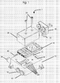
- Fig. 1 shows a valve assembly 1 according to the invention with two Ventilschiebem according to a first embodiment of the invention in exploded view.
- the valve assembly comprises a base plate 10 and a multi-way valve 20 and a pilot valve 40.
- Base plate 10, Multi-way valve 20 and pilot valve 40 are known from the prior art components Technology.
- the base plate has two working pressure lines 70 and 80 for Actuation of a pneumatic unit, not shown, for example a pneumatic cylinder with compressed air, a feed pressure line 60, a vent line 90 and a plurality of pneumatic lines 100, which at the top of the base plate 10th are arranged.
- the base plate includes Means 12 for the positive or aligned cooperation of the grid plate 30 with the base plate 10 and the at least one multi-way valve 20 in the form of bolts 12.
- the bolts can alternatively or additionally also be formed on the multiway valve be. In this way it is ensured that the grid plate is tight and fit between the base plate 10 and multi-way valve 20 can be arranged.
- Fig. 2a-d show a valve arrangement in which a 5/2 monostable multi-way valve is set.
- the grid plate 30 is preferred in the present and so far Embodiment designed so that it has at least one pneumatic line 120 features.
- the present embodiment has the Grid plate per valve slide via three pneumatic lines 120, the in selected manner some or all of the arranged in the base plate 10 pneumatic Lines 100 with selected lines 130 of the multi-way valve and ultimately with the Connect spool valves 110. Depending on which lines 100 with which lines 130 are connected, results in a different functional characteristic of the valve.
- valves of different functions can be set, including, but not limited to: 2/2, 3/2 NO, 3/2 NC, 4/2 monostable, 4/2 bistable, 4/3 vented, 4/3 Completed, 4/3 vented, 5/2 monostable, 5/2 bistable, 5/3 vented, 5/3 closed, 5/3 ventilated.
- Base plate 10 and multi-way valve 20 can be identical for all the different valves be designed. This results in a simplification in the production and maintenance The valves, too, will reduce the number of components needed for manufacturing different valves, since the function is determined by the grid plate and all other components may otherwise be identical.
- the grid plate consists of a 2-component part a hard plastic as a carrier and an elastic material as a sealing material (e.g., POM / AU).
- the pilot valve 40 shown in Fig. 1 is provided with lines or plugs 42 which in corresponding connections 44 fit.
- the grid plate in addition (not shown in the figures) via electrical lines and / or have electrical devices between the pilot valve 40 and the Ports 44 are connected and thus control the pilot valve 40.
- This is e.g. then from Advantage, when it is necessary that both valve spool of the multi-way valve 20 synchronously must be pressed. This can then by an appropriate circuit on the Grid plate can be ensured. Is a synchronous actuation of the valve slide is not necessary, then another circuit can be selected when using another grid plate be - or the electrical lines are also simply omitted.
- the Base plate 10 and / or the multi-way valve 20 can by electrical lines and / or devices in the grid plate 30 can be controlled and regulated.
- the grid plate is replaceable. This can e.g. happen that the grid plate is simply pushed out sideways. By inserting another grid plate, one valve can easily be replaced with another Function can be set.
- valve assembly has two valve spools.
- grid plates are conceivable through which only a valve spool or more than two valve spools are functionally adjustable.
Landscapes
- Engineering & Computer Science (AREA)
- Physics & Mathematics (AREA)
- Fluid Mechanics (AREA)
- Mechanical Engineering (AREA)
- General Engineering & Computer Science (AREA)
- Valve Housings (AREA)
- Fluid-Driven Valves (AREA)
- Sliding Valves (AREA)
- Fluid-Pressure Circuits (AREA)
Abstract
Description
charakteristika, z.B. 2/2, 3/2 NO, 3/2 NC, 4/2 monostabil, 4/2 bistabil, 4/3 entlüftet, 4/3 abgeschlossen, 4/3 belüftet, 5/2 monostabil, 5/2 bistabil, 5/3 entlüftet, 5/3 abgeschlossen, 5/3 belüftet etc. besitzen. Es können beispielsweise bei Schieberventilen durch unterschiedliche Ventilschieber die unterschiedlichen Ventilfunktionen realisiert werden.
- Fig. 1
- eine erfindungsgemäße Ventilanordnung mit zwei Ventilschiebem in Explosionsdarstellung;
- Fig.2a
- eine erfindungsgemäße Ventilanordnung mit einer anderen Rasterplatte (ansonsten baulich gleich) in Seitenansicht;
- Fig.2b
- die Ventilanordnung aus Fig. 2a mit einer anderen Rasterplatte in einer horizontalen Schnittansicht entlang Linie A-A aus Fig. 2d;
- Fig.2c
- die Ventilanordnung aus Fig. 2a in einer vertikalen Schnittansicht entlang Linie C-C aus Fig. 2b; sowie
- Fig.2d
- die Ventilanordnung aus Fig. 2a in einer vertikalen Schnittansicht entlang Linie B-B aus Fig. 2b.
- 10
- Grundplatte
- 12
- Bolzen
- 20
- Mehrwegeventil
- 30
- Rasterplatte
- 40
- Pilotventil
- 42
- Leitung/Stecker
- 44
- Anschlüsse
- 50
- Schrauben
- 60
- Speisedruckleitung
- 70
- Arbeitsdruckleitung
- 80
- Arbeitsdruckleitung
- 90
- Entlüftungsleitung
- 100
- pneumatische Leitungen
- 110
- Ventilschieber
- 120
- pneumatische Leitung
Claims (8)
- Ventilanordnung, umfassend eine Grundplatte (10) zum Beliefern mindestens eines Mehrwegeventils mit Druckfluid und Abführen von Druckfluid von dem mindestens einen Mehrwegeventil durch geeignete Kanäle und Öffnungen und mindestens ein Mehrwegeventil (20) zum Steuern und Beaufschlagen eines pneumatischen Aggregates,
dadurch gekennzeichnet, dass zwischen Grundplatte (10) und Mehrwegeventil (20) eine Rasterplatte (30) für die Funktionsdifferenzierung der Ventilanordnung und die Festlegung der Ventilanordnungsfunktion angeordnet ist. - Ventilanordnung nach Anspruch 1,
dadurch gekennzeichnet, dass die Rasterplatte (30) über pneumatische Leitungen für die Verbindung von Kanälen und/oder Öffnungen in der Grundplatte (10) und des mindestens einen Mehrwegeventils (20) für die Funktionsdifferenzierung der Ventilanordnung und die Festlegung der Ventilanordnungsfunktion verfügt. - Ventilanordnung nach Anspruch 1 oder 2,
dadurch gekennzeichnet, dass die Rasterplatte (30) über elektrische Leitungen und/oder elektrische Vorrichtungen für die Verbindung mit und/oder Steuerung der Grundplatte (10), des mindestens einen Mehrwegeventils (20) oder eines Pilotventils (40) für die Funktionsdifferenzierung der Ventilanordnung und die Festlegung der Ventilfunktion verfügt. - Ventilanordnung nach einem der Ansprüche 1 bis 3,
dadurch gekennzeichnet, dass die Ventilanordnung mittels der Rasterplatte (30) auf eine Funktion, ausgewählt aus einer Gruppe enthaltend: 2/2, 3/2 NO, 3/2 NC, 4/2 monostabil, 4/2 bistabil, 4/3 entlüftet, 4/3 abgeschlossen, 4/3 belüftet, 5/2 monostabil, 5/2 bistabil, 5/3 entlüftet, 5/3 abgeschlossen, 5/3 belüftet, einstellbar ist. - Ventilanordnung nach einem der Ansprüche 1 bis 4,
dadurch gekennzeichnet, dass die Rasterplatte (30) austauschbar ist. - Ventilanordnung nach einem der Ansprüche 1 bis 5,
dadurch gekennzeichnet, dass die Grundplatte (10) und/oder das mindestens eine Mehrwegeventil (20) über Mittel zum formschlüssigen oder fluchtenden Zusammenwirken der Rasterplatte mit der Grundplatte (10) und/oder des mindestens einen Mehrwegeventils (20) verfügen. - Verfahren zur Funktionseinstellung eines Ventilanordnung, welches eine Grundplatte (10) zum Beliefern mindestens eines Mehrwegeventils mit Druckfluid und Abführen von Druckfluid von dem mindestens einen Mehrwegeventil durch geeignete Kanäle und Öffnungen und mindestens ein Mehrwegeventil (20) zum Steuern und Beaufschlagen eines pneumatischen Aggregates,
dadurch gekennzeichnet, dass die Funktionseinstellung der Ventilanordnung durch Auswahl und/oder Auswechseln einer zwischen der Grundplatte (10) und des mindestens einen Mehrwegeventils (20) angeordneten Rasterplatte (30) erfolgt. - Verfahren nach Anspruch 7,
dadurch gekennzeichnet, dass die Ventilanordnung auf eine Funktion, ausgewählt aus einer Gruppe enthaltend: 2/2, 3/2 NO, 3/2 NC, 4/2 monostabil, 4/2 bistabil, 4/3 entlüftet, 4/3 abgeschlossen, 4/3 belüftet, 5/2 monostabil, 5/2 bistabil, 5/3 entlüftet, 5/3 abgeschlossen, 5/3 belüftet, eingestellt werden kann.
Applications Claiming Priority (2)
| Application Number | Priority Date | Filing Date | Title |
|---|---|---|---|
| DE10347936 | 2003-10-15 | ||
| DE2003147936 DE10347936B4 (de) | 2003-10-15 | 2003-10-15 | Ventilanordnung mit einstellbarer Funktion und Verfahren hierfür |
Publications (2)
| Publication Number | Publication Date |
|---|---|
| EP1524437A2 true EP1524437A2 (de) | 2005-04-20 |
| EP1524437A3 EP1524437A3 (de) | 2005-08-24 |
Family
ID=34353418
Family Applications (1)
| Application Number | Title | Priority Date | Filing Date |
|---|---|---|---|
| EP20040105088 Withdrawn EP1524437A3 (de) | 2003-10-15 | 2004-10-15 | Ventilanordnung mit einstellbarer Funktion und Verfahren hierfür |
Country Status (3)
| Country | Link |
|---|---|
| US (1) | US7357141B2 (de) |
| EP (1) | EP1524437A3 (de) |
| DE (1) | DE10347936B4 (de) |
Cited By (4)
| Publication number | Priority date | Publication date | Assignee | Title |
|---|---|---|---|---|
| WO2008064755A1 (de) * | 2006-11-28 | 2008-06-05 | Festo Ag & Co. Kg | Ventileinrichtung |
| WO2020094164A1 (de) * | 2018-11-08 | 2020-05-14 | Dürr Somac GmbH | Vorrichtung zur befüllung von behältern mit betriebsstoffen an montagelinien der automobilindustrie |
| EP4083442A1 (de) * | 2021-04-30 | 2022-11-02 | ABB Schweiz AG | Dielektrischer elastomeraktuator zur steuerung eines ventilpositionierers mit pneumatischem ausgang |
| DE102022001507A1 (de) | 2022-04-29 | 2023-11-02 | Dürr Somac GmbH | Verbindungshülse für hydraulische und pneumatische Baugruppen |
Families Citing this family (6)
| Publication number | Priority date | Publication date | Assignee | Title |
|---|---|---|---|---|
| FR2901851B1 (fr) * | 2006-06-02 | 2010-11-19 | Parker Hannifin France Holding | Ilot pour distibuteurs pneumatiques |
| DE102006060923A1 (de) * | 2006-12-20 | 2008-06-26 | Testo Ag | Ventilblock |
| USD854656S1 (en) * | 2016-05-19 | 2019-07-23 | Nagano Keiki Co., Ltd. | Fluid controller |
| DE102017117335B4 (de) * | 2017-07-31 | 2024-12-05 | Bürkert Werke GmbH & Co. KG | Betätigungseinheit für ein Prozessventil sowie Prozessventil |
| DE102022121840B3 (de) * | 2022-08-30 | 2024-01-25 | Schaeffler Technologies AG & Co. KG | Hydrauliksteuerung in Plattenbauweise |
| DE102022004464A1 (de) * | 2022-11-29 | 2024-05-29 | Dürr Somac GmbH | Baueinheit zur Ausgestaltung einer Schnittstelle für einen Befülladapter zur Befüllung von Fahrzeugen |
Citations (1)
| Publication number | Priority date | Publication date | Assignee | Title |
|---|---|---|---|---|
| DE9421326U1 (de) | 1994-11-11 | 1995-08-31 | Mannesmann AG, 40213 Düsseldorf | Wegeventil mit einem X/2-Wegeventilkörper |
Family Cites Families (10)
| Publication number | Priority date | Publication date | Assignee | Title |
|---|---|---|---|---|
| DE36469C (de) | haniel & lueg in Düsseldorf-Grafenberg | Caps-Einrichtung | ||
| DD36469A3 (de) * | 1962-08-30 | 1965-04-26 | ||
| DE2033736C3 (de) * | 1970-07-08 | 1978-03-30 | Klaus 7300 Esslingen Huegler | Universalsteuerblock für flüssige oder gasförmige Medien |
| DE4004834C2 (de) * | 1990-02-16 | 1996-06-13 | Festo Kg | Ventilbaugruppe |
| DE4037353C1 (de) * | 1990-11-20 | 1992-03-12 | Mannesmann Ag, 4000 Duesseldorf, De | |
| DE4226539A1 (de) * | 1992-08-11 | 1994-02-17 | Bosch Gmbh Robert | Elektropneumatische Ventilbaugruppe |
| DE4409667C1 (de) | 1994-03-15 | 1995-08-24 | Mannesmann Ag | Wegeventilanordnung mit Wegeventil und Grundplatte |
| GB2301167A (en) | 1995-03-14 | 1996-11-27 | Elizabeth Mary Shansonga | System valve |
| DE19954855C1 (de) * | 1999-11-15 | 2001-04-05 | Siemens Ag | System zur automatisierten Behandlung von Fluiden, mit einanderreihbaren, austauschbaren Prozeßmodulen |
| DE10204250A1 (de) * | 2002-02-02 | 2003-08-14 | Bosch Gmbh Robert | Mehrfachventilanordnung für strömende Medien |
-
2003
- 2003-10-15 DE DE2003147936 patent/DE10347936B4/de not_active Expired - Lifetime
-
2004
- 2004-10-12 US US10/962,961 patent/US7357141B2/en not_active Expired - Fee Related
- 2004-10-15 EP EP20040105088 patent/EP1524437A3/de not_active Withdrawn
Patent Citations (1)
| Publication number | Priority date | Publication date | Assignee | Title |
|---|---|---|---|---|
| DE9421326U1 (de) | 1994-11-11 | 1995-08-31 | Mannesmann AG, 40213 Düsseldorf | Wegeventil mit einem X/2-Wegeventilkörper |
Cited By (4)
| Publication number | Priority date | Publication date | Assignee | Title |
|---|---|---|---|---|
| WO2008064755A1 (de) * | 2006-11-28 | 2008-06-05 | Festo Ag & Co. Kg | Ventileinrichtung |
| WO2020094164A1 (de) * | 2018-11-08 | 2020-05-14 | Dürr Somac GmbH | Vorrichtung zur befüllung von behältern mit betriebsstoffen an montagelinien der automobilindustrie |
| EP4083442A1 (de) * | 2021-04-30 | 2022-11-02 | ABB Schweiz AG | Dielektrischer elastomeraktuator zur steuerung eines ventilpositionierers mit pneumatischem ausgang |
| DE102022001507A1 (de) | 2022-04-29 | 2023-11-02 | Dürr Somac GmbH | Verbindungshülse für hydraulische und pneumatische Baugruppen |
Also Published As
| Publication number | Publication date |
|---|---|
| DE10347936B4 (de) | 2007-09-27 |
| US7357141B2 (en) | 2008-04-15 |
| US20050081915A1 (en) | 2005-04-21 |
| EP1524437A3 (de) | 2005-08-24 |
| DE10347936A1 (de) | 2005-05-19 |
Similar Documents
| Publication | Publication Date | Title |
|---|---|---|
| DE60301746T2 (de) | Pneumatikventilgruppe mit einfacher Installierung und einfacher Wartung | |
| DE69511368T2 (de) | Einrichtung für Wegeventile | |
| EP1013940B1 (de) | Ventilanordnung | |
| EP0968372B1 (de) | Ventilanordnung | |
| DE2730287B2 (de) | VentUblockJür eine Glasformmaschine | |
| DE2033736A1 (de) | Umversalsteuerblock fur flussige oder gasförmige Medien | |
| EP3296602B1 (de) | Fluidverteilervorrichtung | |
| EP1524437A2 (de) | Ventilanordnung mit einstellbarer Funktion und Verfahren hierfür | |
| DE212016000111U1 (de) | Magnetventilsystem mit modularen Basen | |
| DE1774982A1 (de) | Pneumatischer lochstreifenabtaster | |
| DE112015001056B4 (de) | Vakuumpumpe | |
| DE60118296T2 (de) | Gesimsbiegemaschine mit pneumatischem Steuersystem zum Schnellspannen von Gesimsbiegewerkzeugen | |
| DE2509679C3 (de) | Steuerventil für die Druckluftbremsanlage eines Zugfahrzeuges | |
| EP2674652B1 (de) | Ventilanordnung mit Quetschventilen | |
| DE2637085C3 (de) | Vorrichtung zum Ausstoßen des Stanzabfalles oder Stanzteils mittels Druckluft | |
| EP0121849B1 (de) | Ventileinrichtung mit einstellbarer Funktion | |
| DE4016368A1 (de) | Spruehkopf einer spruehvorrichtung zum aufspruehen von fluessigkeiten, insbesondere trennmitteln | |
| DE102016206784B3 (de) | Fluidverteilervorrichtung | |
| EP0688958A1 (de) | Ventilanordnung | |
| WO2004027268A1 (de) | Mehrwegeventil | |
| DE102009054181A1 (de) | Ventilblock | |
| DE3600543A1 (de) | Drehbares waehlerventil | |
| DE29712709U1 (de) | Mehrwegeventil | |
| DE3244700A1 (de) | Vorrichtung zur verbesserung des hydrozyklonbetriebes | |
| DE2233851A1 (de) | Verfahren zur fernbetaetigung und elektrohydraulische vorrichtung zur ausfuehrung des verfahrens |
Legal Events
| Date | Code | Title | Description |
|---|---|---|---|
| PUAI | Public reference made under article 153(3) epc to a published international application that has entered the european phase |
Free format text: ORIGINAL CODE: 0009012 |
|
| AK | Designated contracting states |
Kind code of ref document: A2 Designated state(s): AT BE BG CH CY CZ DE DK EE ES FI FR GB GR HU IE IT LI LU MC NL PL PT RO SE SI SK TR |
|
| AX | Request for extension of the european patent |
Extension state: AL HR LT LV MK |
|
| PUAL | Search report despatched |
Free format text: ORIGINAL CODE: 0009013 |
|
| AK | Designated contracting states |
Kind code of ref document: A3 Designated state(s): AT BE BG CH CY CZ DE DK EE ES FI FR GB GR HU IE IT LI LU MC NL PL PT RO SE SI SK TR |
|
| AX | Request for extension of the european patent |
Extension state: AL HR LT LV MK |
|
| RIC1 | Information provided on ipc code assigned before grant |
Ipc: 7F 16K 27/00 B Ipc: 7F 15B 13/00 A |
|
| AKX | Designation fees paid | ||
| STAA | Information on the status of an ep patent application or granted ep patent |
Free format text: STATUS: THE APPLICATION IS DEEMED TO BE WITHDRAWN |
|
| 18D | Application deemed to be withdrawn |
Effective date: 20060225 |
|
| REG | Reference to a national code |
Ref country code: DE Ref legal event code: 8566 |