EP1524230B1 - Travelling service device for open-end spinning units of open-end spinning machines - Google Patents
Travelling service device for open-end spinning units of open-end spinning machines Download PDFInfo
- Publication number
- EP1524230B1 EP1524230B1 EP04077819A EP04077819A EP1524230B1 EP 1524230 B1 EP1524230 B1 EP 1524230B1 EP 04077819 A EP04077819 A EP 04077819A EP 04077819 A EP04077819 A EP 04077819A EP 1524230 B1 EP1524230 B1 EP 1524230B1
- Authority
- EP
- European Patent Office
- Prior art keywords
- thread
- trolley
- open
- spinning
- rotation
- Prior art date
- Legal status (The legal status is an assumption and is not a legal conclusion. Google has not performed a legal analysis and makes no representation as to the accuracy of the status listed.)
- Expired - Lifetime
Links
- 238000007383 open-end spinning Methods 0.000 title claims abstract description 25
- 238000009987 spinning Methods 0.000 claims abstract description 60
- 230000033001 locomotion Effects 0.000 description 15
- 210000000080 chela (arthropods) Anatomy 0.000 description 9
- 238000004804 winding Methods 0.000 description 9
- 230000015572 biosynthetic process Effects 0.000 description 5
- 238000000151 deposition Methods 0.000 description 3
- 238000000034 method Methods 0.000 description 3
- 230000002093 peripheral effect Effects 0.000 description 3
- 238000002360 preparation method Methods 0.000 description 3
- 230000000284 resting effect Effects 0.000 description 3
- 238000004140 cleaning Methods 0.000 description 2
- 238000000605 extraction Methods 0.000 description 2
- 238000003780 insertion Methods 0.000 description 2
- 230000037431 insertion Effects 0.000 description 2
- 238000004519 manufacturing process Methods 0.000 description 2
- 230000001133 acceleration Effects 0.000 description 1
- 230000009471 action Effects 0.000 description 1
- 230000006399 behavior Effects 0.000 description 1
- 230000005540 biological transmission Effects 0.000 description 1
- 238000004891 communication Methods 0.000 description 1
- 230000001419 dependent effect Effects 0.000 description 1
- 238000001514 detection method Methods 0.000 description 1
- 238000006073 displacement reaction Methods 0.000 description 1
- 230000000694 effects Effects 0.000 description 1
- 238000005516 engineering process Methods 0.000 description 1
- 238000007689 inspection Methods 0.000 description 1
- 230000009916 joint effect Effects 0.000 description 1
- 230000007246 mechanism Effects 0.000 description 1
- 230000010355 oscillation Effects 0.000 description 1
- 230000008569 process Effects 0.000 description 1
- 238000003908 quality control method Methods 0.000 description 1
- 230000006641 stabilisation Effects 0.000 description 1
- 238000011105 stabilization Methods 0.000 description 1
- 230000001360 synchronised effect Effects 0.000 description 1
- 230000009466 transformation Effects 0.000 description 1
- 238000009966 trimming Methods 0.000 description 1
- 238000011144 upstream manufacturing Methods 0.000 description 1
- 239000002699 waste material Substances 0.000 description 1
Images




Classifications
-
- D—TEXTILES; PAPER
- D01—NATURAL OR MAN-MADE THREADS OR FIBRES; SPINNING
- D01H—SPINNING OR TWISTING
- D01H13/00—Other common constructional features, details or accessories
- D01H13/04—Guides for slivers, rovings, or yarns; Smoothing dies
-
- B—PERFORMING OPERATIONS; TRANSPORTING
- B65—CONVEYING; PACKING; STORING; HANDLING THIN OR FILAMENTARY MATERIAL
- B65H—HANDLING THIN OR FILAMENTARY MATERIAL, e.g. SHEETS, WEBS, CABLES
- B65H57/00—Guides for filamentary materials; Supports therefor
- B65H57/28—Reciprocating or oscillating guides
-
- B—PERFORMING OPERATIONS; TRANSPORTING
- B65—CONVEYING; PACKING; STORING; HANDLING THIN OR FILAMENTARY MATERIAL
- B65H—HANDLING THIN OR FILAMENTARY MATERIAL, e.g. SHEETS, WEBS, CABLES
- B65H65/00—Securing material to cores or formers
-
- D—TEXTILES; PAPER
- D01—NATURAL OR MAN-MADE THREADS OR FIBRES; SPINNING
- D01H—SPINNING OR TWISTING
- D01H4/00—Open-end spinning machines or arrangements for imparting twist to independently moving fibres separated from slivers; Piecing arrangements therefor; Covering endless core threads with fibres by open-end spinning techniques
- D01H4/48—Piecing arrangements; Control therefor
- D01H4/50—Piecing arrangements; Control therefor for rotor spinning
-
- B—PERFORMING OPERATIONS; TRANSPORTING
- B65—CONVEYING; PACKING; STORING; HANDLING THIN OR FILAMENTARY MATERIAL
- B65H—HANDLING THIN OR FILAMENTARY MATERIAL, e.g. SHEETS, WEBS, CABLES
- B65H2701/00—Handled material; Storage means
- B65H2701/30—Handled filamentary material
- B65H2701/31—Textiles threads or artificial strands of filaments
Definitions
- Open-end spinning machines generally consist of a plurality of individual spinning units, aligned on the two sides of the machine, each of which is made up of a spinning rotor, which produces twisted thread from singularised fibres of a rove, and a collection unit that - with the prior quality control of yarn with the interposition of a yarn clearer between the two components - carries the yarn to wind onto a quill to form a cone.
- This cone is thus formed pulling and winding the yarn on its surface, being pulled into rotation by the roller below on which the cone in formation is rested.
- the yarn is wound in a spiral on the cone in rotation since the collection unit is equipped with a thread-guiding device that distributes the yarn on the outer surface of the cone with to and fro axial motion.
- the single spinning station 1 consists of the actual spinning unit 2 and the collection unit 3, the main components of which that lead to the transformation of the rove of fibres made to run parallel in the cone of wound yarn are briefly illustrated hereafter.
- the supply band or rove S is contained in a cylindrical vessel 4 where it is deposited in a double spiral.
- the rove S is supplied to the unit by a supply roller 5 passing through the funnel-shaped conveyor 6 and reaches the card 7, a rotating roller equipped with a toothed trimming that singularises the fibres of the rove S and conveys them by suction to the spinning rotor 8, which works in a vacuum.
- the singularised fibres are deposited in its peripheral throat by centrifugal effect; from here they are collected and picked up in the form of thread F, coming out axially from its central opening 9, receiving the twists from the rotation of the rotor itself in the path that runs between its inner throat and such an opening 9, thus generating the twisted thread F.
- the pulling back of the thread is carried out with a pair of opposite extraction cylinders 11 and 12 for gripping the thread F and actuated at a controlled speed according to the arrow a, thus determining the linear production of yarn, generally indicated in m/min.
- the yarn clearer 14 for controlling the quality of the yarn F can be placed before the cylinders 11/12.
- the thread F thus produced enters into the collection unit 3, passes by a sensor 15 of the presence of thread and meets a compensator 16 for compensating the variations in length of the path between the spinning unit 2 and the deposit point of the yarn F on the cone.
- the thread-guiding device 21 distributes the thread on the cone in formation moving transversally with to and fro motion according to the double arrow b, actuated by a motor 20 that commands a longitudinal shaft 22 in common with the other units of the spinning machine.
- the cone 25 collects the thread F and is held by the cone-holding arm 26 equipped with two idle tailstocks 27 that can be opened that go into engagement with the basic quill 28 of the cone.
- the cone in formation 25 is rested upon its actuation roller or collection cylinder 29.
- the required interventions are essentially of three types:
- Such interventions are carried out by separating the cone 25 from its actuation cylinder 29, stopping its motion and actuating the cone 25 or its quill 28 by an auxiliary actuation roller arranged on-board the service trolley.
- the automation trolley consists of a structure mobile along the sides of the machine, a communication system with the central control unit of the spinning machine and with the spinning unit that make up the machine, a translation and stopping system of the trolley in front of the units that require intervention.
- the mobile structure carries on-board both its control unit and the members or groups of members dedicated to the single or multiple operations of the various cycles, which can at various times be required and which can be managed by said control unit.
- the spinning unit after said failed attempts of the trolley, is left out of order (with a red light) requiring the inspection of the operator who must identify the cause of the negative outcome of the automatic intervention and manually take steps to prepare it for a further intervention, again to be conducted automatically, but this time with a positive outcome.
- the coordination of said members is therefore very important for controlling them as regards relative positions, time and speed phasing of such members both in relation to each other and with respect to the thread that is adopted, manipulated and exchanged by said members, controlling the successful completion of each step of the process.
- the present invention is relative to a device for controlling the positioning and the configuration of the path of the thread during the cycles operated by the service trolley for the open-end spinning machine.
- the purpose of the present invention is that of making a device for controlling the positioning of the thread during the intervention cycles of the trolley that overcomes the described drawbacks of the devices available in the state of the art and allows greater efficiency of the trolley and greater yield of the spinning machine to be obtained, reducing the idle time due to the repetition of interventions on the spinning units.
- FIG 1 illustrates the scheme of an open-end spinning station in its most significant components.
- Figure 2 illustrates a scheme of a service trolley C for an open-end spinning machine, in which the most significant members or groups that intervene in servicing as well as the device according to the invention for controlling and positioning the thread are indicated.
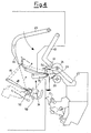
- Figures 4 to 7 show the relative positions of the members of the trolley C described up to now, according to a side view of the members of the trolley facing the spinning unit seen in profile, and illustrate some of the configurations and functions that the device according to the invention takes up and performs during the intervention cycles carried out by an automation trolley for open-end spinning machines.
- the device according to the invention is defined, in its essential components, in the first claim whereas its variants and preferred embodiments are specified and defined in the dependent claims.
- FIG. 2 shows an exploded view of the parallelepiped space inside the trolley C, in which its most significant members or groups for servicing the open-end spinning unit, including the device 31 according to the invention for controlling and positioning the thread are schematically indicated and, in particular, for the reattachment operations:
- the members of the trolley are managed by the trolley's own control unit, which in turn communicates with the central control unit of the spinning machine and with the individual spinning stations.
- the trolley control unit coordinates the steps of the intervention cycles, imparts the actuation commands to its members and receives the detection thereof from the relative sensors and end stop, checking the positive outcome or not of each step taking the measures to suit the case.
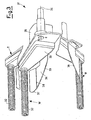
- Figure 3 illustrates a typical embodiment of the device 31 according to the invention for controlling and positioning the thread during the interventions of the trolley.
- the device is shown in perspective in its three typical positions at three different levels.
- the device 31 is installed to the left of the front of the trolley and consists of a worm screw 32, with a horizontal axis parallel to the front of the spinning machine, having one of the ends free and the other occupied by a cantilevered support arm 33. It can be lowered or raised by rotation of its support arm 33 that rotates about an axis 34, also with a horizontal axis parallel to the front of the spinning machine.
- a motor 35 for actuating the worm screw 32 in clockwise/anticlockwise rotation is mounted, whereas the arm 33 is also equipped with actuation in rotation to typically take up three controlled angular positions that determine the level of the axis of the screw 32: rest R, work W and tautness T according to the needs of the intervention cycles.
- a deviator plate 36 in the form of an asymmetrical hollow hut is fixed onto the inner part of the support arm 33, with an apex 37 and a fold 38 that lifts its external profile 39, farthest from the screw 32.
- the deviator plate 36 is thus integral with the worm screw 32 and follows it in its work and rest positions.
- the worm screw 32 has a diameter of 15-30 mm with rectangular threading with bevelled edges with a pith of 4-8 mm. It is equipped with actuation into commanded clockwise/anti-clockwise rotation with a speed in the order of hundreds of revs/min.
- the actuation motor 35 of the screw 32 can be a brushless motor driven in frequency by the trolley control unit to obtain angular positions and speeds that are controlled in the two directions of rotation.
- the actuation motor 35 of the screw 32 is a stepper motor driven in steps by the trolley control unit, again to obtain angular positions and speeds that are controlled in the two directions of rotation.
- the interruption of the thread is indicated by the sensor 15 of the presence of thread, at the entry of the collection unit 3.
- the peripheral control unit of the unit takes care of lifting the cone 25 disengaging it from its cylinder 29, braking the cone itself and requesting the intervention of the service trolley.
- the roller 5 for supplying the rove S to the spinning unit 2 is equally stopped.
- the other spinning units continue to work: the members with common actuation - for example the shaft 22 that carries the thread guide 21- continue their motion even with the collection unit 3 stopped.
- the control unit Upon the arrival of the service trolley C in position opposite the spinning unit to be serviced, the control unit starts off the intervention cycle coordinating the operations of the various members involved. Its lifting group 54 further lifts the cone 25, leaving it idle; the arm 43 is then rotated until it makes the auxiliary roller 42 for actuating the cone 25 rotate, during the reattachment interventions.
- the mobile suction mouth 44 for capturing the end of the thread on the side of the cone 25, shown already in withdrawn position with the thread F captured, is equally moved closer and then withdrawn.
- the joint action of the roller 42, actuated in rotation to unwind the thread F already wound on the cone 25, and of the suction with the mouth 44 picks up the thread F that - in its unwinding - is animated by a traversing motion, i.e. back and forth transversal motion.
- the centraliser device 46 is also actuated, lowering it to take the thread F in its gripping fork.
- the device 31 With the coordination of the trolley control unit, the device 31 is lifted by rotation of a support arm thereof 33 from the rest position R to the work position taking its worm screw 32 adjacent and parallel to the cone 25.
- the combination of the movement of the centraliser 46 with the lifting of the screw 32 intercepts the thread F animated by its traversing motion, whereas it is unwound from the cone 25 by the mouth 44.
- the thread F In the elongated narrow opening of the mouth the thread F firstly oscillates quickly between right and left and then, with the mouth withdrawn, stabilizes.
- Figure 4 illustrates the relative positions of the members of the trolley C described up to now, according to a side view of the members of the trolley facing the spinning unit seen in profile.
- the raising of the screw 32 keeps the thread F coming from the cone 25 detached from the trajectory of the thread guide 21 that continues its alternate motion and that could tear it away from the mechanisms of the trolley.
- the device 31 operates to centralize the thread F, animated by the traversing motion.
- the screw 32 is made to rotate in the clockwise direction to take the thread towards the arm 33 (referring to figure 3 from left to right).
- the thread that unwinds from the cone, continuing its traversing motion, rests upon the device 31: if the thread F is on the right, it slides on the profile 39 of the deviator plate 36 without being captured by the screw in rotation up to its apex 37 - which constitutes the stable resting point of the thread - and remains here in centred position without following the traversing oscillation, since it is prevented from doing so by the rotation of the screw 32.
- the thread F If, on the other hand, the thread F is on the left, it falls into the recess of the threading of the worm screw and is engaged in it and transported by its rotation towards the centre up to the stable resting point of the thread, i.e. the apex 37 of the plate 36.
- the thread F once it has come into contact with the apex 37, easily passes over the bevelled threading of the screw in rotation, due to its low tension and due to the low winding angle it remains in centred position without continuing its traversing motion.
- the thread F is, indeed, subjected to a low tension corresponding to that necessary to unwind it from the cone.
- the thread F arriving both from the right and the left, always centralizes at the middle of the screw at the apex 37 of the hut-shaped profile of the plate 36.
- the raising and rotation of the screw 32 thus leads to the stabilization of the path of the thread F unwound between screw 32 and the centraliser 46, which continues to be sucked by the mouth 44 whilst it is still unwinding from the cone 25.
- the preparing group 50 of the end of the thread is mounted in fixed position, receives the thread from the centraliser 46, takes it, cuts it to size and prepares it for its reintroduction into the opening 9 of the spinning rotor 8.
- Figure 5 shows the final step of the reattachment cycle.
- the group 50 delivers a tapered end of predetermined length to the introducing group 52.
- the introducing group consists of a sort of pincer of the end of the prepared thread F that moves according to a work trajectory from the preparing group 50, from an initial position on the left to an end position on the right in figure 5, to insert and tauten the end of the thread at the opening 9 of the rotor 8.
- the thread F is now in centralized position and thus easily goes back both into the sensor 15 of the thread and under the mobile roller 12, during the restarting steps of normal spinning.
- the cone 25 is again actuated with the auxiliary roller 42 but now with rotation to wind a new thread F onto it that is produced with acceleration until the linear operating speed is reached, with the thread still engaged and deviated on the screw 32.
- a controlled angular position of tautness T is also foreseen so that, during the introduction step of the end and the catching of the new thread, the arm 33 can raise further with a brief controlled stroke so that the thread and end are always very taut and cannot get entangled or give rise to knots.
- This movement is highly coordinated, in time and in length of stroke, with the introduction and withdrawal operation from the rotor 8 of the end that catches the new fibres from the throat of the rotor itself.
- the screw 32 is then rotated to make the thread, which has been taken into the hollow spiral of the threading, advance from its middle to its free end, to disengage it from it.
- the new disengaged thread is once again hooked by the thread guide 21 whereas the lifting group 54 rests the cone 25 once again on its roller 29 and the auxiliary roller 42 is moved away.
- the peripheral control unit of the unit takes care of lifting the cone 25 disengaging it from its cylinder 29, braking the cone itself and requesting the intervention of the service trolley.
- the service trolley C had arrived in position in front of the spinning unit to be serviced, its raising group 54 further lifts the cone 25, leaving it idle; the arm 43 is then rotated up to its maximum extension to take the auxiliary actuation roller 42 against the finished cone 25, to discharge it with a push towards the middle between the sides of the spinning machines where a conveyor belt device, already known in the prior art, periodically evacuates the finished cones that have been pushed into the middle between the two sides of the machine.
- the raising group 54 also operates the opening and closing of the tailstocks 27 of the arm 26 for the discharge of the finished cone and the insertion of a new quill 28.
- a gripping and presentation member of the new quill that will have to constitute the support on which the new cone 25 shall form is also brought closer. For the sake of simplicity these members are not shown in the figures, since they are well known in the state of the art.
- the introducing group 52 withdraws to take and grip the auxiliary thread A between its members and advances into the position shown in figure 6, with a length of the end B before it.
- the thread A is taken between the introducing group 52, the pincers 58 and continues towards the cone of auxiliary thread 56.
- the member 60 for gripping the thread lowers down (position with a broken line) and takes the thread from the pincer 58, raises up and turns in the anti-clockwise direction into the position shown in figure 6 (position with a full line) taking a length of thread away from the cone 56.
- the thread A is then cut from the side of the pincers 58 and takes up the end configuration of figure 6.
- the device 31 is raised into the work position W, but with the screw 32 immobile. From the introducer 52 the end B is introduced, cut to size and prepared in the preparer 50.
- the unit operates like in the reattachment cycle: the introducer 52 introduces the end B into the opening 9 of the rotor 8, to pick up, with the end B of the auxiliary thread A, the new thread formed with the fibres of the rove S once again supplied to the unit.
- the new thread is rested at the centred of the device 31, i.e. at the stable resting point of the thread, in the apex 37 of the plate 36. In such a position the new thread is tautened and is introduced into the thread sensor 15.
- the newly produced thread is sucked with the mouth of the member 60, to eliminate the portion of auxiliary thread.
- the gripping member 60 is advanced further towards the spinning unit inserting - in cooperation with the device 31 - the new thread between the base of the quill 28 and its tailstock 27 that is still open.
- the screw 32 is, indeed, placed in anti-clockwise rotation to take the new thread F towards the arm 33.
- the thread has a substantially higher winding and tension angle than in the reattachment cycle and is able to advance up to the end stop at the start on the side of the arm 33 and be inserted under the plate 36, until it reaches the axial coordinate of the space between the base of the quill 28 and its open tailstock 27. Indeed, it is necessary to take into account the circumstance that now the thread F is subjected to the normal spinning tension that is greater than that necessary to unwind it from the cone in the reattachment cycle.
- the device 31 for controlling and positioning the thread with a screw 32/plate 36 allows multiple functions to be carried out in intervention cycles of the service trolley of an open-end spinning machine and, moreover, has substantial progressions with respect to devices of the prior art. Amongst these, at least the following deserve to be mentioned.
- the device is able to have different behaviours: it may or may not transport the thread in the axial direction according to the values of the winding angle and its tension.
- the thread F in any case has a low winding angle and little tension: even with the screw 32 in rotation to take the thread towards the arm 33, the thread manages to pass over the projections of the threading in rotation and always centralizes at the apex 37 of the plate 36.
- the thread has a greater winding angle and high tension: with the screw 32 in anti-clockwise rotation towards the arm 33, the thread is forced to follow the threading in rotation and goes to the end stop towards the arm, whereas with its clockwise rotation the thread moves away from the arm 33, until it falls from the free end of the worm screw 32.
- the device axially distributes the thread on the generatrix of the cone in formation, replacing the thread guide.
Landscapes
- Engineering & Computer Science (AREA)
- Mechanical Engineering (AREA)
- Textile Engineering (AREA)
- Spinning Or Twisting Of Yarns (AREA)
- Yarns And Mechanical Finishing Of Yarns Or Ropes (AREA)
Applications Claiming Priority (2)
| Application Number | Priority Date | Filing Date | Title |
|---|---|---|---|
| ITMI20032003 | 2003-10-16 | ||
| IT002003A ITMI20032003A1 (it) | 2003-10-16 | 2003-10-16 | Dispositivo viaggiante di servizio alle unita' di filatura dei filatoi open-end |
Publications (3)
| Publication Number | Publication Date |
|---|---|
| EP1524230A2 EP1524230A2 (en) | 2005-04-20 |
| EP1524230A3 EP1524230A3 (en) | 2005-10-19 |
| EP1524230B1 true EP1524230B1 (en) | 2007-07-11 |
Family
ID=34362419
Family Applications (1)
| Application Number | Title | Priority Date | Filing Date |
|---|---|---|---|
| EP04077819A Expired - Lifetime EP1524230B1 (en) | 2003-10-16 | 2004-10-13 | Travelling service device for open-end spinning units of open-end spinning machines |
Country Status (6)
| Country | Link |
|---|---|
| US (1) | US7165740B2 (it) |
| EP (1) | EP1524230B1 (it) |
| CN (1) | CN1648300A (it) |
| AT (1) | ATE366706T1 (it) |
| DE (1) | DE602004007452T2 (it) |
| IT (1) | ITMI20032003A1 (it) |
Families Citing this family (12)
| Publication number | Priority date | Publication date | Assignee | Title |
|---|---|---|---|---|
| ITMI20050605A1 (it) | 2005-04-11 | 2006-10-12 | Savio Macchine Tessili Spa | Dispositivo di gestione del filo per carrelli di servizio per filatoi open-end |
| ITMI20060008A1 (it) * | 2006-01-04 | 2007-07-05 | Savio Macchine Tessili Spa | Dispositivo posizionatore del bandolo del filo per carrelli di servizio a filatoi open-end |
| ITMI20110978A1 (it) | 2011-05-30 | 2012-12-01 | Savio Macchine Tessili Spa | Dispositivo di aspirazione per carrelli di servizio per filatoi open-end |
| CZ2015234A3 (cs) * | 2015-04-07 | 2016-11-16 | Rieter Cz S.R.O. | Způsob ukončení předení na pracovním místě rotorového dopřádacího stroje |
| DE102016116006A1 (de) * | 2016-08-29 | 2018-03-01 | Maschinenfabrik Rieter Ag | Wartungseinrichtung zur Wartung von Arbeitsstellen einer Textilmaschine sowie Textilmaschine |
| DE102017003189A1 (de) * | 2017-04-01 | 2018-10-04 | Oerlikon Textile Gmbh & Co. Kg | Schmelzspinnvorrichtung |
| DE102018100858A1 (de) * | 2018-01-16 | 2019-07-18 | Maschinenfabrik Rieter Ag | Verfahren zum automatischen Ansetzen eines Fadens an einer Arbeitsstelle einer Textilmaschine sowie Textilmaschine |
| CN108866691B (zh) * | 2018-07-16 | 2023-07-14 | 安徽日发纺织机械有限公司 | 一种转杯纺纱机联合小车纺纱器开合装置 |
| CN108588921A (zh) * | 2018-07-23 | 2018-09-28 | 张家港市金星纺织有限公司 | 一种氨纶纺纱机用加热辊体 |
| CN111979744B (zh) * | 2020-08-22 | 2021-04-13 | 晋江市福凯服装织造有限公司 | 一种服装面料生产制造处理系统 |
| CN114687023B (zh) * | 2020-12-30 | 2023-05-12 | 苏州多道自动化科技有限公司 | 智能纺纱生产系统及优化方法 |
| CN118308813B (zh) * | 2024-05-06 | 2026-01-16 | 浙江宝耀智能科技有限公司 | 一种移动式气流纺更换纱筒装置 |
Family Cites Families (7)
| Publication number | Priority date | Publication date | Assignee | Title |
|---|---|---|---|---|
| DE3121759C2 (de) * | 1981-06-02 | 1983-03-17 | Schubert & Salzer Maschinenfabrik Ag, 8070 Ingolstadt | Fliegend gelagerte drehbare Zentrierspindel |
| DE3344646C2 (de) * | 1983-12-09 | 1986-09-18 | Schubert & Salzer Maschinenfabrik Ag, 8070 Ingolstadt | Verfahren zum Bilden einer Fadenreservewicklung |
| DE3930136A1 (de) * | 1989-09-09 | 1991-03-21 | Schlafhorst & Co W | Verfahren und einrichtung zur uebergabe eines fadens an eine spulstelle einer textilmaschine |
| US5393002A (en) * | 1990-07-21 | 1995-02-28 | Schubert & Salzer Maschinenfabrik Ag | Process and device for the constitution of a yarn end reserve winding on yarn packages of a textile machine |
| SE467577B (sv) * | 1990-12-04 | 1992-08-10 | Peter Adler | Pallfoerpackning |
| DE4103902A1 (de) * | 1991-02-08 | 1992-08-13 | Schubert & Salzer Maschinen | Verfahren und vorrichtung zum aufwinden eines fadens an einer spinn-spulmaschine |
| DE19917968B4 (de) * | 1999-04-21 | 2007-08-23 | Saurer Gmbh & Co. Kg | Serviceaggregat für eine Kreuzspulen herstellende Textilmaschine |
-
2003
- 2003-10-16 IT IT002003A patent/ITMI20032003A1/it unknown
-
2004
- 2004-10-13 US US10/964,477 patent/US7165740B2/en not_active Expired - Lifetime
- 2004-10-13 DE DE602004007452T patent/DE602004007452T2/de not_active Expired - Lifetime
- 2004-10-13 EP EP04077819A patent/EP1524230B1/en not_active Expired - Lifetime
- 2004-10-13 AT AT04077819T patent/ATE366706T1/de not_active IP Right Cessation
- 2004-10-15 CN CN200410082076.XA patent/CN1648300A/zh active Pending
Also Published As
| Publication number | Publication date |
|---|---|
| EP1524230A3 (en) | 2005-10-19 |
| EP1524230A2 (en) | 2005-04-20 |
| ATE366706T1 (de) | 2007-08-15 |
| ITMI20032003A1 (it) | 2005-04-17 |
| DE602004007452T2 (de) | 2008-03-20 |
| CN1648300A (zh) | 2005-08-03 |
| DE602004007452D1 (de) | 2007-08-23 |
| US20050082415A1 (en) | 2005-04-21 |
| US7165740B2 (en) | 2007-01-23 |
Similar Documents
| Publication | Publication Date | Title |
|---|---|---|
| CN104787622B (zh) | 一种纺丝换筒自动生头控制系统及其控制方法 | |
| US4125990A (en) | Open-end spinning machine | |
| CN115404578B (zh) | 一种环锭纺细纱接头方法与装置 | |
| CN103014960B (zh) | 纺纱机和用于中断纺纱机的纱线制造的方法 | |
| CN1028039C (zh) | 在气流纺纱装置中连接纱线的方法和装置 | |
| JPH01203177A (ja) | スプール交換の際に糸を案内、保持及び切断する方法及び装置 | |
| US7165740B2 (en) | Travelling service device for open-end spinning units of open-end spinning machines | |
| CN101407951B (zh) | 操作自由端转子纺纱机的方法和装置 | |
| US7146792B2 (en) | Service trolley for open-end spinning machines | |
| CZ299303B6 (cs) | Servisní agregát pro textilní stroj vyrábející krížem vinuté cívky | |
| JP3698873B2 (ja) | 糸条パッケージの形成方法および形成装置 | |
| US7000373B2 (en) | Introducing/removing device of the end in an open-end spinning rotor | |
| EP1712663B1 (en) | Service trolley for open-end spinning frames with a device for handling the yarn | |
| EP1524229B1 (en) | Device and process for depositing the reserve of thread on the quills of open-end spinning machines | |
| EP1806442B1 (en) | Positioning device of the skein-end of the thread for service trolleys for open-end spinning machines | |
| CN106400216B (zh) | 在开放端纺纱机的工作站处纺入纱线的方法及其执行装置 | |
| CZ292067B6 (cs) | Způsob a zařízení k zapřádání příze na bezvřetenových dopřádacích strojích | |
| US5329756A (en) | Automatic device for starting a two-for-one twisting station after interruption of the feed yarn and relative automatic process | |
| EP0960964A1 (en) | Method to automatically re-connect the forming yarn in a spinning machine and relative device | |
| EP0473212A1 (en) | Device and procedure for picking up and preparing the skein end for rejoining in an open-end spinning machine | |
| CN1255559A (zh) | 已纺管纱的复绕工艺与装置 | |
| JP3707413B2 (ja) | 糸太さ検出器を備える糸条巻取機 | |
| US5390483A (en) | Traveler changing method and traveler changing apparatus for carrying out the same | |
| JPH0517073A (ja) | 玉揚装置 | |
| JP2505660B2 (ja) | 自動ワインダ―の玉揚方法 |
Legal Events
| Date | Code | Title | Description |
|---|---|---|---|
| PUAI | Public reference made under article 153(3) epc to a published international application that has entered the european phase |
Free format text: ORIGINAL CODE: 0009012 |
|
| AK | Designated contracting states |
Kind code of ref document: A2 Designated state(s): AT BE BG CH CY CZ DE DK EE ES FI FR GB GR HU IE IT LI LU MC NL PL PT RO SE SI SK TR |
|
| AX | Request for extension of the european patent |
Extension state: AL HR LT LV MK |
|
| PUAL | Search report despatched |
Free format text: ORIGINAL CODE: 0009013 |
|
| AK | Designated contracting states |
Kind code of ref document: A3 Designated state(s): AT BE BG CH CY CZ DE DK EE ES FI FR GB GR HU IE IT LI LU MC NL PL PT RO SE SI SK TR |
|
| AX | Request for extension of the european patent |
Extension state: AL HR LT LV MK |
|
| RIC1 | Information provided on ipc code assigned before grant |
Ipc: 7D 01H 4/50 B Ipc: 7B 65H 57/28 B Ipc: 7B 65H 65/00 A Ipc: 7D 01H 13/04 B Ipc: 7D 01H 15/013 B |
|
| 17P | Request for examination filed |
Effective date: 20060207 |
|
| RAP1 | Party data changed (applicant data changed or rights of an application transferred) |
Owner name: SAVIO MACCHINE TESSILI S.P.A. |
|
| AKX | Designation fees paid |
Designated state(s): AT BE BG CH CY CZ DE DK EE ES FI FR GB GR HU IE IT LI LU MC NL PL PT RO SE SI SK TR |
|
| 17Q | First examination report despatched |
Effective date: 20061024 |
|
| GRAP | Despatch of communication of intention to grant a patent |
Free format text: ORIGINAL CODE: EPIDOSNIGR1 |
|
| GRAS | Grant fee paid |
Free format text: ORIGINAL CODE: EPIDOSNIGR3 |
|
| GRAA | (expected) grant |
Free format text: ORIGINAL CODE: 0009210 |
|
| AK | Designated contracting states |
Kind code of ref document: B1 Designated state(s): AT BE BG CH CY CZ DE DK EE ES FI FR GB GR HU IE IT LI LU MC NL PL PT RO SE SI SK TR |
|
| REG | Reference to a national code |
Ref country code: GB Ref legal event code: FG4D |
|
| REG | Reference to a national code |
Ref country code: CH Ref legal event code: EP |
|
| REF | Corresponds to: |
Ref document number: 602004007452 Country of ref document: DE Date of ref document: 20070823 Kind code of ref document: P |
|
| REG | Reference to a national code |
Ref country code: IE Ref legal event code: FG4D |
|
| REG | Reference to a national code |
Ref country code: CH Ref legal event code: NV Representative=s name: A. BRAUN, BRAUN, HERITIER, ESCHMANN AG PATENTANWAE |
|
| PG25 | Lapsed in a contracting state [announced via postgrant information from national office to epo] |
Ref country code: FI Free format text: LAPSE BECAUSE OF FAILURE TO SUBMIT A TRANSLATION OF THE DESCRIPTION OR TO PAY THE FEE WITHIN THE PRESCRIBED TIME-LIMIT Effective date: 20070711 Ref country code: PT Free format text: LAPSE BECAUSE OF FAILURE TO SUBMIT A TRANSLATION OF THE DESCRIPTION OR TO PAY THE FEE WITHIN THE PRESCRIBED TIME-LIMIT Effective date: 20071211 Ref country code: ES Free format text: LAPSE BECAUSE OF FAILURE TO SUBMIT A TRANSLATION OF THE DESCRIPTION OR TO PAY THE FEE WITHIN THE PRESCRIBED TIME-LIMIT Effective date: 20071022 Ref country code: NL Free format text: LAPSE BECAUSE OF FAILURE TO SUBMIT A TRANSLATION OF THE DESCRIPTION OR TO PAY THE FEE WITHIN THE PRESCRIBED TIME-LIMIT Effective date: 20070711 Ref country code: BG Free format text: LAPSE BECAUSE OF FAILURE TO SUBMIT A TRANSLATION OF THE DESCRIPTION OR TO PAY THE FEE WITHIN THE PRESCRIBED TIME-LIMIT Effective date: 20071011 |
|
| NLV1 | Nl: lapsed or annulled due to failure to fulfill the requirements of art. 29p and 29m of the patents act | ||
| PG25 | Lapsed in a contracting state [announced via postgrant information from national office to epo] |
Ref country code: AT Free format text: LAPSE BECAUSE OF FAILURE TO SUBMIT A TRANSLATION OF THE DESCRIPTION OR TO PAY THE FEE WITHIN THE PRESCRIBED TIME-LIMIT Effective date: 20070711 Ref country code: PL Free format text: LAPSE BECAUSE OF FAILURE TO SUBMIT A TRANSLATION OF THE DESCRIPTION OR TO PAY THE FEE WITHIN THE PRESCRIBED TIME-LIMIT Effective date: 20070711 |
|
| EN | Fr: translation not filed | ||
| PG25 | Lapsed in a contracting state [announced via postgrant information from national office to epo] |
Ref country code: BE Free format text: LAPSE BECAUSE OF FAILURE TO SUBMIT A TRANSLATION OF THE DESCRIPTION OR TO PAY THE FEE WITHIN THE PRESCRIBED TIME-LIMIT Effective date: 20070711 |
|
| PG25 | Lapsed in a contracting state [announced via postgrant information from national office to epo] |
Ref country code: GR Free format text: LAPSE BECAUSE OF FAILURE TO SUBMIT A TRANSLATION OF THE DESCRIPTION OR TO PAY THE FEE WITHIN THE PRESCRIBED TIME-LIMIT Effective date: 20071012 Ref country code: DK Free format text: LAPSE BECAUSE OF FAILURE TO SUBMIT A TRANSLATION OF THE DESCRIPTION OR TO PAY THE FEE WITHIN THE PRESCRIBED TIME-LIMIT Effective date: 20070711 |
|
| PLBE | No opposition filed within time limit |
Free format text: ORIGINAL CODE: 0009261 |
|
| STAA | Information on the status of an ep patent application or granted ep patent |
Free format text: STATUS: NO OPPOSITION FILED WITHIN TIME LIMIT |
|
| PG25 | Lapsed in a contracting state [announced via postgrant information from national office to epo] |
Ref country code: CZ Free format text: LAPSE BECAUSE OF FAILURE TO SUBMIT A TRANSLATION OF THE DESCRIPTION OR TO PAY THE FEE WITHIN THE PRESCRIBED TIME-LIMIT Effective date: 20070711 Ref country code: SK Free format text: LAPSE BECAUSE OF FAILURE TO SUBMIT A TRANSLATION OF THE DESCRIPTION OR TO PAY THE FEE WITHIN THE PRESCRIBED TIME-LIMIT Effective date: 20070711 Ref country code: MC Free format text: LAPSE BECAUSE OF NON-PAYMENT OF DUE FEES Effective date: 20071031 |
|
| 26N | No opposition filed |
Effective date: 20080414 |
|
| REG | Reference to a national code |
Ref country code: CH Ref legal event code: PFA Owner name: SAVIO MACCHINE TESSILI S.P.A. Free format text: SAVIO MACCHINE TESSILI S.P.A.#VIA UDINE 105#33170 PORDENONE (IT) -TRANSFER TO- SAVIO MACCHINE TESSILI S.P.A.#VIA UDINE 105#33170 PORDENONE (IT) |
|
| PG25 | Lapsed in a contracting state [announced via postgrant information from national office to epo] |
Ref country code: RO Free format text: LAPSE BECAUSE OF FAILURE TO SUBMIT A TRANSLATION OF THE DESCRIPTION OR TO PAY THE FEE WITHIN THE PRESCRIBED TIME-LIMIT Effective date: 20070711 Ref country code: SE Free format text: LAPSE BECAUSE OF FAILURE TO SUBMIT A TRANSLATION OF THE DESCRIPTION OR TO PAY THE FEE WITHIN THE PRESCRIBED TIME-LIMIT Effective date: 20071011 |
|
| PG25 | Lapsed in a contracting state [announced via postgrant information from national office to epo] |
Ref country code: FR Free format text: LAPSE BECAUSE OF FAILURE TO SUBMIT A TRANSLATION OF THE DESCRIPTION OR TO PAY THE FEE WITHIN THE PRESCRIBED TIME-LIMIT Effective date: 20080307 |
|
| PG25 | Lapsed in a contracting state [announced via postgrant information from national office to epo] |
Ref country code: IE Free format text: LAPSE BECAUSE OF NON-PAYMENT OF DUE FEES Effective date: 20071015 |
|
| PG25 | Lapsed in a contracting state [announced via postgrant information from national office to epo] |
Ref country code: EE Free format text: LAPSE BECAUSE OF FAILURE TO SUBMIT A TRANSLATION OF THE DESCRIPTION OR TO PAY THE FEE WITHIN THE PRESCRIBED TIME-LIMIT Effective date: 20070711 |
|
| GBPC | Gb: european patent ceased through non-payment of renewal fee |
Effective date: 20081013 |
|
| PG25 | Lapsed in a contracting state [announced via postgrant information from national office to epo] |
Ref country code: SI Free format text: LAPSE BECAUSE OF FAILURE TO SUBMIT A TRANSLATION OF THE DESCRIPTION OR TO PAY THE FEE WITHIN THE PRESCRIBED TIME-LIMIT Effective date: 20070711 |
|
| PG25 | Lapsed in a contracting state [announced via postgrant information from national office to epo] |
Ref country code: CY Free format text: LAPSE BECAUSE OF FAILURE TO SUBMIT A TRANSLATION OF THE DESCRIPTION OR TO PAY THE FEE WITHIN THE PRESCRIBED TIME-LIMIT Effective date: 20070711 |
|
| PG25 | Lapsed in a contracting state [announced via postgrant information from national office to epo] |
Ref country code: LU Free format text: LAPSE BECAUSE OF NON-PAYMENT OF DUE FEES Effective date: 20071013 |
|
| PG25 | Lapsed in a contracting state [announced via postgrant information from national office to epo] |
Ref country code: HU Free format text: LAPSE BECAUSE OF FAILURE TO SUBMIT A TRANSLATION OF THE DESCRIPTION OR TO PAY THE FEE WITHIN THE PRESCRIBED TIME-LIMIT Effective date: 20080112 |
|
| PG25 | Lapsed in a contracting state [announced via postgrant information from national office to epo] |
Ref country code: GB Free format text: LAPSE BECAUSE OF NON-PAYMENT OF DUE FEES Effective date: 20081013 |
|
| PGFP | Annual fee paid to national office [announced via postgrant information from national office to epo] |
Ref country code: TR Payment date: 20090918 Year of fee payment: 6 |
|
| PG25 | Lapsed in a contracting state [announced via postgrant information from national office to epo] |
Ref country code: TR Free format text: LAPSE BECAUSE OF NON-PAYMENT OF DUE FEES Effective date: 20101013 |
|
| REG | Reference to a national code |
Ref country code: CH Ref legal event code: PCAR Free format text: NEW ADDRESS: HOLBEINSTRASSE 36-38, 4051 BASEL (CH) |
|
| PGFP | Annual fee paid to national office [announced via postgrant information from national office to epo] |
Ref country code: CH Payment date: 20161026 Year of fee payment: 13 |
|
| PGFP | Annual fee paid to national office [announced via postgrant information from national office to epo] |
Ref country code: DE Payment date: 20170102 Year of fee payment: 13 |
|
| REG | Reference to a national code |
Ref country code: DE Ref legal event code: R119 Ref document number: 602004007452 Country of ref document: DE |
|
| REG | Reference to a national code |
Ref country code: CH Ref legal event code: PL |
|
| PG25 | Lapsed in a contracting state [announced via postgrant information from national office to epo] |
Ref country code: DE Free format text: LAPSE BECAUSE OF NON-PAYMENT OF DUE FEES Effective date: 20180501 Ref country code: CH Free format text: LAPSE BECAUSE OF NON-PAYMENT OF DUE FEES Effective date: 20171031 Ref country code: LI Free format text: LAPSE BECAUSE OF NON-PAYMENT OF DUE FEES Effective date: 20171031 |
|
| PGFP | Annual fee paid to national office [announced via postgrant information from national office to epo] |
Ref country code: IT Payment date: 20191007 Year of fee payment: 16 |
|
| PG25 | Lapsed in a contracting state [announced via postgrant information from national office to epo] |
Ref country code: IT Free format text: LAPSE BECAUSE OF NON-PAYMENT OF DUE FEES Effective date: 20201013 |