EP1524167A2 - Verfahren und Schaltungsanordnung zur Erzeugung einer eisenbahntechnisch sicheren Rückmeldung - Google Patents
Verfahren und Schaltungsanordnung zur Erzeugung einer eisenbahntechnisch sicheren Rückmeldung Download PDFInfo
- Publication number
- EP1524167A2 EP1524167A2 EP04022257A EP04022257A EP1524167A2 EP 1524167 A2 EP1524167 A2 EP 1524167A2 EP 04022257 A EP04022257 A EP 04022257A EP 04022257 A EP04022257 A EP 04022257A EP 1524167 A2 EP1524167 A2 EP 1524167A2
- Authority
- EP
- European Patent Office
- Prior art keywords
- technical unit
- railway technical
- railway
- feedback
- command
- Prior art date
- Legal status (The legal status is an assumption and is not a legal conclusion. Google has not performed a legal analysis and makes no representation as to the accuracy of the status listed.)
- Granted
Links
Images


Classifications
-
- B—PERFORMING OPERATIONS; TRANSPORTING
- B61—RAILWAYS
- B61L—GUIDING RAILWAY TRAFFIC; ENSURING THE SAFETY OF RAILWAY TRAFFIC
- B61L7/00—Remote control of local operating means for points, signals, or track-mounted scotch-blocks
- B61L7/06—Remote control of local operating means for points, signals, or track-mounted scotch-blocks using electrical transmission
- B61L7/08—Circuitry
Definitions
- the invention relates to a method and a Circuit arrangement for generating a railway technically secure feedback according to the preamble of the claim 1 or 10.
- the feedback includes monitoring contacts and Conditions such as «Barrier closed» or «Soft locked». Due to such feedback, e.g. one Signal to be set free.
- FIG. 1 shows a circuit arrangement according to the prior art.
- a first railway technical unit 10 is connected via a line 3 to a second railway technical unit 20.
- a contact 18 is actuated and causes the output of the first unit, a voltage U 1 and the input of the second railway technical unit 20, a voltage U 2 is applied.
- the voltage applied to the output of the first unit is used to generate a feedback 2. Due to the strong electromagnetic fields occurring in the track area (indicated symbolically by the arrow 4 in FIG. 1), it is now possible to induce such a high voltage via the lines 3 with which a feedback 2 is generated via a command 1 that is supposedly executed can be.
- the present invention is therefore based on the object a method and a circuit arrangement for generating a railway technically secure response, the largely immune to those occurring in the track area Interference fields are.
- the invention is also particularly advantageous because on the side of the first railway technical unit for Detection of the alternating current (and thus to generate a Feedback) established in railway engineering current relay, in particular Safety current relay, can be used.
- the current is the relevant one Size and as a criterion for the presence or for the absence of information becomes.
- the disadvantage is that a voltage in the order of magnitude of the voltage U 1 is induced by the strong electromagnetic interference fields 7 occurring in the track area on the lines 3. To generate a feedback 2, the voltage U 1 is tapped in the first unit 10. Under the aforementioned influencing factors, it is now easy to see that feedback generated in this way is not safe from a railway engineering point of view.
- FIG. 2 shows a circuit arrangement according to the invention for generating a feedback that is safe from railway technology in a basic representation.
- the first railway technical unit 10 has a DC power source 11 which is coupled via a charging resistor 14 with an astable multivibrator 12.
- the charging resistor 14 serves to limit the current.
- the voltage U 1 shown in FIG. 2 is to be understood as DC voltage. Only symbolically a switchable by a command 1 contact 18 is shown, since a power source from the outside can not be switched.
- a current transformer 22 is arranged, which has two independent secondary circuits 23.1 and 23.2. Not shown further, the generation of another command for transmission to another railway technical unit 30.
- the astable multivibrator 12 flows between the two units 10 and 20, an alternating current i st .
- the multivibrator 12 operates on the so-called on / off principle, without consideration of inductive influences, the voltage U 1a has a rectangular shape.
- Typical frequencies for the astable multivibrator are 1 Hz .. 1 kHz, preferably 50 Hz.
- a so-called AC relay 13 is inserted on the side of the first unit 10. This has a rectifier to drive a DC relay. Now flows due to a command 1, an alternating current i st between the two railway engineering units, the above-mentioned relay is activated and can with guided contacts close another electrical circuit is generated by the feedback 2, so-called loop control.
- the impedance of the current transformer is on the order of about 0.1 ohms.
- a current transformer or a Hall element can be used.
- the internal resistance value R i is typically of the same order of magnitude as the above-indicated impedance of the current transformer 22.
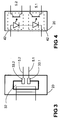
- Fig. 3 is a further embodiment instead of a Current transformer 22 with separate secondary circuits 23.1 and 23.2 a Hall element 32 also with separate secondary circuits 33.1 and 33.2 are shown.
Landscapes
- Engineering & Computer Science (AREA)
- Mechanical Engineering (AREA)
- Train Traffic Observation, Control, And Security (AREA)
- Electric Propulsion And Braking For Vehicles (AREA)
Abstract
Description
- Barrierenantrieb,
- Barrienkontakt,
- Signallampenansteuerung,
- Weichenansteuerung,
- Kontakt der eine Weichenlage repräsentiert.
- Figur 1
- Schaltungsanordnung zur Erzeugung einer Rückmeldung gemäss dem Stand der Technik;
- Figur 2
- erfindungsgemässe Schaltungsanordnung zur Erzeugung einer eisenbahntechnisch sicheren Rückmeldung in einer ersten Ausführungsform mit einem Stromwandler;
- Figur 3
- erfindungsgemässe Schaltungsanordnung in einer zweiten Ausführungsform mit einem Hallelement;
- Figur 4
- erfindungsgemässe Schaltungsanordnung in einer dritten Ausführungsform mit einem elektrooptischen Koppelelement.
- 1
- Kommando
- 2
- Rückmeldung
- 3
- Leitung zwischen erster und zweiter eisenbahntechnischer Einheit, meist im Gleisbereich angeordnet
- 4
- elektromagnetische Störbeeinflussung im Gleisbereich
- 5
- Kommando an eine weitere Eisenbahntechnische Einheit 30
- 5.1, 5.2
- getrennte Leitungen zur Übermittlung eines Kommandos 5
- 10
- erste eisenbahntechnische Einheit, z.B. Anschaltlogik, Stellteil
- 11
- Gleichstromquelle
- 12
- astabiler Multivibrator
- 13
- Stromrelais
- 14
- Ladewiderstand
- 18
- durch ein Kommando 1 schaltbarer Kontakt
- 19
- Gleichspannungsquelle
- 20
- zweite eisenbahntechnische Einheit
- 21
- Innenwiderstand der zweiten eisenbahntechnischen Einheit aus Sicht der Leitung 3 im Ersatzschaltbild
- 22
- Stromwandler
- 23.1, 23.2
- erster und zweiter unabhängiger Sekundärkreis des Stromwandlers 22
- 30
- weitere eisenbahntechnische Einheit, z.B. Balise, Zub, Indusi
- 32
- Hallelement
- 33.1, 33.2
- erster und zweiter unabhängiger Sekundärkreis des Hallelementes 32
- 42
- elektrooptisches Koppelelement
- ist
- Steuerwechselstrom auf der Leitung 3
- Ri
- Innenwiderstandswert
- U1, U1b
- Spannung am Ausgang der ersten eisenbahntechnischen Einheit
- U1a
- Wechselspannung über dem astabilen Multivibrator 12
- U2
- Spannung am Eingang der zweiten eisenbahntechnischen Einheit
Claims (10)
- Verfahren zur Erzeugung einer eisenbahntechnisch sicheren Rückmeldung (2) eines ausgeführten Kommandos (1), wobei das Kommando (1) einer ersten eisenbahntechnischen Einheit (10) zugeführt und über eine Leitung (3) einer zweiten eisenbahntechnischen Einheit (20) zur Ausführung übertragen wird und die Rückmeldung (2) an der ersten eisenbahntechnischen Einheit (10) abgreifbar ist;
gekennzeichnet durch die VerfahrensschritteA die Übertragung des Kommandos (1) erfolgt über eine zweidrahtige Leitung mittels einer in der ersten eisenbahntechnischen Einheit (10) enthaltenen Wechselstromquelle (11, 12);B die Rückmeldung (2) wird aus dem zwischen der ersten und zweiten eisenbahntechnischen Einheit fliessenden Strom (ist) erzeugt. - Verfahren nach Anspruch 1;
dadurch gekennzeichnet, dass
im Verfahrensschritt B die Rückmeldung (2) durch ein in der ersten eisenbahntechnischen Einheit (10) angeordnetes Wechselstromrelais (13) geschaltet wird. - Verfahren nach Anspruch 1 oder 2;
dadurch gekennzeichnet, dass
im Verfahrensschritt A die Wechselstromquelle (11, 12) aus einer mit einem astabilen Multivibrator (12) gekoppelten Gleichstromquelle (11) gebildet wird. - Verfahren nach einem der Ansprüche 1 bis 3,
dadurch gekennzeichnet, dass
die zweite eisenbahntechnische Einheit (20) einen Stromwandler (22) aufweist, an dessen Ausgang ein weiteres Kommando (5) für eine weitere eisenbahntechnische Einheit (30) generiert wird. - Verfahren nach Anspruch 4,
dadurch gekennzeichnet, dass
der Stromwandler (22) zwei unabhängige Sekundärkreise (23.1, 23.2) aufweist. - Verfahren nach einem der Ansprüche 1 bis 3,
dadurch gekennzeichnet, dass
die zweite eisenbahntechnische Einheit (20) ein Hallelement (32) aufweist, an dessen Ausgang (32.1, 33.2) ein weiteres Kommando (5) für eine weitere eisenbahntechnische Einheit (30) generiert wird. - Verfahren nach Anspruch 6,
dadurch gekennzeichnet, dass
das Hallelement (32) zwei unabhängige Sekundärkreise (33.1, 33.2) aufweist. - Verfahren nach einem der Ansprüche 1 bis 3,
dadurch gekennzeichnet, dass
die zweite eisenbahntechnische Einheit (20) ein elektrooptisches Koppelelement (42) aufweist, an dessen Ausgang (5.1, 5.2) ein weiteres Kommando (5) für eine weitere eisenbahntechnische Einheit (30) generiert wird. - Verfahren nach Anspruch 8,
dadurch gekennzeichnet, dass
das zwei unabhängige elektrooptisches Koppelelemente (42) vorgesehen sind. - Schaltungsanordnung zur Durchführung des Verfahrens gemäss einem der Ansprüche 1 bis 9.
Priority Applications (1)
| Application Number | Priority Date | Filing Date | Title |
|---|---|---|---|
| EP20040022257 EP1524167B1 (de) | 2003-10-14 | 2004-09-18 | Verfahren und Schaltungsanordnung zur Erzeugung einer eisenbahntechnisch sicheren Rückmeldung |
Applications Claiming Priority (3)
| Application Number | Priority Date | Filing Date | Title |
|---|---|---|---|
| EP03023063 | 2003-10-14 | ||
| EP03023063 | 2003-10-14 | ||
| EP20040022257 EP1524167B1 (de) | 2003-10-14 | 2004-09-18 | Verfahren und Schaltungsanordnung zur Erzeugung einer eisenbahntechnisch sicheren Rückmeldung |
Publications (3)
| Publication Number | Publication Date |
|---|---|
| EP1524167A2 true EP1524167A2 (de) | 2005-04-20 |
| EP1524167A3 EP1524167A3 (de) | 2009-04-15 |
| EP1524167B1 EP1524167B1 (de) | 2010-11-03 |
Family
ID=34379367
Family Applications (1)
| Application Number | Title | Priority Date | Filing Date |
|---|---|---|---|
| EP20040022257 Expired - Lifetime EP1524167B1 (de) | 2003-10-14 | 2004-09-18 | Verfahren und Schaltungsanordnung zur Erzeugung einer eisenbahntechnisch sicheren Rückmeldung |
Country Status (1)
| Country | Link |
|---|---|
| EP (1) | EP1524167B1 (de) |
Cited By (2)
| Publication number | Priority date | Publication date | Assignee | Title |
|---|---|---|---|---|
| EP1953063A1 (de) * | 2007-02-05 | 2008-08-06 | Alstom Ferroviaria S.P.A. | Ausgabegerät und System zur Verbindung einer Steuerungslogik-Einheit mit einer oder mehreren streckenseitigen Einheiten |
| EP3643579A1 (de) * | 2018-10-23 | 2020-04-29 | Thales Rail Signalling Solutions AG | Vorrichtung und verfahren zur überwachung einer weiche |
Family Cites Families (10)
| Publication number | Priority date | Publication date | Assignee | Title |
|---|---|---|---|---|
| DE1907057C3 (de) * | 1969-02-12 | 1981-09-24 | Standard Elektrik Lorenz Ag, 7000 Stuttgart | Schaltungsanordnung zum Überwachen einer durch einen Blinkgeber getasteten, wechselstromgespeisten Signallampenstromkreises für Eisenbahnsicherungsanlagen |
| DE3140559A1 (de) * | 1981-10-13 | 1983-04-28 | Standard Elektrik Lorenz Ag, 7000 Stuttgart | Schaltungsanordnung zum signaltechnisch sicheren betrieb von signallampen |
| DE3338490A1 (de) * | 1983-10-22 | 1985-05-02 | Standard Elektrik Lorenz Ag, 7000 Stuttgart | Schaltungsanordnung zur ueberwachung des betriebszustandes von in der aussenanlage eines stellwerks eingesetzten wechselstromverbrauchern |
| DE3527828A1 (de) * | 1985-08-02 | 1987-03-26 | Standard Elektrik Lorenz Ag | Einrichtung zur ueberwachung des betriebs einer signallampe |
| US4779071A (en) * | 1985-12-20 | 1988-10-18 | Pianelli and Traveisa S.A.S. | System for transmitting commands |
| DE3715478A1 (de) * | 1987-05-06 | 1988-11-17 | Licentia Gmbh | Schaltungsanordnung zur ueberwachung einer weiche |
| DE3920430A1 (de) * | 1989-06-22 | 1991-01-03 | Standard Elektrik Lorenz Ag | Schaltungsanordnung zur ueberwachung von wechselstromverbrauchern in eisenbahnsignalanlagen |
| DE4132389A1 (de) * | 1991-09-26 | 1993-04-01 | Siemens Ag | Schaltung zum steuern und ueberwachen von lichtsignalen |
| IT1276423B1 (it) * | 1995-06-20 | 1997-10-31 | Ansaldo Trasporti Spa | Sistema di controllo per dispositivi di segnalazione luminosa di tipo ferroviario |
| EP0960797B1 (de) * | 1998-05-25 | 2006-03-15 | Siemens Schweiz AG (Siemens Suisse SA) (Siemens Svizzera SA) Siemens Switzerland Ltd) | Übertragungssystem insbesondere für verkehrstechnische Systeme |
-
2004
- 2004-09-18 EP EP20040022257 patent/EP1524167B1/de not_active Expired - Lifetime
Cited By (2)
| Publication number | Priority date | Publication date | Assignee | Title |
|---|---|---|---|---|
| EP1953063A1 (de) * | 2007-02-05 | 2008-08-06 | Alstom Ferroviaria S.P.A. | Ausgabegerät und System zur Verbindung einer Steuerungslogik-Einheit mit einer oder mehreren streckenseitigen Einheiten |
| EP3643579A1 (de) * | 2018-10-23 | 2020-04-29 | Thales Rail Signalling Solutions AG | Vorrichtung und verfahren zur überwachung einer weiche |
Also Published As
| Publication number | Publication date |
|---|---|
| EP1524167B1 (de) | 2010-11-03 |
| EP1524167A3 (de) | 2009-04-15 |
Similar Documents
| Publication | Publication Date | Title |
|---|---|---|
| EP0071873A2 (de) | Schaltungsanordnung zum Wahrnehmen von Gegenständen mit einer Leiterschleife | |
| DE944735C (de) | Schaltungsanordnung fuer Fernsprechanlagen mit Haupt- und Unteraemtern sowie Sammelleitungen | |
| EP2868548B1 (de) | Verfahren zur Überwachung eines Schaltungszustandes eines Schalters eines Zugsicherungssystem, sowie Zugsicherungssystem | |
| DE102013107968A1 (de) | Online-Überwachungssystem für den Einsatz in elektrischen Anlagen und Verfahren zu dessen Betrieb | |
| EP3639365B1 (de) | Einfehlersichere isolationswiderstandsbestimmung in einer photovoltaikanlage | |
| DE19709840C2 (de) | Einrichtung für die Achszählung zum Unterscheiden von Radbeeinflussungen und Nicht-Radbeeinflussungen | |
| CH650619A5 (de) | Anordnung zur betriebsspannungsversorgung einer fehlerstrom-schutzschaltungsanordnung. | |
| DE202007019127U1 (de) | Vorrichtung zur Messung eines von einem Wechselstromanteil überlagerten Gleichstromanteils eines in Leitern von Wechselstrombahnen fließenden Stroms | |
| EP1524167A2 (de) | Verfahren und Schaltungsanordnung zur Erzeugung einer eisenbahntechnisch sicheren Rückmeldung | |
| DE2731453A1 (de) | Erdschlussdetektor | |
| DE19510519A1 (de) | Anordnung sowie Schaltungsanordnung zur Diagnose, Überwachung und/oder Steuerung von Energiewandlungssystemen | |
| CH698721B1 (de) | Verfahren und Schaltungsanordnung zum Übertragen eines zweiwertigen Signals. | |
| DE2842966C2 (de) | Schaltung zur Überwachung der Steuerausgänge einer weiteren Schaltung | |
| DE2335280C2 (de) | Fahrzeugbetätigte Einrichtung | |
| DE102004023723B3 (de) | Erzeugen eines Signals an einer Strecke für Schienenfahrzeuge | |
| DE112018007853T5 (de) | Schienenbruch-erkennungsvorrichtung und schienenbruchresultat-managementsystem | |
| DE102005054544B4 (de) | Verfahren und Einrichtung zur Ortung von Isolationsfehlern in isolierten ungeerdeten Wechselspannungsnetzen | |
| DE19729464C1 (de) | Schaltungsanordnung für eine Ausgangsstufe | |
| DE231932C (de) | ||
| DE234021C (de) | ||
| DE102017123815A1 (de) | Wechselrichter und verfahren zum betrieb eines wechselrichters | |
| DE269797C (de) | ||
| DE102016217470B4 (de) | Anordnung zur Erfassung und Abschaltung von Fehlerströmen | |
| DE2829282C2 (de) | Einrichtung zum Vergleichen zweier Gleichstromsignale | |
| EP0913904A2 (de) | Verfahren zur Erhöhung der Zuverlässigkeit eines Fehlerstrom-Schutzschalters und Fehlerstrom-Schutzschalter zur Durchführung dieses Verfahrens |
Legal Events
| Date | Code | Title | Description |
|---|---|---|---|
| PUAI | Public reference made under article 153(3) epc to a published international application that has entered the european phase |
Free format text: ORIGINAL CODE: 0009012 |
|
| AK | Designated contracting states |
Kind code of ref document: A2 Designated state(s): AT BE BG CH CY CZ DE DK EE ES FI FR GB GR HU IE IT LI LU MC NL PL PT RO SE SI SK TR |
|
| AX | Request for extension of the european patent |
Extension state: AL HR LT LV MK |
|
| RAP1 | Party data changed (applicant data changed or rights of an application transferred) |
Owner name: SIEMENS SCHWEIZ AG |
|
| PUAL | Search report despatched |
Free format text: ORIGINAL CODE: 0009013 |
|
| AK | Designated contracting states |
Kind code of ref document: A3 Designated state(s): AT BE BG CH CY CZ DE DK EE ES FI FR GB GR HU IE IT LI LU MC NL PL PT RO SE SI SK TR |
|
| AX | Request for extension of the european patent |
Extension state: AL HR LT LV MK |
|
| 17P | Request for examination filed |
Effective date: 20090506 |
|
| 17Q | First examination report despatched |
Effective date: 20090610 |
|
| AKX | Designation fees paid |
Designated state(s): AT BE BG CH CY CZ DE DK EE ES FI FR GB GR HU IE IT LI LU MC NL PL PT RO SE SI SK TR |
|
| GRAP | Despatch of communication of intention to grant a patent |
Free format text: ORIGINAL CODE: EPIDOSNIGR1 |
|
| GRAS | Grant fee paid |
Free format text: ORIGINAL CODE: EPIDOSNIGR3 |
|
| GRAA | (expected) grant |
Free format text: ORIGINAL CODE: 0009210 |
|
| AK | Designated contracting states |
Kind code of ref document: B1 Designated state(s): AT BE BG CH CY CZ DE DK EE ES FI FR GB GR HU IE IT LI LU MC NL PL PT RO SE SI SK TR |
|
| REG | Reference to a national code |
Ref country code: GB Ref legal event code: FG4D Free format text: NOT ENGLISH |
|
| REG | Reference to a national code |
Ref country code: CH Ref legal event code: NV Representative=s name: SIEMENS SCHWEIZ AG Ref country code: CH Ref legal event code: EP |
|
| REG | Reference to a national code |
Ref country code: IE Ref legal event code: FG4D Free format text: LANGUAGE OF EP DOCUMENT: GERMAN |
|
| REF | Corresponds to: |
Ref document number: 502004011846 Country of ref document: DE Date of ref document: 20101216 Kind code of ref document: P |
|
| REG | Reference to a national code |
Ref country code: NL Ref legal event code: VDEP Effective date: 20101103 |
|
| REG | Reference to a national code |
Ref country code: IE Ref legal event code: FD4D |
|
| PG25 | Lapsed in a contracting state [announced via postgrant information from national office to epo] |
Ref country code: NL Free format text: LAPSE BECAUSE OF FAILURE TO SUBMIT A TRANSLATION OF THE DESCRIPTION OR TO PAY THE FEE WITHIN THE PRESCRIBED TIME-LIMIT Effective date: 20101103 Ref country code: FI Free format text: LAPSE BECAUSE OF FAILURE TO SUBMIT A TRANSLATION OF THE DESCRIPTION OR TO PAY THE FEE WITHIN THE PRESCRIBED TIME-LIMIT Effective date: 20101103 Ref country code: SE Free format text: LAPSE BECAUSE OF FAILURE TO SUBMIT A TRANSLATION OF THE DESCRIPTION OR TO PAY THE FEE WITHIN THE PRESCRIBED TIME-LIMIT Effective date: 20101103 Ref country code: SI Free format text: LAPSE BECAUSE OF FAILURE TO SUBMIT A TRANSLATION OF THE DESCRIPTION OR TO PAY THE FEE WITHIN THE PRESCRIBED TIME-LIMIT Effective date: 20101103 Ref country code: BG Free format text: LAPSE BECAUSE OF FAILURE TO SUBMIT A TRANSLATION OF THE DESCRIPTION OR TO PAY THE FEE WITHIN THE PRESCRIBED TIME-LIMIT Effective date: 20110203 Ref country code: PT Free format text: LAPSE BECAUSE OF FAILURE TO SUBMIT A TRANSLATION OF THE DESCRIPTION OR TO PAY THE FEE WITHIN THE PRESCRIBED TIME-LIMIT Effective date: 20110303 |
|
| PG25 | Lapsed in a contracting state [announced via postgrant information from national office to epo] |
Ref country code: GR Free format text: LAPSE BECAUSE OF FAILURE TO SUBMIT A TRANSLATION OF THE DESCRIPTION OR TO PAY THE FEE WITHIN THE PRESCRIBED TIME-LIMIT Effective date: 20110204 |
|
| PG25 | Lapsed in a contracting state [announced via postgrant information from national office to epo] |
Ref country code: ES Free format text: LAPSE BECAUSE OF FAILURE TO SUBMIT A TRANSLATION OF THE DESCRIPTION OR TO PAY THE FEE WITHIN THE PRESCRIBED TIME-LIMIT Effective date: 20110214 Ref country code: CZ Free format text: LAPSE BECAUSE OF FAILURE TO SUBMIT A TRANSLATION OF THE DESCRIPTION OR TO PAY THE FEE WITHIN THE PRESCRIBED TIME-LIMIT Effective date: 20101103 Ref country code: IE Free format text: LAPSE BECAUSE OF FAILURE TO SUBMIT A TRANSLATION OF THE DESCRIPTION OR TO PAY THE FEE WITHIN THE PRESCRIBED TIME-LIMIT Effective date: 20101103 Ref country code: EE Free format text: LAPSE BECAUSE OF FAILURE TO SUBMIT A TRANSLATION OF THE DESCRIPTION OR TO PAY THE FEE WITHIN THE PRESCRIBED TIME-LIMIT Effective date: 20101103 |
|
| PG25 | Lapsed in a contracting state [announced via postgrant information from national office to epo] |
Ref country code: PL Free format text: LAPSE BECAUSE OF FAILURE TO SUBMIT A TRANSLATION OF THE DESCRIPTION OR TO PAY THE FEE WITHIN THE PRESCRIBED TIME-LIMIT Effective date: 20101103 Ref country code: DK Free format text: LAPSE BECAUSE OF FAILURE TO SUBMIT A TRANSLATION OF THE DESCRIPTION OR TO PAY THE FEE WITHIN THE PRESCRIBED TIME-LIMIT Effective date: 20101103 Ref country code: RO Free format text: LAPSE BECAUSE OF FAILURE TO SUBMIT A TRANSLATION OF THE DESCRIPTION OR TO PAY THE FEE WITHIN THE PRESCRIBED TIME-LIMIT Effective date: 20101103 Ref country code: SK Free format text: LAPSE BECAUSE OF FAILURE TO SUBMIT A TRANSLATION OF THE DESCRIPTION OR TO PAY THE FEE WITHIN THE PRESCRIBED TIME-LIMIT Effective date: 20101103 |
|
| PLBE | No opposition filed within time limit |
Free format text: ORIGINAL CODE: 0009261 |
|
| STAA | Information on the status of an ep patent application or granted ep patent |
Free format text: STATUS: NO OPPOSITION FILED WITHIN TIME LIMIT |
|
| 26N | No opposition filed |
Effective date: 20110804 |
|
| REG | Reference to a national code |
Ref country code: DE Ref legal event code: R097 Ref document number: 502004011846 Country of ref document: DE Effective date: 20110804 |
|
| PG25 | Lapsed in a contracting state [announced via postgrant information from national office to epo] |
Ref country code: IT Free format text: LAPSE BECAUSE OF FAILURE TO SUBMIT A TRANSLATION OF THE DESCRIPTION OR TO PAY THE FEE WITHIN THE PRESCRIBED TIME-LIMIT Effective date: 20101103 |
|
| BERE | Be: lapsed |
Owner name: SIEMENS SCHWEIZ A.G. Effective date: 20110930 |
|
| PG25 | Lapsed in a contracting state [announced via postgrant information from national office to epo] |
Ref country code: MC Free format text: LAPSE BECAUSE OF NON-PAYMENT OF DUE FEES Effective date: 20110930 |
|
| GBPC | Gb: european patent ceased through non-payment of renewal fee |
Effective date: 20110918 |
|
| REG | Reference to a national code |
Ref country code: FR Ref legal event code: ST Effective date: 20120531 |
|
| PG25 | Lapsed in a contracting state [announced via postgrant information from national office to epo] |
Ref country code: BE Free format text: LAPSE BECAUSE OF NON-PAYMENT OF DUE FEES Effective date: 20110930 |
|
| PG25 | Lapsed in a contracting state [announced via postgrant information from national office to epo] |
Ref country code: FR Free format text: LAPSE BECAUSE OF NON-PAYMENT OF DUE FEES Effective date: 20110930 Ref country code: GB Free format text: LAPSE BECAUSE OF NON-PAYMENT OF DUE FEES Effective date: 20110918 |
|
| PGFP | Annual fee paid to national office [announced via postgrant information from national office to epo] |
Ref country code: DE Payment date: 20121119 Year of fee payment: 9 Ref country code: CH Payment date: 20121210 Year of fee payment: 9 |
|
| PG25 | Lapsed in a contracting state [announced via postgrant information from national office to epo] |
Ref country code: CY Free format text: LAPSE BECAUSE OF EXPIRATION OF PROTECTION Effective date: 20101103 Ref country code: LU Free format text: LAPSE BECAUSE OF NON-PAYMENT OF DUE FEES Effective date: 20110918 |
|
| PG25 | Lapsed in a contracting state [announced via postgrant information from national office to epo] |
Ref country code: TR Free format text: LAPSE BECAUSE OF FAILURE TO SUBMIT A TRANSLATION OF THE DESCRIPTION OR TO PAY THE FEE WITHIN THE PRESCRIBED TIME-LIMIT Effective date: 20101103 |
|
| PG25 | Lapsed in a contracting state [announced via postgrant information from national office to epo] |
Ref country code: HU Free format text: LAPSE BECAUSE OF FAILURE TO SUBMIT A TRANSLATION OF THE DESCRIPTION OR TO PAY THE FEE WITHIN THE PRESCRIBED TIME-LIMIT Effective date: 20101103 |
|
| PGFP | Annual fee paid to national office [announced via postgrant information from national office to epo] |
Ref country code: AT Payment date: 20130911 Year of fee payment: 10 |
|
| REG | Reference to a national code |
Ref country code: CH Ref legal event code: PL |
|
| REG | Reference to a national code |
Ref country code: AT Ref legal event code: MM01 Ref document number: 486759 Country of ref document: AT Kind code of ref document: T Effective date: 20130918 |
|
| REG | Reference to a national code |
Ref country code: DE Ref legal event code: R119 Ref document number: 502004011846 Country of ref document: DE Effective date: 20140401 |
|
| PG25 | Lapsed in a contracting state [announced via postgrant information from national office to epo] |
Ref country code: LI Free format text: LAPSE BECAUSE OF NON-PAYMENT OF DUE FEES Effective date: 20130930 Ref country code: CH Free format text: LAPSE BECAUSE OF NON-PAYMENT OF DUE FEES Effective date: 20130930 |
|
| PG25 | Lapsed in a contracting state [announced via postgrant information from national office to epo] |
Ref country code: DE Free format text: LAPSE BECAUSE OF NON-PAYMENT OF DUE FEES Effective date: 20140401 |
|
| PG25 | Lapsed in a contracting state [announced via postgrant information from national office to epo] |
Ref country code: AT Free format text: THE PATENT HAS BEEN ANNULLED BY A DECISION OF A NATIONAL AUTHORITY Effective date: 20130918 |