EP1524068A1 - Werkzeugmaschine mit schwenkbarem Werkstückträger, dessen Torsions-Moment kompensiert ist - Google Patents
Werkzeugmaschine mit schwenkbarem Werkstückträger, dessen Torsions-Moment kompensiert ist Download PDFInfo
- Publication number
- EP1524068A1 EP1524068A1 EP03023017A EP03023017A EP1524068A1 EP 1524068 A1 EP1524068 A1 EP 1524068A1 EP 03023017 A EP03023017 A EP 03023017A EP 03023017 A EP03023017 A EP 03023017A EP 1524068 A1 EP1524068 A1 EP 1524068A1
- Authority
- EP
- European Patent Office
- Prior art keywords
- pivot
- machine tool
- carrier
- force
- tool according
- Prior art date
- Legal status (The legal status is an assumption and is not a legal conclusion. Google has not performed a legal analysis and makes no representation as to the accuracy of the status listed.)
- Granted
Links
- 230000005484 gravity Effects 0.000 claims abstract description 10
- 238000004146 energy storage Methods 0.000 claims description 10
- 230000003068 static effect Effects 0.000 description 8
- 239000012530 fluid Substances 0.000 description 4
- 239000000969 carrier Substances 0.000 description 3
- 238000003754 machining Methods 0.000 description 3
- 230000006835 compression Effects 0.000 description 1
- 238000007906 compression Methods 0.000 description 1
- 239000007788 liquid Substances 0.000 description 1
Images


Classifications
-
- B—PERFORMING OPERATIONS; TRANSPORTING
- B23—MACHINE TOOLS; METAL-WORKING NOT OTHERWISE PROVIDED FOR
- B23Q—DETAILS, COMPONENTS, OR ACCESSORIES FOR MACHINE TOOLS, e.g. ARRANGEMENTS FOR COPYING OR CONTROLLING; MACHINE TOOLS IN GENERAL CHARACTERISED BY THE CONSTRUCTION OF PARTICULAR DETAILS OR COMPONENTS; COMBINATIONS OR ASSOCIATIONS OF METAL-WORKING MACHINES, NOT DIRECTED TO A PARTICULAR RESULT
- B23Q11/00—Accessories fitted to machine tools for keeping tools or parts of the machine in good working condition or for cooling work; Safety devices specially combined with or arranged in, or specially adapted for use in connection with, machine tools
- B23Q11/001—Arrangements compensating weight or flexion on parts of the machine
- B23Q11/0017—Arrangements compensating weight or flexion on parts of the machine compensating the weight of vertically moving elements, e.g. by balancing liftable machine parts
- B23Q11/0021—Arrangements compensating weight or flexion on parts of the machine compensating the weight of vertically moving elements, e.g. by balancing liftable machine parts the elements being rotating or pivoting
-
- B—PERFORMING OPERATIONS; TRANSPORTING
- B23—MACHINE TOOLS; METAL-WORKING NOT OTHERWISE PROVIDED FOR
- B23Q—DETAILS, COMPONENTS, OR ACCESSORIES FOR MACHINE TOOLS, e.g. ARRANGEMENTS FOR COPYING OR CONTROLLING; MACHINE TOOLS IN GENERAL CHARACTERISED BY THE CONSTRUCTION OF PARTICULAR DETAILS OR COMPONENTS; COMBINATIONS OR ASSOCIATIONS OF METAL-WORKING MACHINES, NOT DIRECTED TO A PARTICULAR RESULT
- B23Q1/00—Members which are comprised in the general build-up of a form of machine, particularly relatively large fixed members
- B23Q1/25—Movable or adjustable work or tool supports
- B23Q1/44—Movable or adjustable work or tool supports using particular mechanisms
- B23Q1/50—Movable or adjustable work or tool supports using particular mechanisms with rotating pairs only, the rotating pairs being the first two elements of the mechanism
- B23Q1/54—Movable or adjustable work or tool supports using particular mechanisms with rotating pairs only, the rotating pairs being the first two elements of the mechanism two rotating pairs only
- B23Q1/5406—Movable or adjustable work or tool supports using particular mechanisms with rotating pairs only, the rotating pairs being the first two elements of the mechanism two rotating pairs only a single rotating pair followed perpendicularly by a single rotating pair
-
- B—PERFORMING OPERATIONS; TRANSPORTING
- B23—MACHINE TOOLS; METAL-WORKING NOT OTHERWISE PROVIDED FOR
- B23Q—DETAILS, COMPONENTS, OR ACCESSORIES FOR MACHINE TOOLS, e.g. ARRANGEMENTS FOR COPYING OR CONTROLLING; MACHINE TOOLS IN GENERAL CHARACTERISED BY THE CONSTRUCTION OF PARTICULAR DETAILS OR COMPONENTS; COMBINATIONS OR ASSOCIATIONS OF METAL-WORKING MACHINES, NOT DIRECTED TO A PARTICULAR RESULT
- B23Q11/00—Accessories fitted to machine tools for keeping tools or parts of the machine in good working condition or for cooling work; Safety devices specially combined with or arranged in, or specially adapted for use in connection with, machine tools
- B23Q11/001—Arrangements compensating weight or flexion on parts of the machine
- B23Q11/0017—Arrangements compensating weight or flexion on parts of the machine compensating the weight of vertically moving elements, e.g. by balancing liftable machine parts
- B23Q11/0025—Arrangements compensating weight or flexion on parts of the machine compensating the weight of vertically moving elements, e.g. by balancing liftable machine parts using resilient means, e.g. springs, hydraulic dampers
-
- B—PERFORMING OPERATIONS; TRANSPORTING
- B23—MACHINE TOOLS; METAL-WORKING NOT OTHERWISE PROVIDED FOR
- B23Q—DETAILS, COMPONENTS, OR ACCESSORIES FOR MACHINE TOOLS, e.g. ARRANGEMENTS FOR COPYING OR CONTROLLING; MACHINE TOOLS IN GENERAL CHARACTERISED BY THE CONSTRUCTION OF PARTICULAR DETAILS OR COMPONENTS; COMBINATIONS OR ASSOCIATIONS OF METAL-WORKING MACHINES, NOT DIRECTED TO A PARTICULAR RESULT
- B23Q39/00—Metal-working machines incorporating a plurality of sub-assemblies, each capable of performing a metal-working operation
- B23Q2039/002—Machines with twin spindles
Definitions
- the invention relates to a machine tool according to the preamble of Claim 1.
- the invention is based on the object, a machine tool of generic type in such a way that the torsion moment with sufficiently simple means is compensated sufficiently.
- the core of the invention is that at least an energy store with an approximately constant force over its path acting as a crank mechanism on the pivot carrier, so that a substantially Sinusoidal compensation torque is generated, which is the sinusoidal Torsion moment is directed opposite, creating a extensive compensation of the torsional moment is achieved. Went out This assumes that the swivel drive is on one side of the Swivel-carrier attacks. Attacks only on the swivel drive opposite End of the pivot-carrier compensation device on, with a complete or approximately complete compensation of the static torsion moment, there is no reduction the torsion and therefore the twisting, but minimizing the static Load of the drive instead.
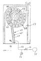
- the machine tool shown in the drawing is around a double spindle machine tool with a rectangular, through a frame formed stator 1, by extending in the y-direction vertical side supports 2, 3 and each one connecting them horizontal, extending in the x direction upper cross-beam 4 and a lower, not shown transverse spar is formed.
- the side supports 2, 3 and the transverse bars 4 enclose an inner space 5, the is open on both sides, in particular to the working space 6 out.
- Of the Stand 1 is supported by a base 7 on a foundation plate 8.
- each transverse bars 4 each have an x-guide rail 10 mounted on which the x-carriage 9 is guided.
- the drive of the x-carriage 9 by means of an x-motor 11 via a extending in the x-direction, in the side supports 2, 3 of the stator. 1 rotatably mounted x ball screw 12.
- On the working space 7 facing end side of the x-carriage 9 is a in y-direction, that is vertically displaceable y-slide 13 out.
- On the side areas and a vertical central web 14 of the frame-like x-slide 9 each have a y-guide rail 15 attached, on which the y-carriage 13 is slidably guided.
- the drive of the y-carriage 13 is effected by means of a mounted on the x-carriage 9 y motor 16 via a y-ball screw 17.
- the tool spindles 18, 19 are each extending about in the z-direction Z-rotation axis 21, 22 by means of a drive motor, not shown drivable.
- the tool spindles 18, 19 are relative in the x and y directions fixed to each other on the y-carriage, but in the z-direction slidably disposed on z-guide rails 23.
- a Workpiece support bed 24 mounted on which a workpiece carrier 25 is supported is.
- the workpiece carrier 25 is designed in the manner of a bridge, the side cheeks 26 supported on the workpiece carrier bed 24, 27, in which a pivot support 28 extends about an x-direction Swivel axis 29 is pivotally mounted.
- the swivel drive takes place by means of a pivoting motor 30.
- two y-turntables 31, 32 are arranged, each by means of a mounted in the pivot carrier 28 y-rotation motor 33, 34 about a vertical, ie in the y-direction, y-axis of rotation 35, 36 are rotationally driven.
- On the y-turntables 31, 32 is in each case a workpiece carrier 37, 38 attached, the one to be machined Can pick up workpiece.
- Simultaneous machining of fundamentally identical workpieces by means recorded in the spindles 18, 19 tools takes place in the Way that identical movements of the tool spindles 18, 19 in x and y-direction by means of the x-carriage 9 and the y-carriage 13 executed become.
- the usually identical movements of the Tools in the z-direction are displaced by means of the z-direction Tool spindles 18, 19 executed.
- the center of gravity 39 of the pivot carrier 28 including y-turntables 31, 32 and workpiece carriers 37, 38 below the pivot axis 29.
- Center of gravity 39 shifts Center of gravity 39 relative to the pivot axis 29; He remains in each one conceivable application on the workpiece carriers 37, 38 facing away Side of the pivot axis 29.
- a compensation device 40th which exerts a substantially constant force in each position.
- These Compensation device 40 engages on a pivot carrier 28th attached lever arm 41, which is parallel to the position of the center of gravity 39th to the pivot axis 39 extends. This lever arm 41 then runs, when the center of gravity 39 is perpendicular below the pivot axis 29 is located vertically downwards.
- the compensation device 40 may be as shown in Fig. 1 to 3 designed as a gas spring energy storage 42 act its filled with compressed gas cylinder 43 in the lower area the side cheek 27 is articulated by means of a pivot joint 44. His Piston rod 45 is also by means of a pivot joint 46 on Lever arm 41 hinged. Such gas springs are regularly dimensioned that the ejection force over the Ausschubweg the piston rod 45 changes only slightly.
- the lever arm 41 has several force-attack points 47 at different distances a from the pivot axis 29 on which the pivoting joint 46 can be attached, so that the force-attack point 47 corresponding to the weight and the Shape of workpieces to be machined to produce different Compensation torques can be selected.
- a towing device 50 for the supply lines 48 provided on the compensation device 40 associated side is arranged.
- this towing device 52 follow the pivoting movements of the pivoting carrier 28.
- a collision the energy accumulator 42 with the towing device 52 does not take place, as long as the pivoting movement of the pivot carrier 28 only one
- Each angle about 135 ° to either side of the already mentioned vertical connecting line between the lower pivot joint 44 and the pivot axis 29 takes place.
- a free spin of the Compensation device 40 is not possible here, but not necessary. In this embodiment engages at both ends of the pivot carrier 28 each an identical compensation device 40 at.
- the energy storage 42 ' can also be shown in FIG. 5 as with pressure medium be acted upon piston-cylinder drive, its cylinder 43 'to a pressure compensating memory 51 via a connection line 52 is connected.
- a pressure medium either Compressed gas or hydraulic fluid or both can be used.
- a filling line 53 in which a Shut-off valve 54 is located.
- a compressed gas filling 55 in the form of a gas bubble.
- a pressurized liquid filling 56 is supplied until in Pressure equalization memory 51 a predetermined pressure prevails.
- the Hydraulic fluid filling 56 is constantly connected to the cylinder 43 ', prevails in the whole system of energy storage 42 'and pressure compensation memory 51 the same pressure. Because the volume of pressure compensation memory 51 and in particular the volume of compressed gas filling 55 in the state biased to operating pressure is large the volume around which the system mentioned when extending or retracting the piston rod 45 in the cylinder 43 'changed, occur only minor Pressure changes in the system. In such an embodiment Thus, the prevailing in the cylinder 43 'pressure and thus the of the piston rod 45 exerted force over the full Ausschubweg the Piston rod 45 are held almost exactly constant.
- the pressure in the Pressure compensation memory 51 is by means of a pressure gauge 57th detected.
- the force memory 42 'can also via a connection line 52 directly to an only indicated operational compressed air supply system 58 are connected, wherein in line 52 again, a shut-off valve 54, which is a pressure-measuring device 57 is downstream, so that the pressure in the power storage 42 'to a Basic value can be set.
- a shut-off valve 54 which is a pressure-measuring device 57 is downstream, so that the pressure in the power storage 42 'to a Basic value can be set.
Landscapes
- Engineering & Computer Science (AREA)
- Mechanical Engineering (AREA)
- Machine Tool Units (AREA)
Abstract
Description
- Fig. 1
- eine Stimansicht einer Werkzeugmaschine nach der Erfin-dung,
- Fig. 2
- eine Teil-Seitenansicht entsprechend dem Sichtpfeil II in Fig. 1 mit einer Kompensations-Einrichtung in einer unverschwenkten Stellung eines Schwenk-Trägers,
- Fig. 3
- die Ansicht gemäß Fig. 2 in einer verschwenkten Position der Kompensations-Einrichtung,
- Fig. 4
- eine Stirn-Ansicht einer abgewandelten Ausführungsform eines Schwenk-Trägers,
- Fig. 5
- eine Teil-Seitenansicht gemäß dem Sichtpfeil V in Fig. 4 in einer Fig. 2 entsprechenden Stellung und
- Fig. 6
- eine Ansicht gemäß Fig. 5 in einer Fig. 3 entsprechenden Position.
Claims (10)
- Werkzeugmaschinedadurch gekennzeichnet, dass mindestens im Bereich des ersten oder des zweiten Endes des Schwenk-Trägers (28) ein Kraftspeicher (42, 42') im Abstand (a) von der Schwenk-Achse (29) an einer Kraft-Angriffs-Stelle (47) des Schwenk-Trägers (28) angreift, der ein dem Torsions-Moment entgegengerichtetes Kompensations-Moment auf den Schwenk-Träger (28) ausübt.mit einem Schwenk-Träger (28),auf dem mindestens ein Werkstück-Träger (37, 38) angeordnet ist,der ein erstes Ende und ein zweites Ende aufweist,der an seinem ersten Ende und an seinem zweiten Ende um eine Schwenk-Achse (29) schwenkbar gelagert ist,dessen Schwerpunkt (39) unter Erzeugung eines auf den Schwenk-Träger (28) wirkenden Torsions-Momentes außerhalb der Schwenk-Achse (29) liegt,mit einem im Bereich des ersten Endes des Schwenk-Trägers (28) angreifenden Schwenk-Motor (30) undmit mindestens einer Werkzeug-Spindel (18, 19), die relativ zum Werkstück-Träger (37, 38) bewegbar ist,
- Werkzeugmaschine nach Anspruch 1, dadurch gekennzeichnet, dass sowohl am ersten als auch am zweiten Ende des Schwenk-Trägers (28) ein Kraftspeicher (42') im Abstand (a) von der Schwenk-Achse (29) an einer Kraft-Angriffs-Stelle (47) des Schwenk-Trägers (28) angreift.
- Werkzeugmaschine nach Anspruch 1, dadurch gekennzeichnet, dass der Kraftspeicher (42) als Gasfeder ausgebildet ist.
- Werkzeugmaschine nach Anspruch 1, dadurch gekennzeichnet, dass der Kraftspeicher (42') als Kolben-Zylinder-Einheit ausgebildet ist, dessen Zylinder (43') mit einem Druck-Ausgleichs-Speicher (51) verbunden ist.
- Werkzeugmaschine nach Anspruch 1, dadurch gekennzeichnet, dass der Kraftspeicher (42') als Kolben-Zylinder-Einheit ausgebildet ist, dessen Zylinder (43') mit einem sonstigen Druck-Versorgungs-System (58) verbindbar ist.
- Werkzeugmaschine nach einem der Ansprüche 3 bis 5, dadurch gekennzeichnet, dass ein Grundwert des Druckes im Kraftspeicher (42) einstellbar ist.
- Werkzeugmaschine nach Anspruch 1, dadurch gekennzeichnet, dass der Kraftspeicher (42, 42') mit einem der Kraft-Angriffs-Stelle (47) entgegengesetzten Ende mittels eines Schwenk-Gelenks (46) ortsfest angelenkt ist.
- Werkzeugmaschine nach Anspruch 7, dadurch gekennzeichnet, dass für das Verhältnis des Abstands (b) des Schwenk-Gelenks (46) von der Schwenk-Achse (29) zum Abstand (a) der Kraft-Angriffs-Stelle (47) von der Schwenk-Achse (29) gilt: b/a ≥3,0.
- Werkzeugmaschine nach Anspruch 1, dadurch gekennzeichnet, dass der Abstand (a) der Kraft-Angriffs-Stelle (47) von der Schwenk-Achse (29) veränderbar ist.
- Werkzeugmaschine nach Anspruch 9, dadurch gekennzeichnet, dass der Schwenk-Träger (28) mehrere Kraft-Angriffs-Stellen (47) unterschiedlichen Abstands (a) zur Schwenk-Achse (29) aufweist, an denen der Kraftspeicher (42, 42') mit dem Schwenk-Träger (28) verbindbar ist.
Priority Applications (3)
| Application Number | Priority Date | Filing Date | Title |
|---|---|---|---|
| DE50309792T DE50309792D1 (de) | 2003-10-13 | 2003-10-13 | Werkzeugmaschine mit schwenkbarem Werkstückträger, dessen Torsions-Moment kompensiert ist |
| EP20030023017 EP1524068B1 (de) | 2003-10-13 | 2003-10-13 | Werkzeugmaschine mit schwenkbarem Werkstückträger, dessen Torsions-Moment kompensiert ist |
| ES03023017T ES2305380T3 (es) | 2003-10-13 | 2003-10-13 | Maquina herramienta con portapiezas basculante cuyo par de torsion esta compensado. |
Applications Claiming Priority (1)
| Application Number | Priority Date | Filing Date | Title |
|---|---|---|---|
| EP20030023017 EP1524068B1 (de) | 2003-10-13 | 2003-10-13 | Werkzeugmaschine mit schwenkbarem Werkstückträger, dessen Torsions-Moment kompensiert ist |
Publications (2)
| Publication Number | Publication Date |
|---|---|
| EP1524068A1 true EP1524068A1 (de) | 2005-04-20 |
| EP1524068B1 EP1524068B1 (de) | 2008-05-07 |
Family
ID=34354434
Family Applications (1)
| Application Number | Title | Priority Date | Filing Date |
|---|---|---|---|
| EP20030023017 Expired - Lifetime EP1524068B1 (de) | 2003-10-13 | 2003-10-13 | Werkzeugmaschine mit schwenkbarem Werkstückträger, dessen Torsions-Moment kompensiert ist |
Country Status (3)
| Country | Link |
|---|---|
| EP (1) | EP1524068B1 (de) |
| DE (1) | DE50309792D1 (de) |
| ES (1) | ES2305380T3 (de) |
Cited By (4)
| Publication number | Priority date | Publication date | Assignee | Title |
|---|---|---|---|---|
| EP1693147A1 (de) * | 2005-02-16 | 2006-08-23 | Cross Hüller GmbH | Doppelspindel-Werkzeugmaschine mit zwei Werkstückhaltern von denen einer verstellbar ist |
| US7544025B2 (en) | 2005-02-16 | 2009-06-09 | Cross Hüller GmbH | Double-spindle machine tool |
| US20130216323A1 (en) * | 2010-08-27 | 2013-08-22 | Datron Ag | Machine tool |
| DE202017107553U1 (de) | 2017-12-12 | 2019-03-13 | Starrag Gmbh | Werkzeugmaschine mit einer das Werkstück aufnehmenden Schwenkbrücke |
Families Citing this family (3)
| Publication number | Priority date | Publication date | Assignee | Title |
|---|---|---|---|---|
| DE102009057423A1 (de) | 2009-12-08 | 2011-06-09 | Robert Bosch Gmbh | Werkzeugmaschine mit hydraulisch stabilisiertem Schwenkträger |
| DE202017101766U1 (de) | 2017-03-28 | 2018-06-29 | Starrag Gmbh | Werkzeugmaschine mit einer Schwenkbrücke |
| DE102017106569B4 (de) | 2017-03-28 | 2019-01-24 | Starrag Gmbh | Werkzeugmaschine mit einer Schwenkbrücke |
Citations (3)
| Publication number | Priority date | Publication date | Assignee | Title |
|---|---|---|---|---|
| DE19745233A1 (de) * | 1996-10-19 | 1998-04-23 | Horkos Corp | Spindel-Halterungskasten für Werkzeugmaschinen, Dämpfungseinrichtung für Werkzeugmaschinen, Gaszuführeinrichtungen für Werkzeugmaschinen und gasbetätigte Einrichtung mit Ausgleichszylinder für Werkzeugmaschinen |
| US20020006764A1 (en) * | 2000-06-26 | 2002-01-17 | Loh Optikmaschinen Ag | Device for machining optical workpieces |
| EP1285721A1 (de) * | 2001-08-21 | 2003-02-26 | O.M.V. Officine Meccaniche Venete S.r.l. | NC-Fräsmaschine |
-
2003
- 2003-10-13 DE DE50309792T patent/DE50309792D1/de not_active Expired - Lifetime
- 2003-10-13 EP EP20030023017 patent/EP1524068B1/de not_active Expired - Lifetime
- 2003-10-13 ES ES03023017T patent/ES2305380T3/es not_active Expired - Lifetime
Patent Citations (3)
| Publication number | Priority date | Publication date | Assignee | Title |
|---|---|---|---|---|
| DE19745233A1 (de) * | 1996-10-19 | 1998-04-23 | Horkos Corp | Spindel-Halterungskasten für Werkzeugmaschinen, Dämpfungseinrichtung für Werkzeugmaschinen, Gaszuführeinrichtungen für Werkzeugmaschinen und gasbetätigte Einrichtung mit Ausgleichszylinder für Werkzeugmaschinen |
| US20020006764A1 (en) * | 2000-06-26 | 2002-01-17 | Loh Optikmaschinen Ag | Device for machining optical workpieces |
| EP1285721A1 (de) * | 2001-08-21 | 2003-02-26 | O.M.V. Officine Meccaniche Venete S.r.l. | NC-Fräsmaschine |
Cited By (5)
| Publication number | Priority date | Publication date | Assignee | Title |
|---|---|---|---|---|
| EP1693147A1 (de) * | 2005-02-16 | 2006-08-23 | Cross Hüller GmbH | Doppelspindel-Werkzeugmaschine mit zwei Werkstückhaltern von denen einer verstellbar ist |
| EP1693148A1 (de) | 2005-02-16 | 2006-08-23 | Cross Hüller GmbH | Doppelspindel-Werkzeugmaschine mit zwei Werkstückhaltern, von denen einer verstellbar ist |
| US7544025B2 (en) | 2005-02-16 | 2009-06-09 | Cross Hüller GmbH | Double-spindle machine tool |
| US20130216323A1 (en) * | 2010-08-27 | 2013-08-22 | Datron Ag | Machine tool |
| DE202017107553U1 (de) | 2017-12-12 | 2019-03-13 | Starrag Gmbh | Werkzeugmaschine mit einer das Werkstück aufnehmenden Schwenkbrücke |
Also Published As
| Publication number | Publication date |
|---|---|
| ES2305380T3 (es) | 2008-11-01 |
| EP1524068B1 (de) | 2008-05-07 |
| DE50309792D1 (de) | 2008-06-19 |
Similar Documents
| Publication | Publication Date | Title |
|---|---|---|
| EP0812652A1 (de) | Vorrichtung zur Bearbeitung und/oder Montage von Werkstücken | |
| EP0399281A2 (de) | Füllvorrichtung zur automatischen Füllung der Matrize von Pulverpressen | |
| EP2210681A2 (de) | Biegepresse mit einem mehrteiligen Pressenbalken | |
| EP1524068B1 (de) | Werkzeugmaschine mit schwenkbarem Werkstückträger, dessen Torsions-Moment kompensiert ist | |
| DE3929472C2 (de) | ||
| DE4241708C2 (de) | Elektroerodiermaschine | |
| DE2646492A1 (de) | Senkrecht-arbeitskopf an spindelstoecken von waagerecht-bohr-fraesmaschinen | |
| CH632442A5 (en) | Manipulator | |
| DE10220617A1 (de) | Gewichtsausgleichsvorrichtung | |
| DE102009057423A1 (de) | Werkzeugmaschine mit hydraulisch stabilisiertem Schwenkträger | |
| DE4301314A1 (de) | Querwalzmaschine | |
| DE102006034455A1 (de) | Lageveränderliche Werkstückauflage für eine Maschine und Bearbeitungsanlage mit einer entsprechenden Werkstückauflage | |
| EP1674200B1 (de) | Werkzeugmaschine mit Werkzeug-Bruch-Erfassungseinrichtung | |
| DE1905144C3 (de) | Abrichtvorrichtung für Schleif scheiben zum Abrichten von konkaven und konvexen Profilen mit geradliniger Anschlußbewegung | |
| DE847656C (de) | Vorrichtung zum Herstellen von Loechern fuer Einsteckschloesser od. dgl. in Tueren oder aehnliche Bauteile | |
| DE2461948C3 (de) | Vorrichtung zum Abstützen von Ständern an einer Portalwerkzeugmaschine, insbesondere einer Portalschleifmaschine | |
| DE3511929A1 (de) | Elektroerosionsmaschine | |
| DE102006017599B4 (de) | Einrichtung zur Kompensation der Winkelabweichungen einer horizontalen Spindeleinheit | |
| EP1693148A1 (de) | Doppelspindel-Werkzeugmaschine mit zwei Werkstückhaltern, von denen einer verstellbar ist | |
| EP1243378B1 (de) | Werkzeugmaschine | |
| EP3498422A1 (de) | Werkzeugmaschine mit einer das werstück aufnehmenden schwenkbrücke | |
| DE3604837A1 (de) | Geraet zum dreidimensionalen messen und/oder anreissen und/oder antasten | |
| EP1537943B1 (de) | Werkzeugmaschine mit torsionskompensiertem Doppelschwenktisch | |
| DE1552935A1 (de) | Einstellbare Rollenrichtwerkzeuge,vorzugsweise fuer T-Profile | |
| DE455575C (de) | Einrichtung zum Einstellen der Arbeitsspindelachse an Werkzeugmaschinen |
Legal Events
| Date | Code | Title | Description |
|---|---|---|---|
| PUAI | Public reference made under article 153(3) epc to a published international application that has entered the european phase |
Free format text: ORIGINAL CODE: 0009012 |
|
| AK | Designated contracting states |
Kind code of ref document: A1 Designated state(s): AT BE BG CH CY CZ DE DK EE ES FI FR GB GR HU IE IT LI LU MC NL PT RO SE SI SK TR |
|
| AX | Request for extension of the european patent |
Extension state: AL LT LV MK |
|
| 17P | Request for examination filed |
Effective date: 20050916 |
|
| AKX | Designation fees paid |
Designated state(s): DE ES FR IT |
|
| APBN | Date of receipt of notice of appeal recorded |
Free format text: ORIGINAL CODE: EPIDOSNNOA2E |
|
| APBR | Date of receipt of statement of grounds of appeal recorded |
Free format text: ORIGINAL CODE: EPIDOSNNOA3E |
|
| APAF | Appeal reference modified |
Free format text: ORIGINAL CODE: EPIDOSCREFNE |
|
| APBT | Appeal procedure closed |
Free format text: ORIGINAL CODE: EPIDOSNNOA9E |
|
| GRAP | Despatch of communication of intention to grant a patent |
Free format text: ORIGINAL CODE: EPIDOSNIGR1 |
|
| GRAS | Grant fee paid |
Free format text: ORIGINAL CODE: EPIDOSNIGR3 |
|
| GRAA | (expected) grant |
Free format text: ORIGINAL CODE: 0009210 |
|
| AK | Designated contracting states |
Kind code of ref document: B1 Designated state(s): DE ES FR IT |
|
| REF | Corresponds to: |
Ref document number: 50309792 Country of ref document: DE Date of ref document: 20080619 Kind code of ref document: P |
|
| REG | Reference to a national code |
Ref country code: ES Ref legal event code: FG2A Ref document number: 2305380 Country of ref document: ES Kind code of ref document: T3 |
|
| PLBE | No opposition filed within time limit |
Free format text: ORIGINAL CODE: 0009261 |
|
| STAA | Information on the status of an ep patent application or granted ep patent |
Free format text: STATUS: NO OPPOSITION FILED WITHIN TIME LIMIT |
|
| 26N | No opposition filed |
Effective date: 20090210 |
|
| REG | Reference to a national code |
Ref country code: DE Ref legal event code: R081 Ref document number: 50309792 Country of ref document: DE Owner name: MAG IAS GMBH, DE Free format text: FORMER OWNER: CROSS HUELLER GMBH, 71636 LUDWIGSBURG, DE Effective date: 20110223 |
|
| REG | Reference to a national code |
Ref country code: FR Ref legal event code: PLFP Year of fee payment: 13 |
|
| PGFP | Annual fee paid to national office [announced via postgrant information from national office to epo] |
Ref country code: IT Payment date: 20151026 Year of fee payment: 13 Ref country code: DE Payment date: 20151022 Year of fee payment: 13 |
|
| PGFP | Annual fee paid to national office [announced via postgrant information from national office to epo] |
Ref country code: FR Payment date: 20151026 Year of fee payment: 13 Ref country code: ES Payment date: 20151023 Year of fee payment: 13 |
|
| REG | Reference to a national code |
Ref country code: DE Ref legal event code: R119 Ref document number: 50309792 Country of ref document: DE |
|
| REG | Reference to a national code |
Ref country code: FR Ref legal event code: ST Effective date: 20170630 |
|
| PG25 | Lapsed in a contracting state [announced via postgrant information from national office to epo] |
Ref country code: DE Free format text: LAPSE BECAUSE OF NON-PAYMENT OF DUE FEES Effective date: 20170503 Ref country code: FR Free format text: LAPSE BECAUSE OF NON-PAYMENT OF DUE FEES Effective date: 20161102 |
|
| PG25 | Lapsed in a contracting state [announced via postgrant information from national office to epo] |
Ref country code: IT Free format text: LAPSE BECAUSE OF NON-PAYMENT OF DUE FEES Effective date: 20161013 |
|
| PG25 | Lapsed in a contracting state [announced via postgrant information from national office to epo] |
Ref country code: ES Free format text: LAPSE BECAUSE OF NON-PAYMENT OF DUE FEES Effective date: 20161014 |
|
| REG | Reference to a national code |
Ref country code: ES Ref legal event code: FD2A Effective date: 20181123 |