EP1524032A1 - PROCEDE POUR REGENERER UN CATALYSEUR D'ELIMINATION DE NOx - Google Patents
PROCEDE POUR REGENERER UN CATALYSEUR D'ELIMINATION DE NOx Download PDFInfo
- Publication number
- EP1524032A1 EP1524032A1 EP03760905A EP03760905A EP1524032A1 EP 1524032 A1 EP1524032 A1 EP 1524032A1 EP 03760905 A EP03760905 A EP 03760905A EP 03760905 A EP03760905 A EP 03760905A EP 1524032 A1 EP1524032 A1 EP 1524032A1
- Authority
- EP
- European Patent Office
- Prior art keywords
- removal
- catalyst
- removal catalyst
- regeneration
- regenerating
- Prior art date
- Legal status (The legal status is an assumption and is not a legal conclusion. Google has not performed a legal analysis and makes no representation as to the accuracy of the status listed.)
- Ceased
Links
Images


Classifications
-
- B—PERFORMING OPERATIONS; TRANSPORTING
- B01—PHYSICAL OR CHEMICAL PROCESSES OR APPARATUS IN GENERAL
- B01J—CHEMICAL OR PHYSICAL PROCESSES, e.g. CATALYSIS OR COLLOID CHEMISTRY; THEIR RELEVANT APPARATUS
- B01J38/00—Regeneration or reactivation of catalysts, in general
- B01J38/48—Liquid treating or treating in liquid phase, e.g. dissolved or suspended
-
- B—PERFORMING OPERATIONS; TRANSPORTING
- B01—PHYSICAL OR CHEMICAL PROCESSES OR APPARATUS IN GENERAL
- B01D—SEPARATION
- B01D53/00—Separation of gases or vapours; Recovering vapours of volatile solvents from gases; Chemical or biological purification of waste gases, e.g. engine exhaust gases, smoke, fumes, flue gases, aerosols
- B01D53/34—Chemical or biological purification of waste gases
- B01D53/74—General processes for purification of waste gases; Apparatus or devices specially adapted therefor
- B01D53/86—Catalytic processes
- B01D53/8621—Removing nitrogen compounds
- B01D53/8625—Nitrogen oxides
-
- B—PERFORMING OPERATIONS; TRANSPORTING
- B01—PHYSICAL OR CHEMICAL PROCESSES OR APPARATUS IN GENERAL
- B01D—SEPARATION
- B01D53/00—Separation of gases or vapours; Recovering vapours of volatile solvents from gases; Chemical or biological purification of waste gases, e.g. engine exhaust gases, smoke, fumes, flue gases, aerosols
- B01D53/34—Chemical or biological purification of waste gases
- B01D53/96—Regeneration, reactivation or recycling of reactants
-
- B—PERFORMING OPERATIONS; TRANSPORTING
- B01—PHYSICAL OR CHEMICAL PROCESSES OR APPARATUS IN GENERAL
- B01J—CHEMICAL OR PHYSICAL PROCESSES, e.g. CATALYSIS OR COLLOID CHEMISTRY; THEIR RELEVANT APPARATUS
- B01J38/00—Regeneration or reactivation of catalysts, in general
- B01J38/48—Liquid treating or treating in liquid phase, e.g. dissolved or suspended
- B01J38/50—Liquid treating or treating in liquid phase, e.g. dissolved or suspended using organic liquids
-
- F—MECHANICAL ENGINEERING; LIGHTING; HEATING; WEAPONS; BLASTING
- F01—MACHINES OR ENGINES IN GENERAL; ENGINE PLANTS IN GENERAL; STEAM ENGINES
- F01N—GAS-FLOW SILENCERS OR EXHAUST APPARATUS FOR MACHINES OR ENGINES IN GENERAL; GAS-FLOW SILENCERS OR EXHAUST APPARATUS FOR INTERNAL-COMBUSTION ENGINES
- F01N3/00—Exhaust or silencing apparatus having means for purifying, rendering innocuous, or otherwise treating exhaust
- F01N3/08—Exhaust or silencing apparatus having means for purifying, rendering innocuous, or otherwise treating exhaust for rendering innocuous
- F01N3/0807—Exhaust or silencing apparatus having means for purifying, rendering innocuous, or otherwise treating exhaust for rendering innocuous by using absorbents or adsorbents
- F01N3/0828—Exhaust or silencing apparatus having means for purifying, rendering innocuous, or otherwise treating exhaust for rendering innocuous by using absorbents or adsorbents characterised by the absorbed or adsorbed substances
- F01N3/0842—Nitrogen oxides
-
- F—MECHANICAL ENGINEERING; LIGHTING; HEATING; WEAPONS; BLASTING
- F01—MACHINES OR ENGINES IN GENERAL; ENGINE PLANTS IN GENERAL; STEAM ENGINES
- F01N—GAS-FLOW SILENCERS OR EXHAUST APPARATUS FOR MACHINES OR ENGINES IN GENERAL; GAS-FLOW SILENCERS OR EXHAUST APPARATUS FOR INTERNAL-COMBUSTION ENGINES
- F01N3/00—Exhaust or silencing apparatus having means for purifying, rendering innocuous, or otherwise treating exhaust
- F01N3/08—Exhaust or silencing apparatus having means for purifying, rendering innocuous, or otherwise treating exhaust for rendering innocuous
- F01N3/10—Exhaust or silencing apparatus having means for purifying, rendering innocuous, or otherwise treating exhaust for rendering innocuous by thermal or catalytic conversion of noxious components of exhaust
- F01N3/18—Exhaust or silencing apparatus having means for purifying, rendering innocuous, or otherwise treating exhaust for rendering innocuous by thermal or catalytic conversion of noxious components of exhaust characterised by methods of operation; Control
- F01N3/20—Exhaust or silencing apparatus having means for purifying, rendering innocuous, or otherwise treating exhaust for rendering innocuous by thermal or catalytic conversion of noxious components of exhaust characterised by methods of operation; Control specially adapted for catalytic conversion
Definitions
- the present invention relates to a method for regenerating an NO x removal catalyst for use with a flue gas NO x removal apparatus installed in a facility such as a thermal power station.
- boilers provided in thermal power stations and a variety of large-scale boilers employing a fuel such as petroleum, coal, or fuel gas, waste incinerators, and similar apparatuses have been equipped with a flue gas NO x removal apparatus which contains a plurality of NO x removal catalyst layers.
- the NO x removal catalyst is generally composed of a carrier (e.g., TiO 2 ), an active component (e.g., V 2 O 5 ), and a co-catalyst component (e.g., tungsten oxide or molybdenum oxide), and multi-component oxide NO x removal catalysts such as VO x -WO y -TiO 2 and VO x -MoO y -TiO 2 are employed.
- a carrier e.g., TiO 2
- an active component e.g., V 2 O 5
- a co-catalyst component e.g., tungsten oxide or molybdenum oxide
- multi-component oxide NO x removal catalysts such as VO x -WO y -TiO 2 and VO x -MoO y -TiO 2 are employed.
- honeycomb-form catalysts include a coated catalyst, which is fabricated by producing a honeycomb substrate and coating the substrate with a catalyst component; a kneaded catalyst, which is fabricated by kneading a substrate material with a catalyst component and molding into a honeycomb catalyst; and an impregnated catalyst, which is fabricated by impregnating a honeycomb substrate with a catalyst component.
- Plate-form catalyst are fabricated by coating a metallic substrate or a ceramic substrate with a catalyst component.
- the catalytic performance of the above catalysts is problematically deteriorated with elapse of time as a result of deposition, on the surface of the catalysts, of a substance which deteriorates the catalytic performance (hereinafter referred to as deteriorating substance) or through migration of the dissolved deteriorating substance into the catalysts.
- deteriorating substance a substance which deteriorates the catalytic performance
- some methods including physically removing a deteriorated portion and foreign matter so as to expose a catalytically active surface; e.g., a method including abrasion an inner surface of a discharge gas conduit by use of an abrasive (Japanese Patent Application Laid-Open ( kokai ) No. 1-119343); a method including scraping a deteriorated surface portion of an NO x removal catalyst to thereby expose a catalytically active new surface (Japanese Patent Application Laid-Open ( kokai ) No. 4-197451); and a method including causing a gas accompanying microparticles to flow through a through-hole to thereby remove foreign matter (Japanese Patent Application Laid-Open ( kokai ) No. 7-116523).
- washing an alkaline component is removed through washing with an aqueous alkaline solution, hot water, etc., and heavy metal components predominantly containing vanadium are effectively removed through washing with an aqueous oxalic acid solution.
- washing-based regeneration methods employing a variety of cleaning components have been studied.
- an object of the present invention is to provide a method for regenerating an NO x removal catalyst, the method being capable of readily restoring the catalytic activity of a deteriorated NO x removal catalyst; being performed by simple operations; and attaining high operational efficiency.
- the present inventors have carried out extensive studies in order to attain the aforementioned object, and have found that the catalytic activity of an NO x removal catalyst, particularly that of an NO x removal catalyst which has been used with a NO x removal apparatus for a flue gas from a boiler employing coal as a fuel, can be sufficiently restored by merely immersing the catalyst in pure water at ambient temperature, that the used catalyst regeneration water can be repeatedly used, and that the reused water can be treated in a comparatively simple manner by virtue of containing no heavy metal content.
- the present invention has been accomplished on the basis of these findings.
- the inventors have carried out extensive studies, and have found that the catalytic performance of an NO x removal catalyst, particularly that of an NO x removal catalyst which has been employed in a thermal power station employing coal as a fuel, can be sufficiently restored by merely immersing the catalyst in pure water at ambient temperature, since the substances which cover the surface of the NO x removal catalyst to thereby deteriorate catalytic performance are Ca content (alkaline content) and S content (acidic content), which are readily eluted and removed.
- the present invention has been accomplished on the basis of these findings.
- a first mode of the present invention provides a method for regenerating an NO x removal catalyst employed in a flue gas NO x removal apparatus, characterized in that the method comprises immersing the NO x removal catalyst at ambient temperature in regeneration water containing substantially no chlorine and no cleaning component; removing the catalyst from the regeneration water; and removing water from the catalyst.
- inhibitors deteriorating NO x removal performance can be readily eluted and removed by merely immersing the NO x removal catalyst at substantially ambient temperature in regeneration water. Thus, NO x removal performance can be restored.
- a second mode of the present invention is drawn to a specific embodiment of the method for regenerating an NO x removal catalyst of the first mode, wherein the NO x removal catalyst is immersed in regeneration water until bubbling stops.
- the NO x removal catalyst is immersed in regeneration water until bubbling stops. Therefore, inhibitors can be readily eluted and removed, thereby regenerating NO x removal performance. Thus, NO x removal performance can be restored.
- a third mode of the present invention is drawn to a specific embodiment of the method for regenerating an NO x removal catalyst of the first or second mode, wherein the NO x removal catalyst removed from the regeneration water is washed with water.
- the NO x removal catalyst removed from the regeneration water is washed with water. Therefore, foreign matter such as dust deposited on the catalyst surface can be removed.
- a fourth mode of the present invention is drawn to a specific embodiment of the method for regenerating an NO x removal catalyst of any of the first to third modes, wherein the regeneration water in which the NO x removal catalyst has been immersed is repeatedly used a plurality of times.
- water for regenerating the NO x removal catalyst is repeatedly used, thereby conserving water and reducing the amount of excessive wastewater.
- a fifth mode of the present invention is drawn to a specific embodiment of the method for regenerating an NO x removal catalyst of any of the first to fourth modes, wherein the NO x removal catalyst having been regenerated is installed in the flue gas NO x removal apparatus without drying before installation.
- the NO x removal catalyst can be installed in the flue gas NO x removal apparatus, while eliminating a drying step for drying the NO x removal catalyst.
- a sixth mode of the present invention is drawn to a specific embodiment of the method for regenerating an NO x removal catalyst of any of the first to fifth modes, wherein the NO x removal catalyst having been regenerated is installed in the flue gas NO x removal apparatus after catalytic performance of the regenerated NO x removal catalyst is assessed.
- catalytic performance of the regenerated NO x removal catalyst is assessed, and the catalyst is employed after assessing of regeneration effect. Therefore, NO x removal performance can be securely maintained.
- a seventh mode of the present invention is drawn to a specific embodiment of the method for regenerating an NO x removal catalyst of any of the first to sixth modes, wherein the regenerated NO x removal catalyst is installed in the flue gas NO x removal apparatus such that the catalyst is inverted with respect to the direction of the flow of discharge gas.
- the regenerated NO x removal catalyst is inverted in use, and the status in previous use of a portion virtually involved in NO x removal can be altered to a new status. Therefore, NO x removal performance can be maintained at a higher level.
- the point in time for regenerating a catalyst may be assessed periodically at appropriate times during a service period of the NO x removal catalyst.
- deterioration of a plurality of NO x removal catalyst layers occurs non-uniformly, and order of deterioration, the start of deterioration, etc. in respective layers differ depending on the conditions of use.
- the deterioration statuses of respective NO x catalyst layers are assessed with high precision, and the aforementioned regeneration treatment is preferably performed only when the performance of a catalyst is deteriorated below a predetermined level.
- NO x concentration and unreacted NH 3 concentration of each catalyst layer are determined, and percent NO x removal and percent contribution of each catalyst layer may be calculated from the determined NO x concentration, whereby performance-deteriorated catalysts are detected (Japanese Patent Publication ( kokoku ) No. 7-47108).
- the catalyst layer(s) having actually deteriorated performance are difficult to detect correctly.
- the deterioration status of each NO x removal catalyst layer is preferably managed through following procedure.
- NO x concentrations and NH 3 concentrations on the inlet and outlet sides of respective NO x removal catalyst layers are determined; percent NO x removal ( ⁇ ) is determined on the basis of an inlet mole ratio (i.e., inlet NH 3 /inlet NO x ); and performance of respective NO x removal catalyst layers is evaluated on the basis of the percent NO x removal ( ⁇ ).
- NO x concentrations and NH 3 concentrations are determined on the inlet and outlet sides of respective NO x removal catalyst layers, and the percent NO x removal ( ⁇ ) is determined on the basis of an inlet mole ratio. Therefore, the percent NO x removal, which is enhanced as the mole ratio increases, can be evaluated on an absolute basis and correctly.
- the percent NO x removal ( ⁇ ) of respective NO x removal catalyst layers may be determined on the basis of NO x concentrations.
- the percent NO x removal ( ⁇ ) is preferably determined on the basis of NH 3 concentrations rather than on the basis of NO x concentrations, since the catalytic performance can be assessed with smaller variation.
- a portion of the target NO x removal catalyst may be sampled, and the sampled catalyst may be evaluated in terms of catalytic performance.
- the catalytic performance of an NO x removal catalyst can be sufficiently restored by merely immersing the catalyst in pure water at ambient temperature.
- the regeneration water which has been used can be repeatedly used.
- the regeneration water, which contains no heavy metals, can be treated in a comparatively easy manner.
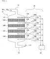
- Fig. 1 schematically shows a configuration of a flue gas NO x removal apparatus equipped with an NO x removal catalyst to which the method of the present invention is applied.
- the flue gas NO x removal apparatus is provided in a thermal power station.
- no particular limitation is imposed on the facility that includes the NO x removal catalyst management unit of the embodiment.
- a flue gas NO x removal apparatus 10 includes an exhaust duct 12 and a treated gas duct 13.
- the exhaust duct 12 is in communication with a boiler unit installed in a thermal power station that is connected with an apparatus body 11 on the upstream side.
- the treated gas duct 13 is connected with the apparatus body 11 on the downstream side.
- a plurality of NO x removal catalyst layers (4 layers in this embodiment) 14A to 14D are disposed at predetermined intervals.
- the NO x removal catalyst layers 14A to 14D are arranged so that a discharge gas introduced through the exhaust duct 12 is sequentially passed therethrough, and reduce the level of nitrogen oxide (NO x ) of the discharge gas through contact with the discharge gas passing through the catalyst layers.
- NH 3 is injected in an amount in accordance with the amount of the discharge gas fed from the boiler body.
- each catalyst is composed of TiO 2 serving as a carrier and V 2 O 5 serving as an active component.
- the catalysts assume the form of honeycomb, plate, etc.
- each catalyst layer employs a catalyst in the form of columnar honeycomb, and a plurality of catalyst layers are arranged in combination, thereby forming the catalyst layers 14A to 14D.
- An NO x removal catalyst management unit 20 is provided with gas sampling means 15A through 15E on the inlet and outlet sides of respective NO x removal catalyst layers 14A through 14D.
- the gas sampling means 15A through 15E are connected with NO x concentration measurement means 16A through 16E and with NH 3 concentration measurement means 17A through 17E.
- the data obtained by the measurement means are transferred to a percent NO x removal determination means 18 for calculating percent NO x removal and percent NO x removal contribution of the respective NO x removal catalyst layers 14A through 14D.
- the gas sampling means 15A through 15E sample, via sampling tubes, a gas to be sampled in a desired amount and at a desired timing, and subsequently feed the sampled gas to the NO x concentration measurement means 16A through 16E and to the NH 3 concentration measurement means 17A through 17E.
- sampling is carried out during usual operation of the power station, preferably at the nominal load where the amount of gas reaches the maximum, if possible.
- the interval between sampling operations may be prolonged to about six months, and the interval is sufficient for managing the performance of the NO x removal catalyst layers 14A through 14D.
- the sampling is preferably carried out, for example, once every one to two months.
- variation of obtained data increases due to decrease in NH 3 concentration.
- determination of NH 3 concentration is performed at short intervals, and percent NO x removal is calculated from an averaged NH 3 concentration value.
- the percent NO x removal determination means 18 collects the measurement data from the NO x concentration measurement means 16A through 16E and the NH 3 concentration measurement means 17A through 17E, and calculates, from the measurement data, percent NO x removal and percent NO x removal contribution of respective NO x removal catalyst layers 14A through 14D.
- evaluation mole ratio refers to a mole ratio which is predetermined for the purpose of evaluating an NO x removal catalyst.
- the evaluation mole ratio may be predetermined to an arbitrary value; for example, 0.8, which is almost equal to a mole ratio typically employed for operating a power station.
- percent NO x removal ( ⁇ ) of respective NO x removal catalyst layers 14A through 14D is determined through a technique on the basis of the inlet mole ratio, and the performance of the catalysts is managed on the basis of the determined percent NO x removal values.
- percent NO x removal ( ⁇ ) of a certain catalyst drops below a predetermined level, the catalyst exhibiting deteriorated performance undergoes the regeneration method of the present invention for restoring catalytic performance.
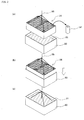
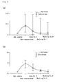
- Fig. 2 illustrates a procedure of carrying out a method according to an embodiment of the present invention.
- an NO x removal catalyst layer 14 to be subjected to regeneration treatment employs a plurality of NO x removal catalysts 14', each assuming the form of columnar honeycomb, arranged in combination.
- a regeneration tank 30 having such dimensions as to be able to accommodate the catalyst layer 14 is provided.
- the regeneration tank 30 contains regeneration water 31 containing substantially no chlorine (pure water in the embodiment).
- the regeneration water contains substantially no chlorine, in view that chlorine inhibits catalytic activity.
- the regeneration water 31 is virtually neutral, and contains no components which are conventionally employed for cleaning; e.g., acids, alkali substances, and other additives.
- the temperature of the regeneration water may be ambient temperature, and no particular heating is required.
- the term "ambient temperature” refers to a temperature falling within a range of, for example, about 5°C to about 40°C.
- the regeneration water 31 may be used repeatedly. Needless to say, during its second use the regeneration water 31 contains components which have been eluted during the first regeneration treatment.
- the NO x removal catalyst layer 14 is suspended by means of a crane 35 or a similar apparatus (Fig. 2(a)), and the catalyst layer 14 is immersed in regeneration water 31 accommodated in the regeneration tank 30 (Figs. 2(b) to 2(c)).
- the time required for immersion is some minutes or longer, and equal to a roughly estimated period of time for completing bubbling from the NO x removal catalyst layer 14; e.g., about 1 to 30 minutes, preferably 5 to 15 minutes.
- the above regeneration effect is attributed to the effect of immersion of a catalyst in regeneration water.
- the immersion-based method enables elution of inhibitors within in a shorter time (see Example 7 mentioned below) as compared with washing by shower, thereby remarkably restoring percent NO x removal.
- the amount of regeneration water 31 may be such an amount as to completely immerse the NO x removal catalyst layer 14. However, regeneration water is preferably used in an amount of 2 to 3 times or more the volume of the NO x removal catalyst layer 14.
- the NO x removal catalyst layer 14 is removed from regeneration water, and water is removed from the catalyst layer. No particular drying step is required. That is, the NO x removal catalyst layer 14 from which water has been removed may be installed in a flue gas NO x removal apparatus, followed by operating the apparatus. Such an undried catalyst layer is sufficiently dried by hot gas flow produced upon startup of the apparatus employing gas oil as a fuel. Needless to say, the catalyst layer may be dried (e.g., dried under sunlight) before installation.
- the catalyst layer may be washed with water by showering.
- water containing substantially no chlorine is used.
- showering is required particularly in the case where the regeneration water 31 has been repeatedly used.
- the main purpose of washing by showering is to wash out foreign matter such as dust deposited on a surface of the NO x removal catalyst layer 14.
- the thus-regenerated NO x removal catalyst layer may be installed again in a flue gas NO x removal apparatus in its original position.
- the catalyst layer may be installed such that the catalyst layer is inverted with respect to the direction of the flow of discharge gas.
- the degree of deterioration of NO x removal catalyst layers is greater in a catalyst layer placed on the upstream side of gas flow.
- inversion of the regenerated catalyst attains delocalization of working portions of an NO x removal catalyst layer.
- this inversion is conceived from the finding of the present applicant that the upstream side of the discharge gas flow exclusively plays a great role in NO x removal reaction.
- the NO x removal catalyst layers which have undergone regeneration treatment exhibit a catalytic activity exhibited by new catalyst layers.
- a portion of a catalyst may be sampled from a regenerated NO x removal catalyst layer, after which the sampled catalyst portion is evaluated in catalytic performance, and the evaluated catalyst layer is re-installed in a flue gas NO x removal apparatus.
- a portion 50 mm ⁇ 50 mm ⁇ 100 mm in length
- is cut from the inlet side of the each NO x removal catalyst layer and set in a performance test machine.
- the test gas is fed under the conditions which match the design values of an actual NO x removal apparatus, and percent NO x removal is determined by measuring NO x concentration and NH 3 concentration on the outlet side of the catalyst sample, thereby evaluation NO x removal performance. Whether or not the catalyst layer has been completely regenerated can be confirmed through the above procedure.
- the regeneration water employed in the method of the present invention has been confirmed to be repeatedly usable about 30 times. Differing from a conventional method such as washing with oxalic acid-based cleaning liquid, the regeneration water which has been used several times contains no heavy metal components. Thus, no particular heavy metal treatment step is required for the regeneration water.
- the regeneration water is advantageous in that it can be treated by a wastewater treatment apparatus that is generally employed in, for example, a thermal power station.
- a conventional abrasion treatment may also be performed. Inhibiting substances which are difficult to remove through abrasion can be completely removed through the method of the present invention.
- the regeneration effect of the present invention can be attained, within a short period of time, by immersing an NO x removal catalyst in regeneration water.
- the regeneration water can be repeatedly used about 30 times.
- washing a deteriorated catalyst with water by showering requires a longer period of time as compared with immersion. If wash water is repeatedly used in showering-based washing, provision of a large-scale pump is required, and nozzles may become plugged. Therefore, a large amount of fresh water must be provided for washing with water by showering.
- Each of the deteriorated NO x removal catalyst layers which had been used for about 63,000 hours in a flue gas NO x removal apparatus (equipped with four NO x removal catalyst layers as shown in Fig. 1) installed in an actual thermal power station employing coal as a fuel was removed from the apparatus.
- the catalyst layer was immersed for the purpose of regeneration at ambient temperature (about 25°C) in pure water for about 10 minutes. After removal of the catalyst layer from water, the catalyst layer was lightly washed by showering.
- the NO x removal catalyst layers which had been regenerated in Working Example 1 were installed again in the flue gas NO x removal apparatus and were further used for about 28,300 hours (for a total of about 91,300 hours). The thus-used catalyst layer was regenerated again in a manner similar to that of Working Example 1.
- Through-holes of an NO x removal catalyst layer were filled with a abrasion agent, and the NO x removal catalyst layer was micro-vibrated in a longitudinal direction of the through-holes, whereby the inner surfaces of the through-holes were subjected to abrasion.
- the degree of abrasion was regulated by modifying the time of micro-vibration. As a result, the inner surfaces were scraped at an average depth of about 40 ⁇ m.
- a portion (50 mm ⁇ 50 mm ⁇ 100 mm in length) was cut from the inlet side of the each NO x removal catalyst layer, and set in a performance test machine.
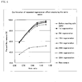
- the results are shown in Fig. 3.
- a new (fresh) catalyst layer, a catalyst layer which had not been regenerated (before regeneration in Working Example 1: used for 63,000 hours), and a catalyst layer which had not been re-regenerated (before regeneration in Working Example 2: used for 28,300 hours after first regeneration) were also measured in terms of percent NO x removal.
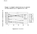
- Percent NO x removal of each of the samples of Working Examples 4 and 5 was determined before and after regeneration in a manner similar to that of Test Example 1. As a reference product, percent NO x removal of a new (fresh) catalyst layer was also determined. Fig. 5 shows the results.
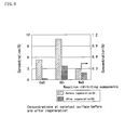
- the results indicate that CaO, SO 3 , and NaO, which are substances inhibiting catalytic activity, have been eluted through regeneration treatment. Increase in TiO 2 concentration and WO 3 concentration at the catalyst surface, which are closely related to catalytic acticity, are confirmed, indicating that the catalytic activity has been restored.
- the results also indicate that ash components such as SiO 2 and Al 2 O 3 , which have conventionally been thought to inhibit catalytic activity, do not greatly affect the catalytic activity. Therefore, even if such ash components are not removed through regeneration treatment, catalytic activity can be sufficiently restored.
- Concentrations (reduced to element) of inhibiting substances (CaO and SO 3 ) on the surface of each of the catalyst samples of Working Examples 1 and 6 and Comparative Example 2 were determined, before and after regeneration, by means of an X-ray microanalyzer. The results are shown in Fig. 7. Each concentration is shown in Fig. 7 with an average value and variance obtained from a plurality of measurements.
- the regeneration method of the present invention is also effective even when performed after conventional abrasion treatment for regeneration.
- Such a mode of combined treatments should also be construed as falling within the scope of the present invention.
- the regeneration water employed in Working Example 1 was analyzed in terms of eluted species.
- As reference and control cleaning liquid samples 0.1N oxalic acid, 1N hydrochloric acid, 0.1N nitric acid, 1N nitric acid, 0.3% EDTA, 3% EDTA, and 5% hydrogen peroxide were employed as cleaning liquids instead of pure water, and the same analysis was performed.
- Table 4 shows the results. All the above treatments were performed at ambient temperature.
Landscapes
- Chemical & Material Sciences (AREA)
- Engineering & Computer Science (AREA)
- Chemical Kinetics & Catalysis (AREA)
- Environmental & Geological Engineering (AREA)
- Analytical Chemistry (AREA)
- Health & Medical Sciences (AREA)
- Biomedical Technology (AREA)
- General Chemical & Material Sciences (AREA)
- Oil, Petroleum & Natural Gas (AREA)
- Organic Chemistry (AREA)
- Materials Engineering (AREA)
- Combustion & Propulsion (AREA)
- Mechanical Engineering (AREA)
- General Engineering & Computer Science (AREA)
- Life Sciences & Earth Sciences (AREA)
- Sustainable Development (AREA)
- Exhaust Gas Treatment By Means Of Catalyst (AREA)
- Catalysts (AREA)
Applications Claiming Priority (3)
| Application Number | Priority Date | Filing Date | Title |
|---|---|---|---|
| JP2002181180A JP4578048B2 (ja) | 2002-06-21 | 2002-06-21 | 脱硝触媒再生方法 |
| JP2002181180 | 2002-06-21 | ||
| PCT/JP2003/007787 WO2004000461A1 (fr) | 2002-06-21 | 2003-06-19 | Procede pour regenerer un catalyseur d'elimination de nox |
Publications (2)
| Publication Number | Publication Date |
|---|---|
| EP1524032A1 true EP1524032A1 (fr) | 2005-04-20 |
| EP1524032A4 EP1524032A4 (fr) | 2005-08-10 |
Family
ID=29996622
Family Applications (1)
| Application Number | Title | Priority Date | Filing Date |
|---|---|---|---|
| EP03760905A Ceased EP1524032A4 (fr) | 2002-06-21 | 2003-06-19 | PROCEDE POUR REGENERER UN CATALYSEUR D'ELIMINATION DE NOx |
Country Status (9)
| Country | Link |
|---|---|
| US (1) | US8980779B2 (fr) |
| EP (1) | EP1524032A4 (fr) |
| JP (1) | JP4578048B2 (fr) |
| KR (1) | KR100601035B1 (fr) |
| CN (1) | CN1329124C (fr) |
| AU (1) | AU2003244308A1 (fr) |
| CA (1) | CA2497604C (fr) |
| TW (1) | TWI282292B (fr) |
| WO (1) | WO2004000461A1 (fr) |
Cited By (1)
| Publication number | Priority date | Publication date | Assignee | Title |
|---|---|---|---|---|
| EP1579913A4 (fr) * | 2002-12-27 | 2009-06-10 | Chugoku Electric Power | Catalyseur en nid d'abeille, catalyseur de denitration de dispositif de denitration, et dispositif de gaz de denitration |
Families Citing this family (19)
| Publication number | Priority date | Publication date | Assignee | Title |
|---|---|---|---|---|
| JP3935417B2 (ja) | 2002-11-01 | 2007-06-20 | 中国電力株式会社 | 脱硝触媒管理方法および脱硝触媒管理装置 |
| CN100408186C (zh) * | 2006-12-30 | 2008-08-06 | 东北大学 | 一种烟气脱氮用催化-吸附剂的再生方法及装置 |
| KR20080114051A (ko) * | 2007-06-26 | 2008-12-31 | 한국전력공사 | 배연탈질 폐촉매의 재생 방법 및 그에 이용되는 배연탈질폐촉매의 세정 시간 결정 방법 |
| US20110015055A1 (en) * | 2009-07-17 | 2011-01-20 | Cooper Michael D | Method for removing a catalyst inhibitor from a substrate |
| US20110015056A1 (en) * | 2009-07-17 | 2011-01-20 | Coalogix Technology Holdings Inc. | Method for removing a catalyst inhibitor from a substrate |
| CN101947414B (zh) * | 2010-09-09 | 2013-04-17 | 南昌航空大学 | 可移动式脱硝催化剂清洗装置 |
| KR20120081918A (ko) * | 2011-01-12 | 2012-07-20 | 지엠텍(주) | Scr 탈질설비 폐촉매 재생시스템의 바나듐 함침조 |
| TWI485355B (zh) * | 2011-12-05 | 2015-05-21 | Mitsubishi Hitachi Power Sys | Vertical flow downflow type smoke denitrification device |
| JP5844943B2 (ja) * | 2013-03-28 | 2016-01-20 | 中国電力株式会社 | 脱硝触媒の再生方法 |
| US9051862B2 (en) | 2013-09-06 | 2015-06-09 | Cummins Ip, Inc. | Diagnosis and treatment of selective catalytic reduction catalyst |
| WO2016172040A1 (fr) * | 2015-04-21 | 2016-10-27 | Cummins Emission Solutions, Inc. | Systèmes et procédés pour l'amélioration d'efficacité catalytique de catalyseurs de réduction catalytique sélective (rcs) |
| KR101885917B1 (ko) * | 2016-12-27 | 2018-08-07 | 대영씨엔이(주) | 유기산을 사용한 폐탈질촉매의 재 소재화 방법 |
| KR101896094B1 (ko) * | 2016-12-27 | 2018-09-07 | 대영씨엔이(주) | 무기산을 사용한 폐탈질촉매의 재 소재화 방법 |
| WO2018123156A1 (fr) * | 2016-12-28 | 2018-07-05 | 栗田工業株式会社 | Procédé et appareil d'élimination de peroxyde d'hydrogène |
| CN108295891B (zh) * | 2018-01-10 | 2021-04-06 | 绍兴文理学院 | 柴油车尾气净化用Cu基分子筛脱硝催化剂的原位再生系统与方法 |
| CN113841009A (zh) | 2019-03-07 | 2021-12-24 | 中国电力株式会社 | 燃烧系统 |
| US20220170403A1 (en) | 2019-03-07 | 2022-06-02 | The Chugoku Electric Power Co., Inc. | Combustion system |
| JP7315921B2 (ja) | 2019-03-07 | 2023-07-27 | 中国電力株式会社 | 燃焼システム |
| JP7716837B2 (ja) * | 2019-11-20 | 2025-08-01 | 三菱重工業株式会社 | 触媒洗浄方法、触媒洗浄装置及びプログラム |
Family Cites Families (24)
| Publication number | Priority date | Publication date | Assignee | Title |
|---|---|---|---|---|
| US4085193A (en) * | 1973-12-12 | 1978-04-18 | Mitsubishi Petrochemical Co. Ltd. | Catalytic process for reducing nitrogen oxides to nitrogen |
| US4164546A (en) * | 1974-12-19 | 1979-08-14 | Exxon Research & Engineering Co. | Method of removing nitrogen oxides from gaseous mixtures |
| JPS5227091A (en) * | 1975-08-27 | 1977-03-01 | Kobe Steel Ltd | Reproduction process of catalyst for removing nitrogen oxides in waste gas |
| JPS53125964A (en) * | 1977-04-12 | 1978-11-02 | Nippon Steel Corp | Continuous treatment apparatus for exhaust gas from fixed source |
| JPS5962350A (ja) * | 1982-10-04 | 1984-04-09 | Mitsubishi Heavy Ind Ltd | 触媒の再生法 |
| JPS6480444A (en) | 1987-09-22 | 1989-03-27 | Mitsubishi Heavy Ind Ltd | Regeneration of denitration catalyst |
| JPH01119343A (ja) | 1987-11-04 | 1989-05-11 | Ishikawajima Harima Heavy Ind Co Ltd | 脱硝触媒の再生処理方法 |
| JPH04197451A (ja) | 1990-11-29 | 1992-07-17 | Japan Carlit Co Ltd:The | 脱硝触媒の再生方法 |
| JP2994769B2 (ja) | 1991-02-15 | 1999-12-27 | 三菱重工業株式会社 | 脱硝触媒再生液の処理方法 |
| JPH07116523A (ja) | 1993-10-28 | 1995-05-09 | Ishikawajima Harima Heavy Ind Co Ltd | 脱硝触媒の再生方法および再生装置 |
| JP3150519B2 (ja) | 1994-02-16 | 2001-03-26 | 三菱重工業株式会社 | 脱硝触媒の再生方法 |
| JPH08196920A (ja) | 1995-01-25 | 1996-08-06 | Nippon Steel Corp | 脱硝触媒の再生方法 |
| DE19628212B4 (de) * | 1996-07-12 | 2008-06-05 | Enbw Energy Solutions Gmbh | Verfahren zum Reinigen und/oder Regenerieren von ganz oder teilweise desaktivierten Katalysatoren zur Entstickung von Rauchgasen |
| JPH10156192A (ja) | 1996-12-03 | 1998-06-16 | Ishikawajima Harima Heavy Ind Co Ltd | 脱硝触媒の活性再生方法及び装置 |
| JP3873344B2 (ja) | 1996-12-03 | 2007-01-24 | 石川島播磨重工業株式会社 | 脱硝触媒の活性再生方法及び装置 |
| JP3377715B2 (ja) | 1997-02-27 | 2003-02-17 | 三菱重工業株式会社 | 脱硝触媒の再生方法 |
| JP3915173B2 (ja) | 1997-06-09 | 2007-05-16 | 石川島播磨重工業株式会社 | 脱硝触媒の活性再生方法及び装置 |
| DE19829916B4 (de) * | 1998-07-06 | 2005-03-24 | Envica Gmbh | Verfahren zur Regeneration von Katalysatoren und regenerierte Katalysatoren |
| JP3059136B2 (ja) | 1998-07-24 | 2000-07-04 | 三菱重工業株式会社 | 脱硝触媒の再生方法 |
| ATE209963T1 (de) * | 1998-08-26 | 2001-12-15 | Integral Umwelt Und Anlagentec | Verfahren zur regenerierung von gebrauchten denox-bzw. dedioxin-katalysatoren |
| JP2000107612A (ja) | 1998-09-30 | 2000-04-18 | Catalysts & Chem Ind Co Ltd | 脱硝触媒の再生方法 |
| CZ302209B6 (cs) * | 1999-11-12 | 2010-12-22 | Babcock@Hitachi@Kabushiki@Kaisha | Zpusob@rozkládání@organických@sloucenin@obsahujících@chlor@@které@jsou@obsaženy@ve@spalinách@@a@katalyzátor@pro@použití@pri@tomto@zpusobu |
| US6482762B1 (en) * | 2000-08-14 | 2002-11-19 | Atlantic Richfield Company | NOx conversion catalyst rejuvenation process |
| US20040074809A1 (en) * | 2002-10-21 | 2004-04-22 | George Yaluris | Reduction of gas phase reduced nitrogen species in partial burn FCC processes |
-
2002
- 2002-06-21 JP JP2002181180A patent/JP4578048B2/ja not_active Expired - Lifetime
-
2003
- 2003-06-19 US US10/518,627 patent/US8980779B2/en not_active Expired - Fee Related
- 2003-06-19 AU AU2003244308A patent/AU2003244308A1/en not_active Abandoned
- 2003-06-19 CA CA2497604A patent/CA2497604C/fr not_active Expired - Fee Related
- 2003-06-19 WO PCT/JP2003/007787 patent/WO2004000461A1/fr not_active Ceased
- 2003-06-19 EP EP03760905A patent/EP1524032A4/fr not_active Ceased
- 2003-06-19 KR KR1020047020854A patent/KR100601035B1/ko not_active Expired - Fee Related
- 2003-06-19 CN CNB038198169A patent/CN1329124C/zh not_active Expired - Fee Related
- 2003-06-20 TW TW092116790A patent/TWI282292B/zh not_active IP Right Cessation
Cited By (1)
| Publication number | Priority date | Publication date | Assignee | Title |
|---|---|---|---|---|
| EP1579913A4 (fr) * | 2002-12-27 | 2009-06-10 | Chugoku Electric Power | Catalyseur en nid d'abeille, catalyseur de denitration de dispositif de denitration, et dispositif de gaz de denitration |
Also Published As
| Publication number | Publication date |
|---|---|
| US8980779B2 (en) | 2015-03-17 |
| JP4578048B2 (ja) | 2010-11-10 |
| AU2003244308A1 (en) | 2004-01-06 |
| EP1524032A4 (fr) | 2005-08-10 |
| CA2497604C (fr) | 2010-08-17 |
| WO2004000461A1 (fr) | 2003-12-31 |
| KR20050079626A (ko) | 2005-08-10 |
| TW200403104A (en) | 2004-03-01 |
| TWI282292B (en) | 2007-06-11 |
| CA2497604A1 (fr) | 2003-12-31 |
| CN1674992A (zh) | 2005-09-28 |
| KR100601035B1 (ko) | 2006-07-18 |
| US20060058176A1 (en) | 2006-03-16 |
| CN1329124C (zh) | 2007-08-01 |
| JP2005199108A (ja) | 2005-07-28 |
Similar Documents
| Publication | Publication Date | Title |
|---|---|---|
| US8980779B2 (en) | Method of regenerating NOx removal catalyst | |
| CN103781549B (zh) | 减小脱硝催化剂的so2氧化率升高的方法 | |
| US7723251B2 (en) | Method of regeneration of SCR catalyst | |
| JP2013056319A5 (fr) | ||
| US20090155132A1 (en) | Honeycomb catalyst, denitration catalyst of denitration device, and exhaust gas denitration device | |
| US20140274661A1 (en) | Methods of removing calcium material from a substrate or catalytic converter | |
| CA2548444C (fr) | Methode de restauration des caracteristiques de marche d'un dispositif de traitement des gaz d'echappement | |
| EP1514590A1 (fr) | Procede et appareil pour surveiller le catalyseur d'elimination de nox du denitrifieur | |
| CN105142760A (zh) | 使用碱性水溶液和抗氧剂从催化转化器去除铁材料的方法 | |
| JP2007160268A (ja) | 脱硝触媒の再生処理方法 | |
| JP2010029864A (ja) | 排ガス処理装置の性能回復方法 | |
| KR100880236B1 (ko) | 배기 가스 처리 장치의 성능 회복 방법 | |
| US20110015056A1 (en) | Method for removing a catalyst inhibitor from a substrate | |
| JP4944588B2 (ja) | 触媒用金属基板、及び板状脱硝触媒の製造方法 | |
| US20110015055A1 (en) | Method for removing a catalyst inhibitor from a substrate |
Legal Events
| Date | Code | Title | Description |
|---|---|---|---|
| PUAI | Public reference made under article 153(3) epc to a published international application that has entered the european phase |
Free format text: ORIGINAL CODE: 0009012 |
|
| 17P | Request for examination filed |
Effective date: 20041223 |
|
| AK | Designated contracting states |
Kind code of ref document: A1 Designated state(s): AT BE BG CH CY CZ DE DK EE ES FI FR GB GR HU IE IT LI LU MC NL PT RO SE SI SK TR |
|
| AX | Request for extension of the european patent |
Extension state: AL LT LV MK |
|
| A4 | Supplementary search report drawn up and despatched |
Effective date: 20050624 |
|
| RIC1 | Information provided on ipc code assigned before grant |
Ipc: 7B 01D 53/56 B Ipc: 7B 01J 38/48 A |
|
| DAX | Request for extension of the european patent (deleted) | ||
| 17Q | First examination report despatched |
Effective date: 20150720 |
|
| APBK | Appeal reference recorded |
Free format text: ORIGINAL CODE: EPIDOSNREFNE |
|
| APBN | Date of receipt of notice of appeal recorded |
Free format text: ORIGINAL CODE: EPIDOSNNOA2E |
|
| APBR | Date of receipt of statement of grounds of appeal recorded |
Free format text: ORIGINAL CODE: EPIDOSNNOA3E |
|
| APAF | Appeal reference modified |
Free format text: ORIGINAL CODE: EPIDOSCREFNE |
|
| REG | Reference to a national code |
Ref country code: DE Ref legal event code: R003 |
|
| APBT | Appeal procedure closed |
Free format text: ORIGINAL CODE: EPIDOSNNOA9E |
|
| STAA | Information on the status of an ep patent application or granted ep patent |
Free format text: STATUS: THE APPLICATION HAS BEEN REFUSED |
|
| 18R | Application refused |
Effective date: 20190823 |