EP1523946B1 - Clip-operationsgerät - Google Patents
Clip-operationsgerät Download PDFInfo
- Publication number
- EP1523946B1 EP1523946B1 EP03741426A EP03741426A EP1523946B1 EP 1523946 B1 EP1523946 B1 EP 1523946B1 EP 03741426 A EP03741426 A EP 03741426A EP 03741426 A EP03741426 A EP 03741426A EP 1523946 B1 EP1523946 B1 EP 1523946B1
- Authority
- EP
- European Patent Office
- Prior art keywords
- clip
- distal end
- manipulating
- wire
- end portion
- Prior art date
- Legal status (The legal status is an assumption and is not a legal conclusion. Google has not performed a legal analysis and makes no representation as to the accuracy of the status listed.)
- Expired - Lifetime
Links
Images


Classifications
-
- A—HUMAN NECESSITIES
- A61—MEDICAL OR VETERINARY SCIENCE; HYGIENE
- A61B—DIAGNOSIS; SURGERY; IDENTIFICATION
- A61B17/00—Surgical instruments, devices or methods
- A61B17/12—Surgical instruments, devices or methods for ligaturing or otherwise compressing tubular parts of the body, e.g. blood vessels or umbilical cord
- A61B17/128—Surgical instruments, devices or methods for ligaturing or otherwise compressing tubular parts of the body, e.g. blood vessels or umbilical cord for applying or removing clamps or clips
- A61B17/1285—Surgical instruments, devices or methods for ligaturing or otherwise compressing tubular parts of the body, e.g. blood vessels or umbilical cord for applying or removing clamps or clips for minimally invasive surgery
-
- A—HUMAN NECESSITIES
- A61—MEDICAL OR VETERINARY SCIENCE; HYGIENE
- A61B—DIAGNOSIS; SURGERY; IDENTIFICATION
- A61B17/00—Surgical instruments, devices or methods
- A61B17/12—Surgical instruments, devices or methods for ligaturing or otherwise compressing tubular parts of the body, e.g. blood vessels or umbilical cord
- A61B17/122—Clamps or clips, e.g. for the umbilical cord
- A61B17/1227—Spring clips
-
- A—HUMAN NECESSITIES
- A61—MEDICAL OR VETERINARY SCIENCE; HYGIENE
- A61B—DIAGNOSIS; SURGERY; IDENTIFICATION
- A61B17/00—Surgical instruments, devices or methods
- A61B17/00234—Surgical instruments, devices or methods for minimally invasive surgery
- A61B2017/00292—Surgical instruments, devices or methods for minimally invasive surgery mounted on or guided by flexible, e.g. catheter-like, means
- A61B2017/003—Steerable
-
- A—HUMAN NECESSITIES
- A61—MEDICAL OR VETERINARY SCIENCE; HYGIENE
- A61B—DIAGNOSIS; SURGERY; IDENTIFICATION
- A61B90/00—Instruments, implements or accessories specially adapted for surgery or diagnosis and not covered by any of the groups A61B1/00 - A61B50/00, e.g. for luxation treatment or for protecting wound edges
- A61B90/03—Automatic limiting or abutting means, e.g. for safety
- A61B2090/037—Automatic limiting or abutting means, e.g. for safety with a frangible part, e.g. by reduced diameter
Definitions
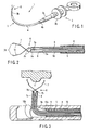
- a side-viewing endoscope 56 is furnished with a forceps raising device 57 in the distal end opening of its channel.
- the forceps raising device 57 is used to raise a clip device 58 and guide the clip device 58 into the region to be treated in the body cavity.
- the present invention provides a clip manipulating device having the features recited in claim 1. Preferred features of the invention are recited in the dependent claims.
- the present invention is a clip manipulating device, in which a coupling member is provided on the distal end of a manipulating member, which is passed for movement through a flexible insertion tube capable of being inserted into a cavity of a living body, and a wire, extending from the clip and pliable enough to follow up deformation of the insertion tube, is coupled to the coupling member.
- the respective distal end portions of the arm portions 7c are bent toward each other so that the two bent parts serve as nipping portions 7d, individually.
- the pair of arm portions 7c are given aptitude for spreading such that the opposed nipping portions 7d are kept wide apart, as shown in FIG. 2 .
- the proximal end side part of the manipulating wire 9 passes through the coil sheath 5 of the insertion section 2 to reach a longitudinally movable slider 3b on the control section 3, and is connected to the slider 3b.
- the pair of nipping portions 7d of the clip 7 in the spread state are pressed against the affected region 11, and the manipulating wire 9 is hauled and retreated by pulling the slider 3b toward the proximal end as it is. Thereupon, the respective proximal end portions of the arm portions 7c of the clip 7 are drawn into the retainer pipe 8, and the arm portions 7c of the clip 7 are closed to grasp the affected region 11, as shown in FIG. 4 .
- the whole manipulating wire 9 is pliable, including the distal junction formed of that part of the wire which is situated behind the anchor portion 7e of the clip 7, and includes no rigid portions.
- the wire can be smoothly moved in the coil sheath 5 without being easily caught by that part of the coil sheath 5 which is bent by means of the forceps raising device 10b.
- the manipulating wire 9 can be quickly advanced and retreated in the coil sheath 5 to ensure smooth manipulation. If the coil sheath 5 is deeply bent by means of the forceps raising device 10b in the side-viewing endoscope 10, in particular, the movement in the coil sheath 5 cannot be hindered.
- the clip manipulating device 1 can be operated securely and quickly even in the side-viewing endoscope 10.
- the clip or the clip unit is provided with the anchor portion that is released from the manipulating means of the manipulating wire 9 by means of the tractive effort of the given or higher value when it is hauled by the manipulating means with the tractive effort. Accordingly, rigid regions on the manipulating means side can be eliminated or reduced. Even when the insertion tube is in the bent state, therefore, the coupling means can be smoothly moved in the insertion tube without hitching with ease.
- a clip manipulating device according to a second configuration, which does not form part of the invention, will be described with reference to FIGS. 5A to 5D .
- a clip manipulating device 12 has the following construction.
- a sheath member that is equivalent to the tube sheath 4 forms a coil sheath 13.
- a cylindrical distal tip 14, which has a diameter smaller than the inside diameter of the coil sheath 13, is coaxially mounted and fixed on the distal end of the coil sheath 13.
- a manipulating wire 15 to be coupled to a clip unit 6 is passed through a sheath-shaped push member 17 (mentioned later) in the coil sheath 13 as it is guided to the handling side through the coil sheath 13.
- the clip unit 6 is composed of a clip 7, which is formed in the same manner as the one according to the foregoing first configuration, and a clamp ring 16 formed of resin or metal having satisfactory strength and elasticity.
- the clamp ring 16 has, on its outer peripheral region, a pair of or a plurality of collapsible blades 16a and 16a' as elastic projections that can be elastically deformed and project outward.
- the elastic projections are not limited to blade-shaped projections, and may be replaced with an elastic projecting ring or the like that encircles the clamp ring 16.
- the anchor portion 7e for use as a wire connecting portion is provided on the rear end of the clip 7.
- the looped portion (junction) 15a of the manipulating wire 15 is coupled to the anchor portion 7e for detachable engagement.
- the anchor portion 7e like the one according to the foregoing first configuration, is configured to be detachably coupled with the looped distal end portion of the manipulating wire 9 that is passed through the coil sheath 5.
- the anchor portion 7e is elongated to release the manipulating wire 9 for use as manipulating means (mentioned later) by means of a tractive effort of a given or higher value when the manipulating wire 9 is hauled with the tractive effort.
- That part of the manipulating wire 15 which is also situated behind the anchor portion 7e of the clip 7 includes no rigid portions.
- the present configuration shares other configurations with the first configuration mentioned before.
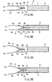
- the push member 17 is advanced by means of the slider 3b of the control section 3 so that the clip unit 6 is temporarily projected from the distal end of the coil sheath 13, as shown in FIG. 5B .
- the coil sheath 13, receded from the distal tip 14, is suitably raised by means of the forceps raising device of the endoscope, and the clip 7 is guided toward the affected region 11 in the patient's body.
- the slider 3b With the clip 7 pressed against the affected region 11, the slider 3b is pulled toward the handling side, and the manipulating wire 15 is hauled. Thereupon, retractable portions 7b of the clip 7 are drawn into the clamp ring 16, and the retractable portions 7b are squeezed so that the clip 7 spreads, as shown in FIG. 5C .
- the clip 7 can be closed to grasp the affected region 11. If the manipulating wire 15 is hauled and retreated with the affected region 11 nipped by means of the clip 7, the anchor portion 7e of the clip 7 is deformed and elongated straight so that it is disengaged from the junction at the distal end of the manipulating wire 15, as shown in FIG. 5D , whereupon the clip unit 6 leaves the insertion section 2. As shown in FIG. 5D , the clip 7 is confined in the patient's body without ceasing to nip the affected region 11.
- the present configuration has the effect that the manipulation is easy, besides the same effects of the first configuration.
- the clip 7 is constructed substantially in the same manner as the one according to the first configuration mentioned before. In the present configuration, however, it is not provided with the anchor portion 7e, and a looped portion at a proximal end portion 7a of the clip 7 is formed as an anchor portion for wire connection. The distal end wire portion of the manipulating wire 19 is passed through and anchored to the looped portion.
- the distal end portion of the manipulating wire 19 is formed by passing one pliable wire member through the looped portion at the proximal end portion 7a of the clip 7 and turning it backward, and then intertwining the backwardly turned wire portion with the remaining original part of the manipulating wire 19, thereby forming a stranded portion 19a for connection.
- the manipulating wire 19 is the weakest part of the wire member.
- the pliable coupling member portion can be formed having no rigid portions on that part of the manipulating wire 19 which is situated behind the proximal end portion 7a of the clip 7.
- a cylindrical distal tip 21 is provided on the distal end of the coil sheath 5.
- the distal end portion of the distal tip 21 is fitted on the small-diameter portion 20a on the outer periphery of the rear end portion of the retainer pipe 20.
- the rear end portion of the distal tip 21 is fitted and mounted on the outer periphery of the distal end portion of the coil sheath 5.
- a clip manipulating device according to a fourth configuration, which does not form part of the invention, will be described with reference to FIGS. 8A to 13 .
- a clip manipulating device 22 for organic tissue is constructed in the following manner.
- an insertion section 2 is formed of a coil sheath 23, and a distal tip 24 is fixedly attached to the distal end of the coil sheath 23.
- a clip setting portion that detachably stores the clip and controls the clip in open-close action and plastic deformation.
- the inner wall portion of the distal tip 24 is formed having a pair of slope portions 24a, which are axisymmetrically located above and below so that they are more distant from each other on the distal end side.
- the pair of slope portions 24a range from the distal end of the distal tip 24 to the middle.
- a large-diameter hole 24b that is continuous with the respective rear end edges of the slope portions 24a is defined in that part which is situated on the rear end side of the rear end edges of the slope portions 24a.
- a pair of projections 24c are formed individually on the respective rear ends of the slope portions 24a. The projections 24c are formed by utilizing projecting end edges on the boundary between the slope portions 24a and the large-diameter hole 24b.
- a manipulating wire 19, like the aforesaid one according to the third configuration has a pliable junction (coupling means) on its wire distal end side part. More specifically, the wire distal end side part of the manipulating wire 19 is passed through a looped portion of the proximal end portion 25a of the clip 25 and doubled. The turned wire portion is led backward and intertwined and joined with the remaining original wire portion, whereupon a stranded portion 19a is formed. Also in the present configuration, therefore, there are no rigid portions on that part of the manipulating wire 19 which is situated behind the proximal end portion 25a of the clip 25.
- the coil sheath 23 and the manipulating wire 19 are connected to the body 3a of the control section 3 and the slider 3b, respectively.
- the respective proximal end side parts of the arm portions 25b of the clip 25 are encased in the distal tip 24, as shown in FIGS. 8A and 8B .
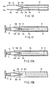
- the insertion section 2 of the clip manipulating device 12 is guided into the body cavity through the channel of the endoscope.
- the slider 3b of the control section 3 is advanced a little way, and the manipulating wire 19 is loosened to advance the clip 25 for a short distance.
- the arm portions 25b are spread by the aptitude of the clip 25 for spreading, as shown in FIGS. 9A and 9B .
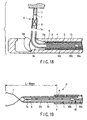
- the forceps raising device of the endoscope is manipulated so that the clip 25 is guided into the affected region 11 in the body cavity, as shown in FIG. 11 .
- the manipulating wire 19 is advanced to spread and press the clip 25 against the affected region 11.
- the manipulating wire 19 is pulled by means of the slider with the clip 25 pressed against the affected region 11.
- the clip 25 is closed to grasp the affected region 11, as shown in FIG. 11 .
- the proximal end portion 25a of the clip 25 is plastically deformed by the projections 24c of the distal tip 24. After the projections 24c are cleared, the projections 24c are fitted individually into the recesses 25d of the clip 25, thereby anchoring the clip 25.
- the stranded portion 19a loosens, as shown in FIG. 12 .
- the manipulating wire 19 is disengaged from the proximal end portion 25a of the clip 25.
- the clip 25 is allowed to be disengaged sideways from the slit 24d of the distal tip 24. As shown in FIG. 13 , the clip 25 can be disengaged from the distal tip 24 and confined in the patient's body without ceasing to nip the affected region 11.
- the present configuration also has an effect that the device requires fewer components and can be manufactured at low cost. Further, manipulation can be simplified. Since the arm portions 25b of the clip 25 is fitted in the distal tip 24, moreover, dislocation between the unit of the clip 25 and the coil sheath 13 can be prevented when the forceps is raised, for example.
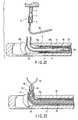
- a clip manipulating device according to an embodiment of the present will be described with reference to FIGS. 14 and 15 .
- a clip manipulating device 26 for organic tissue differs from the third configuration in the configuration of a manipulating wire 27.
- the manipulating wire 27 of the present embodiment comprises a driving wire 27a, which is situated on the handling side, and a doubled thread 27c for use as a junction (coupling means) that is connected to the distal end of driving wire 27a by means of a joint 27b.
- a looped distal end portion of the doubled thread 27c serves as a junction that is anchored to a clip 7. That part (junction) of the thread 27c which is to be turned is passed through a proximal end portion (anchor portion) 7a of the clip 7 and anchored.
- the turned wire portion of the thread 27c forms a weak point and snaps, whereupon the clip 7 is released.
- the joint 27b is situated behind an exposed portion 5b of a coil sheath 5.
- the driving wire 27a for use as the manipulating means couples the thread 27c as a flexible coupling member to the clip 7, and the joint 27b is located in a position at a suitable distance from the distal end of the coil sheath 5.
- the disengagement means according to the present embodiment that allows the wire portion to snap and release the clip 7 is also applicable to the first configuration mentioned before. Also available is an arrangement such that the wire portion of the stranded portion 19a according to the foregoing third configuration loosens so that the manipulating wire 19 is disengaged from the proximal end portion 7a of the clip 7.
- Clip manipulating devices according to a fifth configuration which does not form part of the invention, will be described with reference to FIGS. 16 to 20 .
- Clip manipulating devices 29 and 31 according to the present configuration differ from the one according to the first configuration in an anchoring structure for a manipulating wire 30 and a clip 7.
- the clip manipulating device 29 comprises a portion corresponding to a driving wire 30a of the manipulating wire 30 on the handling side and a doubled wire 30c that is connected to the distal end of the driving wire 30a by means of a joint 30b, as shown in FIG. 16 . More specifically, in the doubled wire 30c, a turned distal end portion is hitched and connected to an anchor portion 7e of the clip 7, thereby forming a pliable coupling member portion.
- the doubled wire 30c is relatively long.
- the joint 30b is situated behind a position A at a distance L of 30 mm from the distal end of the clip 7, overreaching a range that covers at least a range corresponding to a movable range area that corresponds to the raising device of the endoscope.
- the joint 30b is always situated in a tube sheath 4 without projecting forward from the distal end of the tube sheath 4 or being exposed, as shown in FIGS. 16 and 17 .
- a clip manipulating device 31 is constructed in like manner, as shown in FIG. 19 .
- the clip manipulating device 31 differs from the aforesaid one in that the basal part of the turned distal end portion of the doubled wire 30c is fastened so that the distal end side portion forms a looped portion. This looped portion is hitched to the anchor portion 7e of the clip 7.
- the following is a description of the operation of the device according to the present configuration.
- the device is used in the steps of procedure shown in FIGS. 16 to 18 .
- the present configuration shares this method of use with the first configuration.
- the joint 30b of the manipulating wire 30 can never get into the range from the distal end of the clip 7 to the position A at the backward distance of 30 mm from it. Further, it never passes through the range of the backward distance L of 30 mm from the distal end of the clip 7. Therefore, the joint 30b constitutes no hindrance to operation if it is rigid.
- the clip manipulating device 31 shown in FIG. 19 is a modification of the foregoing clip manipulating device 29 according to the fifth configuration.
- the manipulating method for the disengagement of a clip unit 6 of the clip manipulating device 31 is different from the method for the clip manipulating device 29 according to the fifth configuration.
- the joint 30b of the manipulating wire 30 can never get into the range from the distal end of the clip 7 to the position A at the backward distance of 30 mm from it.
- the joint 30b a rigid portion, never passes through the range of the backward distance L of 30 mm from the distal end of the clip 7, so that the same effects of the first configuration can be obtained.
- a part of the manipulating wire 30 is formed into the thick driving wire 30a, so that the force transmission performance is improved further.
- a clip manipulating device according to a sixth configuration, which does not form part of the invention, will be described with reference to FIGS. 21 and 22 .
- a clip unit 6 of a clip manipulating device 32 comprises a clip 7, a pliable looped wire 33 for use as a flexible connecting member hitched to the proximal end of the clip 7, and a retainer pipe 8.
- a hook 35 is provided on the distal end of a manipulating wire 34 for use as manipulating means.
- a coupling plate 36 is removably mounted on the hook 35, and the clip unit 6 is coupled to the coupling plate 36 of the manipulating wire 34 by means of the looped wire 33.
- the coupling plate 36 is formed having a J-shaped portion 36a as deformable anchor means on its distal end portion.
- the proximal end portion of the looped wire 33 is hitched to the anchoring J-shaped portion 36a, and the hook 35 is detachably coupled to the hook 35.
- the hook 35 and the coupling plate 36 are situated behind a position A at a backward distance L of 30 mm from the distal end of the clip 7, so that they cannot be projected and exposed through the distal end of the tube sheath 4.
- the present configuration shares the effects with the fifth configuration mentioned before.
- the present invention is not limited to the embodiments described above, and may be applied to any other configurations.
- the coupling means that is detachably coupled to the clip or the clip unit is not less pliable than enough to follow up the shape of the insertion tube. Even when the insertion tube is in the bent state, therefore, the coupling means can be smoothly moved in the insertion tube without hitching with ease.
- the clip or the clip unit is provided with the anchor portion that is released from the manipulating means by means of the driving force of the given or higher value when it is driven by the manipulating means with the driving force. Accordingly, rigid regions on the manipulating means side can be reduced. Even when the insertion tube is in the bent state, therefore, the coupling means can be smoothly moved in the insertion tube without hitching with ease.
- the coupling means that is coupled to the clip or the clip unit and is released from the clip or the clip unit by means of the driving force of the given or higher value when it is driven with the driving force, is flexible. Even when the insertion tube is in the bent state, therefore, the coupling means can be smoothly moved in the insertion tube without hitching with ease.
- the clip or the clip unit 6 is coupled with the flexible joint in the position at the suitable distance from the distal end of the insertion tube. Even when the insertion tube is in the bent state, therefore, any member of the coupling anchor means can be smoothly moved in the insertion tube without hitching with ease.
- the manipulating means that is coupled to the clip or the clip unit in the distal end of the insertion tube can be manipulated securely and quickly.
- the clip or the clip unit is coupled to the manipulating means by means of the flexible connecting member that is coupled to the clip or the clip unit.
- the connecting member and the manipulating means are coupled by means of the anchor means that is located in the position at the suitable distance from the distal end of the insertion tube.
- the anchor portion releases the connecting member and the manipulating means from connection when the manipulating means is driven with the driving force of the given or higher value. Even when the insertion tube is in the bent state, therefore, any member of the coupling anchor means cannot hitch with ease.
Landscapes
- Health & Medical Sciences (AREA)
- Surgery (AREA)
- Life Sciences & Earth Sciences (AREA)
- Heart & Thoracic Surgery (AREA)
- Nuclear Medicine, Radiotherapy & Molecular Imaging (AREA)
- Vascular Medicine (AREA)
- Engineering & Computer Science (AREA)
- Biomedical Technology (AREA)
- Reproductive Health (AREA)
- Medical Informatics (AREA)
- Molecular Biology (AREA)
- Animal Behavior & Ethology (AREA)
- General Health & Medical Sciences (AREA)
- Public Health (AREA)
- Veterinary Medicine (AREA)
- Surgical Instruments (AREA)
Claims (6)
- Clip-Manipulationsgerät, aufweisend:ein flexibles Einführrohr (5), das in einen Hohlraum eines lebenden Körpers eingeführt werden kann;einen flexiblen Draht (27), der biegbar ist und beweglich durch das Einführrohr (5) verläuft;eine Verbindungsstelle am distalen Endabschnitt des Drahtes (27), der mit einem Clip (7) am distalen Endabschnitt des Einführrohrs (5) lösbar gekoppelt ist, um eine Greif-und Freigabeoperation des Clips (7) zu bewirken,wobei die Verbindungsstelle einen flexiblen Schlingendraht (27c) enthält und ausreichend biegbar ist, um einer starken Biegeverformung des Einführrohrs (5) zu folgen, so dass die Bewegung im Rohr (5) nicht durch die Biegeverformung behindert wird;dadurch gekennzeichnet, dass der flexible Schlingendraht (27c) an seinem distalen Ende mit dem Clip (7) und an seinem proximalen Ende mit dem flexiblen Draht (27) an einer Verbindung (27b) gekoppelt ist; undwobei das distale Ende des flexiblen Schlingendrahtes (27c) so ausgeführt ist, dass es reißt, wenn der Draht (27) mit einer Zugkraft gezogen wird, die groß genug ist, um den Clip (7) freizugeben.
- Clip-Manipulationsgerät nach Anspruch 1, das einen flexiblen Rohrmantel (4) aufweist, der vom Einführrohr (5) zum Vorschub und Rückzug durchdrungen ist, wobei der Rohrmantel (4) den Clip (7) am distalen Endabschnitt des Einführrohrs (5) aufnehmen kann.
- Clip-Manipulationsgerät nach Anspruch 2, bei dem der Teil des Einführrohrs (5), der sich hinter dem Clip (7) befindet und vom distalen Ende des Rohrmantels (4) freigelegt wird, wenn der Clip (7) aus dem Rohrmantel (4) herausragt, einen gekrümmt erhöhten Abschnitt bildet.
- Clip-Manipulationsgerät nach Anspruch 1, bei dem das flexible Einführrohr (5) ein Schiebeelement (17) für den Vorschub des Clips (7) bildet.
- Clip-Manipulationsgerät nach Anspruch 1, bei dem das Einführrohr (5) einen distalen Endabschnitt hat, der gekrümmt sein kann und durch den sich der flexible Schlingendraht (27c) entlang dem gekrümmten distalen Endabschnitt erstreckt, wenn der Clip (7) freigegeben wird, und
sich die Verbindung (27b) bei der Freigabe des Clips (7) entfernt vom gekrümmten distalen Endabschnitt im Einführrohr befindet. - Clip-Manipulationsgerät nach Anspruch 5, bei dem der distale Endabschnitt des Einführrohrs (5) von einem Hubgerät (10b) mit Zange bis zu im Wesentlichen 90° gekrümmt wird.
Applications Claiming Priority (3)
| Application Number | Priority Date | Filing Date | Title |
|---|---|---|---|
| JP2002211371 | 2002-07-19 | ||
| JP2002211371A JP4109030B2 (ja) | 2002-07-19 | 2002-07-19 | 生体組織のクリップ装置 |
| PCT/JP2003/009048 WO2004008975A1 (ja) | 2002-07-19 | 2003-07-16 | クリップ操作装置 |
Publications (3)
| Publication Number | Publication Date |
|---|---|
| EP1523946A1 EP1523946A1 (de) | 2005-04-20 |
| EP1523946A4 EP1523946A4 (de) | 2006-01-04 |
| EP1523946B1 true EP1523946B1 (de) | 2008-12-17 |
Family
ID=30767770
Family Applications (1)
| Application Number | Title | Priority Date | Filing Date |
|---|---|---|---|
| EP03741426A Expired - Lifetime EP1523946B1 (de) | 2002-07-19 | 2003-07-16 | Clip-operationsgerät |
Country Status (5)
| Country | Link |
|---|---|
| US (1) | US20040176784A1 (de) |
| EP (1) | EP1523946B1 (de) |
| JP (1) | JP4109030B2 (de) |
| DE (1) | DE60325365D1 (de) |
| WO (1) | WO2004008975A1 (de) |
Families Citing this family (160)
| Publication number | Priority date | Publication date | Assignee | Title |
|---|---|---|---|---|
| US7491232B2 (en) | 1998-09-18 | 2009-02-17 | Aptus Endosystems, Inc. | Catheter-based fastener implantation apparatus and methods with implantation force resolution |
| US7618426B2 (en) | 2002-12-11 | 2009-11-17 | Usgi Medical, Inc. | Apparatus and methods for forming gastrointestinal tissue approximations |
| US7416554B2 (en) | 2002-12-11 | 2008-08-26 | Usgi Medical Inc | Apparatus and methods for forming and securing gastrointestinal tissue folds |
| US8574243B2 (en) | 1999-06-25 | 2013-11-05 | Usgi Medical, Inc. | Apparatus and methods for forming and securing gastrointestinal tissue folds |
| US7637905B2 (en) | 2003-01-15 | 2009-12-29 | Usgi Medical, Inc. | Endoluminal tool deployment system |
| US20050177180A1 (en) | 2001-11-28 | 2005-08-11 | Aptus Endosystems, Inc. | Devices, systems, and methods for supporting tissue and/or structures within a hollow body organ |
| US20070073389A1 (en) | 2001-11-28 | 2007-03-29 | Aptus Endosystems, Inc. | Endovascular aneurysm devices, systems, and methods |
| US20050070992A1 (en) | 2001-11-28 | 2005-03-31 | Aptus Endosystems, Inc. | Prosthesis systems and methods sized and configured for the receipt and retention of fasteners |
| US9320503B2 (en) | 2001-11-28 | 2016-04-26 | Medtronic Vascular, Inc. | Devices, system, and methods for guiding an operative tool into an interior body region |
| US8231639B2 (en) | 2001-11-28 | 2012-07-31 | Aptus Endosystems, Inc. | Systems and methods for attaching a prosthesis within a body lumen or hollow organ |
| CA2464048C (en) | 2001-11-28 | 2010-06-15 | Lee Bolduc | Endovascular aneurysm repair system |
| ATE383111T1 (de) * | 2002-08-01 | 2008-01-15 | James E Selis | Biopsievorrichtungen |
| US7942898B2 (en) | 2002-12-11 | 2011-05-17 | Usgi Medical, Inc. | Delivery systems and methods for gastric reduction |
| US7942884B2 (en) | 2002-12-11 | 2011-05-17 | Usgi Medical, Inc. | Methods for reduction of a gastric lumen |
| US8216252B2 (en) | 2004-05-07 | 2012-07-10 | Usgi Medical, Inc. | Tissue manipulation and securement system |
| US7347863B2 (en) | 2004-05-07 | 2008-03-25 | Usgi Medical, Inc. | Apparatus and methods for manipulating and securing tissue |
| US20050251189A1 (en) | 2004-05-07 | 2005-11-10 | Usgi Medical Inc. | Multi-position tissue manipulation assembly |
| US7361180B2 (en) | 2004-05-07 | 2008-04-22 | Usgi Medical, Inc. | Apparatus for manipulating and securing tissue |
| GB0402796D0 (en) * | 2004-02-09 | 2004-03-10 | Anson Medical Ltd | An endoluminal surgical delivery system |
| US7703459B2 (en) | 2004-03-09 | 2010-04-27 | Usgi Medical, Inc. | Apparatus and methods for mapping out endoluminal gastrointestinal surgery |
| WO2005104210A2 (en) | 2004-04-20 | 2005-11-03 | Visualsonics Inc. | Arrayed ultrasonic transducer |
| US7390329B2 (en) * | 2004-05-07 | 2008-06-24 | Usgi Medical, Inc. | Methods for grasping and cinching tissue anchors |
| US8257394B2 (en) | 2004-05-07 | 2012-09-04 | Usgi Medical, Inc. | Apparatus and methods for positioning and securing anchors |
| US7736374B2 (en) | 2004-05-07 | 2010-06-15 | Usgi Medical, Inc. | Tissue manipulation and securement system |
| US8444657B2 (en) | 2004-05-07 | 2013-05-21 | Usgi Medical, Inc. | Apparatus and methods for rapid deployment of tissue anchors |
| US8057511B2 (en) | 2004-05-07 | 2011-11-15 | Usgi Medical, Inc. | Apparatus and methods for positioning and securing anchors |
| US7918869B2 (en) | 2004-05-07 | 2011-04-05 | Usgi Medical, Inc. | Methods and apparatus for performing endoluminal gastroplasty |
| US8206417B2 (en) | 2004-06-09 | 2012-06-26 | Usgi Medical Inc. | Apparatus and methods for optimizing anchoring force |
| US7678135B2 (en) | 2004-06-09 | 2010-03-16 | Usgi Medical, Inc. | Compressible tissue anchor assemblies |
| US7695493B2 (en) | 2004-06-09 | 2010-04-13 | Usgi Medical, Inc. | System for optimizing anchoring force |
| US7736379B2 (en) | 2004-06-09 | 2010-06-15 | Usgi Medical, Inc. | Compressible tissue anchor assemblies |
| US8075568B2 (en) | 2004-06-11 | 2011-12-13 | Selis James E | Biopsy devices and methods |
| US8216255B2 (en) * | 2004-06-14 | 2012-07-10 | Ethicon Endo-Surgery, Inc. | Endoscopic clip applier actuator |
| US9763668B2 (en) | 2004-10-08 | 2017-09-19 | Covidien Lp | Endoscopic surgical clip applier |
| US7637917B2 (en) | 2004-10-08 | 2009-12-29 | Tyco Healthcare Group Lp | Endoscopic surgical clip applier |
| ES2616731T3 (es) | 2004-10-08 | 2017-06-14 | Covidien Lp | Aparato para aplicar sujetadores quirúrgicos |
| JP4758173B2 (ja) | 2004-12-24 | 2011-08-24 | オリンパス株式会社 | 結紮装置 |
| US9585651B2 (en) | 2005-05-26 | 2017-03-07 | Usgi Medical, Inc. | Methods and apparatus for securing and deploying tissue anchors |
| US8298291B2 (en) | 2005-05-26 | 2012-10-30 | Usgi Medical, Inc. | Methods and apparatus for securing and deploying tissue anchors |
| US7901358B2 (en) | 2005-11-02 | 2011-03-08 | Visualsonics Inc. | High frequency array ultrasound system |
| US8726909B2 (en) | 2006-01-27 | 2014-05-20 | Usgi Medical, Inc. | Methods and apparatus for revision of obesity procedures |
| US8870916B2 (en) | 2006-07-07 | 2014-10-28 | USGI Medical, Inc | Low profile tissue anchors, tissue anchor systems, and methods for their delivery and use |
| JP4116049B2 (ja) * | 2006-07-25 | 2008-07-09 | オリンパスメディカルシステムズ株式会社 | 生体組織のクリップ装置 |
| JP4497379B2 (ja) * | 2006-08-23 | 2010-07-07 | 朝日インテック株式会社 | 医療用処置具 |
| EP2314232B1 (de) | 2006-10-17 | 2015-03-25 | Covidien LP | Vorrichtung zum Setzen chirurgischer Klammern |
| WO2008118928A2 (en) | 2007-03-26 | 2008-10-02 | Tyco Healthcare Group Lp | Endoscopic surgical clip applier |
| CN102327136B (zh) | 2007-04-11 | 2014-04-23 | 柯惠Lp公司 | 手术施夹器 |
| US20110208212A1 (en) | 2010-02-19 | 2011-08-25 | Zergiebel Earl M | Surgical clip applier |
| US8465502B2 (en) | 2008-08-25 | 2013-06-18 | Covidien Lp | Surgical clip applier and method of assembly |
| US8409223B2 (en) | 2008-08-29 | 2013-04-02 | Covidien Lp | Endoscopic surgical clip applier with clip retention |
| US9358015B2 (en) | 2008-08-29 | 2016-06-07 | Covidien Lp | Endoscopic surgical clip applier with wedge plate |
| US8267944B2 (en) | 2008-08-29 | 2012-09-18 | Tyco Healthcare Group Lp | Endoscopic surgical clip applier with lock out |
| US20110144494A1 (en) | 2008-09-18 | 2011-06-16 | James Mehi | Methods for acquisition and display in ultrasound imaging |
| US9173047B2 (en) | 2008-09-18 | 2015-10-27 | Fujifilm Sonosite, Inc. | Methods for manufacturing ultrasound transducers and other components |
| US9184369B2 (en) | 2008-09-18 | 2015-11-10 | Fujifilm Sonosite, Inc. | Methods for manufacturing ultrasound transducers and other components |
| CA2740867C (en) | 2008-10-16 | 2018-06-12 | Aptus Endosystems, Inc. | Devices, systems, and methods for endovascular staple and/or prosthesis delivery and implantation |
| DE102009022271A1 (de) * | 2009-05-22 | 2010-11-25 | Medi-Globe Gmbh | Applikationsvorrichtung zum Applizieren, insbesondere zum endoskopischen Applizieren eines medizinischen Clips im oder am Körper eines Individuums |
| US9186136B2 (en) | 2009-12-09 | 2015-11-17 | Covidien Lp | Surgical clip applier |
| US8545486B2 (en) | 2009-12-15 | 2013-10-01 | Covidien Lp | Surgical clip applier |
| US8403945B2 (en) | 2010-02-25 | 2013-03-26 | Covidien Lp | Articulating endoscopic surgical clip applier |
| US9044240B2 (en) * | 2010-03-10 | 2015-06-02 | Boston Scientific Scimed, Inc. | Hemostasis clip |
| JP5486983B2 (ja) * | 2010-03-29 | 2014-05-07 | 富士フイルム株式会社 | 結紮装置 |
| US8403946B2 (en) | 2010-07-28 | 2013-03-26 | Covidien Lp | Articulating clip applier cartridge |
| US8968337B2 (en) | 2010-07-28 | 2015-03-03 | Covidien Lp | Articulating clip applier |
| US9011464B2 (en) | 2010-11-02 | 2015-04-21 | Covidien Lp | Self-centering clip and jaw |
| US9186153B2 (en) | 2011-01-31 | 2015-11-17 | Covidien Lp | Locking cam driver and jaw assembly for clip applier |
| BR112013019560A2 (pt) | 2011-02-01 | 2018-07-17 | St Jude Medical | método e dispositivo para o recolhimento de transcateter de tecido de um folíolo de válvula cardíaca. |
| US9775623B2 (en) | 2011-04-29 | 2017-10-03 | Covidien Lp | Surgical clip applier including clip relief feature |
| WO2013067662A1 (zh) * | 2011-11-11 | 2013-05-16 | Zhu Jian | 一种夹持或结扎装置 |
| EP2591736A1 (de) * | 2011-11-14 | 2013-05-15 | Anrei Medical (HZ) Co., Ltd. | Klippvorrichtung zum Abbinden von lebendem Gewebe |
| US20130131697A1 (en) | 2011-11-21 | 2013-05-23 | Covidien Lp | Surgical clip applier |
| US9364239B2 (en) | 2011-12-19 | 2016-06-14 | Covidien Lp | Jaw closure mechanism for a surgical clip applier |
| US9364216B2 (en) | 2011-12-29 | 2016-06-14 | Covidien Lp | Surgical clip applier with integrated clip counter |
| WO2013112795A1 (en) | 2012-01-25 | 2013-08-01 | St. Jude Medical, Inc. | Apparatus and method for heart valve repair |
| US9883855B2 (en) | 2012-01-25 | 2018-02-06 | St. Jude Medical, Llc | Apparatus and method for heart valve repair |
| US10058348B2 (en) | 2012-02-02 | 2018-08-28 | St. Jude Medical, Cardiology Division, Inc. | Apparatus and method for heart valve repair |
| US9265514B2 (en) | 2012-04-17 | 2016-02-23 | Miteas Ltd. | Manipulator for grasping tissue |
| US9408610B2 (en) | 2012-05-04 | 2016-08-09 | Covidien Lp | Surgical clip applier with dissector |
| KR101538828B1 (ko) * | 2012-05-22 | 2015-07-24 | 경북대학교 산학협력단 | 개폐성을 가지는 개폐 클립과 이를 이용한 개폐 클립 처치구 |
| US9532787B2 (en) | 2012-05-31 | 2017-01-03 | Covidien Lp | Endoscopic clip applier |
| US9662205B2 (en) | 2012-08-02 | 2017-05-30 | St. Jude Medical, Cardiology Division, Inc. | Apparatus and method for heart valve repair |
| US10105219B2 (en) | 2012-08-02 | 2018-10-23 | St. Jude Medical, Cardiology Division, Inc. | Mitral valve leaflet clip |
| US9968362B2 (en) | 2013-01-08 | 2018-05-15 | Covidien Lp | Surgical clip applier |
| US9113892B2 (en) | 2013-01-08 | 2015-08-25 | Covidien Lp | Surgical clip applier |
| DE202013100076U1 (de) * | 2013-01-08 | 2013-01-17 | Michael Maurus | Ligatorsystem mit Zwischenring zwischen den Ringbändern |
| US9750500B2 (en) | 2013-01-18 | 2017-09-05 | Covidien Lp | Surgical clip applier |
| US9642706B2 (en) | 2013-03-11 | 2017-05-09 | St. Jude Medical, Llc | Apparatus and method for heart valve repair |
| AU2014308877B2 (en) * | 2013-08-20 | 2018-06-28 | Brigham Young University | Surgical forceps |
| US9775624B2 (en) | 2013-08-27 | 2017-10-03 | Covidien Lp | Surgical clip applier |
| JP6716453B2 (ja) * | 2014-03-31 | 2020-07-01 | 日本ゼオン株式会社 | 内視鏡用処置具 |
| WO2016001382A2 (en) * | 2014-07-02 | 2016-01-07 | Medtentia International Ltd Oy | Clip for a medical implant |
| US10702278B2 (en) | 2014-12-02 | 2020-07-07 | Covidien Lp | Laparoscopic surgical ligation clip applier |
| JP6649899B2 (ja) * | 2014-12-25 | 2020-02-19 | 株式会社カネカ | 医療用クリップ装置および医療用クリップ装置の製造方法 |
| US9931124B2 (en) | 2015-01-07 | 2018-04-03 | Covidien Lp | Reposable clip applier |
| JP6498303B2 (ja) | 2015-01-15 | 2019-04-10 | コヴィディエン リミテッド パートナーシップ | 内視鏡リポーザブル外科手術用クリップアプライヤ |
| US10292712B2 (en) | 2015-01-28 | 2019-05-21 | Covidien Lp | Surgical clip applier with integrated cutter |
| US10159491B2 (en) | 2015-03-10 | 2018-12-25 | Covidien Lp | Endoscopic reposable surgical clip applier |
| EP3305215B1 (de) * | 2015-05-27 | 2025-07-16 | Olympus Corporation | Vorrichtung für ein endoskop |
| CN108348259B (zh) | 2015-11-03 | 2020-12-11 | 柯惠有限合伙公司 | 内窥镜手术夹具施加器 |
| CN108348261B (zh) | 2015-11-10 | 2021-03-16 | 柯惠有限合伙公司 | 可重复使用的内窥镜外科手术施夹器 |
| US10390831B2 (en) | 2015-11-10 | 2019-08-27 | Covidien Lp | Endoscopic reposable surgical clip applier |
| CN108348255B (zh) | 2015-11-10 | 2020-11-27 | 柯惠有限合伙公司 | 可重复使用的内窥镜外科手术施夹器 |
| CA3009420A1 (en) | 2016-01-11 | 2017-07-20 | Peng YI | Endoscopic reposable surgical clip applier |
| US10765431B2 (en) | 2016-01-18 | 2020-09-08 | Covidien Lp | Endoscopic surgical clip applier |
| CA2958160A1 (en) | 2016-02-24 | 2017-08-24 | Covidien Lp | Endoscopic reposable surgical clip applier |
| WO2018027788A1 (en) | 2016-08-11 | 2018-02-15 | Covidien Lp | Endoscopic surgical clip applier and clip applying systems |
| US11071553B2 (en) | 2016-08-25 | 2021-07-27 | Covidien Lp | Endoscopic surgical clip applier and clip applying systems |
| US10660651B2 (en) | 2016-10-31 | 2020-05-26 | Covidien Lp | Endoscopic reposable surgical clip applier |
| US10639044B2 (en) | 2016-10-31 | 2020-05-05 | Covidien Lp | Ligation clip module and clip applier |
| US10610236B2 (en) | 2016-11-01 | 2020-04-07 | Covidien Lp | Endoscopic reposable surgical clip applier |
| US10426489B2 (en) | 2016-11-01 | 2019-10-01 | Covidien Lp | Endoscopic reposable surgical clip applier |
| US10492795B2 (en) | 2016-11-01 | 2019-12-03 | Covidien Lp | Endoscopic surgical clip applier |
| US10709455B2 (en) | 2017-02-02 | 2020-07-14 | Covidien Lp | Endoscopic surgical clip applier |
| US10758244B2 (en) | 2017-02-06 | 2020-09-01 | Covidien Lp | Endoscopic surgical clip applier |
| WO2018141110A1 (en) | 2017-02-06 | 2018-08-09 | Covidien Lp | Surgical clip applier with user feedback feature |
| US10660725B2 (en) | 2017-02-14 | 2020-05-26 | Covidien Lp | Endoscopic surgical clip applier including counter assembly |
| US10603038B2 (en) | 2017-02-22 | 2020-03-31 | Covidien Lp | Surgical clip applier including inserts for jaw assembly |
| US11583291B2 (en) | 2017-02-23 | 2023-02-21 | Covidien Lp | Endoscopic surgical clip applier |
| US10548602B2 (en) | 2017-02-23 | 2020-02-04 | Covidien Lp | Endoscopic surgical clip applier |
| JP6768926B2 (ja) * | 2017-03-22 | 2020-10-14 | 富士フイルム株式会社 | クリップ処置具 |
| US10675043B2 (en) | 2017-05-04 | 2020-06-09 | Covidien Lp | Reposable multi-fire surgical clip applier |
| US10722235B2 (en) | 2017-05-11 | 2020-07-28 | Covidien Lp | Spring-release surgical clip |
| US10660723B2 (en) | 2017-06-30 | 2020-05-26 | Covidien Lp | Endoscopic reposable surgical clip applier |
| US10639032B2 (en) | 2017-06-30 | 2020-05-05 | Covidien Lp | Endoscopic surgical clip applier including counter assembly |
| US10675112B2 (en) | 2017-08-07 | 2020-06-09 | Covidien Lp | Endoscopic surgical clip applier including counter assembly |
| US10932790B2 (en) | 2017-08-08 | 2021-03-02 | Covidien Lp | Geared actuation mechanism and surgical clip applier including the same |
| US10786262B2 (en) | 2017-08-09 | 2020-09-29 | Covidien Lp | Endoscopic reposable surgical clip applier |
| US10786263B2 (en) | 2017-08-15 | 2020-09-29 | Covidien Lp | Endoscopic reposable surgical clip applier |
| US10835341B2 (en) | 2017-09-12 | 2020-11-17 | Covidien Lp | Endoscopic surgical clip applier and handle assemblies for use therewith |
| US10758245B2 (en) | 2017-09-13 | 2020-09-01 | Covidien Lp | Clip counting mechanism for surgical clip applier |
| US10653429B2 (en) | 2017-09-13 | 2020-05-19 | Covidien Lp | Endoscopic surgical clip applier |
| US10835260B2 (en) | 2017-09-13 | 2020-11-17 | Covidien Lp | Endoscopic surgical clip applier and handle assemblies for use therewith |
| US10828036B2 (en) | 2017-11-03 | 2020-11-10 | Covidien Lp | Endoscopic surgical clip applier and handle assemblies for use therewith |
| US10932791B2 (en) | 2017-11-03 | 2021-03-02 | Covidien Lp | Reposable multi-fire surgical clip applier |
| US10945734B2 (en) | 2017-11-03 | 2021-03-16 | Covidien Lp | Rotation knob assemblies and surgical instruments including the same |
| US11376015B2 (en) | 2017-11-03 | 2022-07-05 | Covidien Lp | Endoscopic surgical clip applier and handle assemblies for use therewith |
| US11116513B2 (en) | 2017-11-03 | 2021-09-14 | Covidien Lp | Modular surgical clip cartridge |
| US10722236B2 (en) | 2017-12-12 | 2020-07-28 | Covidien Lp | Endoscopic reposable surgical clip applier |
| US10959737B2 (en) | 2017-12-13 | 2021-03-30 | Covidien Lp | Reposable multi-fire surgical clip applier |
| US10849630B2 (en) | 2017-12-13 | 2020-12-01 | Covidien Lp | Reposable multi-fire surgical clip applier |
| US10743887B2 (en) | 2017-12-13 | 2020-08-18 | Covidien Lp | Reposable multi-fire surgical clip applier |
| US11051827B2 (en) | 2018-01-16 | 2021-07-06 | Covidien Lp | Endoscopic surgical instrument and handle assemblies for use therewith |
| US10993721B2 (en) | 2018-04-25 | 2021-05-04 | Covidien Lp | Surgical clip applier |
| US10786273B2 (en) | 2018-07-13 | 2020-09-29 | Covidien Lp | Rotation knob assemblies for handle assemblies |
| US11344316B2 (en) | 2018-08-13 | 2022-05-31 | Covidien Lp | Elongated assemblies for surgical clip appliers and surgical clip appliers incorporating the same |
| US11278267B2 (en) | 2018-08-13 | 2022-03-22 | Covidien Lp | Latch assemblies and surgical instruments including the same |
| US11051828B2 (en) | 2018-08-13 | 2021-07-06 | Covidien Lp | Rotation knob assemblies and surgical instruments including same |
| US11246601B2 (en) | 2018-08-13 | 2022-02-15 | Covidien Lp | Elongated assemblies for surgical clip appliers and surgical clip appliers incorporating the same |
| US11219463B2 (en) | 2018-08-13 | 2022-01-11 | Covidien Lp | Bilateral spring for surgical instruments and surgical instruments including the same |
| US11147566B2 (en) | 2018-10-01 | 2021-10-19 | Covidien Lp | Endoscopic surgical clip applier |
| US11259834B2 (en) * | 2018-10-30 | 2022-03-01 | Biosense Webster (Israel) Ltd. | Brain aneurysm tool with a wire deflection mechanism |
| JP7435963B2 (ja) | 2019-01-11 | 2024-02-21 | ユナイテッド ステイツ エンドスコピー グループ,インコーポレイテッド | シンチ結紮アセンブリ |
| US11524398B2 (en) | 2019-03-19 | 2022-12-13 | Covidien Lp | Gear drive mechanisms for surgical instruments |
| CN112137672B (zh) * | 2019-06-28 | 2024-11-29 | 南微医学科技股份有限公司 | 用于通过内窥镜的组织夹闭装置 |
| US11779340B2 (en) | 2020-01-02 | 2023-10-10 | Covidien Lp | Ligation clip loading device |
| US11723669B2 (en) | 2020-01-08 | 2023-08-15 | Covidien Lp | Clip applier with clip cartridge interface |
| US12114866B2 (en) | 2020-03-26 | 2024-10-15 | Covidien Lp | Interoperative clip loading device |
| JP7683001B2 (ja) | 2020-09-01 | 2025-05-26 | ボストン サイエンティフィック サイムド,インコーポレイテッド | 管腔付着圧着若しくは創傷欠損部用の挟持システム及び方法 |
| JP7426364B2 (ja) * | 2020-10-16 | 2024-02-01 | オリンパスメディカルシステムズ株式会社 | クリップ装置 |
| US12419648B2 (en) | 2022-09-26 | 2025-09-23 | Covidien Lp | Two-part fasteners for surgical clip appliers and surgical clip appliers for deploying the same |
Family Cites Families (17)
| Publication number | Priority date | Publication date | Assignee | Title |
|---|---|---|---|---|
| JPS636016A (ja) | 1986-06-26 | 1988-01-12 | Shin Kobe Electric Mach Co Ltd | 積層板用難燃性樹脂組成物の製造法 |
| JPH042609A (ja) | 1990-04-17 | 1992-01-07 | Shin Etsu Chem Co Ltd | 希土類元素含有複合金属酸化物の製造方法 |
| JPH0793178B2 (ja) | 1990-05-22 | 1995-10-09 | 理化工業株式会社 | 多点温度調節計のヒータ断線検出装置 |
| JPH10508504A (ja) * | 1994-09-16 | 1998-08-25 | バイオプシス メディカル インコーポレイテッド | 組織を特定しおよびマーキングする方法および装置 |
| JP3523712B2 (ja) * | 1995-04-13 | 2004-04-26 | オリンパス株式会社 | 結紮装置 |
| US5766184A (en) * | 1994-11-02 | 1998-06-16 | Olympus Optical Co., Ltd. | Endoscopic treatment tool |
| JP3776529B2 (ja) * | 1996-02-29 | 2006-05-17 | オリンパス株式会社 | クリップ装置 |
| US5868663A (en) * | 1996-03-26 | 1999-02-09 | Asahi Kogaku Kogyo Kabushiki Kaisha | Front end structure of side-view type endoscope |
| GB9722203D0 (en) * | 1997-10-21 | 1997-12-17 | Univ London | Surgical clip |
| US20040087985A1 (en) * | 1999-03-19 | 2004-05-06 | Amir Loshakove | Graft and connector delivery |
| US6352503B1 (en) * | 1998-07-17 | 2002-03-05 | Olympus Optical Co., Ltd. | Endoscopic surgery apparatus |
| DE60130380T2 (de) * | 2000-01-05 | 2008-06-12 | Integrated Vascular Systems, Inc., Abbott Park | Vorrichtung zum Verschliessen einer Öffnung in einem Gewebe |
| JP4472217B2 (ja) * | 2000-10-16 | 2010-06-02 | オリンパス株式会社 | 生体組織のクリップ装置 |
| JP4059656B2 (ja) * | 2001-03-07 | 2008-03-12 | オリンパス株式会社 | 生体組織のクリップ装置 |
| JP4827304B2 (ja) * | 2001-03-14 | 2011-11-30 | オリンパス株式会社 | 生体組織のクリップ装置 |
| US6991634B2 (en) * | 2001-05-23 | 2006-01-31 | Pentax Corporation | Clip device of endoscope |
| US7094245B2 (en) * | 2001-10-05 | 2006-08-22 | Scimed Life Systems, Inc. | Device and method for through the scope endoscopic hemostatic clipping |
-
2002
- 2002-07-19 JP JP2002211371A patent/JP4109030B2/ja not_active Expired - Lifetime
-
2003
- 2003-07-16 EP EP03741426A patent/EP1523946B1/de not_active Expired - Lifetime
- 2003-07-16 WO PCT/JP2003/009048 patent/WO2004008975A1/ja not_active Ceased
- 2003-07-16 DE DE60325365T patent/DE60325365D1/de not_active Expired - Lifetime
-
2004
- 2004-03-18 US US10/803,672 patent/US20040176784A1/en not_active Abandoned
Also Published As
| Publication number | Publication date |
|---|---|
| JP4109030B2 (ja) | 2008-06-25 |
| JP2004049553A (ja) | 2004-02-19 |
| WO2004008975A1 (ja) | 2004-01-29 |
| EP1523946A4 (de) | 2006-01-04 |
| US20040176784A1 (en) | 2004-09-09 |
| EP1523946A1 (de) | 2005-04-20 |
| DE60325365D1 (en) | 2009-01-29 |
Similar Documents
| Publication | Publication Date | Title |
|---|---|---|
| EP1523946B1 (de) | Clip-operationsgerät | |
| JP7033680B2 (ja) | 再装填可能な止血クリップ止め装置用圧縮カプラ | |
| JP4116567B2 (ja) | 内視鏡用クリップ装置およびそれに用いられる内視鏡用クリップ | |
| JP7009613B2 (ja) | 再装荷可能な回動式クリップ | |
| JP2019520906A (ja) | スリーブに係合部を備える再搭載可能な止血クリップ装置 | |
| JP2008531207A5 (de) | ||
| JP4709822B2 (ja) | 生体組織のクリップ装置 | |
| JP2019532709A (ja) | ユーザ作動式の再装填可能なクリップカートリッジ | |
| JP4805293B2 (ja) | 生体組織のクリップ装置 | |
| EP3457955B1 (de) | Wiederaufladbarer applikator für hämostatische klammern | |
| US20240415522A1 (en) | Crimp attachment of clip for reloadable hemostasis device | |
| US20230014853A1 (en) | Hemostasis clip short system | |
| CN114144129B (zh) | 带有扩口囊体变形的可重装夹子 | |
| JP4648574B2 (ja) | 内視鏡用クリップ装置 | |
| CN219397431U (zh) | 插入式组织夹闭装置及其内脱离结构 | |
| CN114080192A (zh) | 非脱落联接方法及用于可重复装载止血夹的系统 | |
| JP2009066226A (ja) | 内視鏡用クリップ | |
| JP4105406B2 (ja) | 内視鏡用クリップ装置 | |
| JP4653184B2 (ja) | 生体組織のクリップ装置 | |
| JP4836353B2 (ja) | 内視鏡用クリップ装置 | |
| CN211723319U (zh) | 一种软组织钳夹装置 | |
| US20060235263A1 (en) | Palpable, implantable actuator | |
| CN210631277U (zh) | 一种医用多爪钳 | |
| JP4102038B2 (ja) | 内視鏡用クリップ装置 | |
| KR20230162699A (ko) | 포지티브 잠금장치를 갖춘 내시경 클립 |
Legal Events
| Date | Code | Title | Description |
|---|---|---|---|
| PUAI | Public reference made under article 153(3) epc to a published international application that has entered the european phase |
Free format text: ORIGINAL CODE: 0009012 |
|
| 17P | Request for examination filed |
Effective date: 20040317 |
|
| AK | Designated contracting states |
Kind code of ref document: A1 Designated state(s): AT BE BG CH CY CZ DE DK EE ES FI FR GB GR HU IE IT LI LU MC NL PT RO SE SI SK TR |
|
| RBV | Designated contracting states (corrected) |
Designated state(s): AT BE BG DE FR GB |
|
| A4 | Supplementary search report drawn up and despatched |
Effective date: 20051116 |
|
| 17Q | First examination report despatched |
Effective date: 20060403 |
|
| GRAP | Despatch of communication of intention to grant a patent |
Free format text: ORIGINAL CODE: EPIDOSNIGR1 |
|
| RBV | Designated contracting states (corrected) |
Designated state(s): DE FR GB |
|
| GRAS | Grant fee paid |
Free format text: ORIGINAL CODE: EPIDOSNIGR3 |
|
| GRAA | (expected) grant |
Free format text: ORIGINAL CODE: 0009210 |
|
| AK | Designated contracting states |
Kind code of ref document: B1 Designated state(s): DE FR GB |
|
| REG | Reference to a national code |
Ref country code: GB Ref legal event code: FG4D |
|
| REF | Corresponds to: |
Ref document number: 60325365 Country of ref document: DE Date of ref document: 20090129 Kind code of ref document: P |
|
| PLBE | No opposition filed within time limit |
Free format text: ORIGINAL CODE: 0009261 |
|
| STAA | Information on the status of an ep patent application or granted ep patent |
Free format text: STATUS: NO OPPOSITION FILED WITHIN TIME LIMIT |
|
| 26N | No opposition filed |
Effective date: 20090918 |
|
| PGFP | Annual fee paid to national office [announced via postgrant information from national office to epo] |
Ref country code: FR Payment date: 20140708 Year of fee payment: 12 Ref country code: GB Payment date: 20140716 Year of fee payment: 12 |
|
| GBPC | Gb: european patent ceased through non-payment of renewal fee |
Effective date: 20150716 |
|
| PG25 | Lapsed in a contracting state [announced via postgrant information from national office to epo] |
Ref country code: GB Free format text: LAPSE BECAUSE OF NON-PAYMENT OF DUE FEES Effective date: 20150716 |
|
| REG | Reference to a national code |
Ref country code: FR Ref legal event code: ST Effective date: 20160331 |
|
| PG25 | Lapsed in a contracting state [announced via postgrant information from national office to epo] |
Ref country code: FR Free format text: LAPSE BECAUSE OF NON-PAYMENT OF DUE FEES Effective date: 20150731 |
|
| PGFP | Annual fee paid to national office [announced via postgrant information from national office to epo] |
Ref country code: DE Payment date: 20190719 Year of fee payment: 17 |
|
| REG | Reference to a national code |
Ref country code: DE Ref legal event code: R119 Ref document number: 60325365 Country of ref document: DE |
|
| PG25 | Lapsed in a contracting state [announced via postgrant information from national office to epo] |
Ref country code: DE Free format text: LAPSE BECAUSE OF NON-PAYMENT OF DUE FEES Effective date: 20210202 |