EP1523592B1 - Machine de texturation par fausse torsion - Google Patents
Machine de texturation par fausse torsion Download PDFInfo
- Publication number
- EP1523592B1 EP1523592B1 EP03764930A EP03764930A EP1523592B1 EP 1523592 B1 EP1523592 B1 EP 1523592B1 EP 03764930 A EP03764930 A EP 03764930A EP 03764930 A EP03764930 A EP 03764930A EP 1523592 B1 EP1523592 B1 EP 1523592B1
- Authority
- EP
- European Patent Office
- Prior art keywords
- processing
- false twist
- frame
- module
- twist texturing
- Prior art date
- Legal status (The legal status is an assumption and is not a legal conclusion. Google has not performed a legal analysis and makes no representation as to the accuracy of the status listed.)
- Expired - Lifetime
Links
- 238000012545 processing Methods 0.000 claims description 195
- 238000001816 cooling Methods 0.000 claims description 13
- 238000004804 winding Methods 0.000 claims description 6
- 238000000034 method Methods 0.000 description 113
- 230000008569 process Effects 0.000 description 112
- 230000007246 mechanism Effects 0.000 description 32
- 238000003754 machining Methods 0.000 description 18
- 238000010438 heat treatment Methods 0.000 description 8
- 238000011282 treatment Methods 0.000 description 8
- 239000002131 composite material Substances 0.000 description 6
- 238000011161 development Methods 0.000 description 5
- 230000018109 developmental process Effects 0.000 description 5
- 238000004519 manufacturing process Methods 0.000 description 4
- 238000010276 construction Methods 0.000 description 3
- 238000013461 design Methods 0.000 description 3
- 230000000694 effects Effects 0.000 description 3
- 230000008901 benefit Effects 0.000 description 2
- 230000008859 change Effects 0.000 description 2
- 229920002334 Spandex Polymers 0.000 description 1
- 230000008878 coupling Effects 0.000 description 1
- 238000010168 coupling process Methods 0.000 description 1
- 238000005859 coupling reaction Methods 0.000 description 1
- 238000002788 crimping Methods 0.000 description 1
- 238000009826 distribution Methods 0.000 description 1
- 239000000835 fiber Substances 0.000 description 1
- 230000006872 improvement Effects 0.000 description 1
- 238000002203 pretreatment Methods 0.000 description 1
- 238000012546 transfer Methods 0.000 description 1
- 230000007704 transition Effects 0.000 description 1
Images


Classifications
-
- D—TEXTILES; PAPER
- D02—YARNS; MECHANICAL FINISHING OF YARNS OR ROPES; WARPING OR BEAMING
- D02G—CRIMPING OR CURLING FIBRES, FILAMENTS, THREADS, OR YARNS; YARNS OR THREADS
- D02G1/00—Producing crimped or curled fibres, filaments, yarns, or threads, giving them latent characteristics
- D02G1/02—Producing crimped or curled fibres, filaments, yarns, or threads, giving them latent characteristics by twisting, fixing the twist and backtwisting, i.e. by imparting false twist
- D02G1/0206—Producing crimped or curled fibres, filaments, yarns, or threads, giving them latent characteristics by twisting, fixing the twist and backtwisting, i.e. by imparting false twist by false-twisting
- D02G1/0266—Producing crimped or curled fibres, filaments, yarns, or threads, giving them latent characteristics by twisting, fixing the twist and backtwisting, i.e. by imparting false twist by false-twisting false-twisting machines
Definitions
- the invention relates to a false twist texturing machine for false twist texturing of a plurality of synthetic threads according to the preamble of claim 1.
- the false twist texturing machine has a plurality of processing points, wherein in each processing point at least one thread is treated by several processing units for finishing.
- the yarn is drawn in a false twist zone and textured and wound up after texturing into a coil.
- the process units such as delivery mechanisms, heaters, cooling devices and false twist texturing, are arranged for this purpose to a job structure on a machine frame, so that sets a predetermined yarn path in the processing stations.
- a false twist texturing machine is known, for example, from WO 01/92615.
- the plurality of processing stations are divided into several sections.
- 18 sections of 12 processing points can be formed.
- the processing sections are independently controllable.
- the processing sections are constructed such that in each processing point a job structure is realized in order to be able to optimally texture a yarn with a defined yarn path and predetermined yarn treatments.
- the invention is based on the proviso that a false twist texturing machine with a plurality of processing stations is used exclusively for the production of a specific yarn. On the contrary, the invention makes it possible for different types of yarn to be produced parallel to one another in a false twist texturing machine.
- the false twist texturing machine is designed with different peg structures in groups of processing sections.
- the job structures of the machining sections differ in the number and / or type of process units that are required for the guidance and treatment of one or more threads.
- job structure here is meant the arrangement of the process units within a processing section, which are required, for example, for stripping, texturing and stretching the threads associated with the processing section.
- an additional treatment of the threads could be achieved by including additional processing units in the job structure of the group of processing stations, such as additional heating devices.
- the processing units provided for the heat treatment could be formed at one of the processing sections by so-called contact heaters, in which the yarn is treated in contact with a heated surface.
- a heater could be used, in which the threads are heated without contact.
- high-temperature heater heaters the threads are passed over highly heated surfaces without contact.
- At least a part of the processing units is within the job structures of the processing sections Process modules held, which are removably attached to a module frame designed as a part of the machine frame. This makes it possible to modify the job structure of the processing section in a simple manner.
- the module frame can optionally be equipped with one or more process modules per processing section.
- the process modules carry at least one group of processing units, each of which carries out a process step in the processing stations of the processing section.
- the process modules each have an electrical distributor, which is connected to the process units of the process module and which has inputs and outputs for the electrical coupling of the process units.
- the drivable process units which are essentially formed by delivery mechanisms, are preferably driven by individual drives on the process modules, wherein the individual drives are supplied and controlled via the electrical distributor. All individual drives of the process units on the process module are controlled by a group converter. It is, however possible that each individual drive directly to the process module is assigned in each case one inverter.
- the module frame is arranged in the inlet area of the machine and the group of processing units carrying a thread from a supply spool is carried within the place structures of the processing sections.
- Such process units are formed by deduction delivery plants.
- the process modules are advantageously designed with additional receiving devices per processing point, by means of which optional additional processing units can be integrated within the processing point on the process module.
- additional processing units can optionally be provided per processing point.
- a second thread can be fed to the process module by the bobbin original in order to produce a composite thread in the processing station.
- a draw pin or a Tangel dressed a withdrawn from the deduction delivery thread could be additionally treated before the false twist texturing.
- an operating passage is formed between the module frame and a process frame.
- the process frame carries at least part of the processing units such as False twist text courier and delivery works.
- the process units can be operated from the operating gear on both sides, preferably by an operator.
- each processing section is preferably assigned a field control unit, by means of which all process parameters within the group can be defined and changed.
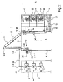
- Fig. 1 is a schematic plan view of an embodiment of the invention Falschdralltexturiermaschine is shown.
- the false twist texturing machine has a machine frame 4.
- the machine frame 4 is formed by a module frame 4.1, a process frame 4.2 and a Aufwickelgestell 4.3, which are firmly connected.
- a separate gate frame 7 is arranged at a distance to the module frame 4.1.
- a plurality of processing points 1.1, 1.2, 1.3, etc. are arranged parallel to each other in the longitudinal direction.
- processing points are preferably provided 218 processing points.
- the first three processing stations are identified by the reference symbols 1.1, 1.2 and 1.3.
- each of the processing stations 1 at least one thread is processed in each case.
- the plurality of processing stations 1 are divided into several processing sections 2. In the embodiment shown in FIG. 1, in each case 12 adjacent processing points 1.1, 1.2, 1.3, etc. form a processing section 2.
- FIG. 1 in each case 12 adjacent processing points 1.1, 1.2, 1.3, etc. form a processing section 2.
- machining sections 2.1 and 2.2 as well as partially the third machining section 2.3 shown
- Each machining section 2.1, 2.2, 2.3, etc. contain several processing units, which are held in a job structure in your machine frame 4, to deduct the threads of the processing section associated threads in parallel from original spools to texturize to stretch and wind up coils.
- Fig. 1 only a portion of the provided in the processing section or in the individual processing stations process units with the reference numerals 10, 11, 12, 13, 16 and 18 are shown schematically.
- the group of deduction delivery plants is marked, each processing point is assigned in each case a deduction delivery, to deduct a thread 38 from a supply spool 8.
- the supply spool 8 is received in the gate frame 7.
- the thread 38 is guided in a processing station, for example, the processing station 1.1 in a false twist zone, which is formed by the Primärloom owned 11, the cooling device 12 and the Falschdralltextkurieraggregat 13. Thereafter, the thread 38 is subjected to a post heat treatment in each of the processing points, which is carried out by the secondary heater 16.
- the thread 38 is wound to a bobbin 21 held on a bobbin holder 46 in the winder 18.
- the winders 18 occupy a width of 3 processing points. Therefore, each of three rewinders - will be discussed later - arranged in a column one above the other in the Aufwickelgestell 4.3.
- a field control unit 42 is assigned to each processing section.
- the field control units 42.1 and 42.2 as well as the field control units (not shown here) of the subsequent processing sections of the false twist texturing machine are coupled to a machine control 43.
- the process units of a processing section can thus be controlled and monitored independently of the processing units of the adjacent processing section.
- the processing sections 2 of the false twist texturing machine each have a specific job structure for processing the threads assigned to the processing section.
- the job structure of the machining section 2.1 will be described with reference to a cross-sectional view of a machining point of this machining section of FIG. 2 and the job structure of the machining section 2.2 with reference to the cross-sectional view of one of the machining points of this machining section of FIG.
- each processing point has a deduction delivery unit 10.
- the deduction delivery plants 10 of the processing section 2.1 are attached to a process module 3.1.
- the process module 3.1 is attached to the module frame 4.1. The design of the process module and the nature of the module frame 4.1 will be explained in more detail below.
- Each of the deduction suppliers is assigned to one of the original coil 8, which are arranged in the gate frame 7.
- each of the feed bobbins 8 is assigned a spare spool 44, wherein the thread end of the spool 8 is knotted to the thread spine of the reserve spool 44.
- the thread 38 is withdrawn via a head thread guide 45 and the thread guides 9.1 and 9.2 through the deduction delivery unit 10.
- the other process units are described in the job description below.
- the primary heater 11 In the thread running direction behind the deduction delivery unit 10 is the elongated primary heater 11, through which the thread 38 is running and is heated to a certain temperature.
- the primary heater 11 could be designed as a high-temperature heater, in which the Schuber vomtemperatur is above 300 ° C.
- the thread 38 in this case would preferably be heated without contact.
- the primary heater 11 is seated in this embodiment, two parallel tracks, so that the threads 38 two adjacent processing points are performed simultaneously by the primary heater 11.
- the cooling device 12 In the thread running direction behind the primary heater 11, the cooling device 12 is provided.
- the primary heater 11 and the cooling device 12 are arranged in this embodiment in a plane behind the other above the module frame 4.1 and the process frame 4.2, wherein between the module frame 4.1 and the process frame 4.2 an operating gear 5 is formed.
- a yarn guide 9.3 In the entrance area of the primary heater 11 is a yarn guide 9.3, which is preferably designed as a deflection roller, arranged so that the thread 38 is guided by the module frame 4.1 in a V-shaped yarn path to the process frame 4.2.
- the job structure could also be designed such that the primary heater 11 and the cooling device 12 are arranged in two roof-shaped mutually lying planes.
- the process frame 4.2 carries in the thread running direction in succession the Falschdralltextkurieraggregat 13, the drafting device 14, the swirling device 40 and the set-delivery 15.
- a false twist drive 26 an electric motor is preferably used, which is also attached to the process rack.
- the thread 38 passes through the swirling device 40.
- the thread 38 is guided into the secondary heating device 16 by the set delivery mechanism 15.
- the secondary heater 16 is for this purpose on the underside of the process frame 4.2 and the Aufwickelgestells 4.3, which are both joined together to form a frame part.
- the secondary heater 16 forms the thread transition from the process frame 4.2 to the winding frame 4.3. As a result, a very compact design is realized.
- the feed delivery plant 17 On the underside of the Aufwickelgestells 4.3 the feed delivery plant 17 is arranged, which immediately deducts the thread 38 from the secondary heater 16 and after deflecting the thread 38 leads to the winding device 18.
- the set delivery mechanism 15 and the feed delivery mechanism 17 are driven at a differential speed such that shrinkage treatment of the thread 38 within the secondary heater 16 is possible.
- the Secondary heater 16 could in this case be formed by a diphyl-heated contact heater.
- the winding device 18- is schematically characterized in this embodiment by a traverse 20, a drive roller 19, a coil holder 46 and a coil 21.
- the winding device 18 also includes a sleeve magazine 22 to perform an automatic bobbin change.
- the auxiliary equipment required for replacing the full bobbins are not shown here.
- a total of three take-up devices 18 of adjacent processing points are arranged one above the other in terms of floor space.
- the winders of the processing section form a machine longitudinal side, over the length of which a Doffgang 6 extends. From the Doffgang 6 let out the full bobbins transport.
- Each delivery mechanism is formed by a godet 23 and an overflow roller 24 associated with the godet 23.
- the godet 23 is driven by a single drive 25.
- the individual drive 25 is preferably formed by an electric motor.
- the overflow roller 24 is freely rotatably mounted, wherein the thread 38 is guided with several wraps on the godet 23 and the overflow roller 24.
- the illustrated in Fig. 2 job structure of the processing section 2.1 has in the processing stations on the process units to draw a submitted thread 38 in a basic process and to texture.
- the thread 38 is withdrawn by the deduction delivery unit 10 of the original spool 8, guided in the false twist zone.
- Falschdralltextkurieraggregat 13 at the end of the false twist zone a false twist is generated in the thread 38, which runs back to the primary heater 11.
- Within the primary heater 11 and the cooling device 12 is a fixing of the conditional by the texturing Crimping in the multifilament yarn 38.
- the yarn 38 is withdrawn from the false twist zone by the draw delivery unit 14 and drawn.
- the stretch delivery unit 14 is driven at a higher speed than the deduction delivery unit 10.
- the thread 38 is wound into a coil 21.
- an operating gear 5 is formed between the module frame 4.1 and the process frame 4.2.
- the process units on the module frame 4.1 and the process units on the process frame 4.2 can advantageously be operated by an operator from the operation gear 5.
- a Doffgang 6 is provided on the longitudinal side of the Aufwickelgestells 4.3.
- FIG. 3.1 a front view of the process module 3.1 and in FIG. 3.2 a rear view of the process module 3.1 are shown.
- FIG. 3.1 a front view of the process module 3.1 and in FIG. 3.2 a rear view of the process module 3.1 are shown.
- the process module 3.1 is mounted replaceably on the module frame 4.1 via a plurality of fastening elements 27.
- the module frame 4.1 in this case has several module slots 47. Overall, three module slots 47.1, 47.2 and 47.3 are formed on the module frame 4.1.
- the process module 3.1 is attached.
- the process module 3.1 of the processing section 2.1 carries the group of deduction delivery plants 10. In Fig. 3.1 and 3.2, three adjacent deduction delivery plants 10.1, 10.2 and 10.3 are shown. Each of the delivery units 10.1, 10.2 and 10.3 is driven by a single drive 25.1, 25.2 and 25.3. Thus drives the single drive 25.1 the deduction delivery 10.1 and the single drive 25.2 the deduction delivery 10.2.
- Each of the deduction delivery 10.1, 10.2, 10.3, etc. of the processing points pulls a thread 38 from a supply spool on the yarn guide 9.1.
- all individual drives 25 of the deduction delivery units 10 are connected to an electrical distributor 48.
- the electrical distributor 48 has a plurality of plug connections 49. Via the plug connections 49 and the electrical distributor 48, the electrical connection of the individual drives 25 of the delivery units 10 takes place.
- the individual drives 25 are preferably controlled via a group converter.
- the group converter could either be part of the electrical distributor 48 or be arranged externally in an electronic assembly assigned to the machining sections 2.1.
- the job structure of the adjacent machining section 2.2 of the embodiment is shown by a cross section of a machining point of the machining section 2.2 in FIG.
- the job structure of the processing station 2.2 is substantially identical to the job structure of the processing station 2.1, so that reference is made at this point to the previous description and then only the differences in job structure will be described. Because of the overview, the components of the same function have been identified with identical reference numerals.
- the process module 3.1 carries the deduction delivery units 10 of the processing points of the processing section 2.2.
- the construction of the process module 3.1 is identical to the process module arranged in the adjacent processing section 2.1. In that regard, reference is made to the preceding description.
- a delivery mechanism 29 and a delivery point 36 are arranged per processing point.
- a supply reel 37 is held in each processing station, on which an additional thread 39 is presented.
- the additional thread 39 is subtracted by the delivery mechanism 29 to the process module 3.2 and above the operating 5 arranged deflection rollers 41.1 and 41.2 supplied to the stretch delivery 14.
- the additional thread and the thread 38 are brought together to form a composite thread.
- the job structure of the processing section 2.2 thus contains additional processing units, - to produce in each case a composite thread in the associated processing points of the processing section 2.2.
- an additional thread z. B. an elastane thread the crimped thread are attached.
- the thread 38 is withdrawn in each of the processing points of the machining section 2.2 and fed to the false twist zone by the deduction mechanism 10.
- the additional thread 39 is withdrawn by the delivery mechanism 29 from the original spool 37 via a yarn guide 35 attached to the process module 3.2 in each of the processing points.
- the supply spool 37 is arranged at the initial position 36 on the process module 3.2.
- the additional thread 39 is passed over deflection rollers 41.1 and 41.2 at the false twist zone directly to the stretch delivery unit 14. After texturing and stretching of the thread 38 of the thread 38 and the additional thread 39 is connected in the swirling device 40.
- the resulting composite thread is wound up after a heat treatment in the secondary heater 16 to form a coil 21.
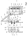
- the inlet area of the processing section 2.2 is shown schematically in different views for a more detailed explanation of the process modules 3.1 and 3.2 in Figures 5.1 and 5.2.
- Fig. 5.1 shows a detail in a front view of the operation gear 5 out
- Fig. 5.2 shows a section of the back of the module frame 4.1.
- the module frame 4.1 is occupied in the processing section 2.2 in the module slots 47.1 and 47.2, each with the process module 3.1 and 3.2.
- the process module 3.1 in the processing section 2.2 is identical to the process module 2.1 in the processing section 2.1. In that regard, reference is made to the preceding description.
- the process module 3.2 carries the group of delivery mechanisms 29 of the processing section 2.2.
- Fig. 5.1 the first three delivery mechanisms 29.1, 29.2, 29.3 of the groups are shown.
- Each of the delivery mechanisms 29 is formed by a driven godet 31 and an overrun roller 30.
- the godet 31 is driven by a single drive 33, wherein the individual drives 33.1, 33.2 and 33.3 of the first three delivery mechanisms 29.1, 29.3 and 29.3 are shown.
- the process module 3.2 also has an electrical distributor 48, which is coupled to the individual drives 33 of the delivery mechanisms 29.
- the electrical distributor 48 is connected via the plug connections 49 to an external power supply and control device.
- a feed point 36 which is provided for receiving a feed bobbin 37, is provided below the delivery mechanisms 29 for each processing point of the processing section 2.2.
- a thread guide 35 is arranged on the process module 3.2 per processing point.
- the following processing sections of the embodiment may each have a job structure corresponding to the job structure of the machining section 2.1 of FIG. 2 or the job structure of the machining section 2.2 of FIG.
- at least one of the processing stations of the embodiment has a third different job structure for producing a further yarn type.
- false twist texturing machines are operated with few different spot structures in the processing sections.
- the location structures of the processing sections are substantially changed by additional process units, which are arranged substantially in the inlet region of the machine.
- all processing units arranged within the job structure are suitable for generating changes in the job structure.
- the job structure of the processing section 2.1 of the embodiment could be changed by the fact that the secondary heater 16 is not operated, so that a false twist-textured thread is wound into a coil without a post-heat treatment.
- a primary heater 11 in a processing section which is designed as a non-contact heater and to use a contact keyer as a primary heater 11 in an adjacent processing section.
- the invention is not limited to the fact that the process module are arranged exclusively in a module frame placed in the inlet region.
- the process rack is suitable for accommodating one or more process modules with one or more groups of processing units as a module rack.
- a process module which is constructed correspondingly in the process module 3.1, could be arranged between the swirling device 40 and the draft delivery device 14. This would precede an additional delivery mechanism of the swirling device 40, so that a separate adjustment of the tension for swirling the thread or threads is possible.
- FIG. 6 shows further exemplary embodiments of process modules 3, such as could be used, for example, in one of the processing sections.
- the embodiment of the process module 3 shown in FIG. 3.1 is particularly suitable for producing a composite thread.
- the delivery unit 10 and the delivery mechanism 29 are mounted together on the process module 3.
- FIG. 6.1 shows the structure of the process module 3 of a processing station.
- the delivery mechanism 29 is at the process module 3, the reference point 36 and the Thread guide 35 assigned.
- a document spool 37 is held.
- the deduction delivery unit 10 and the delivery mechanism 29 on the process module 3 are preferably arranged in different thread running planes to guide two parallel threads without additional deflection in the processing site.
- FIG. 6.2 shows a further exemplary embodiment of a process module 3, in which the process module 3 has the trigger delivery unit and a further delivery mechanism 29. Both delivery mechanisms are each formed by an overflow roller and a godet. Between the delivery mechanisms 10 and 29, a swirling device 40 is held on the process module. The swirling device 40 is connected to a compressed air source (not shown here), so that the thread 38 routed through a thread channel is swirled by a stream of compressed air. This pre-treatment of the thread 38 preceding the false twist crimp leads to an improvement in the bulkiness of the thread in the crimped state.
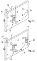
- FIG. 7 shows a further exemplary embodiment of a process module 3 schematically in a section for a processing station.
- the process module 3 is shown here in a first configuration in FIG. 7.1 and in a second configuration in FIG. 7.2.
- the deduction delivery unit 10 already described above is arranged.
- the deduction delivery 10 are associated with a plurality of receiving device 28, through which the inclusion of additional process units is possible.
- the process module 3 is described without additional processing units held in the receiving devices 28.
- the receiving devices of the process module 3 are occupied by an additional delivery mechanism 29 and a draw pin 34.
- a thread 38 from a document coil.
- the thread 38 is guided into a first draw zone, which extends between the deduction delivery unit 10 and the delivery mechanism 29.
- a heated draw pin 34 is arranged within the draw zone.
- the draw pin 34 could in this case be heated to a surface temperature in the range from 80.degree. C. to 160.degree.
- the draw pin 34 is looped by the thread 38 and withdrawn from the delivery mechanism 29.
- the draw pin 34 could be assigned to a thread guide on the process module 3, which would be variable in its position to set a certain angle of wrap on the draw pin 34. From the delivery mechanism 29, the thus pre-stretched thread 38 is guided into the false twist texturing zone.
- the further yarn path could correspond to the job structure of the processing section 2.1 of the embodiment described.
Landscapes
- Engineering & Computer Science (AREA)
- Mechanical Engineering (AREA)
- Textile Engineering (AREA)
- Yarns And Mechanical Finishing Of Yarns Or Ropes (AREA)
Claims (12)
- Machine de texturation par fausse torsion pour texturer par fausse torsion une multiplicité de fils synthétiques avec une pluralité de postes de traitement (1) divisés en sections de traitement (2), chacune des sections de traitement (2.1, 2.2) ayant un montage de postes avec une pluralité d'agrégats de processus (10, 11, 12, 13, 14, 15, 18) retenus sur un bâti de machine (4) pour retirer parallèlement des bobines d'alimentation (8) les fils associés à la section de traitement (2.1, 2.2), les texturer, les étirer et les enrouler en bobines (21), caractérisée en ce que les montages de postes des sections de traitement (2.1, 2.2) sont réalisés différemment quant à leur nombre et/ou à leur genre d'agrégats de processus (10, 11, 12, 13, 14, 15, 18).
- Machine de texturation par fausse torsion selon la revendication 1, caractérisée en ce qu'une partie des agrégats de processus (10) sont retenus à l'intérieur des montages de postes des sections de traitement (2.1, 2.2) par des modules de processus (3) et en ce que les modules de processus (3) sont fixés de manière échangeable sur une partie du bâti de machine (4) réalisée comme bâti de module (4.1).
- Machine de texturation par fausse torsion selon la revendication 2, caractérisée en ce que le bâti de module (4.1) peut être équipé au choix dans chaque section de traitement d'un module de processus ou d'une pluralité de modules de processus (3.1, 3.2), dans quel cas chacun des modules de processus (3.1, 3.2) porte au moins un groupe d'agrégats de processus (10,29).
- Machine de texturation par fausse torsion selon la revendication 2 ou 3, caractérisée en ce que les modules de processus (3) ont respectivement un distributeur électrique (48) qui est relié aux agrégats de processus (10) du module de processus (3.1) et qui a des prises embrochables (49) pour le raccordement électrique des agrégats de processus (10).
- Machine de texturation par fausse torsion selon la revendication 4, caractérisée en ce qu'un entraînement individuel (25) agencé sur le module de processus (3.1) est associé à chaque agrégat de processus (10) entraînable sur le module de processus (3.1) et en ce que les entraînements individuels (25) sont reliés au distributeur électrique (48).
- Machine de texturation par fausse torsion selon l'une des revendications 2 à 5, caractérisée en ce que le bâti de module (4.1) est agencé dans une région d'entrée de la machine et porte à l'intérieur des montages de postes des sections de traitement (2.1, 2.2) les modules de processus (3.1, 3.2) avec les groupes des dispositifs d'alimentation de retirage (10), lesquels dispositifs d'alimentation de retirage (10) retirent les fils (38) des bobines d'alimentation (8) agencées dans un bâti de cantre.
- Machine de texturation par fausse torsion selon la revendication 6, caractérisée en ce que les modules de processus (3.1) sont équipés au choix de groupes d'agrégats de processus, qui sont formés par des dispositifs d'alimentation, des tiges d'étirage, des dispositifs à tourbillonnement et/ou des positions d'alimentation de bobines.
- Machine de texturation par fausse torsion selon la revendication 6 ou 7, caractérisée en ce que les modules de processus (3) de chaque poste de traitement ont au moins un dispositif de réception (28) par lequel on peut intégrer au choix un agrégat de processus supplémentaire (29) sur le module de processus (3) à l'intérieur du poste de traitement.
- Machine de texturation par fausse torsion selon la revendication 8, caractérisée en ce que le bâti de module (4.1) forme un couloir de service (5) avec un bâti de processus (4.2) opposé, le bâti de processus (4.2) portant au moins une partie des agrégats de processus (13, 14), de sorte que les modules de processus sur le bâti de module et les agrégats de processus sur le bâti de processus peuvent être opérés du couloir de service.
- Machine de texturation par fausse torsion selon la revendication 9, caractérisée en ce que le transfert du fil dans le montage des postes des sections de traitement depuis le bâti de module jusqu'au bâti de processus est formé par un dispositif de chauffage et un dispositif de refroidissement qui sont agencés de manière telle au dessus du couloir de service que le fil est guidé dans le poste de traitement depuis un dispositif d'alimentation de retirage jusqu'à un agrégat de fausse torsion en un trajet de fil sensiblement en forme de V.
- Machine de texturation par fausse torsion selon l'une des revendications 9 ou 10, caractérisée en ce qu'une partie du bâti de machine, réalisée en tant que bâti d'enroulement est prévue pour recevoir des dispositifs d'enroulement et en ce que le bâti de processus et le bâti d'enroulement sont assemblés de telle manière en une pièce de bâti commune que le fil est guidé dans le poste de traitement depuis un agrégat de fausse torsion jusqu'au dispositif d'enroulement en un trajet de fil sensiblement en forme de U.
- Machine de texturation par fausse torsion selon l'une des revendications précédentes, caractérisée en ce que les agrégats de processus formant le montage des postes d'une des sections de traitement, sont commandés et surveillés indépendamment des agrégats de processus de la section de traitement adjacente.
Applications Claiming Priority (3)
| Application Number | Priority Date | Filing Date | Title |
|---|---|---|---|
| DE2002132547 DE10232547A1 (de) | 2002-07-18 | 2002-07-18 | Falschdralltexturiermaschine |
| DE10232547 | 2002-07-18 | ||
| PCT/EP2003/006982 WO2004009886A1 (fr) | 2002-07-18 | 2003-07-01 | Machine de texturation par fausse torsion |
Publications (2)
| Publication Number | Publication Date |
|---|---|
| EP1523592A1 EP1523592A1 (fr) | 2005-04-20 |
| EP1523592B1 true EP1523592B1 (fr) | 2007-02-28 |
Family
ID=30010142
Family Applications (1)
| Application Number | Title | Priority Date | Filing Date |
|---|---|---|---|
| EP03764930A Expired - Lifetime EP1523592B1 (fr) | 2002-07-18 | 2003-07-01 | Machine de texturation par fausse torsion |
Country Status (8)
| Country | Link |
|---|---|
| EP (1) | EP1523592B1 (fr) |
| JP (1) | JP4422615B2 (fr) |
| CN (1) | CN100420778C (fr) |
| AU (1) | AU2003249917A1 (fr) |
| DE (2) | DE10232547A1 (fr) |
| ES (1) | ES2282677T3 (fr) |
| TW (1) | TWI299762B (fr) |
| WO (1) | WO2004009886A1 (fr) |
Families Citing this family (9)
| Publication number | Priority date | Publication date | Assignee | Title |
|---|---|---|---|---|
| EP1566474A3 (fr) * | 2004-02-20 | 2006-04-19 | Barmag Spinnzwirn GmbH | Machine à texturer par jet d'air |
| EP1838908B1 (fr) * | 2004-12-22 | 2012-07-18 | Oerlikon Textile GmbH & Co. KG | Procede et dispositif pour filage par fusion et texturation d'une pluralite de fils multifilaments |
| CH701660B1 (de) | 2009-08-25 | 2013-08-30 | Oerlikon Textile Gmbh & Co Kg | Falschdralltexturiermaschine. |
| CN102383229A (zh) * | 2010-08-31 | 2012-03-21 | 欧瑞康纺织有限及两合公司 | 纺织机 |
| CN102485988A (zh) * | 2010-12-02 | 2012-06-06 | 欧瑞康(中国)科技有限公司 | 变形机 |
| JP6203853B2 (ja) * | 2013-09-13 | 2017-09-27 | 富士機械製造株式会社 | 機械工作システム |
| CN105683430B (zh) * | 2013-11-02 | 2018-08-14 | 欧瑞康纺织有限及两合公司 | 变形机 |
| DE102014014729A1 (de) | 2013-11-15 | 2015-05-21 | Oerlikon Textile Gmbh & Co. Kg | Texturiermaschine |
| CN105986343B (zh) * | 2015-02-12 | 2020-12-01 | 欧瑞康纺织有限及两合公司 | 变形机 |
Family Cites Families (8)
| Publication number | Priority date | Publication date | Assignee | Title |
|---|---|---|---|---|
| DE3324243A1 (de) * | 1982-07-09 | 1984-02-16 | Barmag Barmer Maschinenfabrik Ag, 5630 Remscheid | Falschzwirnkraeuselmaschine und verfahren zur ueberbrueckung kurzzeitiger spannun gsausfaelle an textilmaschinen |
| DE3623370A1 (de) * | 1985-07-13 | 1987-01-29 | Barmag Barmer Maschf | Texturiermaschine |
| DE3889576D1 (de) * | 1987-04-02 | 1994-06-23 | Barmag Barmer Maschf | Lufttexturiermaschine. |
| DE3910181A1 (de) * | 1989-03-29 | 1990-10-04 | Rieter Ag Maschf | Steuersystem fuer eine textilmaschine |
| DE3928831A1 (de) * | 1989-08-31 | 1991-03-07 | Schlafhorst & Co W | Vielstellen-textilmaschine und verfahren zum vorbereiten des betriebs der textilmaschine |
| CN1045320C (zh) * | 1992-10-08 | 1999-09-29 | 巴马格股份公司 | 假捻卷曲机 |
| TW340533U (en) * | 1993-09-04 | 1998-09-11 | Barmag Barmer Maschf | False twist crimping machine |
| DE10026942A1 (de) * | 2000-05-30 | 2001-12-06 | Barmag Barmer Maschf | Verfahren zur Steuerung einer Texturiermaschine sowie eine Texturiermaschine |
-
2002
- 2002-07-18 DE DE2002132547 patent/DE10232547A1/de not_active Withdrawn
-
2003
- 2003-06-25 TW TW92117276A patent/TWI299762B/zh not_active IP Right Cessation
- 2003-07-01 AU AU2003249917A patent/AU2003249917A1/en not_active Abandoned
- 2003-07-01 WO PCT/EP2003/006982 patent/WO2004009886A1/fr active IP Right Grant
- 2003-07-01 ES ES03764930T patent/ES2282677T3/es not_active Expired - Lifetime
- 2003-07-01 EP EP03764930A patent/EP1523592B1/fr not_active Expired - Lifetime
- 2003-07-01 DE DE50306674T patent/DE50306674D1/de not_active Expired - Fee Related
- 2003-07-01 JP JP2004522197A patent/JP4422615B2/ja not_active Expired - Fee Related
- 2003-07-01 CN CNB038169614A patent/CN100420778C/zh not_active Expired - Fee Related
Also Published As
| Publication number | Publication date |
|---|---|
| DE50306674D1 (de) | 2007-04-12 |
| CN100420778C (zh) | 2008-09-24 |
| WO2004009886A1 (fr) | 2004-01-29 |
| AU2003249917A1 (en) | 2004-02-09 |
| DE10232547A1 (de) | 2004-02-05 |
| TW200401856A (en) | 2004-02-01 |
| JP2005533196A (ja) | 2005-11-04 |
| EP1523592A1 (fr) | 2005-04-20 |
| JP4422615B2 (ja) | 2010-02-24 |
| CN1668791A (zh) | 2005-09-14 |
| ES2282677T3 (es) | 2007-10-16 |
| TWI299762B (en) | 2008-08-11 |
Similar Documents
| Publication | Publication Date | Title |
|---|---|---|
| EP1527217B1 (fr) | Dispositif de filage et d'enroulement | |
| EP1594785B1 (fr) | Dispositif pour fabriquer et enrouler des fils synthetiques | |
| EP2007935B1 (fr) | Procede et dispositif d'extraction et d'etirage d'un fil multifilament | |
| EP3036361B1 (fr) | Dispositif permettant de filer une pluralité de fils synthetiques | |
| EP2145848B1 (fr) | Machine de texturation à fausse torsion | |
| EP1238273A2 (fr) | Procede pour commander une machine a texturer, et machine a texturer | |
| EP1523592B1 (fr) | Machine de texturation par fausse torsion | |
| EP2347045B1 (fr) | Dispositif de chauffage | |
| DE102013109530A1 (de) | Textilmaschine | |
| DE3623370A1 (de) | Texturiermaschine | |
| CH701660A2 (de) | Falschdralltexturiermaschine. | |
| EP1446521B1 (fr) | Machine a texturer | |
| EP1409777B1 (fr) | Machine de texturation a fausse torsion | |
| WO2006069642A1 (fr) | Procede et dispositif pour filage par fusion et texturation d'une pluralite de fils multifilaments | |
| EP0284945B1 (fr) | Machine à texturer par jet d'air | |
| WO2014139976A1 (fr) | Dispositif de filage à chaud, d'étirage et d'enroulement de plusieurs fils synthétiques | |
| EP1425450B1 (fr) | Machine a texturer a fausse torsion | |
| WO2019030134A1 (fr) | Dispositif pour retirer et enrouler une nappe de fils | |
| EP1584717A1 (fr) | Machine de traitement de fil | |
| EP1566474A2 (fr) | Machine à texturer par jet d'air | |
| WO2014170185A1 (fr) | Machine de texturation | |
| WO2022208199A1 (fr) | Installation de fabrication de fil | |
| EP1904673A2 (fr) | Machine a texturer | |
| DE102004025496A1 (de) | Falschdralltexturiermaschine |
Legal Events
| Date | Code | Title | Description |
|---|---|---|---|
| PUAI | Public reference made under article 153(3) epc to a published international application that has entered the european phase |
Free format text: ORIGINAL CODE: 0009012 |
|
| 17P | Request for examination filed |
Effective date: 20050114 |
|
| AK | Designated contracting states |
Kind code of ref document: A1 Designated state(s): AT BE BG CH CY CZ DE DK EE ES FI FR GB GR HU IE IT LI LU MC NL PT RO SE SI SK TR |
|
| AX | Request for extension of the european patent |
Extension state: AL LT LV MK |
|
| DAX | Request for extension of the european patent (deleted) | ||
| RBV | Designated contracting states (corrected) |
Designated state(s): CH DE ES FR IT LI TR |
|
| GRAP | Despatch of communication of intention to grant a patent |
Free format text: ORIGINAL CODE: EPIDOSNIGR1 |
|
| RIN1 | Information on inventor provided before grant (corrected) |
Inventor name: TOENS, ANDREAS Inventor name: PYRA, MICHAEL Inventor name: WORTMANN, THOMAS Inventor name: ZENKER, DIETER |
|
| GRAS | Grant fee paid |
Free format text: ORIGINAL CODE: EPIDOSNIGR3 |
|
| GRAA | (expected) grant |
Free format text: ORIGINAL CODE: 0009210 |
|
| AK | Designated contracting states |
Kind code of ref document: B1 Designated state(s): CH DE ES FR IT LI TR |
|
| REG | Reference to a national code |
Ref country code: CH Ref legal event code: EP |
|
| REF | Corresponds to: |
Ref document number: 50306674 Country of ref document: DE Date of ref document: 20070412 Kind code of ref document: P |
|
| RAP2 | Party data changed (patent owner data changed or rights of a patent transferred) |
Owner name: OERLIKON TEXTILE GMBH & CO. KG |
|
| REG | Reference to a national code |
Ref country code: ES Ref legal event code: FG2A Ref document number: 2282677 Country of ref document: ES Kind code of ref document: T3 |
|
| PLBE | No opposition filed within time limit |
Free format text: ORIGINAL CODE: 0009261 |
|
| STAA | Information on the status of an ep patent application or granted ep patent |
Free format text: STATUS: NO OPPOSITION FILED WITHIN TIME LIMIT |
|
| 26N | No opposition filed |
Effective date: 20071129 |
|
| PGFP | Annual fee paid to national office [announced via postgrant information from national office to epo] |
Ref country code: DE Payment date: 20080729 Year of fee payment: 6 Ref country code: ES Payment date: 20080717 Year of fee payment: 6 |
|
| PGFP | Annual fee paid to national office [announced via postgrant information from national office to epo] |
Ref country code: FR Payment date: 20080722 Year of fee payment: 6 |
|
| PGFP | Annual fee paid to national office [announced via postgrant information from national office to epo] |
Ref country code: CH Payment date: 20090728 Year of fee payment: 7 Ref country code: TR Payment date: 20090701 Year of fee payment: 7 |
|
| REG | Reference to a national code |
Ref country code: FR Ref legal event code: ST Effective date: 20100331 |
|
| PG25 | Lapsed in a contracting state [announced via postgrant information from national office to epo] |
Ref country code: FR Free format text: LAPSE BECAUSE OF NON-PAYMENT OF DUE FEES Effective date: 20090731 |
|
| PGFP | Annual fee paid to national office [announced via postgrant information from national office to epo] |
Ref country code: IT Payment date: 20090723 Year of fee payment: 7 |
|
| PG25 | Lapsed in a contracting state [announced via postgrant information from national office to epo] |
Ref country code: DE Free format text: LAPSE BECAUSE OF NON-PAYMENT OF DUE FEES Effective date: 20100202 |
|
| REG | Reference to a national code |
Ref country code: ES Ref legal event code: FD2A Effective date: 20090702 |
|
| PG25 | Lapsed in a contracting state [announced via postgrant information from national office to epo] |
Ref country code: ES Free format text: LAPSE BECAUSE OF NON-PAYMENT OF DUE FEES Effective date: 20090702 |
|
| REG | Reference to a national code |
Ref country code: CH Ref legal event code: PL |
|
| PG25 | Lapsed in a contracting state [announced via postgrant information from national office to epo] |
Ref country code: CH Free format text: LAPSE BECAUSE OF NON-PAYMENT OF DUE FEES Effective date: 20100731 Ref country code: LI Free format text: LAPSE BECAUSE OF NON-PAYMENT OF DUE FEES Effective date: 20100731 |
|
| PG25 | Lapsed in a contracting state [announced via postgrant information from national office to epo] |
Ref country code: IT Free format text: LAPSE BECAUSE OF NON-PAYMENT OF DUE FEES Effective date: 20100701 |
|
| PG25 | Lapsed in a contracting state [announced via postgrant information from national office to epo] |
Ref country code: TR Free format text: LAPSE BECAUSE OF NON-PAYMENT OF DUE FEES Effective date: 20100701 |