EP1523403B1 - Extrudeuse - Google Patents
Extrudeuse Download PDFInfo
- Publication number
- EP1523403B1 EP1523403B1 EP03730036.5A EP03730036A EP1523403B1 EP 1523403 B1 EP1523403 B1 EP 1523403B1 EP 03730036 A EP03730036 A EP 03730036A EP 1523403 B1 EP1523403 B1 EP 1523403B1
- Authority
- EP
- European Patent Office
- Prior art keywords
- screw
- sections
- extruder
- annular sections
- screw element
- Prior art date
- Legal status (The legal status is an assumption and is not a legal conclusion. Google has not performed a legal analysis and makes no representation as to the accuracy of the status listed.)
- Expired - Lifetime
Links
- 239000000126 substance Substances 0.000 claims description 8
- 239000000463 material Substances 0.000 description 9
- 238000004898 kneading Methods 0.000 description 3
- 238000007789 sealing Methods 0.000 description 3
- 238000000034 method Methods 0.000 description 2
- 230000007935 neutral effect Effects 0.000 description 2
- 238000010008 shearing Methods 0.000 description 2
- 230000000694 effects Effects 0.000 description 1
- 238000005516 engineering process Methods 0.000 description 1
- 239000004744 fabric Substances 0.000 description 1
- 230000009969 flowable effect Effects 0.000 description 1
- 238000010438 heat treatment Methods 0.000 description 1
- 230000002045 lasting effect Effects 0.000 description 1
- 239000007788 liquid Substances 0.000 description 1
- 230000001737 promoting effect Effects 0.000 description 1
- 230000007704 transition Effects 0.000 description 1
- -1 viscous Substances 0.000 description 1
Images


Classifications
-
- B—PERFORMING OPERATIONS; TRANSPORTING
- B29—WORKING OF PLASTICS; WORKING OF SUBSTANCES IN A PLASTIC STATE IN GENERAL
- B29B—PREPARATION OR PRETREATMENT OF THE MATERIAL TO BE SHAPED; MAKING GRANULES OR PREFORMS; RECOVERY OF PLASTICS OR OTHER CONSTITUENTS OF WASTE MATERIAL CONTAINING PLASTICS
- B29B7/00—Mixing; Kneading
- B29B7/30—Mixing; Kneading continuous, with mechanical mixing or kneading devices
- B29B7/34—Mixing; Kneading continuous, with mechanical mixing or kneading devices with movable mixing or kneading devices
- B29B7/38—Mixing; Kneading continuous, with mechanical mixing or kneading devices with movable mixing or kneading devices rotary
- B29B7/46—Mixing; Kneading continuous, with mechanical mixing or kneading devices with movable mixing or kneading devices rotary with more than one shaft
- B29B7/48—Mixing; Kneading continuous, with mechanical mixing or kneading devices with movable mixing or kneading devices rotary with more than one shaft with intermeshing devices, e.g. screws
- B29B7/481—Mixing; Kneading continuous, with mechanical mixing or kneading devices with movable mixing or kneading devices rotary with more than one shaft with intermeshing devices, e.g. screws provided with paddles, gears or discs
-
- B—PERFORMING OPERATIONS; TRANSPORTING
- B29—WORKING OF PLASTICS; WORKING OF SUBSTANCES IN A PLASTIC STATE IN GENERAL
- B29B—PREPARATION OR PRETREATMENT OF THE MATERIAL TO BE SHAPED; MAKING GRANULES OR PREFORMS; RECOVERY OF PLASTICS OR OTHER CONSTITUENTS OF WASTE MATERIAL CONTAINING PLASTICS
- B29B7/00—Mixing; Kneading
- B29B7/30—Mixing; Kneading continuous, with mechanical mixing or kneading devices
- B29B7/34—Mixing; Kneading continuous, with mechanical mixing or kneading devices with movable mixing or kneading devices
- B29B7/38—Mixing; Kneading continuous, with mechanical mixing or kneading devices with movable mixing or kneading devices rotary
- B29B7/46—Mixing; Kneading continuous, with mechanical mixing or kneading devices with movable mixing or kneading devices rotary with more than one shaft
- B29B7/48—Mixing; Kneading continuous, with mechanical mixing or kneading devices with movable mixing or kneading devices rotary with more than one shaft with intermeshing devices, e.g. screws
- B29B7/482—Mixing; Kneading continuous, with mechanical mixing or kneading devices with movable mixing or kneading devices rotary with more than one shaft with intermeshing devices, e.g. screws provided with screw parts in addition to other mixing parts, e.g. paddles, gears, discs
- B29B7/483—Mixing; Kneading continuous, with mechanical mixing or kneading devices with movable mixing or kneading devices rotary with more than one shaft with intermeshing devices, e.g. screws provided with screw parts in addition to other mixing parts, e.g. paddles, gears, discs the other mixing parts being discs perpendicular to the screw axis
-
- B—PERFORMING OPERATIONS; TRANSPORTING
- B29—WORKING OF PLASTICS; WORKING OF SUBSTANCES IN A PLASTIC STATE IN GENERAL
- B29B—PREPARATION OR PRETREATMENT OF THE MATERIAL TO BE SHAPED; MAKING GRANULES OR PREFORMS; RECOVERY OF PLASTICS OR OTHER CONSTITUENTS OF WASTE MATERIAL CONTAINING PLASTICS
- B29B7/00—Mixing; Kneading
- B29B7/30—Mixing; Kneading continuous, with mechanical mixing or kneading devices
- B29B7/34—Mixing; Kneading continuous, with mechanical mixing or kneading devices with movable mixing or kneading devices
- B29B7/38—Mixing; Kneading continuous, with mechanical mixing or kneading devices with movable mixing or kneading devices rotary
- B29B7/46—Mixing; Kneading continuous, with mechanical mixing or kneading devices with movable mixing or kneading devices rotary with more than one shaft
- B29B7/48—Mixing; Kneading continuous, with mechanical mixing or kneading devices with movable mixing or kneading devices rotary with more than one shaft with intermeshing devices, e.g. screws
- B29B7/488—Parts, e.g. casings, sealings; Accessories, e.g. flow controlling or throttling devices
- B29B7/489—Screws
-
- B—PERFORMING OPERATIONS; TRANSPORTING
- B29—WORKING OF PLASTICS; WORKING OF SUBSTANCES IN A PLASTIC STATE IN GENERAL
- B29C—SHAPING OR JOINING OF PLASTICS; SHAPING OF MATERIAL IN A PLASTIC STATE, NOT OTHERWISE PROVIDED FOR; AFTER-TREATMENT OF THE SHAPED PRODUCTS, e.g. REPAIRING
- B29C48/00—Extrusion moulding, i.e. expressing the moulding material through a die or nozzle which imparts the desired form; Apparatus therefor
- B29C48/25—Component parts, details or accessories; Auxiliary operations
- B29C48/251—Design of extruder parts, e.g. by modelling based on mathematical theories or experiments
- B29C48/2517—Design of extruder parts, e.g. by modelling based on mathematical theories or experiments of intermeshing screws
-
- B—PERFORMING OPERATIONS; TRANSPORTING
- B29—WORKING OF PLASTICS; WORKING OF SUBSTANCES IN A PLASTIC STATE IN GENERAL
- B29C—SHAPING OR JOINING OF PLASTICS; SHAPING OF MATERIAL IN A PLASTIC STATE, NOT OTHERWISE PROVIDED FOR; AFTER-TREATMENT OF THE SHAPED PRODUCTS, e.g. REPAIRING
- B29C48/00—Extrusion moulding, i.e. expressing the moulding material through a die or nozzle which imparts the desired form; Apparatus therefor
- B29C48/25—Component parts, details or accessories; Auxiliary operations
- B29C48/256—Exchangeable extruder parts
- B29C48/2564—Screw parts
-
- B—PERFORMING OPERATIONS; TRANSPORTING
- B29—WORKING OF PLASTICS; WORKING OF SUBSTANCES IN A PLASTIC STATE IN GENERAL
- B29C—SHAPING OR JOINING OF PLASTICS; SHAPING OF MATERIAL IN A PLASTIC STATE, NOT OTHERWISE PROVIDED FOR; AFTER-TREATMENT OF THE SHAPED PRODUCTS, e.g. REPAIRING
- B29C48/00—Extrusion moulding, i.e. expressing the moulding material through a die or nozzle which imparts the desired form; Apparatus therefor
- B29C48/25—Component parts, details or accessories; Auxiliary operations
- B29C48/36—Means for plasticising or homogenising the moulding material or forcing it through the nozzle or die
- B29C48/395—Means for plasticising or homogenising the moulding material or forcing it through the nozzle or die using screws surrounded by a cooperating barrel, e.g. single screw extruders
- B29C48/40—Means for plasticising or homogenising the moulding material or forcing it through the nozzle or die using screws surrounded by a cooperating barrel, e.g. single screw extruders using two or more parallel screws or at least two parallel non-intermeshing screws, e.g. twin screw extruders
- B29C48/402—Means for plasticising or homogenising the moulding material or forcing it through the nozzle or die using screws surrounded by a cooperating barrel, e.g. single screw extruders using two or more parallel screws or at least two parallel non-intermeshing screws, e.g. twin screw extruders the screws having intermeshing parts
-
- B—PERFORMING OPERATIONS; TRANSPORTING
- B29—WORKING OF PLASTICS; WORKING OF SUBSTANCES IN A PLASTIC STATE IN GENERAL
- B29C—SHAPING OR JOINING OF PLASTICS; SHAPING OF MATERIAL IN A PLASTIC STATE, NOT OTHERWISE PROVIDED FOR; AFTER-TREATMENT OF THE SHAPED PRODUCTS, e.g. REPAIRING
- B29C48/00—Extrusion moulding, i.e. expressing the moulding material through a die or nozzle which imparts the desired form; Apparatus therefor
- B29C48/25—Component parts, details or accessories; Auxiliary operations
- B29C48/36—Means for plasticising or homogenising the moulding material or forcing it through the nozzle or die
- B29C48/395—Means for plasticising or homogenising the moulding material or forcing it through the nozzle or die using screws surrounded by a cooperating barrel, e.g. single screw extruders
- B29C48/40—Means for plasticising or homogenising the moulding material or forcing it through the nozzle or die using screws surrounded by a cooperating barrel, e.g. single screw extruders using two or more parallel screws or at least two parallel non-intermeshing screws, e.g. twin screw extruders
- B29C48/405—Intermeshing co-rotating screws
-
- B—PERFORMING OPERATIONS; TRANSPORTING
- B29—WORKING OF PLASTICS; WORKING OF SUBSTANCES IN A PLASTIC STATE IN GENERAL
- B29C—SHAPING OR JOINING OF PLASTICS; SHAPING OF MATERIAL IN A PLASTIC STATE, NOT OTHERWISE PROVIDED FOR; AFTER-TREATMENT OF THE SHAPED PRODUCTS, e.g. REPAIRING
- B29C48/00—Extrusion moulding, i.e. expressing the moulding material through a die or nozzle which imparts the desired form; Apparatus therefor
- B29C48/25—Component parts, details or accessories; Auxiliary operations
- B29C48/36—Means for plasticising or homogenising the moulding material or forcing it through the nozzle or die
- B29C48/50—Details of extruders
- B29C48/505—Screws
- B29C48/57—Screws provided with kneading disc-like elements, e.g. with oval-shaped elements
-
- B—PERFORMING OPERATIONS; TRANSPORTING
- B29—WORKING OF PLASTICS; WORKING OF SUBSTANCES IN A PLASTIC STATE IN GENERAL
- B29C—SHAPING OR JOINING OF PLASTICS; SHAPING OF MATERIAL IN A PLASTIC STATE, NOT OTHERWISE PROVIDED FOR; AFTER-TREATMENT OF THE SHAPED PRODUCTS, e.g. REPAIRING
- B29C48/00—Extrusion moulding, i.e. expressing the moulding material through a die or nozzle which imparts the desired form; Apparatus therefor
- B29C48/25—Component parts, details or accessories; Auxiliary operations
- B29C48/36—Means for plasticising or homogenising the moulding material or forcing it through the nozzle or die
- B29C48/50—Details of extruders
- B29C48/505—Screws
- B29C48/575—Screws provided with elements of a generally circular cross-section for shearing the melt, i.e. shear-ring elements
-
- B—PERFORMING OPERATIONS; TRANSPORTING
- B29—WORKING OF PLASTICS; WORKING OF SUBSTANCES IN A PLASTIC STATE IN GENERAL
- B29C—SHAPING OR JOINING OF PLASTICS; SHAPING OF MATERIAL IN A PLASTIC STATE, NOT OTHERWISE PROVIDED FOR; AFTER-TREATMENT OF THE SHAPED PRODUCTS, e.g. REPAIRING
- B29C48/00—Extrusion moulding, i.e. expressing the moulding material through a die or nozzle which imparts the desired form; Apparatus therefor
- B29C48/25—Component parts, details or accessories; Auxiliary operations
- B29C48/36—Means for plasticising or homogenising the moulding material or forcing it through the nozzle or die
- B29C48/50—Details of extruders
- B29C48/505—Screws
- B29C48/67—Screws having incorporated mixing devices not provided for in groups B29C48/52 - B29C48/66
Definitions
- the invention relates to an extruder for the continuous processing and / or processing of flowable substances according to the preamble of claim 1.
- kneading blocks are used in twin-screw extruders, which consist of spiral staircases arranged offset cams (see. DE-C-813154 ).
- the material is pressed through a narrow wedge gap between the cams and the extruder housing, which may result in a different heating and partial overstress due to shearing of the substance, also causes a locally above-average wear.
- JP 02 062222 discloses a twin-screw extruder with annular sections which are axially adjustable with respect to an enlarged cylinder section to avoid high stresses in the material.
- the object of the invention is to optimally convert the drive energy of the extruder into a uniform processing and treatment of the substance.
- the extruder has at least one screw element which is provided with a plurality of annular sections, which are arranged concentrically or coaxially to the worm shaft at a distance from each other and formed by grooves in the screw element.
- the ring and / or shear gap between the ring sections and the concave circle segments of the extruder housing may have a different height to produce a sufficient mixing and / or kneading effect according to the respective substance.
- the ring section may optionally only correspond to the core diameter of the worm shaft.
- the annular gap preferably has a height of 10% to 90% of the flight depth of the screw.
- Particularly preferred is a diameter of the ring sections, which corresponds approximately to the center distance of two adjacent waves.
- the screw sections which lie between two adjacent ring sections, generally have a length of at least 1/10, preferably at least 1/5 of the screw diameter.
- the ring sections are preferably formed by grooves in the screw element.
- the grooves preferably have a depth of, for example, 1/2 or less of the flight depth.
- the angle of the flanks of the grooves for example, be 30 to 90 degrees.
- oblique grooves are performed, in particular with an angle of about 60 degrees to the shaft axis.
- the screw element By removing material on the screw crest and flanks, the screw element can be provided with further sections.
- a substantially promoting neutral mixing section can be provided by material removal.
- a screw element is provided according to the invention, in particular for multi-screw extruders, with which the most varied requirements of the process technology can be met by a defined longitudinal mixing of large volumes in the deciliters range up to an intensive and lasting effect in the centi to milliliter range.
- the flight can continue at the same pitch angle. That is, the screw sections of the screw element can, apart from the screwed-in interruptions in the region of the ring sections form a continuous screw flight.
- An essential dispersing surface enlargement can also be achieved by arranging the screw sections between the ring sections with the same direction of rotation progressively angularly offset from one another, for example with an angular offset by half the angle of the transition.
- the angularly offset screw sections form angularly offset end faces as additional dispersing surfaces.
- the extruder according to the invention can have only two screw shafts. However, it may also have at least three arranged in a cavity of the extruder housing along a circle or arc with the same Zentriwinkelabstand waves, wherein the extruder housing is provided on the radially inner and outer side of the cavity with parallel to the extruder axis concave circle segments on which the screw elements tight are guided, such as in EP-B-0788867 described.
- the worm elements according to the invention can thus be used to pass through the corrugation from one side of the cavity to the other.
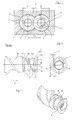
- the screw elements 1 on a frontal profile 2 which is composed of three circular arcs AB, EF and AE.
- the circular arc AB has a diameter corresponding to the outer diameter of the screw D, the circular arc EF a diameter corresponding to the screw core diameter d and the circular arc AE a diameter whose radius corresponds to the axial distance Ax of the two screw elements 1 (see. EP-B-0002131 ).
- the intermeshing screw elements 1 of the twin-screw extruder are mounted against rotation on two parallel, in the same direction rotating shafts 3, which are guided to the screw shafts 3 parallel circular segments 4 of the extruder housing 6, so that two gussets 5 are formed.
- FIGS. 2a to 2c has the two-start screw element 1 three concentric to the shaft axis 7 and arranged at a distance ring section 8.
- the ring sections 8 are provided here, relative to the conveying direction represented by the arrow 9, on the side of the screw element 1 facing the outlet of the extruder, ie, a long screw section 11a is provided in the conveying direction 9, against which the first two ring sections follow 8 two shorter screw sections 11b and 11c and after the third ring section 8 an even shorter screw section 11d connect.
- the distance of the ring sections 8 from one another corresponds to about one third of the screw diameter and the distance of the end face of the screw segment 11 d from the adjacent ring section 8 only about 1/6 D.
- the ring sections 8 are obtained by grooves 12 in the screw element 1.
- the angle ⁇ of the flanks 13 of the recesses 12 to the shaft axis 10 is about 60 degrees.
- the height of the annular gaps 14 between the ring sections 8 and the extruder housing 6 is after Figure 2c about half of the channel depth t, ie half the difference between the core diameter d and the outer diameter of the screw D ( FIG. 1 ).
- the diameter dr of the ring sections 8 thus corresponds approximately to the center distance Ax of the shafts 3 from each other.
- FIGS. 3a to 3c The screw element 1 after FIGS. 3a to 3c is different from that FIGS. 2a to 2c essentially in that, instead of the screw section 11a, a conveying-neutral section 15 is provided, which is formed by a corresponding material removal of the screw block of the screw element 1.
- the screw element 1 after FIGS. 3a to 3c is particularly suitable for an extruder having three or more screw elements arranged in a cavity of an extruder housing along a circle or circular arc with the same central angular distance, which divide the cavity into an inner and outer space.
- material balancing between the inner and the outer frame must take place in such ring extruders.
- the ring sections 8 and the short screw sections 11b, c and d of the screw element after FIGS. 3a to 3c inhibit the flow of product is allowed by the passage 15 a passage from one to the other process space.
- the screw element after FIG. 4 is different from that FIGS. 3a to 3c essentially in that only two ring sections 8 are provided, wherein the one ring section 8 is arranged between the one end face of the screw element 1 and the conveying neutral section 15, and two screw sections 11e and f separated by the second ring section 8 and a further screw section 11g between the end face of the screw element 1 and the ring portion 8 are provided on the portion 15.
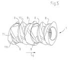
- FIG. 2 a is how in FIG. 2 a through the dashed Line 16 indicated, formed a continuous screw, which is interrupted only by the grooves 12 with the ring sections 8.
- the worm sections 11 h, i, j... between the ring sections 8 are arranged angularly offset with respect to one another in the same direction of rotation.
Landscapes
- Engineering & Computer Science (AREA)
- Mechanical Engineering (AREA)
- Physics & Mathematics (AREA)
- Algebra (AREA)
- General Physics & Mathematics (AREA)
- Mathematical Analysis (AREA)
- Mathematical Optimization (AREA)
- Mathematical Physics (AREA)
- Pure & Applied Mathematics (AREA)
- Extrusion Moulding Of Plastics Or The Like (AREA)
- Processing And Handling Of Plastics And Other Materials For Molding In General (AREA)
Claims (9)
- Extrudeuse permettant un travail et/ou un traitement continu(s) de substances coulantes, comportant au moins deux arbres (3) parallèles tournant dans le même sens qui sont pourvus d'éléments de vis sans fin qui s'engrènent les uns dans les autres, dont la face frontale est limitée par des arcs de cercle (A-B, E-F, A-E) qui correspondent au diamètre extérieur (D) de la vis sans fin, au diamètre central (d) de la vis sans fin et au maximum à l'écart axial (Ax) des éléments de vis sans fin et qui sont guidés sur des segments de cercle du boîtier (6) de l'extrudeuse, qui sont parallèles aux arbres, caractérisée en ce qu'au moins un élément de vis sans fin (1) présente plusieurs tronçons annulaires (8) concentriques agencés avec écart, avec des tronçons de vis sans fin (11 b, 11 c, 11i, i, 11j...) entre les tronçons annulaires (8), les tronçons annulaires (8) étant formes par des gorges (12) tournées dans la masse de la vis sans fin (1).
- Extrudeuse selon la revendication 1, caractérisée en ce que l'écart axial des tronçons annulaires (8) de l'élément de vis sans fin (1) n'est pas supérieur au diamètre extérieur (D) de la vis sans fin.
- Extrudeuse selon la revendication 1 ou 2, caractérisée en ce que l'écart axial des tronçons annulaires (8) de l'élément de vis sans fin (1) est d'au moins 1/10 du diamètre (D) de la vis sans fin.
- Extrudeuse selon l'une des revendications précédentes, caractérisée en ce que la hauteur (h) de la fente annulaire (14) entre les tronçons annulaires (8) et les segments de cercle (4) du boîtier (6) de l'extrudeuse correspond à un quart jusqu'à trois quarts de la profondeur (t) du pas de vis.
- Extrudeuse selon l'une des revendications précédentes, caractérisée en ce que le diamètre (d) des tronçons annulaires (8) correspond approximativement à l'écart axial (Ax) des arbres (3).
- Extrudeuse selon l'une des revendications précédentes, caractérisée en ce que les flancs (13) des tronçons annulaires (8) s'étendent en oblique par rapport à l'axe d'arbre (7).
- Extrudeuse selon l'une des revendications précédentes, caractérisée en ce que les tronçons de vis sans fin (11h, i, j ...) entre les tronçons annulaires (8) sont agencés avec le même sens de rotation en étant déplacés angulairement les uns par rapport aux autres de manière progressive.
- Extrudeuse selon l'une des revendications 1 à 6, caractérisée en ce que les tronçons de vis sans fin (11 a, b, c ...) de l'élément de vis sans fin (1) forment un pas de vis (16) continu, à l'exception de l'interruption dans la zone des tronçons annulaires (8).
- Dispositif selon l'une des revendications précédentes, caractérisé en ce que l'élément de vis sans fin (1) présente additionnellement au moins un tronçon neutre du point de vue transport (15).
Applications Claiming Priority (3)
| Application Number | Priority Date | Filing Date | Title |
|---|---|---|---|
| DE10233213A DE10233213B4 (de) | 2002-07-22 | 2002-07-22 | Extruder |
| DE10233213 | 2002-07-22 | ||
| PCT/EP2003/005074 WO2004009326A1 (fr) | 2002-07-22 | 2003-05-14 | Extrudeuse |
Publications (2)
| Publication Number | Publication Date |
|---|---|
| EP1523403A1 EP1523403A1 (fr) | 2005-04-20 |
| EP1523403B1 true EP1523403B1 (fr) | 2014-09-24 |
Family
ID=30469027
Family Applications (1)
| Application Number | Title | Priority Date | Filing Date |
|---|---|---|---|
| EP03730036.5A Expired - Lifetime EP1523403B1 (fr) | 2002-07-22 | 2003-05-14 | Extrudeuse |
Country Status (6)
| Country | Link |
|---|---|
| US (1) | US7270471B2 (fr) |
| EP (1) | EP1523403B1 (fr) |
| JP (1) | JP4369366B2 (fr) |
| DE (1) | DE10233213B4 (fr) |
| ES (1) | ES2523296T3 (fr) |
| WO (1) | WO2004009326A1 (fr) |
Families Citing this family (22)
| Publication number | Priority date | Publication date | Assignee | Title |
|---|---|---|---|---|
| DE10233213B4 (de) * | 2002-07-22 | 2004-09-09 | 3+Extruder Gmbh | Extruder |
| DE10233214B4 (de) * | 2002-07-22 | 2005-01-27 | 3+Extruder Gmbh | Extruder zum kontinuierlichen Bearbeiten und/oder Verarbeiten von fließfähigen Materialien |
| DE102004052055B4 (de) * | 2004-10-26 | 2014-11-20 | Blach Verwaltung Gmbh & Co.Kg | Extruder |
| DE102005053907B4 (de) * | 2005-11-11 | 2009-05-20 | Blach Verwaltung Gmbh & Co.Kg | Mehrwellenextruder |
| EP1832281A1 (fr) | 2006-03-10 | 2007-09-12 | Abbott GmbH & Co. KG | Procédé pour la production d'une dispersion solide d'un ingredient actif |
| DE102006014692B3 (de) * | 2006-03-28 | 2007-08-02 | Berstorff Gmbh | Schneckenelement |
| DE102007016346A1 (de) * | 2007-04-03 | 2008-10-09 | Blach Verwaltungs Gmbh & Co. Kg | Mehrwellenextrudervorrichtung und Verfahren zum Betreiben derselben |
| JP4746014B2 (ja) * | 2007-07-09 | 2011-08-10 | 株式会社日本製鋼所 | 溶融混練脱揮押出機 |
| WO2009021334A1 (fr) * | 2007-08-15 | 2009-02-19 | Ivan Askgaard | Système et procédé de propulsion pour traversier à câbles |
| DE102008016862C5 (de) * | 2008-04-02 | 2019-12-19 | Blach Verwaltungs Gmbh & Co. Kg | Extruder |
| DE102008029304A1 (de) * | 2008-06-20 | 2009-12-24 | Bayer Technology Services Gmbh | Verfahren zur Erzeugung von Schneckenelementen |
| US20100052206A1 (en) * | 2008-08-29 | 2010-03-04 | Christopher Lane Kerr | Extrusion Mixing Screw And Method Of Use |
| ES2584514T3 (es) * | 2009-07-16 | 2016-09-28 | Blach Verwaltungs Gmbh & Co. Kg | Extrusora |
| DE102009057139A1 (de) * | 2009-12-08 | 2011-06-09 | Bayer Technology Services Gmbh | Verfahren zur Konstruktion gleichsinnig rotierender, sich berührender Körper |
| AT509710B1 (de) | 2010-03-24 | 2011-11-15 | Josef Ing Blach | Extruder |
| JP4829372B1 (ja) * | 2010-08-12 | 2011-12-07 | ファナック株式会社 | 射出成形機の材料供給装置のスクリュ |
| US9180511B2 (en) | 2012-04-12 | 2015-11-10 | Rel, Inc. | Thermal isolation for casting articles |
| FR3007685B1 (fr) * | 2013-06-27 | 2016-02-05 | Clextral | Element de vis pour une extrudeuse bivis corotative, ainsi qu'extrudeuse bivis corotative correspondante |
| JP7180244B2 (ja) * | 2018-09-27 | 2022-11-30 | セイコーエプソン株式会社 | 可塑化装置 |
| CN110901016B (zh) * | 2019-11-04 | 2021-09-03 | 大维塑料技术(南京)有限公司 | 一种挤塑机的螺杆 |
| CN118829534A (zh) | 2022-03-11 | 2024-10-22 | 科思创德国股份有限公司 | 具有改进的混合效果和压力建立的螺杆元件 |
| EP4458548A1 (fr) | 2023-05-04 | 2024-11-06 | Covestro Deutschland AG | Éléments de vis à effet de mélange amélioré et à transfert de chaleur amélioré et utilisation de ceux-ci |
Family Cites Families (25)
| Publication number | Priority date | Publication date | Assignee | Title |
|---|---|---|---|---|
| DE813154C (de) * | 1949-09-29 | 1951-09-06 | Bayer Ag | Misch- und Knetvorrichtung |
| DE974124C (de) * | 1950-03-08 | 1960-09-22 | Carlo Pasquetti | Schraubenpresse fuer die Verarbeitung thermoplastischer Werkstoffe |
| CA925670A (en) * | 1970-01-28 | 1973-05-08 | P. Fritsch Rudolf | Apparatus for plastifying of particulate synthetic plastics |
| JPS5829733B2 (ja) * | 1977-11-19 | 1983-06-24 | 積水化学工業株式会社 | 押出機 |
| DE2854207C3 (de) | 1978-12-15 | 1984-06-20 | Basf Ag, 6700 Ludwigshafen | Schneckenextruder zum kontinuierlichen Aufbereiten plastifizierbarer Massen |
| DE2934297A1 (de) * | 1979-08-24 | 1981-03-26 | Eberhard Dipl.-Ing. 7000 Stuttgart Grünschloß | Mehrgaengige extruderschnecke |
| DD159836A3 (de) * | 1981-05-06 | 1983-04-13 | Dieter Andersch | Stau-und mischelement fuer doppelschneckenextruder |
| GB8712545D0 (en) * | 1987-05-28 | 1987-07-01 | Unilever Plc | High shear mixing |
| JPH0262222A (ja) * | 1988-08-30 | 1990-03-02 | Mitsubishi Heavy Ind Ltd | 押出機の圧力調整装置 |
| DE3841728C1 (de) * | 1988-12-10 | 1990-03-01 | Hermann Berstorff Maschinenbau Gmbh, 30627 Hannover | Ein- oder Doppelschneckenextruder zum Einarbeiten von pulverförmigen oder faserförmigen Additiven in eine thermoplastische Kunststoffschmelze |
| DE3841729C1 (de) * | 1988-12-10 | 1990-03-01 | Hermann Berstorff Maschinenbau Gmbh, 30627 Hannover | Ein- oder Doppelschneckenextruder zum Entgasen von thermoplastischen Kunststoffschmelzen |
| DE3843576A1 (de) * | 1988-12-23 | 1990-07-12 | Jv Kunststoffwerk | Verfahren und vorrichtung zur herstellung von kunststoffformteilen |
| DE58907012D1 (de) | 1989-10-12 | 1994-03-24 | Josef A Blach | Misch- und Knetvorrichtung. |
| JPH0677679B2 (ja) * | 1991-07-29 | 1994-10-05 | ビーエイチ工業有限会社 | 連続捏和機 |
| JPH0677680B2 (ja) * | 1991-08-16 | 1994-10-05 | ビーエイチ工業有限会社 | 連続捏和機 |
| JP2986702B2 (ja) * | 1995-01-31 | 1999-12-06 | 株式会社日本製鋼所 | 可塑化装置のスクリュー及び可塑化方法 |
| US5630968A (en) * | 1995-06-07 | 1997-05-20 | The Japan Steel Works, Ltd. | Water-injection foaming devolatilizing method |
| ATE181867T1 (de) * | 1996-02-06 | 1999-07-15 | Josef A Blach | Vorrichtung zum kontinuierlichen bearbeiten von fliessfähigen materialien |
| DE19847102C1 (de) * | 1998-10-13 | 2000-01-05 | 3 & Extruder Gmbh | Maschine zum kontinuierlichen Bearbeiten von fließfähigen Materialien |
| JP4377978B2 (ja) * | 1998-11-17 | 2009-12-02 | 住友化学株式会社 | 組成物の製造方法 |
| JP4670173B2 (ja) * | 2000-05-12 | 2011-04-13 | 株式会社デンソー | 押出成形装置 |
| DE10122462C1 (de) * | 2001-05-09 | 2002-10-10 | 3 & Extruder Gmbh | Vorrichtung mit Schnecken zum Homogenisieren und/oder Dispergieren eines viskosen Stoffes und eines Feststoffes und/oder eines anderen Stoffes unterschiedlicher Viskosität |
| DE10207145B4 (de) * | 2002-02-20 | 2004-07-15 | Blach, Josef A. | Vorrichtung zum Dispergieren und Aufschmelzen fließfähiger Stoffe |
| DE10233214B4 (de) * | 2002-07-22 | 2005-01-27 | 3+Extruder Gmbh | Extruder zum kontinuierlichen Bearbeiten und/oder Verarbeiten von fließfähigen Materialien |
| DE10233213B4 (de) * | 2002-07-22 | 2004-09-09 | 3+Extruder Gmbh | Extruder |
-
2002
- 2002-07-22 DE DE10233213A patent/DE10233213B4/de not_active Expired - Lifetime
-
2003
- 2003-05-14 US US10/503,143 patent/US7270471B2/en not_active Expired - Lifetime
- 2003-05-14 WO PCT/EP2003/005074 patent/WO2004009326A1/fr not_active Ceased
- 2003-05-14 JP JP2004522162A patent/JP4369366B2/ja not_active Expired - Lifetime
- 2003-05-14 EP EP03730036.5A patent/EP1523403B1/fr not_active Expired - Lifetime
- 2003-05-14 ES ES03730036.5T patent/ES2523296T3/es not_active Expired - Lifetime
Also Published As
| Publication number | Publication date |
|---|---|
| ES2523296T3 (es) | 2014-11-24 |
| EP1523403A1 (fr) | 2005-04-20 |
| US20050084559A1 (en) | 2005-04-21 |
| DE10233213B4 (de) | 2004-09-09 |
| WO2004009326A1 (fr) | 2004-01-29 |
| JP2005533681A (ja) | 2005-11-10 |
| US7270471B2 (en) | 2007-09-18 |
| JP4369366B2 (ja) | 2009-11-18 |
| DE10233213A1 (de) | 2004-02-19 |
Similar Documents
| Publication | Publication Date | Title |
|---|---|---|
| EP1523403B1 (fr) | Extrudeuse | |
| DE4134026C2 (de) | Gleichdrallschneckenkneter | |
| EP1526959B1 (fr) | Extrudeuse destinee au traitement continu de materiaux coulants | |
| DE69519431T2 (de) | Mehrschneckenextruder mit modularen mischelementen | |
| AT509710B1 (de) | Extruder | |
| DE102008016862B4 (de) | Extruder | |
| CH630285A5 (de) | Vorrichtung zum kontinuierlichen mischen fliessfaehiger materialien. | |
| EP0346757A2 (fr) | Extrudeuse à deux vis | |
| DE1502335B2 (de) | Schneckenstrangprese fuer die verarbeitung von kunststoff | |
| DE2550969A1 (de) | Schneckenmaschine zum homogenisieren von festen, fluessigen und zaehviskosen materialien | |
| EP1829660A2 (fr) | Machine de mélange et de malaxage pour masses en plastiques | |
| EP3473396A1 (fr) | Arbre de vis sans fin à deux ailettes pour machine de mélange et de pétrissage | |
| EP2272651B1 (fr) | Machine à vis sans fin avec élément de malaxage dispersif | |
| DE10114727B4 (de) | Schneckenelement für gleichsinnig drehende Mehrschneckenextruder | |
| DE2019522C3 (de) | Schneckenpresse für thermoplastische Kunststoffe und unvernetzte Elastomere | |
| EP1434679B2 (fr) | Extrudeuse annulaire a elements de refoulement a contreforts partiels dans la zone d'alimentation | |
| DE2702390A1 (de) | Vorrichtung zum aufbereiten und strangpressen von thermoplastischen kunststoffen | |
| DE102012008169A1 (de) | Extruder mit Materialeintrag durch Gehäuse | |
| EP3093119A1 (fr) | Vis d'extrudeuse et procede de sa reequipement | |
| EP0490362B1 (fr) | Extrudeuse à haut rendement à nombre de filets constant dans la zone d'entrée et dans la zone de sortie d'un élément de cisaillement par transfert | |
| EP0012795B1 (fr) | Boudineuse à vis pour le travail de matières plastiques, de caoutchouc ou analogues | |
| DE2357945C3 (de) | Schneckenextruder zur kontinuierlichen Verarbeitung von plastischen Massen | |
| EP3253554B1 (fr) | Vis de gavage | |
| DE2802125A1 (de) | Schneckenmaschine zum bearbeiten von festen, fluessigen und zaehviskosen materialien | |
| DE102004050810A1 (de) | Einwellige, kontinuierlich arbeitende Misch- und Knetmaschine |
Legal Events
| Date | Code | Title | Description |
|---|---|---|---|
| PUAI | Public reference made under article 153(3) epc to a published international application that has entered the european phase |
Free format text: ORIGINAL CODE: 0009012 |
|
| 17P | Request for examination filed |
Effective date: 20040207 |
|
| AK | Designated contracting states |
Kind code of ref document: A1 Designated state(s): AT BE BG CH CY CZ DE DK EE ES FI FR GB GR HU IE IT LI LU MC NL PT RO SE SI SK TR |
|
| RAP1 | Party data changed (applicant data changed or rights of an application transferred) |
Owner name: BLACH VERWALTUNGS GMBH & CO. KG |
|
| 17Q | First examination report despatched |
Effective date: 20101228 |
|
| GRAP | Despatch of communication of intention to grant a patent |
Free format text: ORIGINAL CODE: EPIDOSNIGR1 |
|
| INTG | Intention to grant announced |
Effective date: 20140630 |
|
| GRAS | Grant fee paid |
Free format text: ORIGINAL CODE: EPIDOSNIGR3 |
|
| GRAA | (expected) grant |
Free format text: ORIGINAL CODE: 0009210 |
|
| AK | Designated contracting states |
Kind code of ref document: B1 Designated state(s): AT BE BG CH CY CZ DE DK EE ES FI FR GB GR HU IE IT LI LU MC NL PT RO SE SI SK TR |
|
| REG | Reference to a national code |
Ref country code: GB Ref legal event code: FG4D Free format text: NOT ENGLISH |
|
| REG | Reference to a national code |
Ref country code: CH Ref legal event code: EP |
|
| REG | Reference to a national code |
Ref country code: AT Ref legal event code: REF Ref document number: 688404 Country of ref document: AT Kind code of ref document: T Effective date: 20141015 |
|
| REG | Reference to a national code |
Ref country code: IE Ref legal event code: FG4D Free format text: LANGUAGE OF EP DOCUMENT: GERMAN |
|
| REG | Reference to a national code |
Ref country code: DE Ref legal event code: R096 Ref document number: 50315137 Country of ref document: DE Effective date: 20141106 |
|
| REG | Reference to a national code |
Ref country code: ES Ref legal event code: FG2A Ref document number: 2523296 Country of ref document: ES Kind code of ref document: T3 Effective date: 20141124 |
|
| PG25 | Lapsed in a contracting state [announced via postgrant information from national office to epo] |
Ref country code: SE Free format text: LAPSE BECAUSE OF FAILURE TO SUBMIT A TRANSLATION OF THE DESCRIPTION OR TO PAY THE FEE WITHIN THE PRESCRIBED TIME-LIMIT Effective date: 20140924 Ref country code: FI Free format text: LAPSE BECAUSE OF FAILURE TO SUBMIT A TRANSLATION OF THE DESCRIPTION OR TO PAY THE FEE WITHIN THE PRESCRIBED TIME-LIMIT Effective date: 20140924 Ref country code: GR Free format text: LAPSE BECAUSE OF FAILURE TO SUBMIT A TRANSLATION OF THE DESCRIPTION OR TO PAY THE FEE WITHIN THE PRESCRIBED TIME-LIMIT Effective date: 20141225 |
|
| REG | Reference to a national code |
Ref country code: CH Ref legal event code: NV Representative=s name: KLOTER AND KOHLI RECHTSANWAELTE, CH |
|
| REG | Reference to a national code |
Ref country code: NL Ref legal event code: VDEP Effective date: 20140924 |
|
| PG25 | Lapsed in a contracting state [announced via postgrant information from national office to epo] |
Ref country code: CY Free format text: LAPSE BECAUSE OF FAILURE TO SUBMIT A TRANSLATION OF THE DESCRIPTION OR TO PAY THE FEE WITHIN THE PRESCRIBED TIME-LIMIT Effective date: 20140924 |
|
| PG25 | Lapsed in a contracting state [announced via postgrant information from national office to epo] |
Ref country code: NL Free format text: LAPSE BECAUSE OF FAILURE TO SUBMIT A TRANSLATION OF THE DESCRIPTION OR TO PAY THE FEE WITHIN THE PRESCRIBED TIME-LIMIT Effective date: 20140924 |
|
| PG25 | Lapsed in a contracting state [announced via postgrant information from national office to epo] |
Ref country code: EE Free format text: LAPSE BECAUSE OF FAILURE TO SUBMIT A TRANSLATION OF THE DESCRIPTION OR TO PAY THE FEE WITHIN THE PRESCRIBED TIME-LIMIT Effective date: 20140924 Ref country code: CZ Free format text: LAPSE BECAUSE OF FAILURE TO SUBMIT A TRANSLATION OF THE DESCRIPTION OR TO PAY THE FEE WITHIN THE PRESCRIBED TIME-LIMIT Effective date: 20140924 Ref country code: SK Free format text: LAPSE BECAUSE OF FAILURE TO SUBMIT A TRANSLATION OF THE DESCRIPTION OR TO PAY THE FEE WITHIN THE PRESCRIBED TIME-LIMIT Effective date: 20140924 Ref country code: PT Free format text: LAPSE BECAUSE OF FAILURE TO SUBMIT A TRANSLATION OF THE DESCRIPTION OR TO PAY THE FEE WITHIN THE PRESCRIBED TIME-LIMIT Effective date: 20150126 Ref country code: RO Free format text: LAPSE BECAUSE OF FAILURE TO SUBMIT A TRANSLATION OF THE DESCRIPTION OR TO PAY THE FEE WITHIN THE PRESCRIBED TIME-LIMIT Effective date: 20140924 |
|
| REG | Reference to a national code |
Ref country code: DE Ref legal event code: R097 Ref document number: 50315137 Country of ref document: DE |
|
| PG25 | Lapsed in a contracting state [announced via postgrant information from national office to epo] |
Ref country code: DK Free format text: LAPSE BECAUSE OF FAILURE TO SUBMIT A TRANSLATION OF THE DESCRIPTION OR TO PAY THE FEE WITHIN THE PRESCRIBED TIME-LIMIT Effective date: 20140924 |
|
| PLBE | No opposition filed within time limit |
Free format text: ORIGINAL CODE: 0009261 |
|
| STAA | Information on the status of an ep patent application or granted ep patent |
Free format text: STATUS: NO OPPOSITION FILED WITHIN TIME LIMIT |
|
| 26N | No opposition filed |
Effective date: 20150625 |
|
| REG | Reference to a national code |
Ref country code: CH Ref legal event code: PCAR Free format text: NEW ADDRESS: FORCHSTRASSE 30 POSTFACH, 8032 ZUERICH (CH) |
|
| GBPC | Gb: european patent ceased through non-payment of renewal fee |
Effective date: 20150514 |
|
| PG25 | Lapsed in a contracting state [announced via postgrant information from national office to epo] |
Ref country code: MC Free format text: LAPSE BECAUSE OF FAILURE TO SUBMIT A TRANSLATION OF THE DESCRIPTION OR TO PAY THE FEE WITHIN THE PRESCRIBED TIME-LIMIT Effective date: 20140924 Ref country code: LU Free format text: LAPSE BECAUSE OF FAILURE TO SUBMIT A TRANSLATION OF THE DESCRIPTION OR TO PAY THE FEE WITHIN THE PRESCRIBED TIME-LIMIT Effective date: 20150514 |
|
| REG | Reference to a national code |
Ref country code: IE Ref legal event code: MM4A |
|
| PG25 | Lapsed in a contracting state [announced via postgrant information from national office to epo] |
Ref country code: SI Free format text: LAPSE BECAUSE OF FAILURE TO SUBMIT A TRANSLATION OF THE DESCRIPTION OR TO PAY THE FEE WITHIN THE PRESCRIBED TIME-LIMIT Effective date: 20140924 |
|
| REG | Reference to a national code |
Ref country code: FR Ref legal event code: PLFP Year of fee payment: 14 |
|
| PG25 | Lapsed in a contracting state [announced via postgrant information from national office to epo] |
Ref country code: GB Free format text: LAPSE BECAUSE OF NON-PAYMENT OF DUE FEES Effective date: 20150514 Ref country code: IE Free format text: LAPSE BECAUSE OF NON-PAYMENT OF DUE FEES Effective date: 20150514 |
|
| PG25 | Lapsed in a contracting state [announced via postgrant information from national office to epo] |
Ref country code: HU Free format text: LAPSE BECAUSE OF FAILURE TO SUBMIT A TRANSLATION OF THE DESCRIPTION OR TO PAY THE FEE WITHIN THE PRESCRIBED TIME-LIMIT; INVALID AB INITIO Effective date: 20030514 Ref country code: BG Free format text: LAPSE BECAUSE OF FAILURE TO SUBMIT A TRANSLATION OF THE DESCRIPTION OR TO PAY THE FEE WITHIN THE PRESCRIBED TIME-LIMIT Effective date: 20140924 |
|
| REG | Reference to a national code |
Ref country code: FR Ref legal event code: PLFP Year of fee payment: 15 |
|
| PG25 | Lapsed in a contracting state [announced via postgrant information from national office to epo] |
Ref country code: BE Free format text: LAPSE BECAUSE OF NON-PAYMENT OF DUE FEES Effective date: 20150531 |
|
| PG25 | Lapsed in a contracting state [announced via postgrant information from national office to epo] |
Ref country code: TR Free format text: LAPSE BECAUSE OF FAILURE TO SUBMIT A TRANSLATION OF THE DESCRIPTION OR TO PAY THE FEE WITHIN THE PRESCRIBED TIME-LIMIT Effective date: 20140924 |
|
| REG | Reference to a national code |
Ref country code: CH Ref legal event code: PFA Owner name: BLACH VERWALTUNGS GMBH AND CO. KG, DE Free format text: FORMER OWNER: BLACH VERWALTUNGS GMBH AND CO. KG, DE |
|
| REG | Reference to a national code |
Ref country code: FR Ref legal event code: PLFP Year of fee payment: 16 |
|
| REG | Reference to a national code |
Ref country code: DE Ref legal event code: R079 Ref document number: 50315137 Country of ref document: DE Free format text: PREVIOUS MAIN CLASS: B29C0047400000 Ipc: B29C0048400000 |
|
| PGFP | Annual fee paid to national office [announced via postgrant information from national office to epo] |
Ref country code: FR Payment date: 20220331 Year of fee payment: 20 |
|
| PGFP | Annual fee paid to national office [announced via postgrant information from national office to epo] |
Ref country code: IT Payment date: 20220524 Year of fee payment: 20 Ref country code: ES Payment date: 20220601 Year of fee payment: 20 Ref country code: DE Payment date: 20220524 Year of fee payment: 20 |
|
| PGFP | Annual fee paid to national office [announced via postgrant information from national office to epo] |
Ref country code: CH Payment date: 20220524 Year of fee payment: 20 Ref country code: AT Payment date: 20220524 Year of fee payment: 20 |
|
| REG | Reference to a national code |
Ref country code: DE Ref legal event code: R071 Ref document number: 50315137 Country of ref document: DE |
|
| REG | Reference to a national code |
Ref country code: CH Ref legal event code: PL |
|
| REG | Reference to a national code |
Ref country code: ES Ref legal event code: FD2A Effective date: 20230526 |
|
| REG | Reference to a national code |
Ref country code: AT Ref legal event code: MK07 Ref document number: 688404 Country of ref document: AT Kind code of ref document: T Effective date: 20230514 |
|
| PG25 | Lapsed in a contracting state [announced via postgrant information from national office to epo] |
Ref country code: ES Free format text: LAPSE BECAUSE OF EXPIRATION OF PROTECTION Effective date: 20230515 |