EP1523403B1 - Extruder - Google Patents
Extruder Download PDFInfo
- Publication number
- EP1523403B1 EP1523403B1 EP03730036.5A EP03730036A EP1523403B1 EP 1523403 B1 EP1523403 B1 EP 1523403B1 EP 03730036 A EP03730036 A EP 03730036A EP 1523403 B1 EP1523403 B1 EP 1523403B1
- Authority
- EP
- European Patent Office
- Prior art keywords
- screw
- sections
- extruder
- annular sections
- screw element
- Prior art date
- Legal status (The legal status is an assumption and is not a legal conclusion. Google has not performed a legal analysis and makes no representation as to the accuracy of the status listed.)
- Expired - Lifetime
Links
- 239000000126 substance Substances 0.000 claims description 8
- 239000000463 material Substances 0.000 description 9
- 238000004898 kneading Methods 0.000 description 3
- 238000007789 sealing Methods 0.000 description 3
- 238000000034 method Methods 0.000 description 2
- 230000007935 neutral effect Effects 0.000 description 2
- 238000010008 shearing Methods 0.000 description 2
- 230000000694 effects Effects 0.000 description 1
- 238000005516 engineering process Methods 0.000 description 1
- 239000004744 fabric Substances 0.000 description 1
- 230000009969 flowable effect Effects 0.000 description 1
- 238000010438 heat treatment Methods 0.000 description 1
- 230000002045 lasting effect Effects 0.000 description 1
- 239000007788 liquid Substances 0.000 description 1
- 230000001737 promoting effect Effects 0.000 description 1
- 230000007704 transition Effects 0.000 description 1
- -1 viscous Substances 0.000 description 1
Images


Classifications
-
- B—PERFORMING OPERATIONS; TRANSPORTING
- B29—WORKING OF PLASTICS; WORKING OF SUBSTANCES IN A PLASTIC STATE IN GENERAL
- B29B—PREPARATION OR PRETREATMENT OF THE MATERIAL TO BE SHAPED; MAKING GRANULES OR PREFORMS; RECOVERY OF PLASTICS OR OTHER CONSTITUENTS OF WASTE MATERIAL CONTAINING PLASTICS
- B29B7/00—Mixing; Kneading
- B29B7/30—Mixing; Kneading continuous, with mechanical mixing or kneading devices
- B29B7/34—Mixing; Kneading continuous, with mechanical mixing or kneading devices with movable mixing or kneading devices
- B29B7/38—Mixing; Kneading continuous, with mechanical mixing or kneading devices with movable mixing or kneading devices rotary
- B29B7/46—Mixing; Kneading continuous, with mechanical mixing or kneading devices with movable mixing or kneading devices rotary with more than one shaft
- B29B7/48—Mixing; Kneading continuous, with mechanical mixing or kneading devices with movable mixing or kneading devices rotary with more than one shaft with intermeshing devices, e.g. screws
- B29B7/481—Mixing; Kneading continuous, with mechanical mixing or kneading devices with movable mixing or kneading devices rotary with more than one shaft with intermeshing devices, e.g. screws provided with paddles, gears or discs
-
- B—PERFORMING OPERATIONS; TRANSPORTING
- B29—WORKING OF PLASTICS; WORKING OF SUBSTANCES IN A PLASTIC STATE IN GENERAL
- B29B—PREPARATION OR PRETREATMENT OF THE MATERIAL TO BE SHAPED; MAKING GRANULES OR PREFORMS; RECOVERY OF PLASTICS OR OTHER CONSTITUENTS OF WASTE MATERIAL CONTAINING PLASTICS
- B29B7/00—Mixing; Kneading
- B29B7/30—Mixing; Kneading continuous, with mechanical mixing or kneading devices
- B29B7/34—Mixing; Kneading continuous, with mechanical mixing or kneading devices with movable mixing or kneading devices
- B29B7/38—Mixing; Kneading continuous, with mechanical mixing or kneading devices with movable mixing or kneading devices rotary
- B29B7/46—Mixing; Kneading continuous, with mechanical mixing or kneading devices with movable mixing or kneading devices rotary with more than one shaft
- B29B7/48—Mixing; Kneading continuous, with mechanical mixing or kneading devices with movable mixing or kneading devices rotary with more than one shaft with intermeshing devices, e.g. screws
- B29B7/482—Mixing; Kneading continuous, with mechanical mixing or kneading devices with movable mixing or kneading devices rotary with more than one shaft with intermeshing devices, e.g. screws provided with screw parts in addition to other mixing parts, e.g. paddles, gears, discs
- B29B7/483—Mixing; Kneading continuous, with mechanical mixing or kneading devices with movable mixing or kneading devices rotary with more than one shaft with intermeshing devices, e.g. screws provided with screw parts in addition to other mixing parts, e.g. paddles, gears, discs the other mixing parts being discs perpendicular to the screw axis
-
- B—PERFORMING OPERATIONS; TRANSPORTING
- B29—WORKING OF PLASTICS; WORKING OF SUBSTANCES IN A PLASTIC STATE IN GENERAL
- B29B—PREPARATION OR PRETREATMENT OF THE MATERIAL TO BE SHAPED; MAKING GRANULES OR PREFORMS; RECOVERY OF PLASTICS OR OTHER CONSTITUENTS OF WASTE MATERIAL CONTAINING PLASTICS
- B29B7/00—Mixing; Kneading
- B29B7/30—Mixing; Kneading continuous, with mechanical mixing or kneading devices
- B29B7/34—Mixing; Kneading continuous, with mechanical mixing or kneading devices with movable mixing or kneading devices
- B29B7/38—Mixing; Kneading continuous, with mechanical mixing or kneading devices with movable mixing or kneading devices rotary
- B29B7/46—Mixing; Kneading continuous, with mechanical mixing or kneading devices with movable mixing or kneading devices rotary with more than one shaft
- B29B7/48—Mixing; Kneading continuous, with mechanical mixing or kneading devices with movable mixing or kneading devices rotary with more than one shaft with intermeshing devices, e.g. screws
- B29B7/488—Parts, e.g. casings, sealings; Accessories, e.g. flow controlling or throttling devices
- B29B7/489—Screws
-
- B—PERFORMING OPERATIONS; TRANSPORTING
- B29—WORKING OF PLASTICS; WORKING OF SUBSTANCES IN A PLASTIC STATE IN GENERAL
- B29C—SHAPING OR JOINING OF PLASTICS; SHAPING OF MATERIAL IN A PLASTIC STATE, NOT OTHERWISE PROVIDED FOR; AFTER-TREATMENT OF THE SHAPED PRODUCTS, e.g. REPAIRING
- B29C48/00—Extrusion moulding, i.e. expressing the moulding material through a die or nozzle which imparts the desired form; Apparatus therefor
- B29C48/25—Component parts, details or accessories; Auxiliary operations
- B29C48/251—Design of extruder parts, e.g. by modelling based on mathematical theories or experiments
- B29C48/2517—Design of extruder parts, e.g. by modelling based on mathematical theories or experiments of intermeshing screws
-
- B—PERFORMING OPERATIONS; TRANSPORTING
- B29—WORKING OF PLASTICS; WORKING OF SUBSTANCES IN A PLASTIC STATE IN GENERAL
- B29C—SHAPING OR JOINING OF PLASTICS; SHAPING OF MATERIAL IN A PLASTIC STATE, NOT OTHERWISE PROVIDED FOR; AFTER-TREATMENT OF THE SHAPED PRODUCTS, e.g. REPAIRING
- B29C48/00—Extrusion moulding, i.e. expressing the moulding material through a die or nozzle which imparts the desired form; Apparatus therefor
- B29C48/25—Component parts, details or accessories; Auxiliary operations
- B29C48/256—Exchangeable extruder parts
- B29C48/2564—Screw parts
-
- B—PERFORMING OPERATIONS; TRANSPORTING
- B29—WORKING OF PLASTICS; WORKING OF SUBSTANCES IN A PLASTIC STATE IN GENERAL
- B29C—SHAPING OR JOINING OF PLASTICS; SHAPING OF MATERIAL IN A PLASTIC STATE, NOT OTHERWISE PROVIDED FOR; AFTER-TREATMENT OF THE SHAPED PRODUCTS, e.g. REPAIRING
- B29C48/00—Extrusion moulding, i.e. expressing the moulding material through a die or nozzle which imparts the desired form; Apparatus therefor
- B29C48/25—Component parts, details or accessories; Auxiliary operations
- B29C48/36—Means for plasticising or homogenising the moulding material or forcing it through the nozzle or die
- B29C48/395—Means for plasticising or homogenising the moulding material or forcing it through the nozzle or die using screws surrounded by a cooperating barrel, e.g. single screw extruders
- B29C48/40—Means for plasticising or homogenising the moulding material or forcing it through the nozzle or die using screws surrounded by a cooperating barrel, e.g. single screw extruders using two or more parallel screws or at least two parallel non-intermeshing screws, e.g. twin screw extruders
- B29C48/402—Means for plasticising or homogenising the moulding material or forcing it through the nozzle or die using screws surrounded by a cooperating barrel, e.g. single screw extruders using two or more parallel screws or at least two parallel non-intermeshing screws, e.g. twin screw extruders the screws having intermeshing parts
-
- B—PERFORMING OPERATIONS; TRANSPORTING
- B29—WORKING OF PLASTICS; WORKING OF SUBSTANCES IN A PLASTIC STATE IN GENERAL
- B29C—SHAPING OR JOINING OF PLASTICS; SHAPING OF MATERIAL IN A PLASTIC STATE, NOT OTHERWISE PROVIDED FOR; AFTER-TREATMENT OF THE SHAPED PRODUCTS, e.g. REPAIRING
- B29C48/00—Extrusion moulding, i.e. expressing the moulding material through a die or nozzle which imparts the desired form; Apparatus therefor
- B29C48/25—Component parts, details or accessories; Auxiliary operations
- B29C48/36—Means for plasticising or homogenising the moulding material or forcing it through the nozzle or die
- B29C48/395—Means for plasticising or homogenising the moulding material or forcing it through the nozzle or die using screws surrounded by a cooperating barrel, e.g. single screw extruders
- B29C48/40—Means for plasticising or homogenising the moulding material or forcing it through the nozzle or die using screws surrounded by a cooperating barrel, e.g. single screw extruders using two or more parallel screws or at least two parallel non-intermeshing screws, e.g. twin screw extruders
- B29C48/405—Intermeshing co-rotating screws
-
- B—PERFORMING OPERATIONS; TRANSPORTING
- B29—WORKING OF PLASTICS; WORKING OF SUBSTANCES IN A PLASTIC STATE IN GENERAL
- B29C—SHAPING OR JOINING OF PLASTICS; SHAPING OF MATERIAL IN A PLASTIC STATE, NOT OTHERWISE PROVIDED FOR; AFTER-TREATMENT OF THE SHAPED PRODUCTS, e.g. REPAIRING
- B29C48/00—Extrusion moulding, i.e. expressing the moulding material through a die or nozzle which imparts the desired form; Apparatus therefor
- B29C48/25—Component parts, details or accessories; Auxiliary operations
- B29C48/36—Means for plasticising or homogenising the moulding material or forcing it through the nozzle or die
- B29C48/50—Details of extruders
- B29C48/505—Screws
- B29C48/57—Screws provided with kneading disc-like elements, e.g. with oval-shaped elements
-
- B—PERFORMING OPERATIONS; TRANSPORTING
- B29—WORKING OF PLASTICS; WORKING OF SUBSTANCES IN A PLASTIC STATE IN GENERAL
- B29C—SHAPING OR JOINING OF PLASTICS; SHAPING OF MATERIAL IN A PLASTIC STATE, NOT OTHERWISE PROVIDED FOR; AFTER-TREATMENT OF THE SHAPED PRODUCTS, e.g. REPAIRING
- B29C48/00—Extrusion moulding, i.e. expressing the moulding material through a die or nozzle which imparts the desired form; Apparatus therefor
- B29C48/25—Component parts, details or accessories; Auxiliary operations
- B29C48/36—Means for plasticising or homogenising the moulding material or forcing it through the nozzle or die
- B29C48/50—Details of extruders
- B29C48/505—Screws
- B29C48/575—Screws provided with elements of a generally circular cross-section for shearing the melt, i.e. shear-ring elements
-
- B—PERFORMING OPERATIONS; TRANSPORTING
- B29—WORKING OF PLASTICS; WORKING OF SUBSTANCES IN A PLASTIC STATE IN GENERAL
- B29C—SHAPING OR JOINING OF PLASTICS; SHAPING OF MATERIAL IN A PLASTIC STATE, NOT OTHERWISE PROVIDED FOR; AFTER-TREATMENT OF THE SHAPED PRODUCTS, e.g. REPAIRING
- B29C48/00—Extrusion moulding, i.e. expressing the moulding material through a die or nozzle which imparts the desired form; Apparatus therefor
- B29C48/25—Component parts, details or accessories; Auxiliary operations
- B29C48/36—Means for plasticising or homogenising the moulding material or forcing it through the nozzle or die
- B29C48/50—Details of extruders
- B29C48/505—Screws
- B29C48/67—Screws having incorporated mixing devices not provided for in groups B29C48/52 - B29C48/66
Definitions
- the invention relates to an extruder for the continuous processing and / or processing of flowable substances according to the preamble of claim 1.
- kneading blocks are used in twin-screw extruders, which consist of spiral staircases arranged offset cams (see. DE-C-813154 ).
- the material is pressed through a narrow wedge gap between the cams and the extruder housing, which may result in a different heating and partial overstress due to shearing of the substance, also causes a locally above-average wear.
- JP 02 062222 discloses a twin-screw extruder with annular sections which are axially adjustable with respect to an enlarged cylinder section to avoid high stresses in the material.
- the object of the invention is to optimally convert the drive energy of the extruder into a uniform processing and treatment of the substance.
- the extruder has at least one screw element which is provided with a plurality of annular sections, which are arranged concentrically or coaxially to the worm shaft at a distance from each other and formed by grooves in the screw element.
- the ring and / or shear gap between the ring sections and the concave circle segments of the extruder housing may have a different height to produce a sufficient mixing and / or kneading effect according to the respective substance.
- the ring section may optionally only correspond to the core diameter of the worm shaft.
- the annular gap preferably has a height of 10% to 90% of the flight depth of the screw.
- Particularly preferred is a diameter of the ring sections, which corresponds approximately to the center distance of two adjacent waves.
- the screw sections which lie between two adjacent ring sections, generally have a length of at least 1/10, preferably at least 1/5 of the screw diameter.
- the ring sections are preferably formed by grooves in the screw element.
- the grooves preferably have a depth of, for example, 1/2 or less of the flight depth.
- the angle of the flanks of the grooves for example, be 30 to 90 degrees.
- oblique grooves are performed, in particular with an angle of about 60 degrees to the shaft axis.
- the screw element By removing material on the screw crest and flanks, the screw element can be provided with further sections.
- a substantially promoting neutral mixing section can be provided by material removal.
- a screw element is provided according to the invention, in particular for multi-screw extruders, with which the most varied requirements of the process technology can be met by a defined longitudinal mixing of large volumes in the deciliters range up to an intensive and lasting effect in the centi to milliliter range.
- the flight can continue at the same pitch angle. That is, the screw sections of the screw element can, apart from the screwed-in interruptions in the region of the ring sections form a continuous screw flight.
- An essential dispersing surface enlargement can also be achieved by arranging the screw sections between the ring sections with the same direction of rotation progressively angularly offset from one another, for example with an angular offset by half the angle of the transition.
- the angularly offset screw sections form angularly offset end faces as additional dispersing surfaces.
- the extruder according to the invention can have only two screw shafts. However, it may also have at least three arranged in a cavity of the extruder housing along a circle or arc with the same Zentriwinkelabstand waves, wherein the extruder housing is provided on the radially inner and outer side of the cavity with parallel to the extruder axis concave circle segments on which the screw elements tight are guided, such as in EP-B-0788867 described.
- the worm elements according to the invention can thus be used to pass through the corrugation from one side of the cavity to the other.
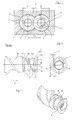
- the screw elements 1 on a frontal profile 2 which is composed of three circular arcs AB, EF and AE.
- the circular arc AB has a diameter corresponding to the outer diameter of the screw D, the circular arc EF a diameter corresponding to the screw core diameter d and the circular arc AE a diameter whose radius corresponds to the axial distance Ax of the two screw elements 1 (see. EP-B-0002131 ).
- the intermeshing screw elements 1 of the twin-screw extruder are mounted against rotation on two parallel, in the same direction rotating shafts 3, which are guided to the screw shafts 3 parallel circular segments 4 of the extruder housing 6, so that two gussets 5 are formed.
- FIGS. 2a to 2c has the two-start screw element 1 three concentric to the shaft axis 7 and arranged at a distance ring section 8.
- the ring sections 8 are provided here, relative to the conveying direction represented by the arrow 9, on the side of the screw element 1 facing the outlet of the extruder, ie, a long screw section 11a is provided in the conveying direction 9, against which the first two ring sections follow 8 two shorter screw sections 11b and 11c and after the third ring section 8 an even shorter screw section 11d connect.
- the distance of the ring sections 8 from one another corresponds to about one third of the screw diameter and the distance of the end face of the screw segment 11 d from the adjacent ring section 8 only about 1/6 D.
- the ring sections 8 are obtained by grooves 12 in the screw element 1.
- the angle ⁇ of the flanks 13 of the recesses 12 to the shaft axis 10 is about 60 degrees.
- the height of the annular gaps 14 between the ring sections 8 and the extruder housing 6 is after Figure 2c about half of the channel depth t, ie half the difference between the core diameter d and the outer diameter of the screw D ( FIG. 1 ).
- the diameter dr of the ring sections 8 thus corresponds approximately to the center distance Ax of the shafts 3 from each other.
- FIGS. 3a to 3c The screw element 1 after FIGS. 3a to 3c is different from that FIGS. 2a to 2c essentially in that, instead of the screw section 11a, a conveying-neutral section 15 is provided, which is formed by a corresponding material removal of the screw block of the screw element 1.
- the screw element 1 after FIGS. 3a to 3c is particularly suitable for an extruder having three or more screw elements arranged in a cavity of an extruder housing along a circle or circular arc with the same central angular distance, which divide the cavity into an inner and outer space.
- material balancing between the inner and the outer frame must take place in such ring extruders.
- the ring sections 8 and the short screw sections 11b, c and d of the screw element after FIGS. 3a to 3c inhibit the flow of product is allowed by the passage 15 a passage from one to the other process space.
- the screw element after FIG. 4 is different from that FIGS. 3a to 3c essentially in that only two ring sections 8 are provided, wherein the one ring section 8 is arranged between the one end face of the screw element 1 and the conveying neutral section 15, and two screw sections 11e and f separated by the second ring section 8 and a further screw section 11g between the end face of the screw element 1 and the ring portion 8 are provided on the portion 15.
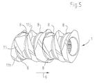
- FIG. 2 a is how in FIG. 2 a through the dashed Line 16 indicated, formed a continuous screw, which is interrupted only by the grooves 12 with the ring sections 8.
- the worm sections 11 h, i, j... between the ring sections 8 are arranged angularly offset with respect to one another in the same direction of rotation.
Landscapes
- Engineering & Computer Science (AREA)
- Mechanical Engineering (AREA)
- Physics & Mathematics (AREA)
- Algebra (AREA)
- General Physics & Mathematics (AREA)
- Mathematical Analysis (AREA)
- Mathematical Optimization (AREA)
- Mathematical Physics (AREA)
- Pure & Applied Mathematics (AREA)
- Extrusion Moulding Of Plastics Or The Like (AREA)
- Processing And Handling Of Plastics And Other Materials For Molding In General (AREA)
Description
Die Erfindung bezieht sich auf einen Extruder zum kontinuierlichen Bearbeiten und/oder Verarbeiten von fließfähigen Stoffen nach dem Oberbegriff des Anspruches 1.The invention relates to an extruder for the continuous processing and / or processing of flowable substances according to the preamble of
Zum kontinuierlichen Bearbeiten, also insbesondere Mischen und Kneten von fließfähigen, also flüssigen, zähflüssigen, plastischen oder teilchenförmigen Stoffen werden in Zweiwellenextrudern sogenannte Knetblöcke verwendet, die aus Wendeltreppenartig versetzt angeordneten Kurvenscheiben bestehen (vgl.
Aus
Out
Aufgabe der Erfindung ist es, die Antriebsenergie des Extruders optimal in eine gleichmäßige Bearbeitung und Behandlung des Stoffes umzusetzen.The object of the invention is to optimally convert the drive energy of the extruder into a uniform processing and treatment of the substance.
Dies wird erfindungsgemäß mit dem in Anspruch 1 gekennzeichneten Extruder erreicht. In den Unteransprüchen sind vorteilhafte Ausgestaltungen der Erfindung wiedergegeben.This is achieved according to the invention with the characterized in
Erfindungsgemäß weist der Extruder wenigstens ein Schneckenelement auf, das mit mehreren Ringabschnitten versehen ist, die konzentrisch oder koaxial zur Schneckenwelle im Abstand voneinander angeordnet und durch Eindrehungen in das Schneckenelement gebildet sind.According to the invention, the extruder has at least one screw element which is provided with a plurality of annular sections, which are arranged concentrically or coaxially to the worm shaft at a distance from each other and formed by grooves in the screw element.
Durch die Schneckenabschnitte des Schneckenelementes zwischen den Ringabschnitten gemäß dem kennzeichnenden Teil des Anspuchs 1, wird zunächst ein Druck aufgebaut, durch den dann der Stoff unter Scherwirkung und Dehnung durch den Ringspalt zwischen Extrudergehäuse und den Ringabschnitten gedrückt und der Druck wieder abgebaut wird. Durch die wiederkehrende Folge: Scherspaltpassage, Druckaufbau, Scherspaltpassage usw. an den Schneckenelementen erfolgt eine definierte Beanspruchung des Stoffes und damit eine gleichmäßige Beanspruchung, ohne den Stoff oder die Schnecke übermäßig zu beanspruchen.By the screw sections of the screw element between the ring sections according to the characterizing part of
Der Ring- und/oder Scherspalt zwischen den Ringabschnitten und den konkaven Kreissegmenten des Extrudergehäuses kann eine unterschiedliche Höhe aufweisen, um entsprechend dem jeweiligen Stoff eine hinreichende Misch- und/oder Knetwirkung zu erzeugen. Der Ringabschnitt kann dazu gegebenenfalls lediglich dem Kerndurchmesser der Schneckenwelle entsprechen. Vorzugsweise weist der Ringspalt jedoch eine Höhe von 10 % bis 90 % der Gangtiefe der Schnecke auf. Besonders bevorzugt ist ein Durchmesser der Ringabschnitte, der etwa dem Achsabstand zweier benachbarter Wellen entspricht.The ring and / or shear gap between the ring sections and the concave circle segments of the extruder housing may have a different height to produce a sufficient mixing and / or kneading effect according to the respective substance. The ring section may optionally only correspond to the core diameter of the worm shaft. However, the annular gap preferably has a height of 10% to 90% of the flight depth of the screw. Particularly preferred is a diameter of the ring sections, which corresponds approximately to the center distance of two adjacent waves.
Bevor der Stoff bei der Passage über den Ring- oder Scherspalt beansprucht wird, muss er durch einen Schneckenabschnitt eine gewisse Förderstrecke transportiert werden, um den erforderlichen Druck aufzubauen. Dazu weisen die Schneckenabschnitte, die zwischen zwei benachbarten Ringabschnitten liegen, im allgemeinen eine Länge von mindestens 1/10, vorzugsweise mindestens 1/5 des Schneckendurchmessers auf. Die Ringabschnitte werden vorzugsweise durch Eindrehungen in das Schneckenelement gebildet. Die Eindrehungen weisen vorzugsweise eine Tiefe von beispielsweise 1/2 oder weniger der Gangtiefe auf. Der Winkel der Flanken der Eindrehungen kann beispielsweise 30 bis 90 Grad betragen. Vorzugsweise werden schräge Eindrehungen durchgeführt, insbesondere mit einem Winkel von etwa 60 Grad zur Wellenachse.Before the substance is subjected to passage through the ring or shear gap, it must be transported through a screw section a certain conveyor line to build up the required pressure. For this purpose, the screw sections, which lie between two adjacent ring sections, generally have a length of at least 1/10, preferably at least 1/5 of the screw diameter. The ring sections are preferably formed by grooves in the screw element. The grooves preferably have a depth of, for example, 1/2 or less of the flight depth. The angle of the flanks of the grooves, for example, be 30 to 90 degrees. Preferably, oblique grooves are performed, in particular with an angle of about 60 degrees to the shaft axis.
Durch Werkstoffabtrag am Schneckenkamm und Flanken kann das Schneckenelement mit weiteren Abschnitten versehen werden. So kann insbesondere ein im wesentlichen förderneutraler Mischabschnitt durch Werkstoffabtrag vorgesehen sein.By removing material on the screw crest and flanks, the screw element can be provided with further sections. Thus, in particular, a substantially promoting neutral mixing section can be provided by material removal.
Damit wird erfindungsgemäß insbesondere für Mehrwellenextruder ein Schneckenelement zur Verfügung gestellt, mit dem die vielfältigsten Ansprüche der Verfahrenstechnik von einem definierten Längsmischen großer Volumina im Deziliterbereich bis zu einem intensiven und nachhaltigen Einwirken im Centi- bis Milliliterbereich erfüllt werden können.Thus, a screw element is provided according to the invention, in particular for multi-screw extruders, with which the most varied requirements of the process technology can be met by a defined longitudinal mixing of large volumes in the deciliters range up to an intensive and lasting effect in the centi to milliliter range.
Nach den Ringspalten kann sich der Schneckengang im gleichen Gangsteigungswinkel fortsetzen. D.h., die Schneckenabschnitte des Schneckenelementes können, abgesehen von den eingedrehten Unterbrechungen im Bereich der Ringabschnitte einen fortlaufenden Schneckengang bilden.After the annular gaps, the flight can continue at the same pitch angle. That is, the screw sections of the screw element can, apart from the screwed-in interruptions in the region of the ring sections form a continuous screw flight.
Durch die Ringabschnitte werden zusätzliche Dispergierflächen gewonnen. Eine wesentliche Dispergierflächenvergrößerung kann zudem dadurch erreicht werden, dass die Schneckenabschnitte zwischen den Ringabschnitten mit gleichem Drehsinn fortschreitend zueinander winkelversetzt angeordnet sind, beispielsweise mit einem Winkelversatz um den halben Gangwinkel. Durch die winkelversetzten Schneckenabschnitte werden treppenartig winkelversetzte Stirnflächen als zusätzliche Dispergierflächen gebildet.Through the ring sections additional dispersing surfaces are obtained. An essential dispersing surface enlargement can also be achieved by arranging the screw sections between the ring sections with the same direction of rotation progressively angularly offset from one another, for example with an angular offset by half the angle of the transition. The angularly offset screw sections form angularly offset end faces as additional dispersing surfaces.
Der erfindungsgemäße Extruder kann lediglich zwei Schneckenwellen aufweisen. Er kann jedoch auch mindestens drei in einem Hohlraum des Extrudergehäuses längs eines Kreises oder Kreisbogens mit gleichem Zentriwinkelabstand angeordnete Wellen aufweisen, wobei das Extrudergehäuse an der radial innen- und außenliegenden Seite des Hohlraumes mit zur Extruderachse parallelen konkaven Kreissegmenten versehen ist, an denen die Schneckenelemente dicht geführt sind, wie beispielsweise in
Nachstehend ist der erfindungsgemäße Extruder anhand der Zeichnung näher erläutert. Darin zeigen:
-
Figur 1 -
Figur 2a bis 2c eine Seitenansicht, perspektivische Ansicht bzw. Ansicht des Stirnprofils einer ersten Ausführungsform des Schneckenelementes; -
Figur 3a bis 3b eine Seitenansicht, perspektivische Ansicht bzw. Ansicht des Stirnprofils einer zweiten Ausführungsform des Schneckenelementes; und -
Figur 4 -
Figur 5
-
FIG. 1 a cross section through a twin-screw extruder with all-round tightly intermeshing screw elements; -
FIGS. 2a to 2c a side view, perspective view or view of the end profile of a first embodiment of the screw element; -
Figure 3a to 3b a side view, perspective view or view of the end profile of a second embodiment of the screw element; and -
FIG. 4 a perspective view of a third embodiment of the screw element; and -
FIG. 5 a perspective view of a fourth embodiment of the screw element
Gemäß
Die ineinander greifenden Schneckenelemente 1 des Zweiwellenextruders sind verdrehsicher auf zwei parallele, gleichsinnig drehende Wellen 3 aufgesteckt, die zu den Schneckenwellen 3 parallelen Kreissegmenten 4 des Extrudergehäuses 6 geführt sind, sodass zwei Zwickel 5 gebildet werden.The intermeshing
Gemäß
Die Ringabschnitte 8 sind hier, bezogen auf die durch den Pfeil 9 dargestellte Förderrichtung, an der dem Auslass des Extruders zugewandten Seite des Schneckenelementes 1 vorgesehen, d.h., es ist in Förderrichtung 9 ein langer Schneckenabschnitt 11a vorgesehen, an den sich nach den ersten beiden Ringabschnitten 8 zwei kürzere Schneckenabschnitte 11b und 11c und nach dem dritten Ringabschnitt 8 ein noch kürzerer Schneckenabschnitt 11d anschließen.The
Während der Schneckenabschnitt 11a etwa dem Schneckendurchmesser D entspricht, entspricht der Abstand der Ringabschnitte 8 voneinander etwa ein Drittel des Schneckendurchmessers und der Abstand der Stirnfläche des Schneckensegmentes 11 d vom benachbarten Ringabschnitt 8 lediglich etwa 1/6 D.While the
Die Ringabschnitte 8 werden durch Eindrehungen 12 in das Schneckenelement 1 erhalten. Der Winkel α der Flanken 13 der Eindrehungen 12 zur Wellenachse 10 beträgt etwa 60 Grad.The
Die Höhe der Ringspalte 14 zwischen den Ringabschnitten 8 und dem Extrudergehäuse 6 beträgt nach
Das Schneckenelement 1 nach
Das Schneckenelement 1 nach
Das Schneckenelement nach
Bei dem Schneckenelement 1 nach
Demgegenüber sind bei der Ausführungsform nach
Claims (9)
- An extruder for the continuous treatment and/or processing of free-flowing substances with at least two parallel shafts (3) rotating in the same direction which are fitted with intermeshing screw elements the end faces of which are delimited by circular arcs (A-B, E-F, A-E) which correspond to the outer diameter (D) of the screw, to the core diameter (d) of the screw and, at most, to the axial distance (Ax) of the screw elements, and which are guided on circular segments (4) of the extruder housing (6) which are parallel to the shafts, characterized in that at least one screw element (1) has a plurality of interspaced concentric annular sections (8) having screw sections (11b, 11c, 11i, 11j ...) between the annular sections (8), wherein the annular sections (8) are formed by turned grooves (12) in the screw element (1).
- An extruder according to claim 1, characterized in that the axial distance of the annular sections (8) of the screw element (1) is not larger than the outer diameter (D) of the screw.
- An extruder according to claim 1 or 2, characterized in that the axial distance of the annular sections (8) of the screw element (1) is at least 1/10 of the screw diameter (D).
- An extruder according to any of the preceding claims, characterized in that the height (h) of the annular gap (14) between the annular sections (8) and the circular segments (4) of the extruder housing (6) corresponds to one fourth to three fourths of the flight depth (t).
- An extruder according to any of the preceding claims, characterized in that the diameter (d) of the annular sections (8) corresponds approximately to the axial distance (Ax) of the shafts (3).
- An extruder according to any of the preceding claims, characterized in that the flanks (13) of the annular sections (8) run at an angle to the shaft axis (7).
- An extruder according to any of the preceding claims, characterized in that the screw sections (11h, i, j ...) between the annular sections (8) are arranged progressively and offset to each other at an angle in the same rotational direction.
- An extruder according to any of claims 1 to 6, characterized in that, except for the interruption in the area of the annular sections (8), the screw sections (11a, b, c ...) of the screw element (1) form a continuous screw flight (16).
- A device according to any of the preceding claims, characterized in that the screw element (1) has in addition at least one feed-neutral section (15).
Applications Claiming Priority (3)
| Application Number | Priority Date | Filing Date | Title |
|---|---|---|---|
| DE10233213A DE10233213B4 (en) | 2002-07-22 | 2002-07-22 | extruder |
| DE10233213 | 2002-07-22 | ||
| PCT/EP2003/005074 WO2004009326A1 (en) | 2002-07-22 | 2003-05-14 | Extruder |
Publications (2)
| Publication Number | Publication Date |
|---|---|
| EP1523403A1 EP1523403A1 (en) | 2005-04-20 |
| EP1523403B1 true EP1523403B1 (en) | 2014-09-24 |
Family
ID=30469027
Family Applications (1)
| Application Number | Title | Priority Date | Filing Date |
|---|---|---|---|
| EP03730036.5A Expired - Lifetime EP1523403B1 (en) | 2002-07-22 | 2003-05-14 | Extruder |
Country Status (6)
| Country | Link |
|---|---|
| US (1) | US7270471B2 (en) |
| EP (1) | EP1523403B1 (en) |
| JP (1) | JP4369366B2 (en) |
| DE (1) | DE10233213B4 (en) |
| ES (1) | ES2523296T3 (en) |
| WO (1) | WO2004009326A1 (en) |
Families Citing this family (22)
| Publication number | Priority date | Publication date | Assignee | Title |
|---|---|---|---|---|
| DE10233213B4 (en) * | 2002-07-22 | 2004-09-09 | 3+Extruder Gmbh | extruder |
| DE10233214B4 (en) * | 2002-07-22 | 2005-01-27 | 3+Extruder Gmbh | Extruder for continuous processing and / or processing of flowable materials |
| DE102004052055B4 (en) * | 2004-10-26 | 2014-11-20 | Blach Verwaltung Gmbh & Co.Kg | extruder |
| DE102005053907B4 (en) * | 2005-11-11 | 2009-05-20 | Blach Verwaltung Gmbh & Co.Kg | Multi-screw extruder |
| EP1832281A1 (en) | 2006-03-10 | 2007-09-12 | Abbott GmbH & Co. KG | Process for producing a solid dispersion of an active ingredient |
| DE102006014692B3 (en) * | 2006-03-28 | 2007-08-02 | Berstorff Gmbh | Kneading assembly for plastic and rubber compounds has two or more discrete kneading stations on a single helical spindle |
| DE102007016346A1 (en) * | 2007-04-03 | 2008-10-09 | Blach Verwaltungs Gmbh & Co. Kg | Multi-shaft extruder apparatus and method of operating the same |
| JP4746014B2 (en) * | 2007-07-09 | 2011-08-10 | 株式会社日本製鋼所 | Melt-kneading devolatilizing extruder |
| WO2009021334A1 (en) * | 2007-08-15 | 2009-02-19 | Ivan Askgaard | Propulsion system and method for a cable ferry |
| DE102008016862C5 (en) * | 2008-04-02 | 2019-12-19 | Blach Verwaltungs Gmbh & Co. Kg | extruder |
| DE102008029304A1 (en) * | 2008-06-20 | 2009-12-24 | Bayer Technology Services Gmbh | Method for producing screw elements |
| US20100052206A1 (en) * | 2008-08-29 | 2010-03-04 | Christopher Lane Kerr | Extrusion Mixing Screw And Method Of Use |
| ES2584514T3 (en) * | 2009-07-16 | 2016-09-28 | Blach Verwaltungs Gmbh & Co. Kg | Extruder |
| DE102009057139A1 (en) * | 2009-12-08 | 2011-06-09 | Bayer Technology Services Gmbh | Process for the construction of corotating, moving bodies in the same direction |
| AT509710B1 (en) | 2010-03-24 | 2011-11-15 | Josef Ing Blach | EXTRUDER |
| JP4829372B1 (en) * | 2010-08-12 | 2011-12-07 | ファナック株式会社 | Screw for material feeding device of injection molding machine |
| US9180511B2 (en) | 2012-04-12 | 2015-11-10 | Rel, Inc. | Thermal isolation for casting articles |
| FR3007685B1 (en) * | 2013-06-27 | 2016-02-05 | Clextral | SCREW ELEMENT FOR AN EXTRUDER BIVIS COROTATIVE, AS WELL AS EXTRUDER BIVIS COROTATIVE CORRESPONDING |
| JP7180244B2 (en) * | 2018-09-27 | 2022-11-30 | セイコーエプソン株式会社 | Plasticizing device |
| CN110901016B (en) * | 2019-11-04 | 2021-09-03 | 大维塑料技术(南京)有限公司 | Screw rod of plastic extruding machine |
| CN118829534A (en) | 2022-03-11 | 2024-10-22 | 科思创德国股份有限公司 | Screw elements with improved mixing effect and pressure build-up |
| EP4458548A1 (en) | 2023-05-04 | 2024-11-06 | Covestro Deutschland AG | Screw elements with improved mixing effect and improved heat transfer and use thereof |
Family Cites Families (25)
| Publication number | Priority date | Publication date | Assignee | Title |
|---|---|---|---|---|
| DE813154C (en) * | 1949-09-29 | 1951-09-06 | Bayer Ag | Mixing and kneading device |
| DE974124C (en) * | 1950-03-08 | 1960-09-22 | Carlo Pasquetti | Screw press for processing thermoplastic materials |
| CA925670A (en) * | 1970-01-28 | 1973-05-08 | P. Fritsch Rudolf | Apparatus for plastifying of particulate synthetic plastics |
| JPS5829733B2 (en) * | 1977-11-19 | 1983-06-24 | 積水化学工業株式会社 | extruder |
| DE2854207C3 (en) | 1978-12-15 | 1984-06-20 | Basf Ag, 6700 Ludwigshafen | Screw extruder for the continuous preparation of plasticizable masses |
| DE2934297A1 (en) * | 1979-08-24 | 1981-03-26 | Eberhard Dipl.-Ing. 7000 Stuttgart Grünschloß | Extruder screw - in which multiple threads in fusion zone have twin flow paths where one has sickle shaped section |
| DD159836A3 (en) * | 1981-05-06 | 1983-04-13 | Dieter Andersch | JAM AND MIXING ELEMENT FOR DOUBLE SCREW EXTRUDERS |
| GB8712545D0 (en) * | 1987-05-28 | 1987-07-01 | Unilever Plc | High shear mixing |
| JPH0262222A (en) * | 1988-08-30 | 1990-03-02 | Mitsubishi Heavy Ind Ltd | Pressure regulator for extruder |
| DE3841728C1 (en) * | 1988-12-10 | 1990-03-01 | Hermann Berstorff Maschinenbau Gmbh, 30627 Hannover | Single or twin-screw extruders for incorporating powdered or fibrous additives into a thermoplastic melt |
| DE3841729C1 (en) * | 1988-12-10 | 1990-03-01 | Hermann Berstorff Maschinenbau Gmbh, 30627 Hannover | Single or twin screw extruders for degassing thermoplastic melts |
| DE3843576A1 (en) * | 1988-12-23 | 1990-07-12 | Jv Kunststoffwerk | METHOD AND DEVICE FOR PRODUCING PLASTIC MOLDED PARTS |
| DE58907012D1 (en) | 1989-10-12 | 1994-03-24 | Josef A Blach | Mixing and kneading device. |
| JPH0677679B2 (en) * | 1991-07-29 | 1994-10-05 | ビーエイチ工業有限会社 | Continuous kneading machine |
| JPH0677680B2 (en) * | 1991-08-16 | 1994-10-05 | ビーエイチ工業有限会社 | Continuous kneading machine |
| JP2986702B2 (en) * | 1995-01-31 | 1999-12-06 | 株式会社日本製鋼所 | Screw for plasticizing apparatus and plasticizing method |
| US5630968A (en) * | 1995-06-07 | 1997-05-20 | The Japan Steel Works, Ltd. | Water-injection foaming devolatilizing method |
| ATE181867T1 (en) * | 1996-02-06 | 1999-07-15 | Josef A Blach | DEVICE FOR CONTINUOUS PROCESSING OF FLOWING MATERIALS |
| DE19847102C1 (en) * | 1998-10-13 | 2000-01-05 | 3 & Extruder Gmbh | Machine for continuously working flowing materials |
| JP4377978B2 (en) * | 1998-11-17 | 2009-12-02 | 住友化学株式会社 | Method for producing the composition |
| JP4670173B2 (en) * | 2000-05-12 | 2011-04-13 | 株式会社デンソー | Extrusion equipment |
| DE10122462C1 (en) * | 2001-05-09 | 2002-10-10 | 3 & Extruder Gmbh | Screw extruder has at least three parallel, intermeshing screws and casing with apertures in its side |
| DE10207145B4 (en) * | 2002-02-20 | 2004-07-15 | Blach, Josef A. | Device for dispersing and melting flowable materials |
| DE10233214B4 (en) * | 2002-07-22 | 2005-01-27 | 3+Extruder Gmbh | Extruder for continuous processing and / or processing of flowable materials |
| DE10233213B4 (en) * | 2002-07-22 | 2004-09-09 | 3+Extruder Gmbh | extruder |
-
2002
- 2002-07-22 DE DE10233213A patent/DE10233213B4/en not_active Expired - Lifetime
-
2003
- 2003-05-14 US US10/503,143 patent/US7270471B2/en not_active Expired - Lifetime
- 2003-05-14 WO PCT/EP2003/005074 patent/WO2004009326A1/en not_active Ceased
- 2003-05-14 JP JP2004522162A patent/JP4369366B2/en not_active Expired - Lifetime
- 2003-05-14 EP EP03730036.5A patent/EP1523403B1/en not_active Expired - Lifetime
- 2003-05-14 ES ES03730036.5T patent/ES2523296T3/en not_active Expired - Lifetime
Also Published As
| Publication number | Publication date |
|---|---|
| ES2523296T3 (en) | 2014-11-24 |
| EP1523403A1 (en) | 2005-04-20 |
| US20050084559A1 (en) | 2005-04-21 |
| DE10233213B4 (en) | 2004-09-09 |
| WO2004009326A1 (en) | 2004-01-29 |
| JP2005533681A (en) | 2005-11-10 |
| US7270471B2 (en) | 2007-09-18 |
| JP4369366B2 (en) | 2009-11-18 |
| DE10233213A1 (en) | 2004-02-19 |
Similar Documents
| Publication | Publication Date | Title |
|---|---|---|
| EP1523403B1 (en) | Extruder | |
| DE4134026C2 (en) | Co-rotating screw kneader | |
| EP1526959B1 (en) | Extruder for the continuous handling and/or processing of free-flowing materials | |
| DE69519431T2 (en) | MULTI-SCREW EXTRUDERS WITH MODULAR MIXING ELEMENTS | |
| AT509710B1 (en) | EXTRUDER | |
| DE102008016862B4 (en) | extruder | |
| CH630285A5 (en) | DEVICE FOR CONTINUOUSLY MIXING FLOWABLE MATERIALS. | |
| EP0346757A2 (en) | Twin screw extruder | |
| DE1502335B2 (en) | SCREW EXTRUSION PRESS FOR THE PROCESSING OF PLASTIC | |
| DE2550969A1 (en) | SCREW MACHINE FOR HOMOGENIZING SOLID, LIQUID AND VISCOSE MATERIALS | |
| EP1829660A2 (en) | Mixer and kneader for plastics | |
| EP3473396A1 (en) | Two-blade worm gear for mixing and kneading machine | |
| EP2272651B1 (en) | Screw machine with dispersive mixing element | |
| DE10114727B4 (en) | Worm element for co-rotating multi-screw extruder | |
| DE2019522C3 (en) | Screw press for thermoplastics and non-crosslinked elastomers | |
| EP1434679B2 (en) | Ring extruder comprising partially capped transport elements in the feeding region | |
| DE2702390A1 (en) | Extruder for thermoplastics - central screw shaft having middle section with multiple short planetary screws inside threaded barrel | |
| DE102012008169A1 (en) | Planetary rolling construction or modular structured extruder for processing plastic material in e.g. food industry for manufacturing brush, has tooth ends exhibiting slant that is more steep than that of slant of flanks to gear diameter | |
| EP3093119A1 (en) | Extruder screw and method for retrofitting the same | |
| EP0490362B1 (en) | High capacity extruder with a constant number of threads in the inlet and the outlet area of a transfer shear element | |
| EP0012795B1 (en) | Screw extruder for processing plastic, rubber or the like | |
| DE2357945C3 (en) | Screw extruder for the continuous processing of plastic masses | |
| EP3253554B1 (en) | Stuffing screw | |
| DE2802125A1 (en) | Multi-screw homogenising extruder - with intermeshing disc section to restrict axial flow | |
| DE102004050810A1 (en) | Single-shaft, continuous mixing and kneading machine |
Legal Events
| Date | Code | Title | Description |
|---|---|---|---|
| PUAI | Public reference made under article 153(3) epc to a published international application that has entered the european phase |
Free format text: ORIGINAL CODE: 0009012 |
|
| 17P | Request for examination filed |
Effective date: 20040207 |
|
| AK | Designated contracting states |
Kind code of ref document: A1 Designated state(s): AT BE BG CH CY CZ DE DK EE ES FI FR GB GR HU IE IT LI LU MC NL PT RO SE SI SK TR |
|
| RAP1 | Party data changed (applicant data changed or rights of an application transferred) |
Owner name: BLACH VERWALTUNGS GMBH & CO. KG |
|
| 17Q | First examination report despatched |
Effective date: 20101228 |
|
| GRAP | Despatch of communication of intention to grant a patent |
Free format text: ORIGINAL CODE: EPIDOSNIGR1 |
|
| INTG | Intention to grant announced |
Effective date: 20140630 |
|
| GRAS | Grant fee paid |
Free format text: ORIGINAL CODE: EPIDOSNIGR3 |
|
| GRAA | (expected) grant |
Free format text: ORIGINAL CODE: 0009210 |
|
| AK | Designated contracting states |
Kind code of ref document: B1 Designated state(s): AT BE BG CH CY CZ DE DK EE ES FI FR GB GR HU IE IT LI LU MC NL PT RO SE SI SK TR |
|
| REG | Reference to a national code |
Ref country code: GB Ref legal event code: FG4D Free format text: NOT ENGLISH |
|
| REG | Reference to a national code |
Ref country code: CH Ref legal event code: EP |
|
| REG | Reference to a national code |
Ref country code: AT Ref legal event code: REF Ref document number: 688404 Country of ref document: AT Kind code of ref document: T Effective date: 20141015 |
|
| REG | Reference to a national code |
Ref country code: IE Ref legal event code: FG4D Free format text: LANGUAGE OF EP DOCUMENT: GERMAN |
|
| REG | Reference to a national code |
Ref country code: DE Ref legal event code: R096 Ref document number: 50315137 Country of ref document: DE Effective date: 20141106 |
|
| REG | Reference to a national code |
Ref country code: ES Ref legal event code: FG2A Ref document number: 2523296 Country of ref document: ES Kind code of ref document: T3 Effective date: 20141124 |
|
| PG25 | Lapsed in a contracting state [announced via postgrant information from national office to epo] |
Ref country code: SE Free format text: LAPSE BECAUSE OF FAILURE TO SUBMIT A TRANSLATION OF THE DESCRIPTION OR TO PAY THE FEE WITHIN THE PRESCRIBED TIME-LIMIT Effective date: 20140924 Ref country code: FI Free format text: LAPSE BECAUSE OF FAILURE TO SUBMIT A TRANSLATION OF THE DESCRIPTION OR TO PAY THE FEE WITHIN THE PRESCRIBED TIME-LIMIT Effective date: 20140924 Ref country code: GR Free format text: LAPSE BECAUSE OF FAILURE TO SUBMIT A TRANSLATION OF THE DESCRIPTION OR TO PAY THE FEE WITHIN THE PRESCRIBED TIME-LIMIT Effective date: 20141225 |
|
| REG | Reference to a national code |
Ref country code: CH Ref legal event code: NV Representative=s name: KLOTER AND KOHLI RECHTSANWAELTE, CH |
|
| REG | Reference to a national code |
Ref country code: NL Ref legal event code: VDEP Effective date: 20140924 |
|
| PG25 | Lapsed in a contracting state [announced via postgrant information from national office to epo] |
Ref country code: CY Free format text: LAPSE BECAUSE OF FAILURE TO SUBMIT A TRANSLATION OF THE DESCRIPTION OR TO PAY THE FEE WITHIN THE PRESCRIBED TIME-LIMIT Effective date: 20140924 |
|
| PG25 | Lapsed in a contracting state [announced via postgrant information from national office to epo] |
Ref country code: NL Free format text: LAPSE BECAUSE OF FAILURE TO SUBMIT A TRANSLATION OF THE DESCRIPTION OR TO PAY THE FEE WITHIN THE PRESCRIBED TIME-LIMIT Effective date: 20140924 |
|
| PG25 | Lapsed in a contracting state [announced via postgrant information from national office to epo] |
Ref country code: EE Free format text: LAPSE BECAUSE OF FAILURE TO SUBMIT A TRANSLATION OF THE DESCRIPTION OR TO PAY THE FEE WITHIN THE PRESCRIBED TIME-LIMIT Effective date: 20140924 Ref country code: CZ Free format text: LAPSE BECAUSE OF FAILURE TO SUBMIT A TRANSLATION OF THE DESCRIPTION OR TO PAY THE FEE WITHIN THE PRESCRIBED TIME-LIMIT Effective date: 20140924 Ref country code: SK Free format text: LAPSE BECAUSE OF FAILURE TO SUBMIT A TRANSLATION OF THE DESCRIPTION OR TO PAY THE FEE WITHIN THE PRESCRIBED TIME-LIMIT Effective date: 20140924 Ref country code: PT Free format text: LAPSE BECAUSE OF FAILURE TO SUBMIT A TRANSLATION OF THE DESCRIPTION OR TO PAY THE FEE WITHIN THE PRESCRIBED TIME-LIMIT Effective date: 20150126 Ref country code: RO Free format text: LAPSE BECAUSE OF FAILURE TO SUBMIT A TRANSLATION OF THE DESCRIPTION OR TO PAY THE FEE WITHIN THE PRESCRIBED TIME-LIMIT Effective date: 20140924 |
|
| REG | Reference to a national code |
Ref country code: DE Ref legal event code: R097 Ref document number: 50315137 Country of ref document: DE |
|
| PG25 | Lapsed in a contracting state [announced via postgrant information from national office to epo] |
Ref country code: DK Free format text: LAPSE BECAUSE OF FAILURE TO SUBMIT A TRANSLATION OF THE DESCRIPTION OR TO PAY THE FEE WITHIN THE PRESCRIBED TIME-LIMIT Effective date: 20140924 |
|
| PLBE | No opposition filed within time limit |
Free format text: ORIGINAL CODE: 0009261 |
|
| STAA | Information on the status of an ep patent application or granted ep patent |
Free format text: STATUS: NO OPPOSITION FILED WITHIN TIME LIMIT |
|
| 26N | No opposition filed |
Effective date: 20150625 |
|
| REG | Reference to a national code |
Ref country code: CH Ref legal event code: PCAR Free format text: NEW ADDRESS: FORCHSTRASSE 30 POSTFACH, 8032 ZUERICH (CH) |
|
| GBPC | Gb: european patent ceased through non-payment of renewal fee |
Effective date: 20150514 |
|
| PG25 | Lapsed in a contracting state [announced via postgrant information from national office to epo] |
Ref country code: MC Free format text: LAPSE BECAUSE OF FAILURE TO SUBMIT A TRANSLATION OF THE DESCRIPTION OR TO PAY THE FEE WITHIN THE PRESCRIBED TIME-LIMIT Effective date: 20140924 Ref country code: LU Free format text: LAPSE BECAUSE OF FAILURE TO SUBMIT A TRANSLATION OF THE DESCRIPTION OR TO PAY THE FEE WITHIN THE PRESCRIBED TIME-LIMIT Effective date: 20150514 |
|
| REG | Reference to a national code |
Ref country code: IE Ref legal event code: MM4A |
|
| PG25 | Lapsed in a contracting state [announced via postgrant information from national office to epo] |
Ref country code: SI Free format text: LAPSE BECAUSE OF FAILURE TO SUBMIT A TRANSLATION OF THE DESCRIPTION OR TO PAY THE FEE WITHIN THE PRESCRIBED TIME-LIMIT Effective date: 20140924 |
|
| REG | Reference to a national code |
Ref country code: FR Ref legal event code: PLFP Year of fee payment: 14 |
|
| PG25 | Lapsed in a contracting state [announced via postgrant information from national office to epo] |
Ref country code: GB Free format text: LAPSE BECAUSE OF NON-PAYMENT OF DUE FEES Effective date: 20150514 Ref country code: IE Free format text: LAPSE BECAUSE OF NON-PAYMENT OF DUE FEES Effective date: 20150514 |
|
| PG25 | Lapsed in a contracting state [announced via postgrant information from national office to epo] |
Ref country code: HU Free format text: LAPSE BECAUSE OF FAILURE TO SUBMIT A TRANSLATION OF THE DESCRIPTION OR TO PAY THE FEE WITHIN THE PRESCRIBED TIME-LIMIT; INVALID AB INITIO Effective date: 20030514 Ref country code: BG Free format text: LAPSE BECAUSE OF FAILURE TO SUBMIT A TRANSLATION OF THE DESCRIPTION OR TO PAY THE FEE WITHIN THE PRESCRIBED TIME-LIMIT Effective date: 20140924 |
|
| REG | Reference to a national code |
Ref country code: FR Ref legal event code: PLFP Year of fee payment: 15 |
|
| PG25 | Lapsed in a contracting state [announced via postgrant information from national office to epo] |
Ref country code: BE Free format text: LAPSE BECAUSE OF NON-PAYMENT OF DUE FEES Effective date: 20150531 |
|
| PG25 | Lapsed in a contracting state [announced via postgrant information from national office to epo] |
Ref country code: TR Free format text: LAPSE BECAUSE OF FAILURE TO SUBMIT A TRANSLATION OF THE DESCRIPTION OR TO PAY THE FEE WITHIN THE PRESCRIBED TIME-LIMIT Effective date: 20140924 |
|
| REG | Reference to a national code |
Ref country code: CH Ref legal event code: PFA Owner name: BLACH VERWALTUNGS GMBH AND CO. KG, DE Free format text: FORMER OWNER: BLACH VERWALTUNGS GMBH AND CO. KG, DE |
|
| REG | Reference to a national code |
Ref country code: FR Ref legal event code: PLFP Year of fee payment: 16 |
|
| REG | Reference to a national code |
Ref country code: DE Ref legal event code: R079 Ref document number: 50315137 Country of ref document: DE Free format text: PREVIOUS MAIN CLASS: B29C0047400000 Ipc: B29C0048400000 |
|
| PGFP | Annual fee paid to national office [announced via postgrant information from national office to epo] |
Ref country code: FR Payment date: 20220331 Year of fee payment: 20 |
|
| PGFP | Annual fee paid to national office [announced via postgrant information from national office to epo] |
Ref country code: IT Payment date: 20220524 Year of fee payment: 20 Ref country code: ES Payment date: 20220601 Year of fee payment: 20 Ref country code: DE Payment date: 20220524 Year of fee payment: 20 |
|
| PGFP | Annual fee paid to national office [announced via postgrant information from national office to epo] |
Ref country code: CH Payment date: 20220524 Year of fee payment: 20 Ref country code: AT Payment date: 20220524 Year of fee payment: 20 |
|
| REG | Reference to a national code |
Ref country code: DE Ref legal event code: R071 Ref document number: 50315137 Country of ref document: DE |
|
| REG | Reference to a national code |
Ref country code: CH Ref legal event code: PL |
|
| REG | Reference to a national code |
Ref country code: ES Ref legal event code: FD2A Effective date: 20230526 |
|
| REG | Reference to a national code |
Ref country code: AT Ref legal event code: MK07 Ref document number: 688404 Country of ref document: AT Kind code of ref document: T Effective date: 20230514 |
|
| PG25 | Lapsed in a contracting state [announced via postgrant information from national office to epo] |
Ref country code: ES Free format text: LAPSE BECAUSE OF EXPIRATION OF PROTECTION Effective date: 20230515 |