EP1522996B1 - Verfahren zur Aufzeichnung von Indentifikationsinformationen, Vorrichtung dafür und Informationsaufzeichnungsmedium - Google Patents
Verfahren zur Aufzeichnung von Indentifikationsinformationen, Vorrichtung dafür und Informationsaufzeichnungsmedium Download PDFInfo
- Publication number
- EP1522996B1 EP1522996B1 EP04022262A EP04022262A EP1522996B1 EP 1522996 B1 EP1522996 B1 EP 1522996B1 EP 04022262 A EP04022262 A EP 04022262A EP 04022262 A EP04022262 A EP 04022262A EP 1522996 B1 EP1522996 B1 EP 1522996B1
- Authority
- EP
- European Patent Office
- Prior art keywords
- recording
- layer
- information
- medium
- recorded
- Prior art date
- Legal status (The legal status is an assumption and is not a legal conclusion. Google has not performed a legal analysis and makes no representation as to the accuracy of the status listed.)
- Expired - Lifetime
Links
- 238000000034 method Methods 0.000 title claims description 57
- 239000000758 substrate Substances 0.000 claims abstract description 22
- 230000031700 light absorption Effects 0.000 claims description 23
- 239000000463 material Substances 0.000 claims description 17
- 238000004519 manufacturing process Methods 0.000 claims description 7
- 238000010438 heat treatment Methods 0.000 claims description 4
- 230000008569 process Effects 0.000 claims description 4
- 230000001131 transforming effect Effects 0.000 claims description 2
- 239000010410 layer Substances 0.000 abstract description 185
- 230000003287 optical effect Effects 0.000 abstract description 76
- 239000002356 single layer Substances 0.000 abstract description 18
- 239000002365 multiple layer Substances 0.000 abstract description 6
- 238000010586 diagram Methods 0.000 description 23
- 239000000975 dye Substances 0.000 description 10
- 229910052681 coesite Inorganic materials 0.000 description 9
- 229910052906 cristobalite Inorganic materials 0.000 description 9
- 239000000377 silicon dioxide Substances 0.000 description 9
- VYPSYNLAJGMNEJ-UHFFFAOYSA-N silicon dioxide Inorganic materials O=[Si]=O VYPSYNLAJGMNEJ-UHFFFAOYSA-N 0.000 description 9
- 229910052682 stishovite Inorganic materials 0.000 description 9
- 229910052905 tridymite Inorganic materials 0.000 description 9
- 230000000694 effects Effects 0.000 description 8
- 238000002474 experimental method Methods 0.000 description 8
- 238000004544 sputter deposition Methods 0.000 description 8
- 230000008859 change Effects 0.000 description 6
- 238000007796 conventional method Methods 0.000 description 6
- 229920000515 polycarbonate Polymers 0.000 description 6
- 239000004417 polycarbonate Substances 0.000 description 6
- 230000007246 mechanism Effects 0.000 description 5
- 239000000853 adhesive Substances 0.000 description 4
- 230000001070 adhesive effect Effects 0.000 description 4
- 239000011347 resin Substances 0.000 description 4
- 229920005989 resin Polymers 0.000 description 4
- 229910000838 Al alloy Inorganic materials 0.000 description 3
- 230000007423 decrease Effects 0.000 description 3
- 238000010521 absorption reaction Methods 0.000 description 2
- 230000008901 benefit Effects 0.000 description 2
- 230000003247 decreasing effect Effects 0.000 description 2
- 230000002349 favourable effect Effects 0.000 description 2
- 230000009466 transformation Effects 0.000 description 2
- 235000005811 Viola adunca Nutrition 0.000 description 1
- 240000009038 Viola odorata Species 0.000 description 1
- 235000013487 Viola odorata Nutrition 0.000 description 1
- 235000002254 Viola papilionacea Nutrition 0.000 description 1
- 230000004075 alteration Effects 0.000 description 1
- 238000005520 cutting process Methods 0.000 description 1
- 238000009826 distribution Methods 0.000 description 1
- 239000002355 dual-layer Substances 0.000 description 1
- 230000001678 irradiating effect Effects 0.000 description 1
- 201000010065 polycystic ovary syndrome Diseases 0.000 description 1
- 230000005855 radiation Effects 0.000 description 1
- 238000004528 spin coating Methods 0.000 description 1
- 238000000844 transformation Methods 0.000 description 1
- 230000000007 visual effect Effects 0.000 description 1
Images


Classifications
-
- G—PHYSICS
- G11—INFORMATION STORAGE
- G11B—INFORMATION STORAGE BASED ON RELATIVE MOVEMENT BETWEEN RECORD CARRIER AND TRANSDUCER
- G11B7/00—Recording or reproducing by optical means, e.g. recording using a thermal beam of optical radiation by modifying optical properties or the physical structure, reproducing using an optical beam at lower power by sensing optical properties; Record carriers therefor
- G11B7/004—Recording, reproducing or erasing methods; Read, write or erase circuits therefor
- G11B7/0045—Recording
- G11B7/00454—Recording involving phase-change effects
-
- G—PHYSICS
- G11—INFORMATION STORAGE
- G11B—INFORMATION STORAGE BASED ON RELATIVE MOVEMENT BETWEEN RECORD CARRIER AND TRANSDUCER
- G11B7/00—Recording or reproducing by optical means, e.g. recording using a thermal beam of optical radiation by modifying optical properties or the physical structure, reproducing using an optical beam at lower power by sensing optical properties; Record carriers therefor
- G11B7/24—Record carriers characterised by shape, structure or physical properties, or by the selection of the material
- G11B7/2403—Layers; Shape, structure or physical properties thereof
-
- G—PHYSICS
- G11—INFORMATION STORAGE
- G11B—INFORMATION STORAGE BASED ON RELATIVE MOVEMENT BETWEEN RECORD CARRIER AND TRANSDUCER
- G11B7/00—Recording or reproducing by optical means, e.g. recording using a thermal beam of optical radiation by modifying optical properties or the physical structure, reproducing using an optical beam at lower power by sensing optical properties; Record carriers therefor
- G11B7/24—Record carriers characterised by shape, structure or physical properties, or by the selection of the material
- G11B7/26—Apparatus or processes specially adapted for the manufacture of record carriers
- G11B7/268—Post-production operations, e.g. initialising phase-change recording layers, checking for defects
-
- G—PHYSICS
- G11—INFORMATION STORAGE
- G11B—INFORMATION STORAGE BASED ON RELATIVE MOVEMENT BETWEEN RECORD CARRIER AND TRANSDUCER
- G11B7/00—Recording or reproducing by optical means, e.g. recording using a thermal beam of optical radiation by modifying optical properties or the physical structure, reproducing using an optical beam at lower power by sensing optical properties; Record carriers therefor
- G11B2007/0003—Recording, reproducing or erasing systems characterised by the structure or type of the carrier
- G11B2007/0009—Recording, reproducing or erasing systems characterised by the structure or type of the carrier for carriers having data stored in three dimensions, e.g. volume storage
- G11B2007/0013—Recording, reproducing or erasing systems characterised by the structure or type of the carrier for carriers having data stored in three dimensions, e.g. volume storage for carriers having multiple discrete layers
-
- G—PHYSICS
- G11—INFORMATION STORAGE
- G11B—INFORMATION STORAGE BASED ON RELATIVE MOVEMENT BETWEEN RECORD CARRIER AND TRANSDUCER
- G11B7/00—Recording or reproducing by optical means, e.g. recording using a thermal beam of optical radiation by modifying optical properties or the physical structure, reproducing using an optical beam at lower power by sensing optical properties; Record carriers therefor
- G11B7/007—Arrangement of the information on the record carrier, e.g. form of tracks, actual track shape, e.g. wobbled, or cross-section, e.g. v-shaped; Sequential information structures, e.g. sectoring or header formats within a track
- G11B7/00736—Auxiliary data, e.g. lead-in, lead-out, Power Calibration Area [PCA], Burst Cutting Area [BCA], control information
-
- G—PHYSICS
- G11—INFORMATION STORAGE
- G11B—INFORMATION STORAGE BASED ON RELATIVE MOVEMENT BETWEEN RECORD CARRIER AND TRANSDUCER
- G11B7/00—Recording or reproducing by optical means, e.g. recording using a thermal beam of optical radiation by modifying optical properties or the physical structure, reproducing using an optical beam at lower power by sensing optical properties; Record carriers therefor
- G11B7/24—Record carriers characterised by shape, structure or physical properties, or by the selection of the material
- G11B7/2403—Layers; Shape, structure or physical properties thereof
- G11B7/24035—Recording layers
- G11B7/24038—Multiple laminated recording layers
-
- G—PHYSICS
- G11—INFORMATION STORAGE
- G11B—INFORMATION STORAGE BASED ON RELATIVE MOVEMENT BETWEEN RECORD CARRIER AND TRANSDUCER
- G11B7/00—Recording or reproducing by optical means, e.g. recording using a thermal beam of optical radiation by modifying optical properties or the physical structure, reproducing using an optical beam at lower power by sensing optical properties; Record carriers therefor
- G11B7/24—Record carriers characterised by shape, structure or physical properties, or by the selection of the material
- G11B7/24094—Indication parts or information parts for identification
Definitions
- the present invention relates to an information recording medium, a method of recording information thereon, and equipment thereof.
- the following technique is generally used: preparing a write-once type area (Burst Cutting Area, hereinafter referred to as a "BCA") on which a barcode is overwritten on a pit of a read-only optical recording medium, and then during manufacturing of the optical recording medium, recording identification data (ID data) which is different in each optical recording medium and recording an encryption key or a reproducing key if necessary, on the BCA area.
- BCA Write-once type area
- a write-once optical information recording medium having an information layer which can record a signal only once and also including a plurality of recording layers, and a rewritable optical information recording medium having an information layer which can rewrite an information signal a number of times have been developed.
- various kinds of media have appeared (hereinafter, referred to as a "single-layer optical disk” including both the write-once type and the rewritable type).
- an optical disk having a plurality of recording layers which enables the recording of high-capacity information such as Hi-Vision images has been put into practical use (hereinafter, referred to as a "multiple-layer optical disk” including both the write-once type and the rewritable type).
- the identification data of a medium is recorded by applying a laser beam from the side at which information is recorded and reproduced. Therefore, the conditions for recording the identification data on a recording layer farthest from the laser incident side in a multiple-layer optical disk need to be greatly changed compared to those of a single-layer optical disk, because the effect of a front-side layer should be taken into consideration. This can complicate BCA producing equipment.
- recording materials which generally have a high wavelength dependency such as organic dyes, because the recording conditions can vary due to even a slight change in recording wavelength or in optical properties of the dye material, stable recording has been a difficult task.
- the recording medium of reference 1 is a rewritable phase-changeable recording medium
- the recording mode during processing of the BCA is the same as the mode for deleting information in a usual recording process. In this instance, because the medium has fairly low temperature in the recording mode, it is rare that the recording layer is damaged during the processing.
- a recording mode during processing of the BCA of a write-once phase-changeable recording medium is the same as the mode for recording information in a usual recording process. In this situation, a high temperature is necessary.
- the recording is performed using a large laser spot, which means the recording is performed by supplying an energy that is several hundred times higher than for usual recording. Thus, a hot section is produced over a significantly large area on the recording layer, and the recording layer is damaged. This causes the problem of decreasing the signal quality when reproducing the BCA.
- the European Patent Application EP 1 308 938 A1 describes a number of different optical disk apparatuses that record both data and visual images by irradiating a laser beam from a pickup onto an optical disk are disclosed.
- a scanning section scans the laser beam relative to the optical disk.
- a recording control section controls the scanning section to effect recording of data on-a recordable face.
- a drawing control section is-provided for controlling the pickup and the scanning section to effect drawing of a visible image on either the recordable face or on a different thermally sensitive face of the optical disk. Therefore separate apparatus to print labels presenting content information are not required.
- An object of the present invention is to solve the conventional problems, and to provide a method for easily and stably recording identification data of a medium, even when using the write-once recording medium or having a recording material with a high wavelength dependency, as well as equipment thereof and an optical disk having a BCA pattern thereon.
- the identification data can be recorded under the same recording conditions, because the path of the laser beam from the entrance point to the recording point of the identification data is equal.
- the medium preferably has a light absorption layer between the surface of the side opposite to where user data is recorded/reproduced and the information recording layer, and the identification data is preferably recorded on the information recording layer by heat propagation caused by heating the light absorption layer using the laser beam.
- the identification data is stably recorded by reducing the deformation of the information recording layer caused by heat.
- the light absorption layer of the medium used in the method of recording information of the present invention functions as a reflecting layer when recording or reproducing user data.
- a width of the focusing spot of the laser beam which is applied to the light absorption layer during the recording is preferably narrower than that of a shortest mark of the identification data.
- the laser beam is defocused on the light absorption layer
- the information recording equipment of the present invention includes a focusing control unit which causes the beam to defocus.
- a range of focusing is preferably between -2 and -10 or +2 and +10 times longer than the focusing depth.
- an information recording medium used in the method of the present invention preferably has an information recording layer composed of a phase-changeable recording material.
- the identification data can be recorded at high quality by using the difference of a reflecting ratio between a crystalline state and a non-crystalline state.
- the information recording layer is composed of a write-once phase-changeable recording material, and the identification data is recorded by changing a non-crystalline phase of the information recording layer to a crystalline phase.
- the identification data is stably recorded by reducing the deformation of the information recording layer caused by heat.
- the information recording layer is preferably composed of an organic dye recording material.
- the organic dye recording material will record heat generated from the light absorption layer, and the slight light absorption characteristics of the dye material will not be affected, the information can be stably recorded.
- a BCA pattern can be formed easily and stably, regardless of whether . using a single-layer or a multiple-layer optical disk and even when using recording materials which generally have a high wavelength dependency.
- Fig. 1 is a cross-sectional diagram showing an optical disk 5 having a single information recording layer which is used in the method of recording information of the embodiment of the present invention.
- reference numeral 11a is a front-side dielectric layer
- reference numeral 11c is a back-side dielectric layer
- reference numeral 11b is a recording layer
- reference numeral 11d is a reflecting layer
- reference numeral 1 is a substrate
- reference numeral 2 is a cover layer.
- the single-layer optical disk 5 was formed by the following procedure.
- the reflecting layer 11d made of Al alloy with thickness 40 nm, a ZnS-SiO 2 back-end dielectric layer 11c with thickness 30 nm, a Te-O-Pd recording layer 11b with thickness 20 nm and a ZnS-SiO 2 front-side dielectric layer 11a with thickness 40 nm were formed in this order using a vacuum sputtering method. Then, the transparent cover layer 2 with thickness 0.1 mm made of polycarbonate was adhered using an adhesive, not shown in the figure.
- the reflecting layer 11d also functions as a light absorption layer.
- a laser beam 4 for recording identification data of a medium was applied from the side of the substrate 1, and user data was recorded by applying the laser from the side of the cover layer 2.
- Fig. 2 is a cross-sectional diagram showing an optical disk 6 having two information recording layers which was used in the method of recording information of the embodiment of the present invention.
- reference numeral 12a is a front-side dielectric layer of a second layer
- reference numeral 12c is a back-side dielectric layer of the second layer
- reference numeral 12b is a recording layer of the second layer
- reference numeral 12d is a reflecting layer of the second layer
- reference numeral 1 is the substrate
- reference numeral 3 is an intermediate layer
- reference numeral 2b is a cover layer.
- the double-layer optical disk 6 was formed by the following procedures. The same as the procedure for forming the single-layer optical disk, on the transparent substrate 1, the reflecting layer 11d, the back-end dielectric layer 11c, the recording layer 11b and the front-side dielectric layer 11a were formed in this order using the vacuum sputtering method.
- the intermediate layer 3 of thickness 25 ⁇ m made of UV setting resin was formed.
- the reflecting layer made of Al alloy of the second layer 12d with thickness 10 nm, the ZnS-SiO 2 back-side dielectric layer of the second layer 12c with thickness 15 nm, the Te-O-Pd recording layer of the second layer 12b with thickness 10 nm and the ZnS-SiO 2 front-side dielectric layer of the second layer 12a with thickness 20 nm were formed in this order using the vacuum sputtering method.
- the transparent cover layer 2b made of polycarbonate with thickness 0.075 mm was adhered using an adhesive, not shown in the figure.
- the laser beam 4 for recording identification data of a medium was applied from the side of the substrate 1, and user data was recorded by applying the laser from the side of the cover layer 2.
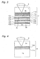
- Fig. 3 is a cross-sectional diagram showing an optical disk 7 having four information recording layers which is used in the method of recording information of the embodiment of the present invention.
- reference numeral 13a is a front-side dielectric layer of a second layer
- reference numeral 13c is a back-side dielectric layer of the second layer
- reference numeral 13b is a recording layer of the second layer
- reference numeral 14a is a front-side dielectric layer of a third layer
- reference numeral 14c is a back-side dielectric layer of the third layer
- reference numeral 14b is a recording layer of the third layer
- reference numeral 15a is a front-side dielectric layer of a fourth layer
- reference numeral 15c is a back-side dielectric layer of the fourth layer
- reference numeral 15b is a recording layer of the fourth layer
- reference numeral 1 is the substrate
- reference numerals 3b, 3c and 3d are intermediate layers
- reference numeral 2c is a cover layer.
- the quadruple-layer optical disk 7 was formed by the following procedures. The same as the procedure for forming the single-layer optical disk, on the transparent substrate 1, the reflecting layer 11d, the back-side dielectric layer 11c, the recording layer 11b and the front-side dielectric layer 11a were formed in this order by using the vacuum sputtering method. Then, the intermediate layer 3b with thickness 15 ⁇ m made of UV setting resin was formed.
- the ZnS-SiO 2 back-side dielectric layer of the second layer 13c with thickness 10 nm, the Te-O-Pd recording layer of the second layer 13b with thickness 15 nm and the ZnS-SiO 2 front-side dielectric layer of the second layer 13a with thickness 20 nm were formed in this order using the vacuum sputtering method. Then, the intermediate layer 3c with thickness 15 ⁇ m made of UV setting resin was formed.
- the ZnS-SiO 2 back-side dielectric layer of the third layer 14c with thickness 5 nm, the Te-O-Pd recording layer of the third layer 14b with thickness 10 nm and the front-side dielectric layer of the third layer 14a with thickness 15 nm were formed in this order using the vacuum sputtering method. Further, the intermediate layer 3d with thickness 15 ⁇ m made of UV setting resin was formed.
- the ZnS-SiO 2 back-side dielectric layer of the fourth layer 15c with thickness 5 nm, the Te-O-Pd recording layer of the fourth layer 15b with thickness 10 nm and the ZnS-SiO 2 front-side dielectric layer of the fourth layer 15a with thickness 15 nm were formed in this order using the vacuum sputtering method. Additionally, the transparent cover layer 2c made of polycarbonate with thickness 0.06 mm was adhered using an adhesive, not shown in the figure.
- the laser beam 4 for recording identification data of a medium was applied from the side of the substrate 1, and user data was recorded by applying the laser from the side of the cover layer 2.
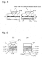
- Fig. 4 is a cross-sectional diagram showing a coat-type optical disk 8 which is used in the method of recording information of the embodiment of the present invention.
- reference numeral 16b is a recording layer
- reference numeral 16d is a reflecting layer
- reference numeral 1b is a coat-type substrate
- reference numeral 2d is a dummy substrate.
- the coat-type optical disk 8 was formed by the following procedures. On the transparent coat-type substrate 1b made of polycarbonate with thickness 0.6 mm and having a tracking groove, an azo organic dye was coated to an average thickness of 100 nm using a spin coating method, and then the reflecting layer made of Al alloy 16d with thickness 60 nm was formed using the vacuum sputtering method. Additionally, the dummy substrate 2d made of polycarbonate with thickness 0.6 mm was adhered using an adhesive, not shown in the figure.
- the laser beam 4 for recording identification data of a medium was applied from the side of the dummy substrate 2d
- the laser beam for recording user data was applied from the side of the coat-type substrate 1b.
- Fig. 5 is a diagram showing an example of the method of recording information of the embodiment of the present invention. Note that, for easy understanding, parts of the structural components are omitted.
- the identification data of a medium are signals, the signals being in accordance with each production number of each disk, and the signals are recorded as a barcode on part of a lead-in area of a disk.
- the incident side of the laser beam for recording identification data on the single-layer optical disk 5 and the double-layer optical disk 6 is the side opposite to the substrate 1 where user data is recorded. From this structure, even in the double-layer optical disk 6, although the identification data is recorded on the recording layer of a first layer 11b, the recording is not affected by the recording layer of a second layer 12b and the like. Therefore, in the double-layer optical disk 6, identification data of a medium can be recorded under the same conditions as the single-layer optical disk 5.
- Fig. 12 is a diagram showing an example of a conventional method of recording information for comparison.
- the incident sides of the laser beam for recording identification data on the single-layer optical disk 105 and the double-layer optical disk 106 are the sides of the cover layers 102 and 102b, which are the same as for recording the user data.
- the identification data is recorded on a recording layer of a first layer 111b, and the recording is affected by the recording layer of a second layer 112b and the like. Therefore, in the double-layer optical disk 106, identification data needs to be recorded under conditions different from that of the single-layer optical disk 105.
- Fig. 6 is an explanatory diagram showing a recording mechanism of the embodiment of the present invention.
- reference letter (b) shows a conventional method of recording identification data of a medium. Because a laser beam 121a directly focuses on and heats the recording layer 111b, the layer 111b gets heat damaged, and the shape of a recording mark 122a is changed.
- Reference letter (a) shows an indirect heat recording method of the present invention.
- a laser beam 21 b for recording the identification data heats the reflecting layer 11d, which is also a light absorption layer, by heat conduction or heat radiation.
- An advantage of the method is that the recording layer does not receive a drastic heat change, and it is difficult to cause physical damage to the recording layer or the substrate.
- power density decreases and the advantage further improves.
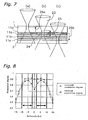
- Fig. 7 is an explanatory diagram showing a recording using a defocused beam (hereinafter referred to as a defocus recording) of the embodiment of the present invention.
- reference letter (b) shows a situation in which the laser focuses on the reflecting layer 11d.
- Reference numeral 23 is a laser beam for recording identification data of a medium
- reference numeral 24 is a heated portion of the reflecting layer
- reference numeral 25 is the focusing depth.
- Reference letter (a) shows a situation in which the laser defocuses at the front-side of the disk, reference numeral 26a therein shows the amount of defocus at the front-side.
- Reference letter (c) shows a situation in which the laser defocuses at the back-side of the disk, reference numeral 26b therein shows the amount of defocus at the back-side.
- a heated portion of the reflecting layer 24 in (b) is highly focused.
- ⁇ s ⁇ ⁇ NA 2
- ⁇ is wavelength of the laser and NA is numerical aperture of the lens.
- Fig. 8 shows the effects of defocusing the beam of the embodiment of the present invention.
- a double-layer medium is used as a sample, and the laser incident side is the side opposite to the surface where the user data is recorded.
- the minimum modulation degree without a defocus (defocus 0) is 0.73; however, the modulation degree improves when defocus increases.
- the amount of defocus is less than -10 ⁇ s or over +10 ⁇ s, a suitable modulation degree can not be obtained because the energy diffuses excessively and the temperature does not rise enough during the recording. From the results, the amount of defocus showing particularly favorable properties ranged between -2 ⁇ s and -10 ⁇ s or +2 ⁇ s and +10 ⁇ s.
- the following methods can also be feasible, such as decreasing NA of the lens and intentionally causing aberration of the lens.
- the size (width) of the focusing spot of the laser beam needs to be narrower than the size (width) of the shortest mark of the identification data.
- the reason is that, because information is indirectly recorded on the recording layer by heat propagation, the recording mark tends to be larger, and this effect needs to be reduced.
- the recording method of the present invention because information is indirectly recorded by heating the light absorption layer, the light absorption property of the recording material of the recording layer can be neglected.
- heat recording becomes feasible regardless of whether it is with or without absorption at the recording wavelength.
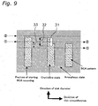
- Fig. 9 is an explanatory diagram showing an example of the method of recording information of the embodiment of the present invention.
- reference numeral 31 is a focusing spot of the laser beam
- reference numeral 32 is a length in the direction of the diameter of the focusing spot
- reference numeral 33 is the travel distance of an optical pickup per disk rotation.
- the recording is performed by transforming an amorphous state into a crystalline state using the laser focusing spot 31 which is longer in the radial direction. Then a BCA pattern is completed by repeating the recording, each time adding a portion of the BCA pattern which is equal to the length of the travel distance of the optical pickup per disk rotation 33.
- Fig. 10 is a diagram showing a reproducing signal of identification data of a medium.
- reference numeral 41 is an unrecorded output
- reference numeral 42 is the maximum modulation degree showing the depth of a recorded mark when the depth of an unrecorded output 41 is defined as 1
- 43 is the minimum value of the modulation degree.
- a pickup for recording/reproducing user data is used again.
- the quality of a reproducing signal is favorable when values of the degree 42 and the degree 43 are large, and also a difference between both the degrees is small.
- the signal qualities when recording and reproducing the identification data of a medium are shown in Table 1.
- a laser used for the recording had a wavelength of 810 nm, the length in the direction of the diameter of the focusing spot was 48 ⁇ m, NA in the circumferential direction of the disk was 0.5, the radial travel distance per disk rotation was 6 ⁇ m, the length of the recorded mark in the circumferential direction of the disk was 17 ⁇ m and the linear velocity was approximately 6 m/sec.
- the laser wavelength of the reproducing pickup was 405 nm, NA was 0.85 and reproducing power was 0.35 mW.
- Example of the present invention 5 Back 0 1900 0.92 0.70 Good 6 Back 0 1900 0.91 0.73 Good 7 Back 0 1900 0.91 0.70 Good 8 Back 0 2400 0.70 0.63 Good 2
- Example of the present invention 5 Back -5 2000 0.90 0.87 Very good 6 Back -5 2000 0.92 0.89 Very good 3
- Example of the present invention 5 Back +5 2000 0.91 0.85 Very good 6 Back +5 2000 0.92 0.89
- Example of conventional method 5 Front 0 1100 0.93 0.39 Bad 6 Front 0 1900 0.94 0.42 Bad 7 Front 0 2800 0.87 0.41 Bad
- Experiment No. 1 shows results without the defocusing and when the identification data was recorded from the side opposite (a back-side) to where user data is recorded.
- Experiment No. 2 shows results in which the recording was performed by setting a relative distance between a focusing lens for recording and an optical disk as an additional 5 ⁇ s (a defocus) further away than the relative distance of Experiment No. 1.
- Experiment No. 3 shows results in which the recording was performed by setting the relative distance as 5 ⁇ s (a defocus) closer than the relative distance of Experiment No. 1.
- Experiment No. 4 shows the results of using a conventional method in which the identification data is recorded from the side (the front-side) at which user data is recorded.
- the recording power was different in the single-layer disk, the double-layer disk and the quadruple-layer disk.
- the minimum modulation degree was small at approximately 0.4, and the difference between the minimum and maximum degree was large.
- the recording power was the same in the single-layer disk, the double-layer disk and the quadruple-layer disk.
- the minimum modulation degree was 0.6 or more, and the difference between the minimum and maximum degree was smaller than that of the conventional example. In the coat-type medium, the difference was small.
- defocusing was performed, the difference between the minimum and maximum modulation degree was further reduced, and a stable recording of the identification data was achieved.
- the laser beam for recording identification data of a medium on an optical disk is applied from the opposite side of the substrate to where user data is recorded. From this structure, even in a multiple-layer optical disk, the identification data can be recorded under the same recording conditions as a single-layer optical disk because the disk is not affected by a second or subsequent recording layer.
- the recording on the recording layer is performed through the reflecting layer, transformation of the recording layer caused by a drastic temperature change is reduced and stable recording becomes feasible.
- by defocusing the laser beam onto the recording layer within a given range drastic temperature change is reduced and stable recording is further feasible.
- the organic dye recording material records heat generated from the light absorption layer and is not affected by the optical absorption properties of the dye, the information can be stably recorded.
- Fig. 11 is a cross-sectional diagram showing information recording equipment of the present invention.
- reference numeral 51 is an optical pickup for recording identification data of a medium
- reference numeral 52 is a turn table
- reference numeral 53 is a centering mechanism
- reference numeral 54 is a motor
- reference numeral 55 is a focusing control device.
- a side of the optical disk 5 for recording user data is fixed to the turn table 52 by a method not shown in the figure, and the disk rotates at a predetermined speed using the motor 54.
- the identification data of the medium is recorded by applying a laser beam from the optical pickup 51 onto the reflecting layer side of the optical disk 5.
- the optical pickup 51 is moved by a feed mechanism not shown in the figure, and the recorded area increases in a radial direction, then the BCA is completed.
- the information recording equipment of the present invention has a centering mechanism 53 which corrects the center position at an inner zone on the opposite side of the disk where the laser beam for recording identification data enters. Therefore, when the optical pickup 51 from which the laser is applied vertically downward is used (for safety reasons), because the centering can be performed at the opposite side to where the optical pickup operates, information recording equipment which is superior for mass-production is achieved.
- the disk 5 can be fixed on the turn table 52 using air suction.
- the equipment of the present invention has a focusing control device 55, and the amount of focus can be set up to ⁇ 10 times longer than the focusing depth. Because transformations of the recording layer and the substrate caused by a drastic heat change during the recording can be reduced by adjusting the power density of the laser spot, the identification data can be recorded favorably and stably.
- identification data of a medium can be recorded easily and stably, and the method is useful for recording a BCA pattern on an optical disk and the like.
- the method can be applied to an optical tape and an optical card, for example.
Landscapes
- Engineering & Computer Science (AREA)
- Manufacturing & Machinery (AREA)
- Optical Recording Or Reproduction (AREA)
- Optical Record Carriers And Manufacture Thereof (AREA)
- Information Retrieval, Db Structures And Fs Structures Therefor (AREA)
- Indexing, Searching, Synchronizing, And The Amount Of Synchronization Travel Of Record Carriers (AREA)
Claims (14)
- Verfahren zum Aufzeichnen von Information auf einem Medium (5; 6) mit einer Informationsaufzeichnungsschicht (11b, 12b), wobei das Verfahren die folgen Schritte umfasst:Aufzeichnen von Identifikationsdaten eines Mediums (5; 6) auf einem scheibenförmigen Informationsaufzeichnungsmedium (5; 6) durch Anwenden eines Laserstrahls (4) von einer Seite, die einer Seite gegenüberliegt, auf der Nutzerdaten aufgezeichnet/wiedergegeben werden,dadurch gekennzeichnet, dass die Identifikationsdaten so aufgezeichnet werden, dass die Identifikationsdaten durch Anwendung eines Laserstrahls (4) zum Aufzeichnen/wiedergeben von Nutzerdaten von derjenigen Seite, auf der Nutzerdaten aufgezeichnet/wiedergegeben werden, wiedergebbar ist.
- Verfahren zum Aufzeichnen von Information nach Anspruch 1, wobei das Medium (5; 6) eine Mehrzahl von Informationsaufzeichnungsschichten (11b, 12b) umfasst.
- Verfahren zum Aufzeichnen von Information nach Anspruch 1 oder 2, wobei das Medium (5; 6) eine Lichtabsorptionsschicht (11d, 12d) zwischen einer Oberfläche der Seite, die der Seite gegenüberliegt, auf der Nutzerdaten aufgezeichnet/wiedergegeben werden, und der Informationsaufzeichnungsschicht (11b, 12b) umfasst; und
wobei die Identifikationsdaten auf der Informationsaufzeichnungsschicht (11b, 12b) indirekt durch Wärmeausbreitung, die durch Erwärmen der Lichtabsorptionsschicht (11d, 12d) mittels des Laserstrahls (4) verursacht wird, aufgezeichnet werden. - Verfahren zum Aufzeichnen von Information nach Anspruch 3, wobei die Lichtabsorptionsschicht (11d, 12d) des Mediums (5: 6) als eine reflektierende Schicht dient, wenn Nutzerdaten aufgezeichnet oder wiedergegeben werden.
- Verfahren zum Aufzeichnen von Information nach Anspruch 3 oder 4, wobei eine Breite eines Fokussierungsspots des Laserstrahls (4), der während des Aufzeichnens auf die Lichtabsorptionsschicht (11d, 12d) angewendet wird, schmaler als die Breite einer kürzesten Markierung der Identifikationsdaten ist.
- Verfahren zum Aufzeichnen von Information nach einem der Ansprüche 3 bis 5, wobei der Laserstrahl (4) auf die Lichtabsorptionsschicht (11d, 12d) defokussiert ist.
- Verfahren zum Aufzeichnen von Information nach Anspruch 6, wobei ein Defokussierungsbereich zwischen zwei- und zehnmal länger als eine Fokussierungstiefe ist.
- Verfahren zum Aufzeichnen von Information nach einem der Ansprüche 1 bis 7, wobei die Informationsaufzeichnungsschicht (11b, 12b) aus einem phasenveränderlichen Aufzeichnungsmaterial besteht.
- Verfahren zum Aufzeichnen von Information nach Anspruch 8, wobei die Informationsaufzeichnungsschicht (11b, 12b) aus einem einmal beschreibbaren phasenveränderlichen Aufzeichnungsmaterial besteht: und
die Identifikationsdaten durch Transformieren einer nichtkristallinen Phase der Informationsaufzeichnungsschicht (11b, 12b) in eine kristalline Phase aufgezeichnet werden. - Verfahren zum Aufzeichnen von Informationen nach einem der Ansprüche 1 bis 7, wobei die Informationsaufzeichnungsschicht (11b, 12b) aus einem Aufzeichnungsmaterial mit einem organischen Farbstoff gebildet wird.
- Verfahren zum Herstellen eines Informationsaufzeichnungsmediums (5; 6), wobei das Verfahren die folgenden Schritte umfasst:Bilden einer Informationsaufzeichnungsschicht (11b, 12b) auf einem scheibenförmigen Substrat (1); undAufzeichnen von Identifikationsdaten eines Mediums (5; 6) gemäß dem Verfahren nach Anspruch 1.
- Verfahren zum Herstellen eines Informationsaufzeichnungsmediums (5; 6) nach Anspruch 11, wobei eine Mehrzahl von Informationsaufzeichnungsschichten (11 b, 12b) während des Bildungsvorgangs gebildet werden.
- Verfahren zum Herstellen eines Informationsaufzeichnungsmediums (5; 6) nach Anspruch 11 oder 12, wobei das Verfahren des Weiteren die folgenden Schritte umfasst:Bilden einer Lichtabsorptionsschicht (11d. 12d) zwischen einer Oberfläche der Seite, die der Seite gegenüberliegt, auf der Nutzerdaten aufzeichnet/wiedergegeben werden, und der Informationsaufzeichnungsschicht (11b, 12b); undwobei die Identifikationsdaten des Mediums (5; 6) auf der Informationsaufzeichnungsschicht (11b, 12b) während des Aufzeichnungsvorgangs indirekt durch Wärmeausbreitung, die durch Erwärmen der Lichtabsorptionsschicht (11d. 12d) mittels des Laserstrahls (4) verursacht wird, aufgezeichnet werden.
- Verfahren zum Herstellen eines Informationsaufzeichnungsmediums (5; 6) nach Anspruch 13, wobei die Lichtabsorptionsschicht (11d. 12d) des Mediums (5; 6) als eine reflektierende Schicht dient, wenn Nutzerdaten aufgezeichnet/wiedergegeben werden.
Applications Claiming Priority (2)
| Application Number | Priority Date | Filing Date | Title |
|---|---|---|---|
| JP2003349420 | 2003-10-08 | ||
| JP2003349420 | 2003-10-08 |
Publications (3)
| Publication Number | Publication Date |
|---|---|
| EP1522996A2 EP1522996A2 (de) | 2005-04-13 |
| EP1522996A3 EP1522996A3 (de) | 2008-02-27 |
| EP1522996B1 true EP1522996B1 (de) | 2011-03-30 |
Family
ID=34309237
Family Applications (1)
| Application Number | Title | Priority Date | Filing Date |
|---|---|---|---|
| EP04022262A Expired - Lifetime EP1522996B1 (de) | 2003-10-08 | 2004-09-18 | Verfahren zur Aufzeichnung von Indentifikationsinformationen, Vorrichtung dafür und Informationsaufzeichnungsmedium |
Country Status (7)
| Country | Link |
|---|---|
| US (1) | US7830779B2 (de) |
| EP (1) | EP1522996B1 (de) |
| KR (1) | KR101083199B1 (de) |
| CN (1) | CN100380457C (de) |
| AT (1) | ATE504058T1 (de) |
| DE (1) | DE602004032002D1 (de) |
| TW (1) | TWI350530B (de) |
Families Citing this family (8)
| Publication number | Priority date | Publication date | Assignee | Title |
|---|---|---|---|---|
| DE602004032002D1 (de) | 2003-10-08 | 2011-05-12 | Panasonic Corp | Verfahren zur Aufzeichnung von Indentifikationsinformationen, Vorrichtung dafür und Informationsaufzeichnungsmedium |
| JP4276516B2 (ja) * | 2003-10-20 | 2009-06-10 | パイオニア株式会社 | 多層光記録媒体および光ピックアップ装置 |
| MXPA04012240A (es) * | 2003-12-08 | 2005-09-30 | Matsushita Electric Ind Co Ltd | Medio optico de grabacion de informacion y metodo para grabar marcas de tipo codigo de barras. |
| JP2006338718A (ja) * | 2005-05-31 | 2006-12-14 | Nec Corp | 光ディスク媒体および光ディスク装置 |
| DE602006013487D1 (de) | 2005-09-30 | 2010-05-20 | Nec Corp | Optisches informationsaufzeichnungsmedium, bca-informationsrekorder und bca-informationsaufzeichnungsverfahren |
| JP2007323773A (ja) * | 2006-06-02 | 2007-12-13 | Toshiba Corp | 光ディスク、情報記録方法、情報再生方法、およびディスクドライブ |
| JP4720768B2 (ja) * | 2007-03-28 | 2011-07-13 | 株式会社日立製作所 | ディスク状媒体及びディスク装置 |
| JPWO2010032348A1 (ja) * | 2008-09-18 | 2012-02-02 | パナソニック株式会社 | 情報記録媒体及びその製造方法 |
Family Cites Families (22)
| Publication number | Priority date | Publication date | Assignee | Title |
|---|---|---|---|---|
| JPS62149050A (ja) | 1985-12-23 | 1987-07-03 | Toshiba Corp | 光記録媒体 |
| US5726969A (en) * | 1994-12-28 | 1998-03-10 | Matsushita Electric Industrial Co., Ltd. | Optical recording medium having dual information surfaces |
| DE69614580T2 (de) * | 1995-10-09 | 2002-04-11 | Matsushita Electric Industrial Co., Ltd. | Wiedergabegerät für optische Platten |
| CN1311457C (zh) * | 1996-12-19 | 2007-04-18 | 松下电器产业株式会社 | 光盘再生装置 |
| US5946286A (en) * | 1997-03-20 | 1999-08-31 | Imation Corp. | Customized graphics for dual layer optical discs |
| ES2341600T3 (es) * | 1997-06-16 | 2010-06-22 | Thomson Consumer Electronics, Inc. | Identificacion de informacion de programa en un soporte de registro. |
| JP3676548B2 (ja) | 1997-08-25 | 2005-07-27 | 太陽誘電株式会社 | 光情報媒体の記録再生方法 |
| US7304937B1 (en) * | 1998-06-16 | 2007-12-04 | Thomson Licensing | Identification of program information on a recording medium |
| EP1038294A2 (de) * | 1998-06-18 | 2000-09-27 | Koninklijke Philips Electronics N.V. | Wiederbeschreibbares optisches informationmsmedium |
| DE19923542A1 (de) | 1999-05-21 | 2001-01-18 | Thomson Brandt Gmbh | Optischer Aufzeichnungsträger |
| WO2001006502A1 (en) * | 1999-07-15 | 2001-01-25 | Matsushita Electric Industrial Co., Ltd. | Optical recording medium and method for recording optical recording medium |
| JP2001243636A (ja) | 1999-07-15 | 2001-09-07 | Matsushita Electric Ind Co Ltd | 光記録媒体および光記録媒体の記録方法 |
| JP2002117576A (ja) | 2000-10-03 | 2002-04-19 | Tdk Corp | 光記録媒体および光学的情報記録方法 |
| JPWO2002037483A1 (ja) | 2000-11-06 | 2004-03-11 | 松下電器産業株式会社 | 光記録媒体、光記録媒体製造方法、光記録媒体製造装置、プログラム、および媒体 |
| KR100788646B1 (ko) * | 2001-08-09 | 2007-12-26 | 삼성전자주식회사 | 광디스크의 bca 코드 기록방법 |
| JP3956756B2 (ja) * | 2001-10-31 | 2007-08-08 | ヤマハ株式会社 | 光ディスク記録装置 |
| JP2003168242A (ja) * | 2001-11-29 | 2003-06-13 | Tdk Corp | 追記型光記録媒体の反射率の調整方法及び追記型光記録媒体 |
| US6778205B2 (en) * | 2002-02-28 | 2004-08-17 | Hewlett-Packard Development Company, L.P. | Methods and apparatuses for forming visible labels on objects using a writable optical disc drive |
| JP3873784B2 (ja) * | 2002-03-13 | 2007-01-24 | ヤマハ株式会社 | 光ディスク装置 |
| EP1463042B1 (de) * | 2003-02-21 | 2006-04-19 | Nec Corporation | Träger für optische Datenaufzeichnung und Gerät für optische Datenaufzeichnung und Wiedergabe |
| JP4255758B2 (ja) | 2003-06-19 | 2009-04-15 | 日立コンピュータ機器株式会社 | バーコード記録装置及びバーコード記録方法 |
| DE602004032002D1 (de) | 2003-10-08 | 2011-05-12 | Panasonic Corp | Verfahren zur Aufzeichnung von Indentifikationsinformationen, Vorrichtung dafür und Informationsaufzeichnungsmedium |
-
2004
- 2004-09-18 DE DE602004032002T patent/DE602004032002D1/de not_active Expired - Lifetime
- 2004-09-18 AT AT04022262T patent/ATE504058T1/de not_active IP Right Cessation
- 2004-09-18 EP EP04022262A patent/EP1522996B1/de not_active Expired - Lifetime
- 2004-09-22 TW TW093128705A patent/TWI350530B/zh not_active IP Right Cessation
- 2004-09-23 US US10/947,255 patent/US7830779B2/en active Active
- 2004-09-30 CN CNB2004100857247A patent/CN100380457C/zh not_active Expired - Lifetime
- 2004-10-08 KR KR1020040080586A patent/KR101083199B1/ko not_active Expired - Lifetime
Non-Patent Citations (3)
| Title |
|---|
| ISAO SATOH: "Next-Generation Blue-Violet Laser Multi-Layer Optical Recording", XP002203753 * |
| KITAURA H ET AL: "Multi-layer write-once media with Te-O-Pd films utilizing a violet laser", PROCEEDINGS OF SPIE, CONF- PHYSICS OF SEMICONDUCTOR DEVICES - 20011211 TO 20011215 - DELHI, SPIE, US LNKD- DOI:10.1117/12.453382, vol. 4342, 22 April 2001 (2001-04-22), pages 340 - 347, XP007901934, ISSN: 0277-786X * |
| UNO M ET AL: "DUAL-LAYER WRITE-ONCE MEDIA FOR 1X-4X SPEED RECORDING BASED ON BLU-RAY DISC FORMAT", PROCEEDINGS OF SPIE, CONF- PHYSICS OF SEMICONDUCTOR DEVICES - 20011211 TO 20011215 - DELHI, SPIE, US LNKD- DOI:10.1117/12.532520, vol. 5069, no. 1, 14 May 2003 (2003-05-14), pages 82 - 89, XP001193864, ISSN: 0277-786X * |
Also Published As
| Publication number | Publication date |
|---|---|
| DE602004032002D1 (de) | 2011-05-12 |
| TWI350530B (en) | 2011-10-11 |
| KR20050033868A (ko) | 2005-04-13 |
| ATE504058T1 (de) | 2011-04-15 |
| US7830779B2 (en) | 2010-11-09 |
| KR101083199B1 (ko) | 2011-11-11 |
| EP1522996A2 (de) | 2005-04-13 |
| CN1606073A (zh) | 2005-04-13 |
| EP1522996A3 (de) | 2008-02-27 |
| TW200518066A (en) | 2005-06-01 |
| US20050078594A1 (en) | 2005-04-14 |
| CN100380457C (zh) | 2008-04-09 |
Similar Documents
| Publication | Publication Date | Title |
|---|---|---|
| US6226239B1 (en) | Optical information recording and reproducing apparatus for multiple layer recording medium | |
| CA2410779C (en) | Optical information recording medium, optical information recording method, and optical information recording apparatus | |
| JP3250989B2 (ja) | 光学情報記録媒体、その記録再生方法、その製造法及び光学情報記録再生装置 | |
| JP2928292B2 (ja) | 光学情報記録部材および光学情報記録再生装置 | |
| US7801000B2 (en) | Recording/reading method for an optical recording medium using an irradiating a laser beam | |
| US6990053B2 (en) | Method and apparatus for initializing optical recording media | |
| WO1999000794A1 (en) | Optical recording medium and optical disk device | |
| JP4161716B2 (ja) | 光学記録媒体および光ディスク装置 | |
| RU2279723C2 (ru) | Оптический носитель записи, способ изготовления оптического носителя записи и способ воспроизведения информации с оптического носителя записи | |
| KR101029189B1 (ko) | 광 기록 매체 및 그 제조 방법, 광 기록 방법, 광 재생방법, 광 기록 장치, 광 재생 장치 및 광 기록 재생 장치 | |
| CN1327416C (zh) | 光学记录介质以及光学记录介质的记录/读取方法和装置 | |
| EP1522996B1 (de) | Verfahren zur Aufzeichnung von Indentifikationsinformationen, Vorrichtung dafür und Informationsaufzeichnungsmedium | |
| JP2001250265A (ja) | 多層光ディスク及びその初期化方法 | |
| JP4108553B2 (ja) | 光情報記録媒体及び光情報記録装置 | |
| CN100377237C (zh) | 光信息记录介质 | |
| US20090290476A1 (en) | Optical information recording medium, optical information recording/reproducing apparatus, and method of manufacturing optical information recording medium | |
| JP4308117B2 (ja) | 情報記録方法と装置及び情報記録媒体 | |
| JP2007141289A (ja) | 光情報記録再生装置及び光情報記録媒体 | |
| WO2003025918A1 (en) | Recording medium recording method and recording medium | |
| JP2006209898A (ja) | 光学情報記録媒体及び光学情報再生装置 | |
| JP4161537B2 (ja) | 光記録媒体の製造方法 | |
| JP2003217186A (ja) | 相変化型光ディスクの初期化方法および初期化装置 | |
| US20050232126A1 (en) | Optical data storage medium and use of such medium | |
| JPH0935331A (ja) | 光情報記録媒体及びその再生方法 | |
| JPH08263879A (ja) | 光記録媒体及び光記録再生方法 |
Legal Events
| Date | Code | Title | Description |
|---|---|---|---|
| PUAI | Public reference made under article 153(3) epc to a published international application that has entered the european phase |
Free format text: ORIGINAL CODE: 0009012 |
|
| AK | Designated contracting states |
Kind code of ref document: A2 Designated state(s): AT BE BG CH CY CZ DE DK EE ES FI FR GB GR HU IE IT LI LU MC NL PL PT RO SE SI SK TR |
|
| AX | Request for extension of the european patent |
Extension state: AL HR LT LV MK |
|
| PUAL | Search report despatched |
Free format text: ORIGINAL CODE: 0009013 |
|
| AK | Designated contracting states |
Kind code of ref document: A3 Designated state(s): AT BE BG CH CY CZ DE DK EE ES FI FR GB GR HU IE IT LI LU MC NL PL PT RO SE SI SK TR |
|
| AX | Request for extension of the european patent |
Extension state: AL HR LT LV MK |
|
| RIC1 | Information provided on ipc code assigned before grant |
Ipc: G11B 7/24 20060101ALI20080118BHEP Ipc: G11B 7/26 20060101ALI20080118BHEP Ipc: G11B 7/0045 20060101ALI20080118BHEP Ipc: G11B 7/007 20060101AFI20050204BHEP |
|
| 17P | Request for examination filed |
Effective date: 20080528 |
|
| AKX | Designation fees paid |
Designated state(s): AT BE BG CH CY CZ DE DK EE ES FI FR GB GR HU IE IT LI LU MC NL PL PT RO SE SI SK TR |
|
| RAP1 | Party data changed (applicant data changed or rights of an application transferred) |
Owner name: PANASONIC CORPORATION |
|
| 17Q | First examination report despatched |
Effective date: 20081029 |
|
| GRAP | Despatch of communication of intention to grant a patent |
Free format text: ORIGINAL CODE: EPIDOSNIGR1 |
|
| GRAC | Information related to communication of intention to grant a patent modified |
Free format text: ORIGINAL CODE: EPIDOSCIGR1 |
|
| GRAS | Grant fee paid |
Free format text: ORIGINAL CODE: EPIDOSNIGR3 |
|
| GRAA | (expected) grant |
Free format text: ORIGINAL CODE: 0009210 |
|
| AK | Designated contracting states |
Kind code of ref document: B1 Designated state(s): AT BE BG CH CY CZ DE DK EE ES FI FR GB GR HU IE IT LI LU MC NL PL PT RO SE SI SK TR |
|
| REG | Reference to a national code |
Ref country code: GB Ref legal event code: FG4D |
|
| REG | Reference to a national code |
Ref country code: CH Ref legal event code: EP |
|
| REG | Reference to a national code |
Ref country code: IE Ref legal event code: FG4D |
|
| REF | Corresponds to: |
Ref document number: 602004032002 Country of ref document: DE Date of ref document: 20110512 Kind code of ref document: P |
|
| REG | Reference to a national code |
Ref country code: DE Ref legal event code: R096 Ref document number: 602004032002 Country of ref document: DE Effective date: 20110512 |
|
| REG | Reference to a national code |
Ref country code: NL Ref legal event code: VDEP Effective date: 20110330 |
|
| PG25 | Lapsed in a contracting state [announced via postgrant information from national office to epo] |
Ref country code: GR Free format text: LAPSE BECAUSE OF FAILURE TO SUBMIT A TRANSLATION OF THE DESCRIPTION OR TO PAY THE FEE WITHIN THE PRESCRIBED TIME-LIMIT Effective date: 20110701 Ref country code: SE Free format text: LAPSE BECAUSE OF FAILURE TO SUBMIT A TRANSLATION OF THE DESCRIPTION OR TO PAY THE FEE WITHIN THE PRESCRIBED TIME-LIMIT Effective date: 20110330 |
|
| PG25 | Lapsed in a contracting state [announced via postgrant information from national office to epo] |
Ref country code: AT Free format text: LAPSE BECAUSE OF FAILURE TO SUBMIT A TRANSLATION OF THE DESCRIPTION OR TO PAY THE FEE WITHIN THE PRESCRIBED TIME-LIMIT Effective date: 20110330 Ref country code: SI Free format text: LAPSE BECAUSE OF FAILURE TO SUBMIT A TRANSLATION OF THE DESCRIPTION OR TO PAY THE FEE WITHIN THE PRESCRIBED TIME-LIMIT Effective date: 20110330 Ref country code: CY Free format text: LAPSE BECAUSE OF FAILURE TO SUBMIT A TRANSLATION OF THE DESCRIPTION OR TO PAY THE FEE WITHIN THE PRESCRIBED TIME-LIMIT Effective date: 20110330 Ref country code: FI Free format text: LAPSE BECAUSE OF FAILURE TO SUBMIT A TRANSLATION OF THE DESCRIPTION OR TO PAY THE FEE WITHIN THE PRESCRIBED TIME-LIMIT Effective date: 20110330 |
|
| PG25 | Lapsed in a contracting state [announced via postgrant information from national office to epo] |
Ref country code: BE Free format text: LAPSE BECAUSE OF FAILURE TO SUBMIT A TRANSLATION OF THE DESCRIPTION OR TO PAY THE FEE WITHIN THE PRESCRIBED TIME-LIMIT Effective date: 20110330 |
|
| PG25 | Lapsed in a contracting state [announced via postgrant information from national office to epo] |
Ref country code: PT Free format text: LAPSE BECAUSE OF FAILURE TO SUBMIT A TRANSLATION OF THE DESCRIPTION OR TO PAY THE FEE WITHIN THE PRESCRIBED TIME-LIMIT Effective date: 20110801 Ref country code: EE Free format text: LAPSE BECAUSE OF FAILURE TO SUBMIT A TRANSLATION OF THE DESCRIPTION OR TO PAY THE FEE WITHIN THE PRESCRIBED TIME-LIMIT Effective date: 20110330 |
|
| PG25 | Lapsed in a contracting state [announced via postgrant information from national office to epo] |
Ref country code: ES Free format text: LAPSE BECAUSE OF FAILURE TO SUBMIT A TRANSLATION OF THE DESCRIPTION OR TO PAY THE FEE WITHIN THE PRESCRIBED TIME-LIMIT Effective date: 20110711 Ref country code: RO Free format text: LAPSE BECAUSE OF FAILURE TO SUBMIT A TRANSLATION OF THE DESCRIPTION OR TO PAY THE FEE WITHIN THE PRESCRIBED TIME-LIMIT Effective date: 20110330 Ref country code: CZ Free format text: LAPSE BECAUSE OF FAILURE TO SUBMIT A TRANSLATION OF THE DESCRIPTION OR TO PAY THE FEE WITHIN THE PRESCRIBED TIME-LIMIT Effective date: 20110330 Ref country code: SK Free format text: LAPSE BECAUSE OF FAILURE TO SUBMIT A TRANSLATION OF THE DESCRIPTION OR TO PAY THE FEE WITHIN THE PRESCRIBED TIME-LIMIT Effective date: 20110330 |
|
| PG25 | Lapsed in a contracting state [announced via postgrant information from national office to epo] |
Ref country code: NL Free format text: LAPSE BECAUSE OF FAILURE TO SUBMIT A TRANSLATION OF THE DESCRIPTION OR TO PAY THE FEE WITHIN THE PRESCRIBED TIME-LIMIT Effective date: 20110330 |
|
| PLBE | No opposition filed within time limit |
Free format text: ORIGINAL CODE: 0009261 |
|
| STAA | Information on the status of an ep patent application or granted ep patent |
Free format text: STATUS: NO OPPOSITION FILED WITHIN TIME LIMIT |
|
| PG25 | Lapsed in a contracting state [announced via postgrant information from national office to epo] |
Ref country code: PL Free format text: LAPSE BECAUSE OF FAILURE TO SUBMIT A TRANSLATION OF THE DESCRIPTION OR TO PAY THE FEE WITHIN THE PRESCRIBED TIME-LIMIT Effective date: 20110330 Ref country code: DK Free format text: LAPSE BECAUSE OF FAILURE TO SUBMIT A TRANSLATION OF THE DESCRIPTION OR TO PAY THE FEE WITHIN THE PRESCRIBED TIME-LIMIT Effective date: 20110330 |
|
| 26N | No opposition filed |
Effective date: 20120102 |
|
| REG | Reference to a national code |
Ref country code: DE Ref legal event code: R097 Ref document number: 602004032002 Country of ref document: DE Effective date: 20120102 |
|
| PG25 | Lapsed in a contracting state [announced via postgrant information from national office to epo] |
Ref country code: MC Free format text: LAPSE BECAUSE OF NON-PAYMENT OF DUE FEES Effective date: 20110930 |
|
| REG | Reference to a national code |
Ref country code: CH Ref legal event code: PL |
|
| PG25 | Lapsed in a contracting state [announced via postgrant information from national office to epo] |
Ref country code: IT Free format text: LAPSE BECAUSE OF FAILURE TO SUBMIT A TRANSLATION OF THE DESCRIPTION OR TO PAY THE FEE WITHIN THE PRESCRIBED TIME-LIMIT Effective date: 20110330 |
|
| REG | Reference to a national code |
Ref country code: IE Ref legal event code: MM4A |
|
| PG25 | Lapsed in a contracting state [announced via postgrant information from national office to epo] |
Ref country code: LI Free format text: LAPSE BECAUSE OF NON-PAYMENT OF DUE FEES Effective date: 20110930 Ref country code: CH Free format text: LAPSE BECAUSE OF NON-PAYMENT OF DUE FEES Effective date: 20110930 Ref country code: IE Free format text: LAPSE BECAUSE OF NON-PAYMENT OF DUE FEES Effective date: 20110918 |
|
| PG25 | Lapsed in a contracting state [announced via postgrant information from national office to epo] |
Ref country code: LU Free format text: LAPSE BECAUSE OF NON-PAYMENT OF DUE FEES Effective date: 20110918 |
|
| PG25 | Lapsed in a contracting state [announced via postgrant information from national office to epo] |
Ref country code: BG Free format text: LAPSE BECAUSE OF FAILURE TO SUBMIT A TRANSLATION OF THE DESCRIPTION OR TO PAY THE FEE WITHIN THE PRESCRIBED TIME-LIMIT Effective date: 20110630 |
|
| PG25 | Lapsed in a contracting state [announced via postgrant information from national office to epo] |
Ref country code: TR Free format text: LAPSE BECAUSE OF FAILURE TO SUBMIT A TRANSLATION OF THE DESCRIPTION OR TO PAY THE FEE WITHIN THE PRESCRIBED TIME-LIMIT Effective date: 20110330 |
|
| PG25 | Lapsed in a contracting state [announced via postgrant information from national office to epo] |
Ref country code: HU Free format text: LAPSE BECAUSE OF FAILURE TO SUBMIT A TRANSLATION OF THE DESCRIPTION OR TO PAY THE FEE WITHIN THE PRESCRIBED TIME-LIMIT Effective date: 20110330 |
|
| REG | Reference to a national code |
Ref country code: FR Ref legal event code: PLFP Year of fee payment: 13 |
|
| REG | Reference to a national code |
Ref country code: FR Ref legal event code: PLFP Year of fee payment: 14 |
|
| REG | Reference to a national code |
Ref country code: FR Ref legal event code: PLFP Year of fee payment: 15 |
|
| PGFP | Annual fee paid to national office [announced via postgrant information from national office to epo] |
Ref country code: GB Payment date: 20230727 Year of fee payment: 20 |
|
| PGFP | Annual fee paid to national office [announced via postgrant information from national office to epo] |
Ref country code: FR Payment date: 20230710 Year of fee payment: 20 Ref country code: DE Payment date: 20230726 Year of fee payment: 20 |
|
| REG | Reference to a national code |
Ref country code: DE Ref legal event code: R071 Ref document number: 602004032002 Country of ref document: DE |
|
| REG | Reference to a national code |
Ref country code: GB Ref legal event code: PE20 Expiry date: 20240917 |
|
| PG25 | Lapsed in a contracting state [announced via postgrant information from national office to epo] |
Ref country code: GB Free format text: LAPSE BECAUSE OF EXPIRATION OF PROTECTION Effective date: 20240917 |
|
| PG25 | Lapsed in a contracting state [announced via postgrant information from national office to epo] |
Ref country code: GB Free format text: LAPSE BECAUSE OF EXPIRATION OF PROTECTION Effective date: 20240917 |