EP1522799B1 - Method and device for air conditioning of a room - Google Patents
Method and device for air conditioning of a room Download PDFInfo
- Publication number
- EP1522799B1 EP1522799B1 EP04022266.3A EP04022266A EP1522799B1 EP 1522799 B1 EP1522799 B1 EP 1522799B1 EP 04022266 A EP04022266 A EP 04022266A EP 1522799 B1 EP1522799 B1 EP 1522799B1
- Authority
- EP
- European Patent Office
- Prior art keywords
- air
- room
- loop control
- unit
- window
- Prior art date
- Legal status (The legal status is an assumption and is not a legal conclusion. Google has not performed a legal analysis and makes no representation as to the accuracy of the status listed.)
- Not-in-force
Links
Images


Classifications
-
- F—MECHANICAL ENGINEERING; LIGHTING; HEATING; WEAPONS; BLASTING
- F24—HEATING; RANGES; VENTILATING
- F24F—AIR-CONDITIONING; AIR-HUMIDIFICATION; VENTILATION; USE OF AIR CURRENTS FOR SCREENING
- F24F1/00—Room units for air-conditioning, e.g. separate or self-contained units or units receiving primary air from a central station
- F24F1/01—Room units for air-conditioning, e.g. separate or self-contained units or units receiving primary air from a central station in which secondary air is induced by injector action of the primary air
-
- F—MECHANICAL ENGINEERING; LIGHTING; HEATING; WEAPONS; BLASTING
- F24—HEATING; RANGES; VENTILATING
- F24F—AIR-CONDITIONING; AIR-HUMIDIFICATION; VENTILATION; USE OF AIR CURRENTS FOR SCREENING
- F24F11/00—Control or safety arrangements
- F24F11/70—Control systems characterised by their outputs; Constructional details thereof
- F24F11/80—Control systems characterised by their outputs; Constructional details thereof for controlling the temperature of the supplied air
- F24F11/83—Control systems characterised by their outputs; Constructional details thereof for controlling the temperature of the supplied air by controlling the supply of heat-exchange fluids to heat-exchangers
- F24F11/84—Control systems characterised by their outputs; Constructional details thereof for controlling the temperature of the supplied air by controlling the supply of heat-exchange fluids to heat-exchangers using valves
-
- F—MECHANICAL ENGINEERING; LIGHTING; HEATING; WEAPONS; BLASTING
- F24—HEATING; RANGES; VENTILATING
- F24F—AIR-CONDITIONING; AIR-HUMIDIFICATION; VENTILATION; USE OF AIR CURRENTS FOR SCREENING
- F24F11/00—Control or safety arrangements
- F24F11/0001—Control or safety arrangements for ventilation
-
- F—MECHANICAL ENGINEERING; LIGHTING; HEATING; WEAPONS; BLASTING
- F24—HEATING; RANGES; VENTILATING
- F24F—AIR-CONDITIONING; AIR-HUMIDIFICATION; VENTILATION; USE OF AIR CURRENTS FOR SCREENING
- F24F13/00—Details common to, or for air-conditioning, air-humidification, ventilation or use of air currents for screening
- F24F13/08—Air-flow control members, e.g. louvres, grilles, flaps or guide plates
- F24F13/10—Air-flow control members, e.g. louvres, grilles, flaps or guide plates movable, e.g. dampers
- F24F13/14—Air-flow control members, e.g. louvres, grilles, flaps or guide plates movable, e.g. dampers built up of tilting members, e.g. louvre
- F24F13/1426—Air-flow control members, e.g. louvres, grilles, flaps or guide plates movable, e.g. dampers built up of tilting members, e.g. louvre characterised by actuating means
-
- F—MECHANICAL ENGINEERING; LIGHTING; HEATING; WEAPONS; BLASTING
- F24—HEATING; RANGES; VENTILATING
- F24F—AIR-CONDITIONING; AIR-HUMIDIFICATION; VENTILATION; USE OF AIR CURRENTS FOR SCREENING
- F24F11/00—Control or safety arrangements
- F24F11/70—Control systems characterised by their outputs; Constructional details thereof
- F24F11/72—Control systems characterised by their outputs; Constructional details thereof for controlling the supply of treated air, e.g. its pressure
- F24F11/74—Control systems characterised by their outputs; Constructional details thereof for controlling the supply of treated air, e.g. its pressure for controlling air flow rate or air velocity
-
- F—MECHANICAL ENGINEERING; LIGHTING; HEATING; WEAPONS; BLASTING
- F24—HEATING; RANGES; VENTILATING
- F24F—AIR-CONDITIONING; AIR-HUMIDIFICATION; VENTILATION; USE OF AIR CURRENTS FOR SCREENING
- F24F11/00—Control or safety arrangements
- F24F11/70—Control systems characterised by their outputs; Constructional details thereof
- F24F11/80—Control systems characterised by their outputs; Constructional details thereof for controlling the temperature of the supplied air
- F24F11/83—Control systems characterised by their outputs; Constructional details thereof for controlling the temperature of the supplied air by controlling the supply of heat-exchange fluids to heat-exchangers
-
- F—MECHANICAL ENGINEERING; LIGHTING; HEATING; WEAPONS; BLASTING
- F24—HEATING; RANGES; VENTILATING
- F24F—AIR-CONDITIONING; AIR-HUMIDIFICATION; VENTILATION; USE OF AIR CURRENTS FOR SCREENING
- F24F11/00—Control or safety arrangements
- F24F11/0001—Control or safety arrangements for ventilation
- F24F2011/0002—Control or safety arrangements for ventilation for admittance of outside air
-
- F—MECHANICAL ENGINEERING; LIGHTING; HEATING; WEAPONS; BLASTING
- F24—HEATING; RANGES; VENTILATING
- F24F—AIR-CONDITIONING; AIR-HUMIDIFICATION; VENTILATION; USE OF AIR CURRENTS FOR SCREENING
- F24F13/00—Details common to, or for air-conditioning, air-humidification, ventilation or use of air currents for screening
- F24F13/08—Air-flow control members, e.g. louvres, grilles, flaps or guide plates
- F24F13/10—Air-flow control members, e.g. louvres, grilles, flaps or guide plates movable, e.g. dampers
- F24F13/14—Air-flow control members, e.g. louvres, grilles, flaps or guide plates movable, e.g. dampers built up of tilting members, e.g. louvre
- F24F13/1426—Air-flow control members, e.g. louvres, grilles, flaps or guide plates movable, e.g. dampers built up of tilting members, e.g. louvre characterised by actuating means
- F24F2013/1433—Air-flow control members, e.g. louvres, grilles, flaps or guide plates movable, e.g. dampers built up of tilting members, e.g. louvre characterised by actuating means with electric motors
-
- F—MECHANICAL ENGINEERING; LIGHTING; HEATING; WEAPONS; BLASTING
- F24—HEATING; RANGES; VENTILATING
- F24F—AIR-CONDITIONING; AIR-HUMIDIFICATION; VENTILATION; USE OF AIR CURRENTS FOR SCREENING
- F24F2110/00—Control inputs relating to air properties
- F24F2110/10—Temperature
- F24F2110/12—Temperature of the outside air
-
- F—MECHANICAL ENGINEERING; LIGHTING; HEATING; WEAPONS; BLASTING
- F24—HEATING; RANGES; VENTILATING
- F24F—AIR-CONDITIONING; AIR-HUMIDIFICATION; VENTILATION; USE OF AIR CURRENTS FOR SCREENING
- F24F2110/00—Control inputs relating to air properties
- F24F2110/30—Velocity
- F24F2110/32—Velocity of the outside air
Definitions
- the invention relates to a method for air conditioning a room in which outside air can flow through a not connected to an air conditioner outside air opening into the room and room air is conditioned by means of at least one air conditioner.
- a method of the type mentioned above is carried out when a room of a building or the like is conditioned by means of an air conditioner and at the same time a window of the room is open.
- the open window may cause the room air temperature to rise, especially in summer. If a temperature sensor of the air conditioner is located in the room, the temperature increase is registered and the air conditioner attempts to lower the room air temperature again.
- the open window leads to a strong room air cooling, which tries to compensate for the air conditioner.
- the invention has for its object to provide a method for air conditioning of a room that ge Dunrteistette a sufficient proportion of fresh air in a room while optimizing the air conditioning of the room.
- a method in particular by the combined control or regulation of at least the following variables: outside air opening cross-section, and volume flow a heating and / or coolant through at least one heat exchanger of the air conditioner.
- the above-mentioned variables are adjusted continuously or in short time intervals by the combined control, that is to say coordinated with each other and taking into account the respective present situation, in such a way that optimum air-conditioning conditions result in the room.
- a correspondingly large set outside air opening cross-section ensures the influx of fresh air.
- the outside air temperature is taken into account in order to maintain or maintain the desired room air temperature in the room.
- the control or regulation of the air volume flow of the air conditioner leads to a correspondingly large volume flow treatment of the room air, which is conditioned in the recirculation method. Since the air conditioner has a heat exchanger which can heat or cool the air volume flow of the room air to the desired extent by a correspondingly set volume flow of a heating or cooling medium, the desired room temperature is set. In the case of a so-called "silent cooling", the combined control or regulation of the outside air opening cross section and the volume flow of a heating and / or cooling medium, in particular coolant, by at least one heat exchanger of the air conditioner.
- the combined control or regulation always ensures that, for example, in the case of very low outside temperatures, the outside air opening cross-section is kept as small as possible in order to avoid an unpleasant room climate. Nevertheless, a sufficient oxygen content of the room air is guaranteed by the outside air supply.
- the cross section of the outside air opening is not kept permanently open, but only intermittently for the purpose a so-called shock ventilation ascended and then the outside air opening, in particular a window or the like, is closed again.
- the fan coil unit has as essential components a fan for conveying air and the already mentioned heat exchanger whose heating or cooling medium can be varied in the volume flow. If a speed influence of the fan is made, then the above-mentioned air volume flow can be adjusted thereby.
- an induction device is used as an air conditioner.
- the induction effect is achieved by sucking in air and air nozzles by means of an air conveyor, such as a fan.
- the air nozzles generate in a mixing chamber a negative pressure, is sucked through the more room air that passes through the mentioned heat exchanger.
- the volume flow of a heating or cooling medium of the heat exchanger can be influenced accordingly by means of the combined control or regulation.
- outside air can enter the room not only through the outside air opening cross section, but that the air conditioner, in particular the fan coil and / or the induction device also introduces outside air into the room.
- the fan coil the fan may, for example, convey room air, outside air or both room air and outside air and thereby condition the conveyed air flow by means of the heat exchanger.
- the induction device it is possible to supply the air nozzles with room air or outside air, or with both room air and outside air.
- Outside air can be supplied to the room via the already mentioned outside air opening cross-section through the outside air opening and / or an additional outside air access. Through the outside air opening the outside air always gets directly into the room, without them passing the air conditioner. Additionally or alternatively, it is possible, by an outside air access to the air conditioner, which may be configured as a fan coil and / or induction device to supply outside air. Additionally or alternatively, there is also the possibility that a certain proportion of the air flowing through the outside air opening into the room is sucked in and conditioned by the air conditioning unit. Another part of the outside air is distributed without passing through the air conditioner in the room.
- the air conditioner, the fan coil and / or the induction unit is supplied with centrally processed primary air.
- the centrally processed primary air is preferably outside air, which is processed centrally with regard to its parameters, in particular temperature and / or air humidity, and then supplied via appropriate air ducts to the air conditioning unit, the fan coil unit and / or the induction unit.
- at least a portion of the centrally processed primary air passes without passing through the air conditioner in the room to be air-conditioned. In such a case, the combined control will control the flow rate of this centrally treated primary air.
- the space is essentially conditioned by means of displacement ventilation.
- the space is air conditioned essentially by means of mixed source ventilation.
- the invention further relates to an arrangement for the air conditioning of a room in which outside air can flow through a not connected to an air conditioner outside air opening into the room and room air is conditioned by means of at least one air conditioner, wherein a control and / or regulating device for the combined control and / or regulation of at least the following sizes is provided: outside air opening cross-section and volume flow of a heating and / or coolant through at least one heat exchanger of the air conditioner.
- the air conditioner may in particular be a fan coil and / or an induction unit.
- the fan coil and / or the induction unit may be central or remote units. If they are central units, they are allocated in the room to be air-conditioned, but are supplied with centrally treated air.
- the central devices in the room are used for the aftertreatment of the treated air - in particular heating or cooling - or they mix in room air before the aftertreatment takes place.
- Decentralized devices are devices installed in the room. These devices are designed in particular for the volume of air and other requirements (temperature and / or humidity) of the room to be air conditioned.
- the outside air opening is formed by the cross section of a window associated with the room, a door or the like. through the combined control or regulation of the outside air opening cross section is adjusted accordingly.
- the window sash position can preferably be varied steplessly or in steps by means of a suitable drive device, in order to provide the required opening cross section for the inflow of outside air.
- the drive device is controlled by the combined control or regulation, so that a controllable or controllable drive device is present.
- the drive device may have an electric motor for adjusting the outside air opening cross section.
- the mentioned drive device or a separate device may include a locking device of the window, the door or the like for unlocking or locking the Press sash, the door leaf or the like.
- a locking device of the window, the door or the like for unlocking or locking the Press sash, the door leaf or the like.
- a lock it is initially provided that the outside air opening cross section is closed and then the window, the door or the like is locked. This unlocking or locking can be done in the case of a window, for example by means of a drive rod system that is driven by the drive device or the separate device. Manual intervention is therefore not required.
- control or regulating device may be assigned to the drive device.
- control or regulating device and the drive means are housed in a common housing.
- This combination of control or regulating device and the drive device is located in particular on the window, the door or the like, preferably on the window sash, on the door leaf or the like.
- window drive housing not only drive and control or regulation can be accommodated, but also sensors. These sensors are in particular air temperature sensors and / or air speed meters.
- the fan coil can be designed in particular as floor, parapet and / or ceiling unit.
- the induction device is a floor, parapet and / or ceiling device.
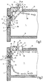
- FIG. 1 shows, in cross-section, a section of a room 1 to be conditioned of a building or the like.
- the room has a facade wall 2 with a window opening 3.
- a window 4 which has a fixed frame 5 and a movable sash 6.
- the window sash 6 can be pivoted about a lower, horizontal tilting axis 7 in order to set a corresponding outside air opening cross-section 8.
- the room 1 also has a bottom 9 and a ceiling 10.
- an air conditioner 11 is inserted in alignment.
- the air conditioner 11 is located immediately adjacent to the facade wall 2 and is designed as a fan coil 12. Due to its arrangement in the ceiling 10, the fan coil 12 forms a ceiling unit 13.
- the fan coil 12 has in the area near the window 4 an air inlet opening 14 and further away from the window 4- an air outlet opening 15. Between the air inlet opening 14 and the air outlet opening 15 is -in the interior of the fan coil 12- a fan 16 and downstream of the fan 16- a heat exchanger 17 is arranged. The speed of the fan 16 is adjustable, so that with him a corresponding air flow rate 18 is promoted. This air volume flow 18 enters through the air inlet opening 14 in the fan coil 12 and through the air outlet opening 15 back into the room 1.
- the heat exchanger 17 are associated with supply and discharge lines 19 for a centrally treated heating or cooling means, wherein the volume flow of the heating or cooling means by means of a Volumenstromeinstell 180 is adjustable.
- a drive device 21 for the actuation of the window sash 6 is attached on the window sash 6 of the window 4.
- the drive device 21 is connected via a force-effective path 22 with the frame 5.
- the drive device 21 acts on the force-effective section 22 and thereby spends the window sash 6 in the respective desired open position, so that adjusts a corresponding outside air opening cross-section 8.
- the drive means 21 has a locking device 23 which cooperates with a drive rod system of the window 4, not shown. In this way it is ensured that upon actuation of the drive device 21, first by means of the locking device 23, an unlocking of the window sash 6 takes place before it is spent in the open position. If the window sash 6 is closed, then the locking device 23 of the drive device 21 ensures that a lock is performed after closing the window sash 6.
- control or regulating device 25 In the housing 24 of the drive device 21 is also a control or regulating device 25, the -in dependence of certain parameters, the air conditioning of the room 1 controls or regulates. This will be discussed in more detail below.
- the control or regulating device can also be accommodated at a different location of the room 1.
- FIG. 1 works as follows: As can be seen, the window sash 6 has a certain open position, which allows the entry of outside air 26. Because in the FIG. 1 the summer case is shown, penetrates relatively warm outside air 26 in the upper region of the window 4 in the room 1 and passes to the air inlet opening 14 of the fan coil 12, promoted by the fan 16. This air passes through the heat exchanger 17 and is a cooling vortex- by a corresponding coolant 27, which flows through the heat exchanger 17, cooled. The cooled air passes through the air outlet opening 15 in the room 1 back. This conditioned air 28 substantially flows obliquely downwardly from the window 4 and enters a residence zone of the room 1.
- a portion of the conditioned air 28 may also flow in the direction of the façade wall 2, depending on the construction.
- the control device 25 controls or regulates the aforementioned air conditioning process by controlling the drive device 21 in accordance with the air conditioning requirements desired in the room 1, so that the outside air opening cross-section 8 which makes sense for the present ventilation task is established.
- control or regulating device 25 ensures, by corresponding activation of the volume flow setting device 20, that a corresponding volume flow of the coolant 27 flows through the heat exchanger 17. All said control or regulatory tasks are coordinated, so that a combined control or regulation is present, which leads to optimal climate conditions of the room 1.
- the control or regulation device 25 senses the present actual parameters and uses a corresponding program control, stored value tables and / or value curves and so on - a corresponding control or regulation.
- even the humidity in the room 1 can be set if the fan coil 12 has a corresponding moistening / dehumidifying device.
- FIG. 2 corresponds to the embodiment of FIG. 1 , but clarifies the winter case when relatively low outside air temperatures are present.
- the outside air temperature is lower than the temperature of the room air. This has the result that penetrates through the outside air opening cross section 8 penetrating outside air 26 in the lower side regions of the window 4 in the room 1, sinks down and flows in the area above the bottom 9 to the not shown residence zone of the room 1.
- Warm indoor air 29, which is is located in the ceiling-near zone of the room 1 flows through the upper zone of the outside air-opening cross-section 8 from the inside to the outside.
- a portion 30 of the room air 29 is sucked in-Um Kunststoffmaschine- of the air inlet opening 14 of the fan coil 12, heated by means of the heat exchanger 17 and passes through the air outlet opening 15 in the room 1 back. This returned, heated air flows away from the facade wall 2 in the area of the ceiling of the room 1 to the occupied zone.
- the control or regulating device 25 provides in combination control or regulation for the adjustment of the outside air opening cross-section 8, the speed of the fan 16 to adjust the air flow rate of working as an air conditioner 11 fan coil 12 and also actuates the flow adjustment device 20 for adjustment the volume flow of a heating medium 31, which is processed centrally and flows through the heat exchanger 17.
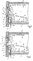
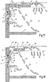
- FIG. 3 shows an embodiment of an arrangement for the air conditioning of a room 1, which differs from the embodiment of the FIG. 1 differs in that instead of a ceiling device 13, a sill device 32 is used, which is disposed below the window 4 adjacent to the facade wall 2 and formed as a fan coil 12. It has at its upper end face 33 an air inlet opening 14 and in the lower zone of its front side 34, an air outlet opening 15, which is associated with a heat exchanger 17. Above the heat exchanger 17 is located inside the sill device 32, a fan 16th
- FIG. 3 In the embodiment of FIG. 3 is the summer case. This means that relatively warm outside air 26 flows through the upper region of the outside air opening cross-section 8 of the window 4 into the room 1, where it reaches the occupied zone in the area of the ceiling 10. Cooler room air 29 flows in the middle zone of the room 1 in the direction of the facade wall 2 and thereby enters partially through the lateral areas of the outside air opening cross-section 8 to the outside and partially into the air inlet opening 14 of the fan coil 12 a. This proportion of room air is conveyed by the fan 16 and passes through the heat exchanger 17, which assumes a cooling function.
- a centrally treated coolant 27 is metered by the common control or regulating unit 25, which also controls or regulates the other parameters in common, that already combined to the embodiments of the Figures 1 and 2 were called.
- the cooled, the parapet 32 leaving air flows as a source ventilation to form a cold air lake according to the arrows 35 in the region of the bottom zone of the room 1 in the occupied zone.
- the embodiment of FIG. 4 differs from the embodiment of FIG. 3 only in that the window sash 6 does not have a horizontal tilting axis 7 in its lower region, but has a horizontal tilting axis 7 approximately in its middle zone, ie, in the exemplary embodiment of FIG. 4 Not only in the side zones of the window sash 6, but also in the upper and in the lower zone of the sash 6 in its open position, an outside air opening cross-section 8 created.
- the embodiment of FIG. 4 is also the summer case.
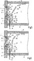
- FIG. 5 shows an embodiment of an arrangement for the air conditioning of a room 1 that the embodiment of the FIG. 3 equivalent.
- the FIG. 6 shows an embodiment of the embodiment of the FIG. 4 equivalent. Different from the figures of the embodiments of FIGS. 3 and 4 is in the embodiments of FIGS. 5 and 6 only that in the two latter embodiments of the winter case exists. In the embodiments of the FIGS. 5 and 6 it is also a source ventilation. It can be seen that cool outside air 26 partially flows into the air inlet opening 14 of the sill device 32 and partially enters the room 1. The inflow of the outside air 26 takes place in the lower side region of the window 4 (exemplary embodiment of FIGS FIG. 5 ) And additionally in the lower longitudinal zone of the window 4 in the embodiment of FIG.
- each of a fan coil 12th be formed.
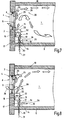
- the arrangement of FIGS. 7 and 8 corresponds essentially to the arrangement of FIG. 5
- the sill device 32 sucks in the embodiments of FIGS. 7 and 8 Room air in the lower zone of its front 34, so that there is the air inlet opening 14 and the upwardly facing, lying below the window 4 end face 33 of the sill device 32 has the air outlet opening 15, so far as the embodiment of the FIG. 5 with respect to the air inlet opening 14 and the air outlet opening 15 according to inverse conditions.
- FIG. 7 concerns the summer fall; the FIG. 8 the winter fall.
- a combined control is performed by a controller 25 that controls or regulates at least the following: outside air opening area 8, air volume flow 18 from the sill 32 and volumetric flow of a heating or cooling means 31, 27 of the heat exchanger 17 of the sill device 32.
- FIG. 8 is the winter case, ie, cold outside air 26 flows in the lower regions of the side zone of the window 4 in the room 1, and thereby meets coming from the sill device 32 warm air.
- This warm air results from in the bottom zone of the room 1 sucked in room air 29, which is heated in the heat exchanger 17 and blown obliquely upward along the window 4 in the room 1.
- This blown air impinges on the cool outside air 26, so that there is formed a mixing zone 39 in front of the window 4 within the space 1.
- the mixed air thus formed rises into the area of the ceiling zone of the room 1 and from there into the occupied zone.
- Room air 29 flows in the upper region of the outside air opening cross-section 8 through the open window 4 to the outside.
- FIGS. 9 and 10 correspond to the embodiment of FIG. 3
- a bottom device 40 is provided instead of the sill device 32.
- This floor unit 40 is recessed in the bottom 9 of the room 1 and is located below the window 4, adjacent to the facade wall 2.
- the floor unit 40 is formed as a fan coil 12 and has a fan 16 and a heat exchanger 17.
- the heat exchanger 17 is in Summerfall the FIG. 9 with a coolant 27 and winter in the FIG. 10 with a heating means 31 each metered by a volume flow adjuster 20, supplied.
- the control or regulating device 25 applies the corresponding, which has already been said to the other embodiments.
- the floor unit 40 is oriented such that an air inlet opening 14 is farther away from the facade wall 2 and an air outlet opening 15 is located relatively close to the facade wall 2 in the region of the bottom 9.
- FIG. 9 enters through the outside air opening cross-section 8 warm outside air 26 in the room 1 and sweeps along the ceiling zone to get to the occupied zone.
- the floor unit 40 draws in via the air inlet opening 14 room air 29 as air volume flow 18, which is cooled in the heat exchanger 17 and blown out of the air outlet opening 15 upwards in the area of the facade wall 2 in the room 1.
- the air rises and thereby meets with outflowing room air 29, which leaves the room 1 from the side areas of the opened window 4.
- the mixed air thus formed lowers again at the level of the window 4 inside the room and then flows away from the window in the direction of the occupied zone of the room.
- the winter case is in the design as a floor fan convector with mixed source ventilation. Since there is relatively cold outside air 26, this flows into the lower part of the window 4 in the room 1. Warmer room air 29 flows in the upper area of the window 4 from the room 1 outside. The air inlet opening 14 of the floor unit 40 sucks in room air 29 as air volume flow 18 and heats it in the heat exchanger 17. The heated air exits from the air outlet opening 15 in the region of the bottom 9 near the facade wall 2 upwards and meets there in the window sill and in an overlying zone on the outside air 26 flowing through the side areas of the window 4, so that air mixing takes place here. This mixed air then rises obliquely upward with increasing distance to the facade wall 2 to in the ceiling area of the room 1 and finally comes out of the FIG. 10 not visible living zone of room 1.
- the combinatorial control or regulating device 25 which has already been mentioned several times, also acts here.
- FIG. 11 again illustrates the execution of the fan convector 12 as a base unit 40 with heat exchanger 17 and fan 16.
- the installation is made in alignment with the bottom 9 of the room 1, ie, the top 41 of the bottom 9 is aligned with the top 42 of the floor unit 40th Das Boden réelle 40 adjoins the facade wall 2 of the room 1.
- FIG. 12 illustrates once again the execution of the fan coil 12 as parapet device 32 with fan 16 and heat exchanger 17.
- the heat exchanger 17 extends over the entire front side 34 of the fan coil 12; the fan 16 is located next to the heat exchanger 17 in the region of the lower half.
- FIG. 13 shows an embodiment that the the FIG. 12 equivalent. Therefore, there is also a sill device 32, but in contrast to the embodiment of FIG. 12 -
- the heat exchanger 17 is disposed below the fan 16 arranged above it.
- FIG. 14 illustrates the execution of an air conditioner 11 not in the form of a fan convector, but in the form of an induction device.
- all embodiments described above, which include a fan coil 12, instead of this fan coil 12, could also have an induction unit 43. It is also possible; to accommodate in a room 1 a plurality of air conditioners 11, which may be either all fan coil units or all induction units or mixed, fan coil (s) and induction unit (s).
- the induction device has an air distribution box 44, which is supplied with centrally processed air and / or with room air and / or outside air by means of a corresponding device, such as a fan or by connection to a pressure air line.
- the air of the Heilverteilkastens 44 enters from induction nozzles 45 in a mixing chamber 46 a.
- a mixing chamber 46 a In the FIG. 14
- only one induction nozzle 45 is shown.
- FIGS. 11 to 14 resulting devices in different mounting positions in the To arrange space 1 so that they form either a ceiling device 13, a sill device 32 or a floor unit 40.
- FIGS. 15 and 16 illustrate the drive means 21 for the actuation of the window sash 6.
- the drive means 21 has a housing 24 in which an electric motor with gear is arranged.
- the control or regulating device 25 is also arranged in the housing 24.
- the arrangement is such that the housing 24 is mounted on the window sash 6 and that the base body 49 is attached to the frame 5 of the window 4.
- the control or regulating device 25 gives corresponding signals to the drive of the drive device 21, so that the eccentric 47 is actuated and a force is transmitted via the articulated rod 48 to the base body 49, which causes it to open or close or to adjust the Outside air opening cross section 8 comes.
- the arrangement is preferably made such that a square protrudes from the underside of the housing 24, which cooperates with the drive rod system (not shown) of the window 4 and can perform a locking or unlocking of the window 4. In operation, therefore, the window is first unlocked and then moved to a corresponding open position. Accordingly, when the window is closed, the window sash 6 is first moved into the closed position and then the locking is effected by means of the drive rod system.
- the invention may include further sensors which detect, for example, certain areas of the room in terms of temperature. Furthermore, it is possible to additionally or alternatively sense the wind pressure or the wind speed and to take it into account in the control or regulation.
- tilting windows are used as windows.
- the invention can also be applied to rotary windows if the window drive is designed accordingly.
- the axis of rotation is preferably in one of the two side regions of the window sash.
- the mentioned source vents ensure a high temperature stratification in the summer, since low air velocities are present.
- the cooled air stays on the floor and does not flow over the window. It results in a low energy loss.
- the source ventilation has the advantage that in the heating mode, a cold air drop is prevented on the window pane. Heat loss from hot air escaping through the window can be considered low.
- the mentioned mixed-source ventilation leads in summer to a lower temperature stratification compared to a pure displacement ventilation, as a room air admixing takes place. A risk of short circuit can be prevented by appropriate steering of the air.
- the mixed-displacement ventilation in the heating mode prevents a cold air drop at the window pane. Shielding by fans, which is more effective than in the case of forced ventilation, can preferably take place. The heat loss through escaping through the window warm air can be kept very low, so they do not interfere appear.
- the advantage that warm ceiling air is sucked in which has a higher cooling performance. It sets a very low temperature stratification.
- control or regulating method according to the invention in particular as another, to be taken into account by the combined control Parameters that take into account the outside temperature. Furthermore, it is additionally or alternatively possible to sense the internal temperature, in particular in the floor area, in order to avoid low floor temperatures.
- the aim of the window ventilation is to cover the fresh air requirement of the room.
- inexpensive fresh air is used due to the window ventilation, which is aftertreated to improve the indoor climate.
- the fresh air requirement depends on the number of people in the room and can be pretended accordingly.
- the control and / or regulation then sets the appropriate outside air opening area.
- the pressure conditions on the facade of the outside air opening having space and / or the pressure conditions at the outside air opening are taken into account. If there is a high facade pressure, a small opening is set. The fresh air requirement remains constant. At low facade pressure, a large outside air opening is set, while also the fresh air requirement is kept constant.
- the outside air opening is closed and optionally another outside air opening, in particular another window, is automatically opened, in which there is overpressure.
- this procedure can only be carried out if the conditions mentioned are present.
- the controller or controller may include a map in which a desired value is set. By measuring the temperature and / or pressure and / or velocity of the air at the window and the room temperature, an actual value is determined. Now window drive, valves or the heat exchanger and speed of the fan or fans are controlled in order to come to the required target value.
- the fan speed of the air conditioner or the air conditioning units preferably also according to the ventilation method, which can / can be operated in source ventilation or mixed-source ventilation. Furthermore, there is a dependency on the placement of the air conditioner or devices, in particular whether this or these are arranged on the ceiling, the balustrade and / or the floor. In this case, it is possible for the air conditioning unit (s) to realize a source ventilation and / or mixed source ventilation.
- breather in which the outside air opening, in particular the window or the like is opened periodically. Also a change of operation - window on, air conditioning off or window closed, air conditioning on - is conceivable.
- FIGS. 17 and 18 show two further embodiments of an inventive arrangement in which a so-called "silent cooling" is realized.
- the summer case ie, the room 1 should be cooled.
- FIG. 17 is in the ceiling 10 of the room 1 as an air conditioner 11, only a heat exchanger 17 is provided air drive means, in particular a fan, are not available.
- the heat exchanger 17 is installed flush with the ceiling 10 and has a Jardinzziströmkanal 51 on its side facing away from the room.
- the ceiling 10 starts from the facade wall 2 of the room 1 and ends at a distance from the facade wall 2. This allows room air 29 rise above the ceiling level 52 and enter the Jardin povertyzuströmkanal 51 and flow to the heat exchanger 17.
- the room air 29 is cooled and then enters from top to bottom - coming from the ceiling area - in the room 1 again.
- Outside air 26 enters through the outside air opening cross-section 8 in the upper region of the window 4 in the room 1 and meets the coming of the heat exchanger 17 cooled room air 29. It results in a mixing and the mixed air decreases according to the oblique arrows 53 in the Living zone of the room 1. Room air 29 can leave the room 1 via the side areas of the opened window 4.
- FIG. 18 is different from that of FIG. 17 in that the ceiling 10 leaves the facade wall 2 a free space 55, which forms an air inflow channel 56.
- the ceiling 10 leaves the facade wall 2 a free space 55, which forms an air inflow channel 56.
- the air conditioner 11 only the heat exchanger 17 and no air drive means.
- warm room air 29 rises due to their low specific weight and is due to the cooling heat exchanger 17 led.
- the now cooler air with its higher specific gravity then sinks back into the room 1.
- outside air enters the room 1.
- the conditions for combined control and / or regulation already presented for the above exemplary embodiments otherwise apply correspondingly. At least by means of this control and / or regulation of the outside air opening cross-section and the volume flow of a heating and / or cooling medium, in particular a coolant, controlled or regulated by the heat exchanger 17 of the air conditioner 11.
Description
Die Erfindung betrifft ein Verfahren zur Klimatisierung eines Raumes, bei dem Außenluft durch eine nicht mit einem Klimagerät verbundene Außenluftöffnung in den Raum strömen kann und Raumluft mittels des mindestens einen Klimageräts konditionierbar ist.The invention relates to a method for air conditioning a room in which outside air can flow through a not connected to an air conditioner outside air opening into the room and room air is conditioned by means of at least one air conditioner.
Ein Verfahren der vorstehend genannten Art wird dann durchgeführt, wenn ein Raum eines Gebäudes oder dergleichen mittels eines Klimageräts klimatisiert wird und gleichzeitig ein Fenster des Raumes offen steht. Das offen stehende Fenster kann -je nach Außenluft-temperatur- dazu führen, dass -insbesondere im Sommer- die Raumlufttemperatur ansteigt. Befindet sich im Raum ein Temperatursensor des Klimageräts, so wird die Temperaturerhöhung registriert und vom Klimagerät der Versuch unternommen, die Raumlufttemperatur wieder zu senken. Entsprechend umgekehrte Verhältnisse sind insbesondere im Winter zu erwarten, d.h., das offen stehende Fenster führt zu einer starken Raumluftabkühlung, die das Klimagerät zu kompensieren versucht. Insgesamt ist festzustellen, dass aufgrund des offen stehenden Fensters kein ordnungsgemäßer Klimatisierungsbetrieb möglich ist.A method of the type mentioned above is carried out when a room of a building or the like is conditioned by means of an air conditioner and at the same time a window of the room is open. Depending on the outside air temperature, the open window may cause the room air temperature to rise, especially in summer. If a temperature sensor of the air conditioner is located in the room, the temperature increase is registered and the air conditioner attempts to lower the room air temperature again. Correspondingly reverse conditions are to be expected especially in winter, that is, the open window leads to a strong room air cooling, which tries to compensate for the air conditioner. Overall, it should be noted that due to the open window no proper air conditioning operation is possible.
Der Erfindung liegt die Aufgabe zugrunde, ein Verfahren zur Klimatisierung eines Raumes anzugeben, dass einen hinreichenden Frischluftanteil in einem Raum bei gleichzeitiger optimalen Klimatisierung des Raumes gewährteistet.The invention has for its object to provide a method for air conditioning of a room that gewährteistette a sufficient proportion of fresh air in a room while optimizing the air conditioning of the room.
Diese Aufgabe wird gelöst durch ein Verfahren laut Anspruch 1, insbesondere durch die kombinierte Steuerung oder Regelung mindestens folgender Größen: Außenluft-Öffnungs-querschnitt, und Volumenstrom eines Heiz- und/oder Kühlmittels durch mindestens einen Wärmetauscher des Klimageräts. Die vorstehend genannten Größen werden durch die kombinierte, also unter sich abgestimmte und die jeweils vorliegende Situation berücksichtigende Steuerung oder Regelung fortlaufend oder in kurzen Zeitabständen so eingestellt, dass sich optimale Klimatisierungsverhältnisse im Raum ergeben. Ein entsprechend groß eingestellter Außenluft-Öffnungsquerschnitt stellt den Zustrom von frischer Luft sicher. Hierbei wird vorzugsweise auch die Außenlufttemperatur berücksichtigt, um im Raum die gewünschte Raumlufttemperatur zu erhalten oder beizubehalten. Die Steuerung oder Regelung des Luft-Volumenstromes des Klimagerätes führt zu einer entsprechend großen Volumenstrombehandlung der Raumluft, die im Umluftverfahren konditioniert wird. Da das Klimagerät einen Wärmetauscher aufweist, der durch einen entsprechend eingestellten Volumenstrom eines Heiz- oder Kühlmittels den Luft-Volumenstrom der Raumluft im gewünschten Maße erwärmen oder abkühlen kann, wird die gewünschte Raumtemperatur eingestellt. Im Falle einer so genannten "Stillen Kühlung" erfolgt die kombinierte Steuerung oder Regelung des Außenluft-Öffnungsquerschnitts und des Volumenstroms eines Heiz- und/oder Kühlmittels, insbesondere Kühlmittels, durch mindestens einen Wärmetauscher des Klimageräts. Die kombinierte Steuerung oder Regelung stellt stets sicher, dass beispielsweise im Falle sehr niedriger Außentemperaturen der Außenluft-Öffnungsquerschnitt möglichst klein gehalten wird, um ein unangenehmes Raumklima zu vermeiden. Dennoch wird durch die Außenluftzufuhr ein hinreichender Sauerstoffgehalt der Raumluft garantiert. Insbesondere kann auch vorgesehen sein, dass im vorstehend erwähnten Falle der Querschnitt der Außenluft-Öffnung nicht permanent offen gehalten, sondern nur stoßweise zum Zwecke einer sogenannten Stoßlüftung aufgefahren und anschließend die Außenluft-Öffnung, insbesondere ein Fenster oder dergleichen, wieder verschlossen wird.This object is achieved by a method according to
Ferner ist von Vorteil, wenn als Klimagerät ein Ventilatorkonvektor verwendet wird. Der Ventilatorkonvektor weist als wesentliche Komponenten einen Ventilator zur Luftförderung und den bereits erwähnten Wärmetauscher auf, dessen Heiz- oder Kühlmittel im Volumenstrom verändert werden kann. Wird eine Drehzahlbeeinflussung des Ventilators vorgenommen, so kann hierdurch der vorstehend erwähnte Luft-Volumenstrom eingestellt werden.It is also advantageous if a fan coil is used as air conditioner. The fan coil unit has as essential components a fan for conveying air and the already mentioned heat exchanger whose heating or cooling medium can be varied in the volume flow. If a speed influence of the fan is made, then the above-mentioned air volume flow can be adjusted thereby.
Zusätzlich oder alternativ ist es auch möglich, wenn als Klimagerät ein Induktionsgerät verwendet wird. Die Induktionswirkung wird dadurch erzielt, dass mittels einer Luftfördereinrichtung, beispielsweise eines Ventilators, Raumluft angesaugt und Luftdüsen zugeführt werden. Die Luftdüsen erzeugen in einem Mischraum einen Unterdruck, durch den weitere Raumluft angesaugt wird, die den erwähnten Wärmetauscher passiert. Der Volumenstrom eines Heiz- oder Kühlmittels des Wärmetauschers lässt sich entsprechend mittels der kombinierten Steuerung oder Regelung beeinflussen.Additionally or alternatively, it is also possible if an induction device is used as an air conditioner. The induction effect is achieved by sucking in air and air nozzles by means of an air conveyor, such as a fan. The air nozzles generate in a mixing chamber a negative pressure, is sucked through the more room air that passes through the mentioned heat exchanger. The volume flow of a heating or cooling medium of the heat exchanger can be influenced accordingly by means of the combined control or regulation.
Nach einer Weiterbildung ist es möglich, dass nicht nur durch den Außenluft-Öffnungsquerschnitt Außenluft in den Raum gelangen kann, sondern dass das Klimagerät, insbesondere der Ventilatorkonvektor und/oder das Induktionsgerät auch Außenluft in den Raum einbringt. Im Falle des Ventilatorkonvektors kann dessen Ventilator beispielsweise Raumluft, Außenluft oder sowohl Raumluft und Außenluft fördern und dabei den geförderten Luftstrom mittels des Wärmetauschers konditionieren. Im Falle des Induktionsgerätes ist es möglich, den Luftdüsen Raumluft oder Außenluft oder sowohl Raumluft und Außenluft zuzuführen.According to a development, it is possible that outside air can enter the room not only through the outside air opening cross section, but that the air conditioner, in particular the fan coil and / or the induction device also introduces outside air into the room. In the case of the fan coil, the fan may, for example, convey room air, outside air or both room air and outside air and thereby condition the conveyed air flow by means of the heat exchanger. In the case of the induction device is it is possible to supply the air nozzles with room air or outside air, or with both room air and outside air.
Außenluft kann dem Raum über den bereits erwähnten Außenluft-Öffnungsquerschnitt also durch die Außenluftöffnung und/oder einen zusätzlichen Außenluftzugang zugeführt werden. Durch die Außenluftöffnung gelangt die Außenluft stets direkt in den Raum, ohne dass diese das Klimagerät passiert. Zusätzlich oder alternativ ist es möglich, durch einen Außenluftzugang dem Klimagerät, das als Ventilatorkonvektor und/oder als Induktionsgerät ausgebildet sein kann, Außenluft zuzuführen. Zusätzlich oder alternativ besteht überdies die Möglichkeit, dass ein bestimmter Anteil der durch die Außenluftöffnung in den Raum strömende Luft vom Klimagerät angesaugt und konditioniert wird. Ein anderer Anteil der Außenluft verteilt sich ohne das Passieren des Klimagerätes im Raum.Outside air can be supplied to the room via the already mentioned outside air opening cross-section through the outside air opening and / or an additional outside air access. Through the outside air opening the outside air always gets directly into the room, without them passing the air conditioner. Additionally or alternatively, it is possible, by an outside air access to the air conditioner, which may be configured as a fan coil and / or induction device to supply outside air. Additionally or alternatively, there is also the possibility that a certain proportion of the air flowing through the outside air opening into the room is sucked in and conditioned by the air conditioning unit. Another part of the outside air is distributed without passing through the air conditioner in the room.
Nach einer Weiterbildung der Erfindung ist vorgesehen, dass das Klimagerät, der Ventilatorkonvektor und/oder das Induktionsgerät mit zentral aufbereiteter Primärluft versorgt wird. Bei der zentral aufbereiteten Primärluft handelt es sich vorzugsweise um Außenluft, die im Hinblick auf ihre Parameter, insbesondere Temperatur und/oder Luftfeuchtigkeit, zentral aufbereitet und dann über entsprechende Luftkanäle dem Klimagerät, dem Ventilatorkonvektor und/oder dem Induktionsgerät zugeführt wird. Zusätzlich oder alternativ ist es auch möglich, dass zumindest ein Anteil der zentral aufbereiteten Primärluft ohne das Passieren des Klimageräts in den zu klimatisierenden Raum gelangt. In einem solchen Falle wird die kombinierte Steuerung/Regelung den Volumenstrom dieser zentral aufbereiteten primären Luft mit kontrollieren.According to a development of the invention it is provided that the air conditioner, the fan coil and / or the induction unit is supplied with centrally processed primary air. The centrally processed primary air is preferably outside air, which is processed centrally with regard to its parameters, in particular temperature and / or air humidity, and then supplied via appropriate air ducts to the air conditioning unit, the fan coil unit and / or the induction unit. Additionally or alternatively, it is also possible that at least a portion of the centrally processed primary air passes without passing through the air conditioner in the room to be air-conditioned. In such a case, the combined control will control the flow rate of this centrally treated primary air.
Insbesondere kann vorgesehen sein, dass der Raum im Wesentlichen mittels Quelllüftung klimatisiert wird.In particular, it can be provided that the space is essentially conditioned by means of displacement ventilation.
Nach einer Weiterbildung der Erfindung ist vorgesehen, dass der Raum im Wesentlichen mittels Mischquelllüftung klimatisiert wird.According to a development of the invention, it is provided that the space is air conditioned essentially by means of mixed source ventilation.
Die Erfindung betrifft ferner eine Anordnung zur Klimatisierung eines Raumes, bei der Außenluft durch eine nicht mit einem Klimagerät verbundene Außenluftöffnung in den Raum strömen kann und Raumluft mittels des mindestens einen Klimageräts konditionierbar ist, wobei eine Steuer- und/oder Regeleinrichtung für die kombinierte Steuerung und/oder Regelung mindestens folgender Größen vorgesehen ist: Außenluft-Öffnungsquerschnitt und Volumenstrom eines Heiz- und/oder Kühlmittels durch mindestens einen Wärmetauscher des Klimageräts.The invention further relates to an arrangement for the air conditioning of a room in which outside air can flow through a not connected to an air conditioner outside air opening into the room and room air is conditioned by means of at least one air conditioner, wherein a control and / or regulating device for the combined control and / or regulation of at least the following sizes is provided: outside air opening cross-section and volume flow of a heating and / or coolant through at least one heat exchanger of the air conditioner.
Bei dem Klimagerät kann es sich insbesondere um einen Ventilatorkonvektor und/oder ein Induktionsgerät handeln. Der Ventilatorkonvektor und/oder das Induktionsgerät können zentrale oder dezentrale Geräte sein. Handelt es sich um zentrale Geräte, so sind sie in dem zu klimatisierenden Raum zugeordnet, werden jedoch von zentral aufbereiteter Luft versorgt. Die zentralen Geräte im Raum dienen der Nachbehandlung der aufbereiteten Luft - insbesondere Heizen oder Kühlen - oder sie mischen Raumluft bei, bevor die Nachbehandlung erfolgt. Bei dezentralen Geräten handelt es sich um im Raum aufgestellte Geräte. Diese Geräte sind insbesondere auf das Luftvolumen und die sonstigen Anforderungen (Temperatur und/oder Luftfeuchtigkeit) des zu klimatisierenden Raumes ausgelegt.The air conditioner may in particular be a fan coil and / or an induction unit. The fan coil and / or the induction unit may be central or remote units. If they are central units, they are allocated in the room to be air-conditioned, but are supplied with centrally treated air. The central devices in the room are used for the aftertreatment of the treated air - in particular heating or cooling - or they mix in room air before the aftertreatment takes place. Decentralized devices are devices installed in the room. These devices are designed in particular for the volume of air and other requirements (temperature and / or humidity) of the room to be air conditioned.
Die Außenluftöffnung wird von dem Querschnitt eines dem Raum zugeordneten Fensters, einer Tür oder dergleichen gebildet. Mittels der kombinierten Steuerung oder Regelung wird der Außenluft-Öffnungsquerschnitt entsprechend eingestellt. Handelt es sich bei der Außenluftöffnung beispielsweise um den Öffnungsquerschnitt eines Fensters, so lässt sich die Fensterflügelstellung mittels einer geeigneten Antriebseinrichtung vorzugsweise stufenlos oder in Stufen verändern, um den erforderlichen Öffnungsquerschnitt zum Einströmen von Außenluft bereitzustellen. Die Antriebseinrichtung wird von der kombinierten Steuerung oder Regelung kontrolliert, so dass eine steuer- oder regelbare Antriebseinrichtung vorliegt. Insbesondere kann die Antriebseinrichtung einen Elektromotor zur Einstellung des Außenluft-Öffnungsquerschnitts aufweisen. Da aus Sicherheitsgründen die Außenluftöffnung zu verriegeln ist, wenn sich zum Beispiel keine Personen in dem Raum aufhalten oder nachts das Gebäude nicht zugänglich sein soll, kann die erwähnte Antriebseinrichtung oder eine separate Einrichtung eine Verriegelungseinrichtung des Fensters, der Tür oder dergleichen zum Entriegeln oder Verriegeln des Fensterflügels, des Türflügels oder dergleichen betätigen. Für eine Öffnung zum Einströmen von Außenluft ist es daher dann erforderlich, zunächst eine Entriegelung vorzunehmen und dann - beispielsweise im Falle eines Fensters- den Fensterflügel entsprechend weit zu öffnen. Bei einer Verriegelung ist zunächst vorgesehen, dass der Außenluft-Öffnungsquerschnitt geschlossen und dann das Fenster, die Tür oder dergleichen verriegelt wird. Dieses Entriegeln oder Verriegeln kann im Falle eines Fensters beispielsweise mittels eines Treibstangensystems erfolgen, dass von der Antriebseinrichtung oder der separaten Einrichtung angetrieben wird. Manuelle Eingriffe sind daher nicht erforderlich.The outside air opening is formed by the cross section of a window associated with the room, a door or the like. through the combined control or regulation of the outside air opening cross section is adjusted accordingly. If the outside air opening is, for example, the opening cross section of a window, then the window sash position can preferably be varied steplessly or in steps by means of a suitable drive device, in order to provide the required opening cross section for the inflow of outside air. The drive device is controlled by the combined control or regulation, so that a controllable or controllable drive device is present. In particular, the drive device may have an electric motor for adjusting the outside air opening cross section. Since, for safety reasons, the outside air opening is to be locked, for example if there are no persons in the room or at night the building should not be accessible, the mentioned drive device or a separate device may include a locking device of the window, the door or the like for unlocking or locking the Press sash, the door leaf or the like. For an opening for the influx of outside air, it is therefore necessary to first perform an unlocking and then - for example, in the case of a window - to open the window sash accordingly. With a lock, it is initially provided that the outside air opening cross section is closed and then the window, the door or the like is locked. This unlocking or locking can be done in the case of a window, for example by means of a drive rod system that is driven by the drive device or the separate device. Manual intervention is therefore not required.
Insbesondere kann die Steuer- oder Regeleinrichtung der Antriebseinrichtung zugeordnet sein. Hierzu kann die Steuer- oder Regeleinrichtung und die Antriebseinrichtung in einem gemeinsamen Gehäuse untergebracht werden. Diese Kombination aus Steuer- oder Regeleinrichtung und der Antriebseinrichtung befindet sich insbesondere am Fenster, der Tür oder dergleichen, vorzugsweise am Fensterflügel, am Türflügel oder dergleichen. Im Fensterantriebsgehäuse können nicht nur Antrieb und Steuerung beziehungsweise Regelung untergebracht sein, sondern auch Sensoren. Diese Sensoren sind insbesondere Lufttemperaturfühler und/oder Luftgeschwindigkeitsmesser. Nach den genannten Parametern Lufttemperatur und Luftgeschwindigkeit richtet sich der Außenluft-Öffnungsquerschnitt, die Ansteuerung des Ventilators und damit der Luft-Volumenstrom des Klimageräts, sowie der Öffnungsquerschnitt der Ventile, also der Volumenstrom des Heiz- und/oder Kühlmittels durch den mindestens einen Wärmetauscher des Klimageräts. Befindet sich die erwähnte Kombination beispielsweise am Fensterflügel, so ist dadurch sichergestellt, dass das Treibstangensystem des Fensterflügels zum Ver- oder Entriegeln betätigt werden kann.In particular, the control or regulating device may be assigned to the drive device. For this purpose, the control or regulating device and the drive means are housed in a common housing. This combination of control or regulating device and the drive device is located in particular on the window, the door or the like, preferably on the window sash, on the door leaf or the like. In the window drive housing not only drive and control or regulation can be accommodated, but also sensors. These sensors are in particular air temperature sensors and / or air speed meters. After the above parameters air temperature and air speed, the outside air opening cross section, the control of the fan and thus the air volume flow of the air conditioner, as well as the opening cross section of the valves, so the volume flow of the heating and / or cooling means by the at least one heat exchanger of the air conditioner , The mentioned combination is, for example, on the window sash, this ensures that the drive rod system of the sash can be operated for locking or unlocking.
Der Ventilatorkonvektor kann insbesondere als Boden-, Brüstungs- und/oder Deckengerät ausgebildet sein.The fan coil can be designed in particular as floor, parapet and / or ceiling unit.
Schließlich ist vorgesehen, dass das Induktionsgerät ein Boden-, Brüstungs- und/oder Deckengerät ist.Finally, it is provided that the induction device is a floor, parapet and / or ceiling device.
Die Zeichnungen veranschaulichen die Erfindung anhand von Ausführungsbeispielen und zwar zeigt:
Figur 1- eine schematische Schnittansicht durch den Fassadenbereich eines zu klimatisierenden Raumes mit einem Fenster und einem Decken-Ventilatorkonvektor,
Figur 2- eine der
Figur 1 entsprechende Anordnung, Figur 3- eine der
Figur 1 entsprechende Anordnung, jedoch mit einem Brüstungs-Ventilatorkonvektor, Figur 4- eine der
Figur 3 entsprechende Anordnung, Figur 5- eine der
Figur 3 entsprechende Anordnung, Figur 6- eine der
Figur 3 entsprechende Anordnung, Figur 7- eine der
Figur 3 entsprechende Anordnung, Figur 8- eine der
Figur 3 entsprechende Anordnung, Figur 9- eine der
Figur 1 entsprechende Anordnung, jedoch mit Boden-Induktionsgerät, Figur 10- eine der
Figur 9 entsprechende Anordnung, Figur 11- einen Abschnitt eines Raumes in Schnittansicht mit im Bereich der Fassade angeordnetem Boden-Ventilatorkonvektor,
Figur 12- eine der
Figur 11 entsprechende Anordnung, jedoch mit Brüstungs-Ventilatorkonvektor, Figur 13- eine der
Figur 12 entsprechende Anordnung, jedoch mit andersartig konstruiertem Brüstungs-Ventilatorkonvektor, Figur 14- eine der
Figur 1 entsprechende Anordnung, jedoch mit Brüstungs-Induktionsgerät, Figur 15- eine Antriebsvorrichtung zum motorischen Öffnen sowie Schließen und Verriegeln sowie Entriegeln eines Fensters, einer Tür oder dergleichen,
Figur 16- eine Seitenansicht der Antriebsvorrichtung gemäß
Figur 15 , Figur 17- ein weiteres Ausführungsbeispiel einer Anordnung und
Figur 18- ein letztes Ausführungsbeispiel einer Anordnung.
- FIG. 1
- a schematic sectional view through the facade area of a room to be air-conditioned with a window and a ceiling fan coil,
- FIG. 2
- one of the
FIG. 1 appropriate arrangement, - FIG. 3
- one of the
FIG. 1 corresponding arrangement, but with a parapet fan coil, - FIG. 4
- one of the
FIG. 3 appropriate arrangement, - FIG. 5
- one of the
FIG. 3 appropriate arrangement, - FIG. 6
- one of the
FIG. 3 appropriate arrangement, - FIG. 7
- one of the
FIG. 3 appropriate arrangement, - FIG. 8
- one of the
FIG. 3 appropriate arrangement, - FIG. 9
- one of the
FIG. 1 appropriate arrangement, but with ground induction device, - FIG. 10
- one of the
FIG. 9 appropriate arrangement, - FIG. 11
- a section of a room in a sectional view with floor fan convector arranged in the area of the facade,
- FIG. 12
- one of the
FIG. 11 appropriate arrangement, but with balustrade fan coil, - FIG. 13
- one of the
FIG. 12 corresponding arrangement, but with differently constructed parapet fan coil, - FIG. 14
- one of the
FIG. 1 appropriate arrangement, but with parapet induction unit, - FIG. 15
- a drive device for motorized opening and closing and locking as well as unlocking a window, a door or the like,
- FIG. 16
- a side view of the drive device according to
FIG. 15 . - FIG. 17
- a further embodiment of an arrangement and
- FIG. 18
- a final embodiment of an arrangement.
Die
Der Raum 1 weist ferner einen Boden 9 und eine Decke 10 auf. In die Decke 10 ist ein Klimagerät 11 fluchtend eingelassen. Das Klimagerät 11 befindet sich unmittelbar angrenzend an die Fassadenwand 2 und ist als Ventilatorkonvektor 12 ausgebildet. Aufgrund seiner Anordnung in der Decke 10 bildet der Ventilatorkonvektor 12 ein Deckengerät 13.The
Der Ventilatorkonvektor 12 besitzt im Bereich nahe des Fensters 4 eine Lufteintrittsöffnung 14 und -weiter entfernt vom Fenster 4- eine Luftaustrittsöffnung 15. Zwischen Lufteintrittsöffnung 14 und Luftaustrittsöffnung 15 ist -im Innern des Ventilatorkonvektors 12- ein Ventilator 16 und -stromabwärts des Ventilators 16- ein Wärmetauscher 17 angeordnet. Die Drehzahl des Ventilators 16 ist einstellbar, so dass mit ihm ein entsprechender Luft-Volumenstrom 18 gefördert wird. Dieser Luft-Volumenstrom 18 tritt durch die Lufteintrittsöffnung 14 in den Ventilatorkonvektor 12 ein und durch die Luftaustrittsöffnung 15 wieder in den Raum 1 aus.The
Dem Wärmetauscher 17 sind Zu- und Ableitungen 19 für ein zentral aufbereitetes Heiz- oder Kühlmittel zugeordnet, wobei der Volumenstrom des Heiz- oder Kühlmittels mittels einer Volumenstromeinstelleinrichtung 20 einstellbar ist.The
Am Fensterflügel 6 des Fensters 4 ist eine Antriebseinrichtung 21 für die Betätigung des Fensterflügels 6 angebracht. Hierzu ist die Antriebseinrichtung 21 über eine Kraftwirkstrecke 22 mit dem Blendrahmen 5 verbunden. Die Antriebseinrichtung 21 wirkt auf die Kraftwirkstrecke 22 und verbringt dadurch den Fensterflügel 6 in die jeweils gewünschte Öffnungsstellung, so dass sich ein dementsprechender Außenluft-Öffnungsquerschnitt 8 einstellt. Ferner besitzt die Antriebseinrichtung 21 eine Verriegelungseinrichtung 23, die mit einem nicht dargestellten Treibstangensystem des Fensters 4 zusammenwirkt. Auf diese Art und Weise ist sichergestellt, dass bei einer Betätigung der Antriebseinrichtung 21 zunächst mittels der Verriegelungseinrichtung 23 eine Entriegelung des Fensterflügels 6 erfolgt, bevor dieser in Offenstellung verbracht wird. Wird der Fensterflügel 6 verschlossen, so sorgt die Verriegelungseinrichtung 23 der Antriebseinrichtung 21 dafür, dass nach dem Verschließen des Fensterflügels 6 eine Verriegelung durchgeführt wird.On the
Im Gehäuse 24 der Antriebseinrichtung 21 befindet sich ferner eine Steuer- oder Regeleinrichtung 25, die -in Abhängigkeit bestimmter Parameter- die Klimatisierung des Raumes 1 steuert oder regelt. Hierauf wird im Nachstehenden noch näher eingegangen. Alternativ kann die Steuer- oder Regeleinrichtung auch an einer anderen Stelle des Raumes 1 untergebracht sein.In the
Die Anordnung der
Die Steuer- oder Regeleinrichtung 25 steuert oder regelt den vorstehend erwähnten Klimatisierungsprozess, indem sie entsprechend den im Raum 1 gewünschten Klimatisierungsanforderungen die Antriebseinrichtung 21 ansteuert, so dass sich der für die vorliegende Lüftungsaufgabe sinnvolle Außenluft-Öffnungsquerschnitt 8 einstellt.The
Ferner steuert sie den Ventilator 16 entsprechend an, so dass sich der für diese Lüftungsaufgabe sinnvolle Luft-Volumenstrom 18 einstellt. Ferner sorgt die Steuer- oder Regeleinrichtung 25 durch entsprechendes Ansteuern der Volumenstrom-Einstelleinrichtung 20 dafür, dass ein entsprechender Volumenstrom des Kühlmittels 27 durch den Wärmetauscher 17 strömt. Alle genannten Steuer- oder Regelungsaufgaben sind aufeinander abgestimmt, so dass eine kombinierte Steuerung beziehungsweise Regelung vorliegt, die zu optimalen Klimatisierungsbedingungen des Raumes 1 führt. Mittels geeigneter Sensoren, beispielsweise Temperatursensoren und auch Volumenstromerfassungseinrichtungen sensiert die Steuer- oder Regelungseinrichtung 25 die vorliegenden Ist-Parameter und nimmtüber eine entsprechende Programmsteuerung, abgelegte Wertetabellen und/oder Wertekurven und so weiter- eine entsprechende Steuer- oder Regelung vor. Zusätzlich zu den genannten Größen, kann beispielsweise auch noch die Luftfeuchtigkeit im Raum 1 eingestellt werden, sofern der Ventilatorkonvektor 12 über eine entsprechende Befeuchtungs-/Entfeuchtungseinrichtung verfügt.Further, it controls the
Beim Ausführungsbeispiel der
Die
Die Steuer- oder Regeleinrichtung 25 sorgt in kombinierter Steuerung oder Regelung für die Einstellung des Außenluft-Öffnungsquerschnitts 8, der Drehzahl des Ventilators 16, um den Luft-Volumenstrom des als Klimagerät 11 arbeitenden Ventilatorkonvektors 12 einzustellen und betätigt ferner die Volumenstrom-Einstelleinrichtung 20 zur Einstellung des Volumenstromes eines Heizmittels 31, das zentral aufbereitet wird und den Wärmetauscher 17 durchströmt.The control or regulating
Die
Beim Ausführungsbeispiel der
Das Ausführungsbeispiel der
Die
Bei den Ausführungsbeispielen der
Die
Für den Sommerfall der
Beim Ausführungsbeispiel der
Die Ausführungsbeispiele der
Das Bodengerät 40 ist derart orientiert, dass eine Lufteintrittsöffnung 14 weiter entfernt von der Fassadenwand 2 liegt und eine Luftaustrittsöffnung 15 relativ nahe zur Fassadenwand 2 im Bereich des Bodens 9 gelegen ist.The
Beim Ausführungsbeispiel der
Beim Ausführungsbeispiel der
Ebenso wie bei allen anderen Ausführungsbeispielen wirkt auch hier die bereits mehrfach erwähnte kombinatorisch wirkende Steuer- oder Regeleinrichtung 25.As with all other embodiments, the combinatorial control or regulating
Die
Die
Die
Das Ausführungsbeispiel der
Die
Vorzugsweise ist die Anordnung derart getroffen, dass das Gehäuse 24 auf dem Fensterflügel 6 montiert und dass der Grundkörper 49 am Blendrahmen 5 des Fensters 4 befestigt wird. Die Steuer- oder Regeleinrichtung 25 gibt bei Bedarf entsprechende Signale an den Antrieb der Antriebseinrichtung 21, so dass der Exzenter 47 betätigt und eine Kraft über die Gelenkstange 48 auf den Grundkörper 49 übertragen wird, wodurch es zu einem Öffnen beziehungsweise Schließen oder zu einer Verstellung des Außenluft-Öffnungsquerschnitts 8 kommt. Die Anordnung ist vorzugsweise derart getroffen, dass aus der Unterseite des Gehäuses 24 ein Vierkant herausragt, der mit dem Treibstangensystem (nicht dargestellt) des Fensters 4 zusammenwirkt und eine Verriegelung beziehungsweise Entriegelung des Fensters 4 vornehmen kann. Im Betrieb wird daher zunächst das Fenster entriegelt und dann in eine entsprechende Offenstellung gefahren. Entsprechend wird bei einem Schließen des Fensters zunächst der Fensterflügel 6 in Schließstellung verbracht und dann die Verriegelung mittels des Treibstangensystems vorgenommen.Preferably, the arrangement is such that the
Insgesamt ist anzumerken, dass neben der Aufstellung eines oder mehrerer Klimageräte, als Ventilatorkonvektor(en) und/oder als Induktionsgerät(e), in einem zu klimatisierenden Raum zusätzlich auch noch die Aufstellung eines Induktionsgerätes, insbesondere eines Bodeninduktionsgerätes vorstellbar ist, dass für eine Grundklimatisierung mit Frischluft und/oder Umluft zuständig ist und dass darüber hinaus die Anordnung in dem Raum untergebracht ist, wie sie sich aus den Ausführungsbeispielen der
Zusätzlich zu den erwähnten Steuerungs- oder Regelungsmaßhahmen können bei dem Gegenstand der Erfindung weitere Sensoren vorgesehen sein, die beispielsweise bestimmte Bereiche des Raumes hinsichtlich der Temperatur erfassen. Ferner ist es möglich, zusätzlich oder alternativ den Winddruck beziehungsweise die Windgeschwindigkeit zu sensieren und bei der Steuerung beziehungsweise Regelung zu berücksichtigen.In addition to the aforementioned control measures, the invention may include further sensors which detect, for example, certain areas of the room in terms of temperature. Furthermore, it is possible to additionally or alternatively sense the wind pressure or the wind speed and to take it into account in the control or regulation.
In den mit Figuren versehenen Ausführungsbeispielen sind als Fenster Kippfenster eingesetzt. Die Erfindung ist selbstverständlich auch -bei entsprechender Ausbildung des Fensterantriebs- bei Drehfenstern anwendbar. Die Drehachse liegt vorzugsweise in einem der beiden Seitenbereiche des Fensterflügels. Alternativ ist es auch möglich, die vertikal verlaufende Drehachse etwa in der Mitte der Breitenerstreckung des Fensters vorzusehen, so dass rechts und links von der Drehachse jeweils bei einer Öffnungsbewegung des Fensters ein Außenluft-Öffnungsquerschnitt geschaffen wird.In the embodiments provided with figures tilting windows are used as windows. Of course, the invention can also be applied to rotary windows if the window drive is designed accordingly. The axis of rotation is preferably in one of the two side regions of the window sash. Alternatively, it is also possible to provide the vertical axis of rotation approximately in the middle of the width of the window, so that an outside air opening cross section is created to the right and left of the axis of rotation in each case during an opening movement of the window.
Die erwähnten Quelllüftungen sorgen im Sommer für eine hohe Temperaturschichtung, da niedrige Luftgeschwindigkeiten vorliegen. Die gekühlte Luft bleibt am Boden und strömt nicht über das Fenster ab. Es ergibt sich ein geringer Energieverlust. Im Winter weist die Quelllüftung den Vorteil auf, dass im Heizbetrieb ein Kaltluftabfall an der Fensterscheibe verhindert wird. Wärmeverluste durch Warmluft, die über das Fenster entweicht, können als gering hingenommen werden.The mentioned source vents ensure a high temperature stratification in the summer, since low air velocities are present. The cooled air stays on the floor and does not flow over the window. It results in a low energy loss. In winter, the source ventilation has the advantage that in the heating mode, a cold air drop is prevented on the window pane. Heat loss from hot air escaping through the window can be considered low.
Die erwähnte Misch-Quelllüftung führt im Sommer zu einer geringeren Temperaturschichtung gegenüber einer reinen Quelllüftung, da eine Raumluftbeimischung erfolgt. Eine Kurzschlussgefahr kann durch entsprechende Lenkung der Luft verhindert werden. Im Winter wird bei der Misch-Quelllüftung im Heizbetrieb ein Kaltluftabfall an der Fensterscheibe verhindert. Es kann bevorzugt eine Abschirmung durch Fächer erfolgen, die wirkungsvoller als bei der Quelllüftung ist. Die Wärmeverluste durch über das Fenster entweichende Warmluft können sehr gering gehalten werden, so dass sie nicht störend in Erscheinung treten. Bei den Ausführungsbeispielen der
Bei dem erfindungsgemäßen Steuer- oder Regelungsverfahren kann insbesondere als weiterer, von der kombinierten Steuerung zu berücksichtigender Parameter die Außentemperatur Berücksichtigung finden. Ferner ist es zusätzlich oder alternativ möglich, die Innentemperatur, insbesondere im Fußbodenbereich, zu sensieren, um niedrige Bodentemperaturen zu vermeiden.In the control or regulating method according to the invention, in particular as another, to be taken into account by the combined control Parameters that take into account the outside temperature. Furthermore, it is additionally or alternatively possible to sense the internal temperature, in particular in the floor area, in order to avoid low floor temperatures.
Bezüglich der Steuerung und/oder Regelung sind folgende bevorzugte Ausführungen denkbar: Ziel der Fensterlüftung ist es, den Frischluftbedarf des Raumes zu decken. Dabei wird kostengünstige Frischluft aufgrund der Fensterlüftung verwendet, die zur Verbesserung des Raumklimas nachbehandelt wird. Als Steuerungs- beziehungsweise Regelungsbeispiele ist insbesondere Folgendes vorgesehen: Der Frischluftbedarf hängt von der Personenzahl im Raum ab und lässt sich dementsprechend vorgeben. Die Steuerung und/oder Regelung stellt dann den geeigneten Außenluft-Öffnungsquerschnitt ein. Dabei werden die Druckverhältnisse an der Fassade des die Außenluftöffnung aufweisenden Raumes und/oder die Druckverhältnisse an der Außenluftöffnung berücksichtigt. Liegt ein hoher Fassadendruck vor, so wird eine kleine Öffnung eingestellt. Dabei bleibt der Frischluftbedarf konstant. Bei geringem Fassadendruck wird eine große Außenluftöffnung eingestellt, wobei ebenfalls der Frischluftbedarf konstant gehalten wird. Bei Sog oder Regen wird die Außenluftöffnung geschlossen und gegebenenfalls eine andere Außenluftöffnung, insbesondere ein anderes Fenster, automatisch geöffnet, bei dem Überdruck besteht. Dieses Vorgehen kann natürlich nur dann durchgeführt werden, wenn die erwähnten Verhältnisse vorliegen.With regard to the control and / or regulation, the following preferred embodiments are conceivable: The aim of the window ventilation is to cover the fresh air requirement of the room. In this case, inexpensive fresh air is used due to the window ventilation, which is aftertreated to improve the indoor climate. As control or regulation examples in particular the following is provided: The fresh air requirement depends on the number of people in the room and can be pretended accordingly. The control and / or regulation then sets the appropriate outside air opening area. In this case, the pressure conditions on the facade of the outside air opening having space and / or the pressure conditions at the outside air opening are taken into account. If there is a high facade pressure, a small opening is set. The fresh air requirement remains constant. At low facade pressure, a large outside air opening is set, while also the fresh air requirement is kept constant. In the case of suction or rain, the outside air opening is closed and optionally another outside air opening, in particular another window, is automatically opened, in which there is overpressure. Of course, this procedure can only be carried out if the conditions mentioned are present.
Je nach Temperatur der Frischluft (Außenluft) werden Ventilator des Klimageräts und Volumenstrom des Kühl- und/oder Heizmittel des Klimageräts durch entsprechende Ventileinstellung oder - bei zentralen, mit Luft versorgten Klimageräten - die Klappen und Volumenstromregler für die Luft sowie die Ventile für das Kühl- und/oder Heizmittel angesteuert. Denkbar ist auch ein 4-Leitersystem, das sowohl heizen und kühlen kann, und bei dem jeweils eine Ansteuerung beziehungsweise Regelung der entsprechenden Ventile erfolgt.Depending on the temperature of the fresh air (outside air) fan of the air conditioner and volume flow of the cooling and / or heating means of the air conditioner by appropriate valve setting or - in central, air-supplied air conditioners - the flaps and flow controllers controlled for the air and the valves for the cooling and / or heating means. Also conceivable is a 4-conductor system, which can both heat and cool, and in each of which a control or regulation of the corresponding valves takes place.
Liegt eine hohe Temperatur und eine hohe Geschwindigkeit der Frischluft (Außenluft) vor, bedarf es einer relativ hohen Drehzahl des Ventilators des Klimageräts und einer offenen beziehungsweise weit geöffneten Stellung der Ventile für das Kühlmittel. Bei hoher Außenlufttemperatur und geringer Geschwindigkeit dieser Frischluft bedarf es einer geringen Drehzahl des Ventilators und einer offenen Stellung der Ventile des Kühlmittels. Entsprechendes gilt im Winter beim Heizfall.If a high temperature and a high speed of the fresh air (outside air) is present, it requires a relatively high speed of the fan of the air conditioner and an open or wide open position of the valves for the coolant. At high outside air temperature and low speed of this fresh air, it requires a low speed of the fan and an open position of the valves of the coolant. The same applies in winter when heating.
Alle Lüftungsvarianten richten sich grundsätzlich nach dem Komfort und der Wirtschaftlichkeit. So könnte auch bei hoher Temperatur und geringer Geschwindigkeit der Frischluft die Drehzahl erhöht und die Ventile des Kühlmittels in Richtung Schließstellung verbracht werden. Die Steuerung oder Regelung kann ein Kennfeld aufweisen, in dem ein Soll-Wert festgelegt wird. Durch die von den Sensoren erfolgte Messung von Temperatur und/oder Druck und/oder Geschwindigkeit der Luft am Fenster sowie der Raumtemperatur wird ein Ist-Wert bestimmt. Nun werden Fensterantrieb, Ventile des oder der Wärmetauscher und Drehzahl des oder der Ventilatoren angesteuert, um auf den notwendigen Soll-Wert zu kommen.All ventilation variants are always based on comfort and economy. Thus, even at high temperature and low speed of the fresh air, the speed could be increased and the valves of the coolant can be moved in the direction of the closed position. The controller or controller may include a map in which a desired value is set. By measuring the temperature and / or pressure and / or velocity of the air at the window and the room temperature, an actual value is determined. Now window drive, valves or the heat exchanger and speed of the fan or fans are controlled in order to come to the required target value.
Da in den meisten Anwendungsfällen gekühlt werden muss, ist eine sehr einfache Ausführungsform der Steuerung und/oder Regelung dadurch möglich, dass Sensoren verwendet werden, die am Gehäuse des Antriebs des Fensters oder dergleichen platziert sind, die die Temperaturdifferenz am Fenster oder dergleichen zwischen innen und außen messen. Das Fenster, die Tür oder dergleichen, also die Außenluftöffnung, schließt oder bleibt geschlossen, wenn die Raumtemperatur kühler als die Außentemperatur ist. Das Fenster oder dergleichen öffnet, wenn die Außentemperatur kühler als die Raumtemperatur ist.Since it is necessary to cool in most applications, a very simple embodiment of the control and / or regulation is possible by using sensors which are placed on the housing of the drive of the window or the like, which the Measure the temperature difference at the window or the like between inside and outside. The window, the door or the like, ie the outside air opening, closes or remains closed when the room temperature is cooler than the outside temperature. The window or the like opens when the outside temperature is cooler than the room temperature.
Ferner richtet sich die Ventilatordrehzahl des Klimageräts beziehungsweise der Klimageräte vorzugsweise auch nach der Lüftungsmethode, das/die in Quelllüftung oder als Mischquelllüftung betrieben werden kann/können. Ferner besteht eine Abhängigkeit nach der Platzierung des oder der Klimageräte, insbesondere ob dieses oder diese an der Decke, der Brüstung und/oder dem Boden angeordnet sind. Hierbei ist es möglich, dass das oder die Klimageräte eine Quelllüftung und/oder eine Mischquelllüftung realisieren.Furthermore, the fan speed of the air conditioner or the air conditioning units preferably also according to the ventilation method, which can / can be operated in source ventilation or mixed-source ventilation. Furthermore, there is a dependency on the placement of the air conditioner or devices, in particular whether this or these are arranged on the ceiling, the balustrade and / or the floor. In this case, it is possible for the air conditioning unit (s) to realize a source ventilation and / or mixed source ventilation.
Möglich ist auch eine Stoßlüftung, bei der die Außenluftöffnung, insbesondere das Fenster oder dergleichen periodisch geöffnet wird. Auch ein Wechselbetrieb - Fenster auf, Klimaanlage aus oder Fenster zu, Klimaanlage ein - ist denkbar.Also possible is a breather in which the outside air opening, in particular the window or the like is opened periodically. Also a change of operation - window on, air conditioning off or window closed, air conditioning on - is conceivable.
Die
Gemäß
Das Ausführungsbeispiel der
Bei den Ausführungsbeispielen der
Claims (31)
- A method for air conditioning a room, in which outside air is able to flow into the room through an outside air opening not connected to an air conditioner, and room air can be conditioned by way of the at least one air conditioner, characterized by the combined open-loop control and/or closed-loop control of at least one of the following variables:outside air opening cross-section, andvolume flow of a heating and/or cooling medium through one or more heat exchangers of the air conditioner.
- The method according to claim 1, characterized by the combined open-loop control and/or closed-loop control of the further variable: air volume flow of the air conditioner.
- The method according to any one of the preceding claims, characterized in that a fan coil unit is used as the air conditioner.
- The method according to any one of the preceding claims, characterized in that an induction unit is used as the air conditioner.
- The method according to any one of the preceding claims, characterized in that a floor unit, wall-mounted unit, in particular a parapet unit, and/or a ceiling-mounted unit is used as the air conditioner.
- The method according to any one of the preceding claims, characterized in that the air conditioner, the fan coil unit and/or the induction unit also introduce outside air into the room.
- The method according to claim 5, characterized in that outside air is taken in by way of a supply air ventilator in the case of the induction unit.
- The method according to claim 6 or 7, characterized in that the outside air is taken in through the outside air opening and/or an outside air access, in particular a window or an exterior door.
- The method according to any one of the preceding claims, characterized in that the air conditioner, the fan coil unit and/or the induction unit are supplied with centrally conditioned primary air.
- The method according to any one of the preceding claims, characterized in that the room is essentially air conditioned by way of displacement ventilation.
- The method according to any one of the preceding claims, characterized in that the room is essentially air conditioned by way of mixed displacement ventilation.
- The method according to any one of the preceding claims, characterized in that the outside air opening is created by opening, in particular opening by tilting or opening by rotating, a window, a door or the like.
- A system for air conditioning a room (1), in which outside air (26) is able to flow into the room (1) through an outside air opening not connected to an air conditioner (11), and room air (29) can be conditioned by way of the at least one air conditioner (11), characterized by an open-loop control and/or closed-loop control device (25) for the combined open-loop control and/or closed-loop control of at least one of the following variables:outside air opening cross-section (8), andvolume flow of a heating and/or cooling medium (31, 27) through one or more heat exchangers (17) of the air conditioner (11).
- The system according to claim 13, characterized by the open-loop control and/or closed-loop control device (25) for the combined open-loop control and/or closed-loop control of a further variable: air volume flow (18) of the air conditioner (11).
- The system according to any one of the preceding claims, characterized in that the air conditioner (11) is a fan coil unit (12) and/or an induction unit (43).
- The system according to any one of the preceding claims, characterized in that the air conditioner is a (pure) air circulation unit.
- The system according to any one of the preceding claims, characterized in that the fan coil unit (12) is a central or remote fan coil unit (12).
- The system according to any one of the preceding claims, characterized in that the induction unit (43) is a central or remote induction unit (43).
- The system according to any one of the preceding claims, characterized in that the outside air opening is formed by the opening cross-section of a window (4), a door or the like assigned to the room (1).
- The system according to any one of the preceding claims, characterized in that the window (4), the door or the like comprises a drive device (21) for setting the opening cross-section that can be controlled by way of open-loop control or closed-loop control.
- The system according to any one of the preceding claims, characterized in that the drive device (21) actuates the window sash (6), the door leaf or the like by way of a motor as a function of a specification of the open-loop control or closed-loop control device (25).
- The system according to any one of the preceding claims, characterized in that the drive device (21) actuates a locking device (23) of the window (4), of the door or the like for unlocking or locking the window sash (6), the door leaf or the like.
- The system according to any one of the preceding claims, characterized in that the open-loop control or closed-loop control device (25) is assigned to the drive device (21).
- The system according to any one of the preceding claims, characterized in that the open-loop control or closed-loop control device (25) and the drive device (21) are accommodated in a shared housing (24), or that the two devices (25, 21) are accommodated in separate housings.
- The system according to any one of the preceding claims, characterized in that the drive device (21) and the open-loop control or closed-loop control device (25) are located on the window (4), on the door or the like.
- The system according to any one of the preceding claims, characterized in that the drive device (21) and the open-loop control or closed-loop control device (25) are located on the window sash (6), on the door leaf or the like.
- The system according to any one of the preceding claims, characterized in that the fan coil unit (12) is a floor unit, a wall-mounted unit, in particular a parapet unit, and/or a ceiling-mounted unit (40, 32, 13).
- The system according to any one of the preceding claims, characterized in that the induction unit (43) is a floor unit, a wall-mounted unit, in particular a parapet unit, and/or a ceiling-mounted unit (40, 32, 13).
- The system according to any one of the preceding claims, characterized in that the air conditioner is a floor unit, wall-mounted unit, in particular a parapet unit, and/or a ceiling-mounted unit (40, 32, 13).
- The system according to any one of the preceding claims, characterized in that sensors for detecting the outside and inside air temperatures and/or the outside air pressure and/or the outside air speed are accommodated or provided on the window, on the door or in the shared housing of the open-loop control or closed-loop control device (25).
- The system according to any one of the preceding claims, characterized in that the fan coil unit (12) and/or the induction unit (43) and/or the air conditioner are disposed in the area of the facade of the room to be air conditioned.
Applications Claiming Priority (2)
| Application Number | Priority Date | Filing Date | Title |
|---|---|---|---|
| DE10346732 | 2003-10-08 | ||
| DE10346732A DE10346732A1 (en) | 2003-10-08 | 2003-10-08 | Method and arrangement for the air conditioning of a room |
Publications (3)
| Publication Number | Publication Date |
|---|---|
| EP1522799A2 EP1522799A2 (en) | 2005-04-13 |
| EP1522799A3 EP1522799A3 (en) | 2006-11-02 |
| EP1522799B1 true EP1522799B1 (en) | 2016-11-09 |
Family
ID=34306323
Family Applications (1)
| Application Number | Title | Priority Date | Filing Date |
|---|---|---|---|
| EP04022266.3A Not-in-force EP1522799B1 (en) | 2003-10-08 | 2004-09-18 | Method and device for air conditioning of a room |
Country Status (2)
| Country | Link |
|---|---|
| EP (1) | EP1522799B1 (en) |
| DE (1) | DE10346732A1 (en) |
Families Citing this family (9)
| Publication number | Priority date | Publication date | Assignee | Title |
|---|---|---|---|---|
| DE102007041383B4 (en) * | 2007-08-31 | 2009-10-22 | K + G Pneumatik Gmbh | Smoke and heat extraction and ventilation device comprising smoke and heat extraction and ventilation devices, each with a motor drive |
| DE102008050444C5 (en) * | 2008-10-08 | 2015-03-26 | Ltg Aktiengesellschaft | Method for ventilating a room |
| DE102009009109B3 (en) * | 2009-02-16 | 2010-10-07 | Howatherm-Klimatechnik Gmbh | Method for providing ventilation to area via supply air openings and exhaust air openings, involves loading supply air openings with supply air alternatively, where supply air openings are spaced apart distance from each other |
| DE102009016418B4 (en) * | 2009-04-04 | 2015-08-27 | Stefan Plüth | Method for the air conditioning of a room and device therefor |
| CH705961B1 (en) * | 2012-01-05 | 2016-06-30 | Wesco Ag | Method for controlling a ventilation system. |
| DE102013207449A1 (en) * | 2013-04-24 | 2014-10-30 | Dürr Systems GmbH | Process for conditioning air and conditioning plant |
| WO2016036284A1 (en) * | 2014-09-02 | 2016-03-10 | Telefonaktiebolaget L M Ericsson (Publ) | Apparatus for ventilation of enclosure with battery |
| CN111720957A (en) * | 2020-05-27 | 2020-09-29 | 苏州新森智能科技有限公司 | Passive room intelligence new trend air conditioner control system |
| CN111720985A (en) * | 2020-05-27 | 2020-09-29 | 苏州新森智能科技有限公司 | Indoor fresh air controller based on android system |
Family Cites Families (6)
| Publication number | Priority date | Publication date | Assignee | Title |
|---|---|---|---|---|
| DE4023673A1 (en) * | 1990-07-26 | 1992-02-06 | Vedder Gmbh Geb | Control and regulation system for doors, windows, blinds - has sensors to measure temp., humidity, solar radiation and controls opening, closing and regulates heating, cooling, etc. |
| DE19826567C2 (en) * | 1998-06-15 | 2002-06-27 | Ltg Holding Gmbh | Method for air conditioning a room and device for air conditioning the room |
| DE20008641U1 (en) * | 2000-05-13 | 2000-08-03 | Ltg Ag | Device for air conditioning a room |
| DE10064939C2 (en) * | 2000-12-23 | 2003-06-26 | Ltg Ag | Ventilation system for a room |
| EP1225399A1 (en) * | 2001-01-18 | 2002-07-24 | Holding Aktiengesellschaft Belimo | Arrangement for monitoring and controlling the natural ventilation of rooms and use of said arrangement |
| DE10105302A1 (en) * | 2001-02-02 | 2002-08-14 | Ltg Ag | Air conditioning device, for cooling, heating and/or ventilating room, has external air inlet, air transport device whose transported air is passed via secondary air drive arrangement associated with heat exchanger |
-
2003
- 2003-10-08 DE DE10346732A patent/DE10346732A1/en not_active Withdrawn
-
2004
- 2004-09-18 EP EP04022266.3A patent/EP1522799B1/en not_active Not-in-force
Also Published As
| Publication number | Publication date |
|---|---|
| EP1522799A2 (en) | 2005-04-13 |
| EP1522799A3 (en) | 2006-11-02 |
| DE10346732A1 (en) | 2005-05-19 |
Similar Documents
| Publication | Publication Date | Title |
|---|---|---|
| EP2594725B1 (en) | Window | |
| DE10010832C1 (en) | Device for temperature control and / or ventilation of a room | |
| EP1918650B1 (en) | Air-conditioning method for a room and air-conditioning device | |
| EP2405207B1 (en) | Air-conditioning device for integration in a ceiling | |
| EP0044560A2 (en) | Ventilation system for forced circulation ventilation of a space | |
| DE19548599C2 (en) | Ventilation system for rooms in buildings | |
| EP1522799B1 (en) | Method and device for air conditioning of a room | |
| EP0164111B1 (en) | Sound absorbing and heat insulating compound window with a ventilating device | |
| DE19826567C2 (en) | Method for air conditioning a room and device for air conditioning the room | |
| EP0951630B1 (en) | Method for ventilating a room and device for carrying out the method | |
| DE3928259A1 (en) | Window component - has integral ducting and filtration built into frame posts, and contains roller sunblind assembly | |
| DE3341827A1 (en) | Ventilating system for the rooms in buildings | |
| EP0657702B1 (en) | Arrangement for producing two air curtains moving in opposing directions | |
| WO2009027049A1 (en) | Ventilation apparatus for a façade | |
| AT500559B1 (en) | ROOM TECHNOLOGY | |
| DE3728698A1 (en) | Air conditioning plant | |
| DE19525945A1 (en) | Method of creating comfortable room air condition | |
| DE10253264C5 (en) | Decentralized ventilation device and method for decentralized heating or cooling of a room | |
| EP2180269B1 (en) | Hybrid room ventilation device | |
| EP1724533B1 (en) | System for indoor air treatment and corresponding method | |
| EP0358121A2 (en) | Ventilated window | |
| EP1331455A1 (en) | Ventilator and method for controlling the ventilator | |
| EP1331453A1 (en) | Ventilator | |
| DE202004012404U1 (en) | Method for insulating and heating a building has external cladding to the walls forming a space through which heated air is passed at controlled temperature | |
| DE202008016732U1 (en) | Air conditioning device |
Legal Events
| Date | Code | Title | Description |
|---|---|---|---|
| PUAI | Public reference made under article 153(3) epc to a published international application that has entered the european phase |
Free format text: ORIGINAL CODE: 0009012 |
|
| AK | Designated contracting states |
Kind code of ref document: A2 Designated state(s): AT BE BG CH CY CZ DE DK EE ES FI FR GB GR HU IE IT LI LU MC NL PL PT RO SE SI SK TR |
|
| AX | Request for extension of the european patent |
Extension state: AL HR LT LV MK |
|
| PUAL | Search report despatched |
Free format text: ORIGINAL CODE: 0009013 |
|
| AK | Designated contracting states |
Kind code of ref document: A3 Designated state(s): AT BE BG CH CY CZ DE DK EE ES FI FR GB GR HU IE IT LI LU MC NL PL PT RO SE SI SK TR |
|
| AX | Request for extension of the european patent |
Extension state: AL HR LT LV MK |
|
| 17P | Request for examination filed |
Effective date: 20070502 |
|
| AKX | Designation fees paid |
Designated state(s): AT BE BG CH CY CZ DE DK EE ES FI FR GB GR HU IE IT LI LU MC NL PL PT RO SE SI SK TR |
|
| 17Q | First examination report despatched |
Effective date: 20111021 |
|
| GRAP | Despatch of communication of intention to grant a patent |
Free format text: ORIGINAL CODE: EPIDOSNIGR1 |
|
| INTG | Intention to grant announced |
Effective date: 20160421 |
|
| GRAS | Grant fee paid |
Free format text: ORIGINAL CODE: EPIDOSNIGR3 |
|
| GRAA | (expected) grant |
Free format text: ORIGINAL CODE: 0009210 |
|
| AK | Designated contracting states |
Kind code of ref document: B1 Designated state(s): AT BE BG CH CY CZ DE DK EE ES FI FR GB GR HU IE IT LI LU MC NL PL PT RO SE SI SK TR |
|
| REG | Reference to a national code |
Ref country code: GB Ref legal event code: FG4D Free format text: NOT ENGLISH |
|
| REG | Reference to a national code |
Ref country code: AT Ref legal event code: REF Ref document number: 844312 Country of ref document: AT Kind code of ref document: T Effective date: 20161115 Ref country code: CH Ref legal event code: EP |
|
| REG | Reference to a national code |
Ref country code: IE Ref legal event code: FG4D Free format text: LANGUAGE OF EP DOCUMENT: GERMAN |
|
| REG | Reference to a national code |
Ref country code: DE Ref legal event code: R096 Ref document number: 502004015373 Country of ref document: DE |
|
| REG | Reference to a national code |
Ref country code: CH Ref legal event code: NV Representative=s name: OFFICE ERNEST T. FREYLINGER S.A., CH |
|
| REG | Reference to a national code |
Ref country code: NL Ref legal event code: MP Effective date: 20161109 |
|
| PG25 | Lapsed in a contracting state [announced via postgrant information from national office to epo] |
Ref country code: SE Free format text: LAPSE BECAUSE OF FAILURE TO SUBMIT A TRANSLATION OF THE DESCRIPTION OR TO PAY THE FEE WITHIN THE PRESCRIBED TIME-LIMIT Effective date: 20161109 Ref country code: GR Free format text: LAPSE BECAUSE OF FAILURE TO SUBMIT A TRANSLATION OF THE DESCRIPTION OR TO PAY THE FEE WITHIN THE PRESCRIBED TIME-LIMIT Effective date: 20170210 Ref country code: NL Free format text: LAPSE BECAUSE OF FAILURE TO SUBMIT A TRANSLATION OF THE DESCRIPTION OR TO PAY THE FEE WITHIN THE PRESCRIBED TIME-LIMIT Effective date: 20161109 |
|
| PG25 | Lapsed in a contracting state [announced via postgrant information from national office to epo] |
Ref country code: PL Free format text: LAPSE BECAUSE OF FAILURE TO SUBMIT A TRANSLATION OF THE DESCRIPTION OR TO PAY THE FEE WITHIN THE PRESCRIBED TIME-LIMIT Effective date: 20161109 Ref country code: PT Free format text: LAPSE BECAUSE OF FAILURE TO SUBMIT A TRANSLATION OF THE DESCRIPTION OR TO PAY THE FEE WITHIN THE PRESCRIBED TIME-LIMIT Effective date: 20170309 Ref country code: ES Free format text: LAPSE BECAUSE OF FAILURE TO SUBMIT A TRANSLATION OF THE DESCRIPTION OR TO PAY THE FEE WITHIN THE PRESCRIBED TIME-LIMIT Effective date: 20161109 Ref country code: FI Free format text: LAPSE BECAUSE OF FAILURE TO SUBMIT A TRANSLATION OF THE DESCRIPTION OR TO PAY THE FEE WITHIN THE PRESCRIBED TIME-LIMIT Effective date: 20161109 |
|
| PG25 | Lapsed in a contracting state [announced via postgrant information from national office to epo] |
Ref country code: EE Free format text: LAPSE BECAUSE OF FAILURE TO SUBMIT A TRANSLATION OF THE DESCRIPTION OR TO PAY THE FEE WITHIN THE PRESCRIBED TIME-LIMIT Effective date: 20161109 Ref country code: SK Free format text: LAPSE BECAUSE OF FAILURE TO SUBMIT A TRANSLATION OF THE DESCRIPTION OR TO PAY THE FEE WITHIN THE PRESCRIBED TIME-LIMIT Effective date: 20161109 Ref country code: CZ Free format text: LAPSE BECAUSE OF FAILURE TO SUBMIT A TRANSLATION OF THE DESCRIPTION OR TO PAY THE FEE WITHIN THE PRESCRIBED TIME-LIMIT Effective date: 20161109 Ref country code: RO Free format text: LAPSE BECAUSE OF FAILURE TO SUBMIT A TRANSLATION OF THE DESCRIPTION OR TO PAY THE FEE WITHIN THE PRESCRIBED TIME-LIMIT Effective date: 20161109 Ref country code: DK Free format text: LAPSE BECAUSE OF FAILURE TO SUBMIT A TRANSLATION OF THE DESCRIPTION OR TO PAY THE FEE WITHIN THE PRESCRIBED TIME-LIMIT Effective date: 20161109 |
|
| REG | Reference to a national code |
Ref country code: DE Ref legal event code: R097 Ref document number: 502004015373 Country of ref document: DE |
|
| PG25 | Lapsed in a contracting state [announced via postgrant information from national office to epo] |
Ref country code: IT Free format text: LAPSE BECAUSE OF FAILURE TO SUBMIT A TRANSLATION OF THE DESCRIPTION OR TO PAY THE FEE WITHIN THE PRESCRIBED TIME-LIMIT Effective date: 20161109 Ref country code: BG Free format text: LAPSE BECAUSE OF FAILURE TO SUBMIT A TRANSLATION OF THE DESCRIPTION OR TO PAY THE FEE WITHIN THE PRESCRIBED TIME-LIMIT Effective date: 20170209 |
|
| PLBE | No opposition filed within time limit |
Free format text: ORIGINAL CODE: 0009261 |
|
| STAA | Information on the status of an ep patent application or granted ep patent |
Free format text: STATUS: NO OPPOSITION FILED WITHIN TIME LIMIT |
|
| 26N | No opposition filed |
Effective date: 20170810 |
|
| PG25 | Lapsed in a contracting state [announced via postgrant information from national office to epo] |
Ref country code: SI Free format text: LAPSE BECAUSE OF FAILURE TO SUBMIT A TRANSLATION OF THE DESCRIPTION OR TO PAY THE FEE WITHIN THE PRESCRIBED TIME-LIMIT Effective date: 20161109 |
|
| GBPC | Gb: european patent ceased through non-payment of renewal fee |
Effective date: 20170918 |
|
| PG25 | Lapsed in a contracting state [announced via postgrant information from national office to epo] |
Ref country code: MC Free format text: LAPSE BECAUSE OF FAILURE TO SUBMIT A TRANSLATION OF THE DESCRIPTION OR TO PAY THE FEE WITHIN THE PRESCRIBED TIME-LIMIT Effective date: 20161109 |
|
| REG | Reference to a national code |
Ref country code: IE Ref legal event code: MM4A |
|
| REG | Reference to a national code |
Ref country code: BE Ref legal event code: MM Effective date: 20170930 |
|
| PG25 | Lapsed in a contracting state [announced via postgrant information from national office to epo] |
Ref country code: LU Free format text: LAPSE BECAUSE OF NON-PAYMENT OF DUE FEES Effective date: 20170918 |
|
| REG | Reference to a national code |
Ref country code: FR Ref legal event code: ST Effective date: 20180531 |
|
| PG25 | Lapsed in a contracting state [announced via postgrant information from national office to epo] |
Ref country code: IE Free format text: LAPSE BECAUSE OF NON-PAYMENT OF DUE FEES Effective date: 20170918 Ref country code: GB Free format text: LAPSE BECAUSE OF NON-PAYMENT OF DUE FEES Effective date: 20170918 |
|
| PG25 | Lapsed in a contracting state [announced via postgrant information from national office to epo] |
Ref country code: BE Free format text: LAPSE BECAUSE OF NON-PAYMENT OF DUE FEES Effective date: 20170930 Ref country code: FR Free format text: LAPSE BECAUSE OF NON-PAYMENT OF DUE FEES Effective date: 20171002 |
|
| PG25 | Lapsed in a contracting state [announced via postgrant information from national office to epo] |
Ref country code: HU Free format text: LAPSE BECAUSE OF FAILURE TO SUBMIT A TRANSLATION OF THE DESCRIPTION OR TO PAY THE FEE WITHIN THE PRESCRIBED TIME-LIMIT; INVALID AB INITIO Effective date: 20040918 |
|
| PG25 | Lapsed in a contracting state [announced via postgrant information from national office to epo] |
Ref country code: CY Free format text: LAPSE BECAUSE OF NON-PAYMENT OF DUE FEES Effective date: 20161109 |
|
| PGFP | Annual fee paid to national office [announced via postgrant information from national office to epo] |
Ref country code: AT Payment date: 20190919 Year of fee payment: 16 |
|
| PGFP | Annual fee paid to national office [announced via postgrant information from national office to epo] |
Ref country code: CH Payment date: 20190919 Year of fee payment: 16 |
|
| PG25 | Lapsed in a contracting state [announced via postgrant information from national office to epo] |
Ref country code: TR Free format text: LAPSE BECAUSE OF FAILURE TO SUBMIT A TRANSLATION OF THE DESCRIPTION OR TO PAY THE FEE WITHIN THE PRESCRIBED TIME-LIMIT Effective date: 20161109 |
|
| PGFP | Annual fee paid to national office [announced via postgrant information from national office to epo] |
Ref country code: DE Payment date: 20200917 Year of fee payment: 17 |
|
| REG | Reference to a national code |
Ref country code: CH Ref legal event code: PL |
|
| REG | Reference to a national code |
Ref country code: AT Ref legal event code: MM01 Ref document number: 844312 Country of ref document: AT Kind code of ref document: T Effective date: 20200918 |
|
| PG25 | Lapsed in a contracting state [announced via postgrant information from national office to epo] |
Ref country code: CH Free format text: LAPSE BECAUSE OF NON-PAYMENT OF DUE FEES Effective date: 20200930 Ref country code: AT Free format text: LAPSE BECAUSE OF NON-PAYMENT OF DUE FEES Effective date: 20200918 Ref country code: LI Free format text: LAPSE BECAUSE OF NON-PAYMENT OF DUE FEES Effective date: 20200930 |
|
| REG | Reference to a national code |
Ref country code: DE Ref legal event code: R119 Ref document number: 502004015373 Country of ref document: DE |
|
| PG25 | Lapsed in a contracting state [announced via postgrant information from national office to epo] |
Ref country code: DE Free format text: LAPSE BECAUSE OF NON-PAYMENT OF DUE FEES Effective date: 20220401 |