EP1522716B1 - Struktur des Lufteinlasses einer Brennkraftmaschine - Google Patents
Struktur des Lufteinlasses einer Brennkraftmaschine Download PDFInfo
- Publication number
- EP1522716B1 EP1522716B1 EP04023975A EP04023975A EP1522716B1 EP 1522716 B1 EP1522716 B1 EP 1522716B1 EP 04023975 A EP04023975 A EP 04023975A EP 04023975 A EP04023975 A EP 04023975A EP 1522716 B1 EP1522716 B1 EP 1522716B1
- Authority
- EP
- European Patent Office
- Prior art keywords
- intake air
- intake
- cylinders
- branch pipe
- pipe
- Prior art date
- Legal status (The legal status is an assumption and is not a legal conclusion. Google has not performed a legal analysis and makes no representation as to the accuracy of the status listed.)
- Expired - Lifetime
Links
- 238000002485 combustion reaction Methods 0.000 title claims description 11
- 230000000694 effects Effects 0.000 description 8
- 230000000052 comparative effect Effects 0.000 description 5
- 230000003247 decreasing effect Effects 0.000 description 5
- 238000011144 upstream manufacturing Methods 0.000 description 5
- 238000004519 manufacturing process Methods 0.000 description 4
- 230000006698 induction Effects 0.000 description 2
- 238000005259 measurement Methods 0.000 description 2
- 238000000465 moulding Methods 0.000 description 2
- 230000015556 catabolic process Effects 0.000 description 1
- 238000006731 degradation reaction Methods 0.000 description 1
- 230000001419 dependent effect Effects 0.000 description 1
- 230000006866 deterioration Effects 0.000 description 1
- 238000000034 method Methods 0.000 description 1
Images


Classifications
-
- F—MECHANICAL ENGINEERING; LIGHTING; HEATING; WEAPONS; BLASTING
- F02—COMBUSTION ENGINES; HOT-GAS OR COMBUSTION-PRODUCT ENGINE PLANTS
- F02M—SUPPLYING COMBUSTION ENGINES IN GENERAL WITH COMBUSTIBLE MIXTURES OR CONSTITUENTS THEREOF
- F02M35/00—Combustion-air cleaners, air intakes, intake silencers, or induction systems specially adapted for, or arranged on, internal-combustion engines
- F02M35/10—Air intakes; Induction systems
- F02M35/104—Intake manifolds
- F02M35/112—Intake manifolds for engines with cylinders all in one line
-
- F—MECHANICAL ENGINEERING; LIGHTING; HEATING; WEAPONS; BLASTING
- F02—COMBUSTION ENGINES; HOT-GAS OR COMBUSTION-PRODUCT ENGINE PLANTS
- F02B—INTERNAL-COMBUSTION PISTON ENGINES; COMBUSTION ENGINES IN GENERAL
- F02B27/00—Use of kinetic or wave energy of charge in induction systems, or of combustion residues in exhaust systems, for improving quantity of charge or for increasing removal of combustion residues
- F02B27/005—Oscillating pipes with charging achieved by arrangement, dimensions or shapes of intakes pipes or chambers; Ram air pipes
-
- F—MECHANICAL ENGINEERING; LIGHTING; HEATING; WEAPONS; BLASTING
- F02—COMBUSTION ENGINES; HOT-GAS OR COMBUSTION-PRODUCT ENGINE PLANTS
- F02M—SUPPLYING COMBUSTION ENGINES IN GENERAL WITH COMBUSTIBLE MIXTURES OR CONSTITUENTS THEREOF
- F02M35/00—Combustion-air cleaners, air intakes, intake silencers, or induction systems specially adapted for, or arranged on, internal-combustion engines
- F02M35/10—Air intakes; Induction systems
- F02M35/10006—Air intakes; Induction systems characterised by the position of elements of the air intake system in direction of the air intake flow, i.e. between ambient air inlet and supply to the combustion chamber
- F02M35/10026—Plenum chambers
- F02M35/10052—Plenum chambers special shapes or arrangements of plenum chambers; Constructional details
-
- F—MECHANICAL ENGINEERING; LIGHTING; HEATING; WEAPONS; BLASTING
- F02—COMBUSTION ENGINES; HOT-GAS OR COMBUSTION-PRODUCT ENGINE PLANTS
- F02M—SUPPLYING COMBUSTION ENGINES IN GENERAL WITH COMBUSTIBLE MIXTURES OR CONSTITUENTS THEREOF
- F02M35/00—Combustion-air cleaners, air intakes, intake silencers, or induction systems specially adapted for, or arranged on, internal-combustion engines
- F02M35/10—Air intakes; Induction systems
- F02M35/10006—Air intakes; Induction systems characterised by the position of elements of the air intake system in direction of the air intake flow, i.e. between ambient air inlet and supply to the combustion chamber
- F02M35/10072—Intake runners
-
- F—MECHANICAL ENGINEERING; LIGHTING; HEATING; WEAPONS; BLASTING
- F02—COMBUSTION ENGINES; HOT-GAS OR COMBUSTION-PRODUCT ENGINE PLANTS
- F02M—SUPPLYING COMBUSTION ENGINES IN GENERAL WITH COMBUSTIBLE MIXTURES OR CONSTITUENTS THEREOF
- F02M35/00—Combustion-air cleaners, air intakes, intake silencers, or induction systems specially adapted for, or arranged on, internal-combustion engines
- F02M35/10—Air intakes; Induction systems
- F02M35/10091—Air intakes; Induction systems characterised by details of intake ducts: shapes; connections; arrangements
- F02M35/10111—Substantially V-, C- or U-shaped ducts in direction of the flow path
-
- Y—GENERAL TAGGING OF NEW TECHNOLOGICAL DEVELOPMENTS; GENERAL TAGGING OF CROSS-SECTIONAL TECHNOLOGIES SPANNING OVER SEVERAL SECTIONS OF THE IPC; TECHNICAL SUBJECTS COVERED BY FORMER USPC CROSS-REFERENCE ART COLLECTIONS [XRACs] AND DIGESTS
- Y02—TECHNOLOGIES OR APPLICATIONS FOR MITIGATION OR ADAPTATION AGAINST CLIMATE CHANGE
- Y02T—CLIMATE CHANGE MITIGATION TECHNOLOGIES RELATED TO TRANSPORTATION
- Y02T10/00—Road transport of goods or passengers
- Y02T10/10—Internal combustion engine [ICE] based vehicles
- Y02T10/12—Improving ICE efficiencies
Definitions
- This invention relates to an air intake structure of an internal combustion engine according to the preamble of independent claim 1.
- Such a structure can be taken from the prior art document JP 08334069 A .
- Japanese Patent Provisional Publication No. 8-105359 discloses a technique in which a surge tank is disposed one-sided to upstream side air induction pipe placed in one end side in a cylinder row direction of an engine body, and the upstream ends of respective branch pipes of an intake manifold are located closer to the engine body as they come to the downstream side from the upstream side in intake air flow within the surge tank.
- It is an object of the present invention is to provide an air intake structure of an internal combustion engine, by which intake the waveforms of intake air noises generated under air suctions of respective cylinders of the engine are made uniform while the tone of intake air noise from each cylinder can be made clear.
- said objective is solved by an air intake structure of an internal combustion engine having the features of independent claim 1. Preferred embodiments are laid down in the dependent claim.
- an air intake structure of an internal combustion engine comprises an intake air collectorhaving first and second end sides which are longitudinally opposite to each other.
- An intake air inducting pipe is connected to the intake air collector.
- a plurality of branch pipes are connected to the intake air collector and communicated respectively with intake air entrances of cylinders of the engine.
- Each branch pipe is connected through a junction section of the branch pipe to the intake air collector.
- the junction sections of the branch pipes are arranged or aligned along a longitudinal direction of the intake air collector. In this arrangement, the intake air inducting pipe having an opening section serving as the junction section.
- the opening section is located between a first branch pipe located at the first end side of the intake air collector and a second branch pipe located adjacent to the first branch pipe in a longitudinal direction of the intake air collector, and having an axis which is directed to a third branch pipe located at the second end side of the intake air collector.
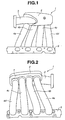
- intake manifold 1 is an inline four-cylinder engine.
- Intake manifold 1 is made of plastic or the like.
- intake manifold 1 includes intake air collector 2 which is elongate and extends along a row of cylinders of engine main body 8.
- Intake air inducting pipe 3 is connected with intake air collector 2.
- Four branch pipes 4a, 4b, 4c and 4d are connected with intake air collector 2.
- intake air is supplied to each cylinder of the engine main body. More specifically, first, second, third, and fourth cylinders C1, C2, C3, C4 are supplied with intake air through branch pipes 4a, 4b, 4c and 4d, respectively.
- intake air is inducted into intake air collector 2.
- Intake air inducting pipe 3 is connected with intake air collector 2 at a side surface opposite to a side surface at which branch pipes 4a to 4d are connected, and on one end side (or left side in Fig. 1 ) of intake air collector 2 in a longitudinal direction of the intake air collector.
- each branch pipe 4a to 4d Through each branch pipe 4a to 4d, intake air within intake air collector 2 is inducted to an intake air entrance (not shown) of the corresponding cylinder C1, C2, C3, C4.
- One end section of each branch pipe extends generally in the same direction to be connected with intake air collector 2.
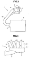
- the side surface F at which each branch pipe 4a to 4d is connected as shown in Fig. 2 and Fig. 3 is formed extending generally along a vertical direction of engine main body 8 (i.e., generally along a vertical direction in Fig. 3 ).
- Each branch pipe 4a t-o 4d is formed to be generally U-shaped as a whole and extends from the intake air entrance opened on the side surface of engine main body 8 toward an upper side of engine main body 8. Therefore, intake air collector 2 is located above engine main body 8.
- the other end section of each branch pipe 4a to 4d is connected with each other by flange 5.
- intake air inducting pipe 3 has intake air inducting pipe opening section 6 at which intake air inducting pipe 3 and intake air collector 2 is connected each other.
- Intake air inducting pipe opening section 6 extends along the longitudinal direction of intake air collector 2.
- Intake air inducting pipe opening section 6 is also located between or bridges branch pipe 4a which is located on one end side of intake air collector 2 and branch pipe 4b which is located adjacent to branch pipe 4a, on a plane of Figs. 1 and 2 .
- intake air inducting pipe opening section 6 is formed to be located between or bridge branch pipe opening 7a which is a junction (section) connecting branch pipe 4a with intake air collector 2 and branch pipe opening 7b which is the junction connecting branch pipe 4b with intake air collector 2, in the longitudinal direction of intake air collector 2.
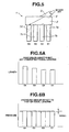
- Fig. 5 is a schematic plan view showing a locational configuration including intake air inducting pipe 3, intake air collector 2 and each branch pipe 4a to 4d.
- intake air inducting pipe opening section 6 has an axis (not shown) which is directed to branch pipe 4d which is nearly located on the other end side (or right side in Fig. 1 ) of intake air collector 2. More specifically, the axis of intake air inducting pipe opening section 6 is inclined to an axis (not shown) of branch pipe 4 as indicated by an arrow in Fig. 5 , on a plane of Fig. 5 .
- the axis of intake air inducting pipe opening section 6 is also formed to be directed to branch pipe opening section 7d which is a junction (section) connecting branch pipe 4d with intake air collector 2. Additionally, 7c denotes a branch pipe opening section which is a junction (section) connecting branch pipe 4c with intake air collector 2.
- intake air passage means a passage through which intake air flows, formed in the air intake structure.
- intake air inducting pipe 3 is connected with intake air collector 2 at a location between branch pipe 4a and branch pipe 4b in the longitudinal direction of intake air collector 2, so that it is possible to decrease a difference in substantial length of the intake air passage among respective cylinders.
- the axis of intake air inducting pipe opening section 6 is directed to branch pipe 4d located the farthest from intake air inducting pipe opening section 6 in the longitudinal direction of intake air collector 2. Therefore, a bend of the intake air inducted from intake air inducting pipe opening section 6 to the branch pipe is increased as,the branch pipe comes close to intake air inducting pipe opening section 6 in the longitudinal direction of intake air collector 2. A pressure loss (or bend loss) generated by the bend of intake air is relatively increased as branch pipe 4 comes close to intake air inducting pipe opening section 6.
- the length from the junction between the branch pipe and intake air collector 2 to intake air inducting pipe opening section 6 become longer as the junction between branch pipe 4 and intake air collector 2 becomes far from intake air inducting pipe opening section 6. Accordingly, a pressure loss (or length loss) generated by the length of the intake air is relatively increased as the branch pipe is far from intake air inducting pipe opening section 6.
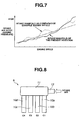
- Fig. 7 differences in the substantial lengths of the intake air passages for the respective cylinders are decreased so that the intake air noise (or sound pressure) generated by differences in the lengths of the intake air passages for the respective cylinders can be effectively decreased as shown in Fig. 7 .
- the sound pressure increases as an engine speed of an engine rises, so that a driver does not receive uncomfortable feeling.
- a solid line indicates measurement result of the intake air noise of the intake manifold of this embodiment
- a dotted line indicates measurement result of another intake manifold A which is a comparative example as shown in Fig. 8 which will be discussed after.
- intake manifold A is different from above-described intake manifold 1 of this embodiment only in location at which the connecting section of intake air inducting pipe 13 is connected to intake air collector 11.
- intake manifold A has a common or usual configuration in which intake air inducting pipe 13 is connected to one end section of intake air collector 11, and each branch pipe 10a to 10d is connected to one side surface of intake air collector 11. Therefore, in this intake manifold A, the substantial lengths of the intake air passages for respective cylinders are not equal, and the peak values of pressure waves generated by the cylinders are not equal to each other as shown in Figs. 9A and 9B . Furthermore, in intake manifold A, sound pressure varies with the engine speed as apparent from Fig. 7 so that the driver may receive uncomfortable feeling.
- intake manifold B as shown in Fig. 10 in which each branch pipe 20 is three-dimensionally independent, generally the same substantial length or distance from the opening section of the branch pipe 20 to the opening section of intake air inducting pipe 23 is obtained for the respective branch pipes 20. Therefore, it is possible to make the substantial lengths of the intake air passages for the respective cylinders generally equal as shown in Fig. 11A . Furthermore, it is possible to make pressure wave generated from each cylinder uniform as shown in Fig. 11B .
- a configuration becomes complicated, thereby raising problems such as limitation in manufacturing method (molding is impossible), lowering in productivity, increase in a production cost and increase in weight.
- intake manifold B constructed of intake air inducting pipe 23, intake air collector 21 and each branch pipe 20 becomes larger in size there by causing deterioration in mount ability to a vehicle or the like.
- intake manifold 1 In contrast to intake manifold B, according to the present invention, it is possible to arrange all branch pipes 4a to 4d in a row along the longitudinal direction of intake air collector 2, so that, it is possible to manufacture intake manifold 1 by using a manufacturing method that is the same as that for intake manifold A as shown in Fig. 8 and different to that for intake manifold B as shown in Fig. 10 , i.e., by using molding. Therefore, productivity of the intake manifold is not sacrificed.
- intake air inducting pipe 33 is connected to intake air collector 31 near the center of the longitudinal direction of intake air collector 31.
- Each branch pipe 30 is connected to a surface that is opposite to a surface at which intake air inducting pipe 33 is connected.
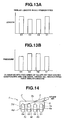
- a width (dimension in vertical direction in Fig. 12 ) of intake manifold C including intake air inducting pipe 33, intake air collector 31 and branch pipes 30 becomes relatively large, thereby causing degradation of the mount ability to the vehicle or the like.
- the peak values of pressure waves generated by the cylinders are classified into two values as shown in Fig. 13B , so that the tone of intake air noise dulls. Therefore, it is impossible to make the intake air noise clear as same as noise generated by intake manifold 1 of this embodiment.
- the intake air structure of this invention is not limited to the above-discussed embodiment. Accordingly, the axis of intake air inducting pipe opening section 6 located at one end side of the intake air collector is directed to the junction between the intake air collector and the branch pipe connected to the intake air collector and located the farthest from the one end side of the intake air collector, and the intake air inducting pipe opening section is located between opening section 7a of first branch pipe 4a placed the nearest to the one end side of the intake air collector and opening section 7b of second branch pipe 4b placed adjacent to the first branch pipe 4a in the longitudinal direction of the intake air collector. Therefore, intake air inducting pipe 3 may be connected with intake air collector 2 from the above side of intake manifold 1 in a vertical direction in Fig. 1 to Fig.
- FIG. 14 showing the air intake structure as another embodiment of the present invention. That is to say, it is possible to connect intake air inducting pipe 3 with intake air collector 2 from the vertical direction or a horizontal direction in Fig. 1 to Fig. 3 .
- the principle of the air intake structure according to this invention is applicable not only to the inline four-cylinder engine but also to engines each of which includes at least one group of the cylinders in which intake manifold is provided for each group of cylinders. More specifically, it is applicable to a first engine having the number (multiple of 4) of cylinders (eight cylinders, twelve cylinders and the like) in which one intake manifold is provided for four cylinders, a second engine having the number (multiple of 3) of cylinders (three cylinders, six cylinders, nine cylinders and the like) in which one intake manifold is provided for three cylinders, and a third engine having the number (multiple of 5) of cylinders (five cylinders, ten cylinders and the like) in which one intake manifold is provided for five cylinders.
- the second and third engines have a little effect for decreasing intake air noise as composed with the first engine.
- these engines can obtain good effects for decreasing intake air noise as compared with engine provided with the above-mentioned intake manifold A.
- the axis of intake air inducting pipe opening section 6 located at one end side of the intake air collector is directed to the junction between the branch pipe connected to the intake air collector and the intake air collector located the farthest from the one end side of the intake air collector, and is located between opening section 7a of first branch pipe 4a placed the nearest to the one end section of the intake air collector and opening section 7b of second branch pipe 4b placed adjacent to the first branch pipe in the longitudinal direction of the intake air collector.
- the intake air inducting pipe opening section may be formed such that its axis is directed to the branch pipe (for example, branch pipe 4c placed secondly nearest to the other end side of the intake air collector) placed at the other end side of the longitudinal direction of the intake air collector in the longitudinal direction, and to be placed between the one branch pipe placed in the one end side of the intake air collector and the next branch pipe placed adjacent to the one branch pipe (for example, between branch pipe 4b placed secondly nearest to the one end side and branch pipe 4c placed thirdly nearest to the one end side of the intake air collector) in the longitudinal direction of the intake air collector.
- branch pipe for example, branch pipe 4c placed secondly nearest to the other end side of the intake air collector
Landscapes
- Engineering & Computer Science (AREA)
- Chemical & Material Sciences (AREA)
- Combustion & Propulsion (AREA)
- Mechanical Engineering (AREA)
- General Engineering & Computer Science (AREA)
- Physics & Mathematics (AREA)
- Geometry (AREA)
- Characterised By The Charging Evacuation (AREA)
Claims (5)
- Lufteinlassanordnung einer Brennkraftmaschine, aufweisend:einen Einassluftsammler (2) mit ersten und zweiten Endseiten, die in Längsrichtung einander gegenüberliegen;ein Einlasslufteinleitungsrohr (3), verbunden mit dem Einassluftsammler (2); undeine Mehrzahl von Abzweigungsrohren (4a-4d), verbunden mit dem Einlassluftsammler (2) und verbunden jeweils mit Einlasslufteingängen der Zylinder (C1-C4) der Brennkraftmaschine, wobei jedes Abzweigungsrohr (4a-4d) durch einen Verbindungsabschnitt des Abzweigungsrohres (4a-4d) mit dem Einassluftsammler (2) verbunden ist, der Verbindungsabschnitt der Abzweigungsrohre (4a-4d) entlang einer Längsrichtung des Einassluftsammlers (2) angeordnet ist, wobei das Einlasslufteinleitungsrohr (3) einen Öffnungsabschnitt (6) hat, der als ein Verbindungsabschnitt des Einlasslufteinleitungsrohres (3) mit dem Einassluftsammler (2) dient, dadurch gekennzeichnet, dass der Öffnungsabschnitt (6), angeordnet ist zwischen oder überbrückt eine Abzweigungsrohröffnung (7a) eines ersten Abzweigungsrohres (4a), angeordnet an der ersten Endseite des Einassluftsammlers (2), und einer Abzweigungsrohröffnung (7b) des zweiten Abzweigungsrohres (4b), angeordnet benachbart zu dem ersten Abzweigungsrohr (4a) in einer Längsrichtung des Einassluftsammlers (2), und eine Achse hat, die zu einer Abzweigungsrohröffnung (7d) eines weiteren Abzweigungsrohres (4d), angeordnet am weitesten entfernt von dem Öffnungsabschnitt (6) des Einlasslufteinleitungsrohres (3) an der zweiten Endseite des Einassluftsammlers (2) gerichtet ist.
- Lufteinlassanordnung nach Anspruch 1, dadurch gekennzeichnet, dass der Einassluftsammler (2), das Einlasslufteinleitungsrohr (3) und die Abzweigungsrohre (4a-4d) einen Einlassverteiler bilden.
- Lufteinlassanordnung nach Anspruch 2, dadurch gekennzeichnet, dass die Zylinder (C1-C4) der Brennkraftmaschine zumindest eine Gruppe von Zylindern enthalten, wobei der Einlassverteiler den Einassluftsammler (2), vorgesehen für jede Gruppe von Zylindern, die Abzweigrohre in einer Anzahl, die einer Zylinderanzahl in jeder Gruppe von Zylindern entspricht, und das Einlasslufteinleitungsrohr enthält.
- Lufteinlassanordnung nach Anspruch 3, dadurch gekennzeichnet, dass jede Zylindergruppe (C1-C4) vier Zylinder enthält.
- Lufteinlassanordnung nach Anspruch 3, dadurch gekennzeichnet, dass jede Zylindergruppe drei Zylinder enthält.
Applications Claiming Priority (2)
| Application Number | Priority Date | Filing Date | Title |
|---|---|---|---|
| JP2003351583 | 2003-10-10 | ||
| JP2003351583A JP4214883B2 (ja) | 2003-10-10 | 2003-10-10 | 内燃機関の吸気構造 |
Publications (3)
| Publication Number | Publication Date |
|---|---|
| EP1522716A2 EP1522716A2 (de) | 2005-04-13 |
| EP1522716A3 EP1522716A3 (de) | 2010-04-28 |
| EP1522716B1 true EP1522716B1 (de) | 2012-08-01 |
Family
ID=34309272
Family Applications (1)
| Application Number | Title | Priority Date | Filing Date |
|---|---|---|---|
| EP04023975A Expired - Lifetime EP1522716B1 (de) | 2003-10-10 | 2004-10-07 | Struktur des Lufteinlasses einer Brennkraftmaschine |
Country Status (4)
| Country | Link |
|---|---|
| US (1) | US6920858B2 (de) |
| EP (1) | EP1522716B1 (de) |
| JP (1) | JP4214883B2 (de) |
| CN (1) | CN100339588C (de) |
Families Citing this family (5)
| Publication number | Priority date | Publication date | Assignee | Title |
|---|---|---|---|---|
| US7401590B2 (en) * | 2006-10-09 | 2008-07-22 | Harley-Davidson Motor Company Group, Inc. | Active air intake for an engine |
| JP4906549B2 (ja) * | 2007-03-15 | 2012-03-28 | 本田技研工業株式会社 | 多気筒内燃機関の吸気マニホルド |
| FR2920487A1 (fr) * | 2007-09-05 | 2009-03-06 | Renault Sas | Repartiteur d'air de ligne d'admission d'air accorde acoustiquement |
| CN103603755A (zh) * | 2013-12-05 | 2014-02-26 | 安徽江淮汽车股份有限公司 | 一种车用汽油机的进气歧管 |
| JP2019157774A (ja) * | 2018-03-14 | 2019-09-19 | アイシン精機株式会社 | 吸気装置および吸気装置の製造方法 |
Family Cites Families (9)
| Publication number | Priority date | Publication date | Assignee | Title |
|---|---|---|---|---|
| JP2850596B2 (ja) * | 1991-10-14 | 1999-01-27 | トヨタ自動車株式会社 | 多気筒内燃機関の吸気装置 |
| US5623900A (en) * | 1992-08-22 | 1997-04-29 | Dr. Ing. H.C.F. Porsche Ag | Internal-combustion engine comprising an intake system |
| DE59206260D1 (de) * | 1992-08-22 | 1996-06-13 | Porsche Ag | Brennkraftmaschine mit einer ansauganlage |
| RU2107182C1 (ru) * | 1992-08-22 | 1998-03-20 | Акционерное общество "АвтоВАЗ" | Впускное устройство для двигателя внутреннего сгорания |
| JP3383337B2 (ja) | 1992-12-14 | 2003-03-04 | 株式会社エッチ・ケー・エス | 吸気コレクタ |
| JPH08105359A (ja) | 1994-10-07 | 1996-04-23 | Nissan Motor Co Ltd | 内燃機関の吸気マニホールド装置 |
| JP3562031B2 (ja) * | 1995-06-08 | 2004-09-08 | 日産自動車株式会社 | 内燃機関の吸気マニホルド一体型ロッカカバー |
| DE19803804A1 (de) * | 1998-01-31 | 1999-08-05 | Volkswagen Ag | Sauganlage zur Verbrennungsluftversorgung einer Brennkraftmaschine |
| JP2002168153A (ja) * | 2000-12-01 | 2002-06-14 | Denso Corp | 内燃機関用吸気装置 |
-
2003
- 2003-10-10 JP JP2003351583A patent/JP4214883B2/ja not_active Expired - Fee Related
-
2004
- 2004-10-07 EP EP04023975A patent/EP1522716B1/de not_active Expired - Lifetime
- 2004-10-07 US US10/959,579 patent/US6920858B2/en not_active Expired - Fee Related
- 2004-10-10 CN CNB2004100849344A patent/CN100339588C/zh not_active Expired - Fee Related
Also Published As
| Publication number | Publication date |
|---|---|
| JP2005113852A (ja) | 2005-04-28 |
| US6920858B2 (en) | 2005-07-26 |
| CN1605742A (zh) | 2005-04-13 |
| CN100339588C (zh) | 2007-09-26 |
| EP1522716A2 (de) | 2005-04-13 |
| US20050076872A1 (en) | 2005-04-14 |
| EP1522716A3 (de) | 2010-04-28 |
| JP4214883B2 (ja) | 2009-01-28 |
Similar Documents
| Publication | Publication Date | Title |
|---|---|---|
| KR101738249B1 (ko) | 통합된 잡음 억제를 이용하는 열 교환기 | |
| US8047177B2 (en) | Cylinder head having an integrally formed port-exhaust manifold assembly | |
| US20050115231A1 (en) | Exhaust manifold for internal combustion engine | |
| US4686944A (en) | Intake manifold structure for V-type engine | |
| EP1522716B1 (de) | Struktur des Lufteinlasses einer Brennkraftmaschine | |
| US6038855A (en) | Collector device for the primary pipes of an exhaust manifold | |
| US6357411B1 (en) | Intake device for internal combustion engines | |
| US6994065B2 (en) | Intake arrangement for internal combustion engine | |
| CN1696480B (zh) | 多缸发动机进气系统 | |
| JP2008223738A (ja) | 多気筒内燃機関の吸気マニホルド | |
| JP4075761B2 (ja) | 内燃機関の吸気装置 | |
| US6978606B2 (en) | Equal length crossover pipe exhaust system | |
| JP3081441B2 (ja) | エンジン用吸気マニホールド構造 | |
| JP2000161163A (ja) | 多気筒内燃機関における慣性過給式吸気マニホールドの構造 | |
| JP3062257B2 (ja) | エンジンの吸気装置 | |
| JP2813190B2 (ja) | 多気筒エンジンの排気装置 | |
| JP3485156B2 (ja) | 多気筒内燃機関における慣性過給式吸気マニホールドの構造 | |
| JP2009156149A (ja) | 吸気マニホールド | |
| JPH0240021A (ja) | V型エンジンの吸気構造 | |
| JP2970230B2 (ja) | 車輌用デュアル排気管 | |
| JPH0430337Y2 (de) | ||
| JPH0247234Y2 (de) | ||
| JPH0528378Y2 (de) | ||
| JPH0738661Y2 (ja) | エンジンの吸気装置 | |
| JPH03160111A (ja) | 内燃機関における慣性過給式吸気マニホールド |
Legal Events
| Date | Code | Title | Description |
|---|---|---|---|
| PUAI | Public reference made under article 153(3) epc to a published international application that has entered the european phase |
Free format text: ORIGINAL CODE: 0009012 |
|
| 17P | Request for examination filed |
Effective date: 20041007 |
|
| AK | Designated contracting states |
Kind code of ref document: A2 Designated state(s): AT BE BG CH CY CZ DE DK EE ES FI FR GB GR HU IE IT LI LU MC NL PL PT RO SE SI SK TR |
|
| AX | Request for extension of the european patent |
Extension state: AL HR LT LV MK |
|
| PUAL | Search report despatched |
Free format text: ORIGINAL CODE: 0009013 |
|
| AK | Designated contracting states |
Kind code of ref document: A3 Designated state(s): AT BE BG CH CY CZ DE DK EE ES FI FR GB GR HU IE IT LI LU MC NL PL PT RO SE SI SK TR |
|
| AX | Request for extension of the european patent |
Extension state: AL HR LT LV MK |
|
| RIC1 | Information provided on ipc code assigned before grant |
Ipc: F02M 35/10 20060101AFI20041111BHEP Ipc: F02M 35/104 20060101ALI20100323BHEP Ipc: F02M 35/112 20060101ALI20100323BHEP |
|
| AKX | Designation fees paid |
Designated state(s): DE FR GB |
|
| 17Q | First examination report despatched |
Effective date: 20110311 |
|
| GRAP | Despatch of communication of intention to grant a patent |
Free format text: ORIGINAL CODE: EPIDOSNIGR1 |
|
| GRAS | Grant fee paid |
Free format text: ORIGINAL CODE: EPIDOSNIGR3 |
|
| GRAA | (expected) grant |
Free format text: ORIGINAL CODE: 0009210 |
|
| AK | Designated contracting states |
Kind code of ref document: B1 Designated state(s): DE FR GB |
|
| REG | Reference to a national code |
Ref country code: GB Ref legal event code: FG4D |
|
| RAP1 | Party data changed (applicant data changed or rights of an application transferred) |
Owner name: NISSAN MOTOR CO., LTD. |
|
| REG | Reference to a national code |
Ref country code: DE Ref legal event code: R096 Ref document number: 602004038704 Country of ref document: DE Effective date: 20120927 |
|
| PLBE | No opposition filed within time limit |
Free format text: ORIGINAL CODE: 0009261 |
|
| STAA | Information on the status of an ep patent application or granted ep patent |
Free format text: STATUS: NO OPPOSITION FILED WITHIN TIME LIMIT |
|
| 26N | No opposition filed |
Effective date: 20130503 |
|
| REG | Reference to a national code |
Ref country code: DE Ref legal event code: R097 Ref document number: 602004038704 Country of ref document: DE Effective date: 20130503 |
|
| PGFP | Annual fee paid to national office [announced via postgrant information from national office to epo] |
Ref country code: GB Payment date: 20131002 Year of fee payment: 10 Ref country code: FR Payment date: 20131009 Year of fee payment: 10 Ref country code: DE Payment date: 20131002 Year of fee payment: 10 |
|
| REG | Reference to a national code |
Ref country code: DE Ref legal event code: R119 Ref document number: 602004038704 Country of ref document: DE |
|
| GBPC | Gb: european patent ceased through non-payment of renewal fee |
Effective date: 20141007 |
|
| PG25 | Lapsed in a contracting state [announced via postgrant information from national office to epo] |
Ref country code: GB Free format text: LAPSE BECAUSE OF NON-PAYMENT OF DUE FEES Effective date: 20141007 Ref country code: DE Free format text: LAPSE BECAUSE OF NON-PAYMENT OF DUE FEES Effective date: 20150501 |
|
| REG | Reference to a national code |
Ref country code: FR Ref legal event code: ST Effective date: 20150630 |
|
| PG25 | Lapsed in a contracting state [announced via postgrant information from national office to epo] |
Ref country code: FR Free format text: LAPSE BECAUSE OF NON-PAYMENT OF DUE FEES Effective date: 20141031 |