EP1522669A2 - Geradverbinder aus Kunststoff zur Verbindung von Rahmenhohlprofilen für Isolierglasscheiben - Google Patents
Geradverbinder aus Kunststoff zur Verbindung von Rahmenhohlprofilen für Isolierglasscheiben Download PDFInfo
- Publication number
- EP1522669A2 EP1522669A2 EP04017507A EP04017507A EP1522669A2 EP 1522669 A2 EP1522669 A2 EP 1522669A2 EP 04017507 A EP04017507 A EP 04017507A EP 04017507 A EP04017507 A EP 04017507A EP 1522669 A2 EP1522669 A2 EP 1522669A2
- Authority
- EP
- European Patent Office
- Prior art keywords
- straight connector
- connector according
- lamellae
- slats
- base body
- Prior art date
- Legal status (The legal status is an assumption and is not a legal conclusion. Google has not performed a legal analysis and makes no representation as to the accuracy of the status listed.)
- Granted
Links
- 241000446313 Lamella Species 0.000 claims description 2
- 239000011521 glass Substances 0.000 claims description 2
- 239000000463 material Substances 0.000 description 4
- 230000000694 effects Effects 0.000 description 3
- 230000008901 benefit Effects 0.000 description 2
- 238000003780 insertion Methods 0.000 description 2
- 230000037431 insertion Effects 0.000 description 2
- 238000012986 modification Methods 0.000 description 2
- 230000004048 modification Effects 0.000 description 2
- 230000009286 beneficial effect Effects 0.000 description 1
- 238000010276 construction Methods 0.000 description 1
- 230000001419 dependent effect Effects 0.000 description 1
- 238000001035 drying Methods 0.000 description 1
- 238000000605 extraction Methods 0.000 description 1
- 230000002349 favourable effect Effects 0.000 description 1
- 238000004519 manufacturing process Methods 0.000 description 1
- 239000006228 supernatant Substances 0.000 description 1
Images

Classifications
-
- E—FIXED CONSTRUCTIONS
- E06—DOORS, WINDOWS, SHUTTERS, OR ROLLER BLINDS IN GENERAL; LADDERS
- E06B—FIXED OR MOVABLE CLOSURES FOR OPENINGS IN BUILDINGS, VEHICLES, FENCES OR LIKE ENCLOSURES IN GENERAL, e.g. DOORS, WINDOWS, BLINDS, GATES
- E06B3/00—Window sashes, door leaves, or like elements for closing wall or like openings; Layout of fixed or moving closures, e.g. windows in wall or like openings; Features of rigidly-mounted outer frames relating to the mounting of wing frames
- E06B3/66—Units comprising two or more parallel glass or like panes permanently secured together
- E06B3/663—Elements for spacing panes
- E06B3/667—Connectors therefor
Definitions
- the invention relates to a straight connector after Preamble of the main claim.
- the invention relates to a straight connector made of plastic, with the help of which frame hollow profiles for insulating glass panes are connectable.
- the straight connector an elongated body on whose opposite End portions can each be inserted into a hollow profile are, wherein the base body provided with at least one longitudinal groove is to the passage of hygroscopic material too enable.
- the main body has deformable to its anchorage Slats or teeth on, with the help of which he in the Frame hollow profile is held.
- Such a straight connector is for example from DE 94 02 693 U1 previously known.
- the straight connectors must be designed so that these over a longer period firmly seated in the frame hollow profile are held. This longer period is the Period from the production of the hollow frame profile to its Use in a glaziery or window shop. at Straight connectors, which are not tight, are in danger of that they fall out and get lost and / or at one only partly inserted state under mechanical loads damage the end area of the frame hollow profile.
- the invention is based on the object, a straight connector to create the type mentioned, which in a simple Structure and simple, cost-effective manufacturability a high Holding force and extraction force even after a long period of time having.
- the basic body a base surface provided with two spaced longitudinal grooves is, in which the slats arranged upright or standing are.
- the straight connector according to the invention is characterized by a Series of significant benefits.
- the slats By the arrangement of the slats in the longitudinal grooves of the base surface the possibility is created that will last long enough Slats are provided, which can deform accordingly, to anchor the straight connector in the frame hollow profile. According to the invention, there is thus a wedging or clawing the slats. This differs significantly from State of the art. There, the slats are only against pressed the wall of the frame hollow profile, so that a Holder only by friction when applying the slats of the slats he follows. At the same time, the base area serves as safe Attachment, allowing a twisting or tilting of the straight connector can be reliably avoided.
- Another major advantage is that the two longitudinal grooves with the slats create the possibility the overall profile of the straight connector in such a way that the Longitudinal groove for receiving or carrying the hygroscopic Material can have a sufficient cross-section.
- the lamellae protrude over the base surface.
- the Total amount of this supernatant is preferably 0.2 mm. This is sufficient clawing or wedging ensures the slats, without this too much in the Insertion of the straight connector would be deformed and loaded.
- the mutual Distance of the slats in a range of 1.5 to 2 mm is located.
- a particularly preferred value is at a distance offered by 1.75 mm. Ensure the distances of the slats sufficient clawing on the with features, nubs or other roughness provided inner surface of the frame hollow profile. Since such frame hollow profiles of different Supplied to manufacturers in different designs be, results in the lamella construction according to the invention always a sufficient holding power.
- the slats at their free End are each cut-shaped. This results a particularly high surface pressure, which leads to a Clawing and tilting of the slats leads.
- the main body is in a favorable embodiment substantially rectangular, i. provided with a rectangular outer contour, so not only the base area but also the others Side surfaces abut against the inner wall of the frame hollow profile.
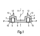
- the straight connector comprises a base body 1, which with a front end portion 2 and a rear End region 3 is provided.
- the straight connector is around a transverse to the longitudinal direction of symmetry plane 10 symmetrical built up.
- the main body comprises a longitudinal groove 4, which extends over the entire length extends and the passage of a hygroscopic Material for drying an insulating middle space allows.
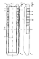
- a base surface 6 of the main body 1 On a base surface 6 of the main body 1 are longitudinal grooves. 7 and 8 are formed, which is a substantially rectangular Have cross-section and in which a number of slats 5 are arranged are each extending vertically outwards, as shown for example in FIG. 3 is.
- the fins 5 are integrally connected to the base body 1.
- the slats are arranged "upright" to the base body 1. They thus extend at right angles to the longitudinal plane of the main body 1 and are inserted into the Frame hollow profile deformed accordingly to the wedge effect (see above) to realize.
- the slats 5 each have one Cut 9, extending through a corresponding bevel results.
- the cutting edge 9 is used for optimal clawing the wall of the frame hollow profile, not shown.
- Fig. 1 is a sectional view along the arrows of FIG. 4th
- slats protrude over the surface of the base surface 6, preferably by an amount of 0.2 mm.
- the side walls 15, 16 of the main body 1 are slightly behind tilted outwardly, as shown in FIG. 1 can be seen.
- Farther are the side walls, as shown in Fig. 4, by a Slit or groove 14 is severed.
- the slot 14 extends down to the respective longitudinal groove 7 and 8.
- the corresponding side of the straight connector can thus be introduced into the frame hollow profile.
- the Edge of the frame hollow profile reaches the slot 14, butts this against the wall of the slot 14.
- This forms together with the elasticity of the side walls 15, 16 a Center stop when inserting the straight connector.
- the deformation the side walls 15, 16 in the direction of the arrows P leads to a slight reduction in the width of the Longitudinal grooves 7, 8. However, this reduction is so small that the functionality of the slats 5 and their Mobility is not affected.
- the free end of the end portions 2 and 3 can be chamfered, rounded or provided with a groove-like recess be as shown in particular in Figs. 2 and 4 is.
Landscapes
- Engineering & Computer Science (AREA)
- Civil Engineering (AREA)
- Structural Engineering (AREA)
- Wing Frames And Configurations (AREA)
- Securing Of Glass Panes Or The Like (AREA)
- Connector Housings Or Holding Contact Members (AREA)
- Mutual Connection Of Rods And Tubes (AREA)
- Connections Effected By Soldering, Adhesion, Or Permanent Deformation (AREA)
- Joining Of Corner Units Of Frames Or Wings (AREA)
Abstract
Description
- Fig. 1
- eine vereinfachte Schnittansicht eines erfindungsgemäßen Geradverbinders,
- Fig. 2
- eine Unteransicht des in Fig. 1 gezeigten Ausführungsbeispiels,
- Fig. 3
- eine Seitenansicht, teils im Schnitt, des erfindungsgemäßen Geradverbinders, und
- Fig. 4
- eine Draufsicht auf den erfindungsgemäßen Geradverbinder.
- 1
- Grundkörper
- 2
- Endbereich
- 3
- Endbereich
- 4
- Längsnut
- 5
- Lamellen
- 6
- Basisfläche
- 7
- Längsnut
- 8
- Längsnut
- 9
- Schneide
- 10
- Symmetrieebene
- 11
- Symmetrieebene
- 12
- Hohlkehle
- 13
- Anlagekante
- 14
- Schlitz
- 15
- Seitenwandung
- 16
- Seitenwandung
- A
- Abstand
- P
- Pfeil
Claims (8)
- Geradverbinder aus Kunststoff zur Verbindung von Rahmenhohlprofilen für Isolierglasscheiben mit einem länglichen Grundkörper (1), dessen gegenüberliegende Endbereiche (2, 3) jeweils in ein Hohlprofil einsteckbar sind, wobei der Grundkörper (1) mit einer Längsnut (4) versehen ist und verformbare Lamellen (5) zur Halterung an dem Rahmenhohlprofil aufweist, dadurch gekennzeichnet, dass der Grundkörper (1) an einer Basisfläche (6) mit zwei beabstandeten Längsnuten (7, 8) versehen ist, in welchen die Lamellen (5) angeordnet sind.
- Geradverbinder nach Anspruch 1, dadurch gekennzeichnet, dass die Lamellen (5) über die Basisfläche (6) vorstehen.
- Geradverbinder nach Anspruch 2, dadurch gekennzeichnet, dass die Lamellen (5) über die Basisfläche (6) um 0,2 mm vorstehen.
- Geradverbinder nach einem der Ansprüche 1 bis 3, dadurch gekennzeichnet, dass die Lamellen (5) einen gegenseitigen Abstand von 1,5 bis 2 mm aufweisen.
- Geradverbinder nach Anspruch 4, dadurch gekennzeichnet, dass die Lamellen (5) einen gegenseitigen Abstand von 1,75 mm aufweisen.
- Geradverbinder nach einem der Ansprüche 1 bis 5, dadurch gekennzeichnet, dass die Lamellen (5) an ihrem freien Ende schneidenförmig (9) ausgebildet sind.
- Geradverbinder nach einem der Ansprüche 1 bis 6, dadurch gekennzeichnet, dass der Grundkörper (1) eine im Wesentlichen rechteckige Außenkontur aufweist.
- Geradverbinder nach einem der Ansprüche 1 bis 7, dadurch gekennzeichnet, dass der Grundkörper (1) mit einem Mittelanschlag versehen ist.
Priority Applications (1)
| Application Number | Priority Date | Filing Date | Title |
|---|---|---|---|
| PL04017507T PL1522669T3 (pl) | 2003-10-06 | 2004-07-23 | Prosty łącznik z tworzywa sztucznego do połączenia wydrążonych profili ramowych do paneli ze szkła izolacyjnego |
Applications Claiming Priority (2)
| Application Number | Priority Date | Filing Date | Title |
|---|---|---|---|
| DE10346306A DE10346306B4 (de) | 2003-10-06 | 2003-10-06 | Garadverbinder aus Kunststoff zur Verbindung von Rahmenhohlprofilen für Isolierglasscheiben |
| DE10346306 | 2003-10-06 |
Publications (3)
| Publication Number | Publication Date |
|---|---|
| EP1522669A2 true EP1522669A2 (de) | 2005-04-13 |
| EP1522669A3 EP1522669A3 (de) | 2006-07-05 |
| EP1522669B1 EP1522669B1 (de) | 2008-11-05 |
Family
ID=34306284
Family Applications (1)
| Application Number | Title | Priority Date | Filing Date |
|---|---|---|---|
| EP04017507A Expired - Lifetime EP1522669B1 (de) | 2003-10-06 | 2004-07-23 | Geradverbinder aus Kunststoff zur Verbindung von Rahmenhohlprofilen für Isolierglasscheiben |
Country Status (6)
| Country | Link |
|---|---|
| EP (1) | EP1522669B1 (de) |
| AT (1) | ATE413510T1 (de) |
| DE (2) | DE10346306B4 (de) |
| DK (1) | DK1522669T3 (de) |
| ES (1) | ES2316901T3 (de) |
| PL (1) | PL1522669T3 (de) |
Cited By (3)
| Publication number | Priority date | Publication date | Assignee | Title |
|---|---|---|---|---|
| EP2031171A3 (de) * | 2007-08-29 | 2009-10-28 | astec GmbH | Rahmenlose Glasschiebetür |
| US8240107B2 (en) | 2005-08-01 | 2012-08-14 | Technoform Glass Insulation Holding Gmbh | Spacer arrangement with fusable connector for insulating glass units |
| US20240200402A1 (en) * | 2022-12-15 | 2024-06-20 | Marhaygue, Llc | Multiple component frame and screen system and method |
Families Citing this family (2)
| Publication number | Priority date | Publication date | Assignee | Title |
|---|---|---|---|---|
| EP4702211A1 (de) | 2023-04-26 | 2026-03-04 | Ralf M. Kronenberg | Steckverbinder und steckverbindung |
| DE202023102210U1 (de) | 2023-04-26 | 2024-07-26 | Ralf M. Kronenberg | Steckverbinder |
Citations (1)
| Publication number | Priority date | Publication date | Assignee | Title |
|---|---|---|---|---|
| DE9402693U1 (de) | 1994-02-18 | 1994-04-14 | Cera Handelsgesellschaft Mbh, 87640 Biessenhofen | Geradverbinder aus Kunststoff zur Verbindung von hohlen Abstandsprofilen oder hohlen Sprossenprofilen von Mehrscheibenisoliergläsern |
Family Cites Families (8)
| Publication number | Priority date | Publication date | Assignee | Title |
|---|---|---|---|---|
| DE2307595A1 (de) * | 1973-02-16 | 1974-08-29 | Guenter Dr-Ing Koepke | Distanzelemente fuer fenster, tueren und/ oder aehnliche bauelemente aus kunststoffhohlprofilen, insbesondere fuer deren verstaerkungswinkel und/oder -profile |
| IT8421613U1 (it) * | 1984-04-20 | 1985-10-20 | Laval Lavorazioni Alluminio S P A | Giunzione con inserto a squadra per il collegamento di profilati di telai di doppi vetri. |
| ATE181586T1 (de) * | 1994-06-15 | 1999-07-15 | Cera Handels Gmbh | Linearverbinder für hohle abstandsprofile eines mehrscheibenisolierglases |
| DE9412570U1 (de) * | 1994-08-04 | 1994-10-20 | Schmitz, Werner, Dipl.-Ing., 33014 Bad Driburg | Steckverbinder für Isolierglasscheiben-Abstandshalter |
| DE19522505C2 (de) * | 1995-06-21 | 2001-03-22 | Cera Handels Gmbh | Linearverbinder aus Kunststoff zur Verbindung von hohlen Abstandhalterprofilen von Mehrscheibenisoliergläsern |
| DE29918002U1 (de) * | 1999-10-12 | 2000-01-20 | CERA Handels GmbH, 87600 Kaufbeuren | Linearverbinder aus Kunststoff für Abstandhalterprofile von Mehrscheibenisoliergläsern |
| DE29913903U1 (de) * | 1999-08-10 | 1999-11-25 | CERA Handels GmbH, 87600 Kaufbeuren | Linearverbinder aus Kunststoff für Abstandhalterprofile von Mehrscheibenisoliergläsern |
| DE29921227U1 (de) * | 1999-12-02 | 2000-03-02 | CERA Handels GmbH, 87600 Kaufbeuren | Linearverbinder aus Kunststoff für Abstandhalterrahmen von Mehrscheibenisoliergläsern |
-
2003
- 2003-10-06 DE DE10346306A patent/DE10346306B4/de not_active Expired - Lifetime
-
2004
- 2004-07-23 EP EP04017507A patent/EP1522669B1/de not_active Expired - Lifetime
- 2004-07-23 AT AT04017507T patent/ATE413510T1/de active
- 2004-07-23 DK DK04017507T patent/DK1522669T3/da active
- 2004-07-23 ES ES04017507T patent/ES2316901T3/es not_active Expired - Lifetime
- 2004-07-23 PL PL04017507T patent/PL1522669T3/pl unknown
- 2004-07-23 DE DE502004008392T patent/DE502004008392D1/de not_active Expired - Lifetime
Patent Citations (1)
| Publication number | Priority date | Publication date | Assignee | Title |
|---|---|---|---|---|
| DE9402693U1 (de) | 1994-02-18 | 1994-04-14 | Cera Handelsgesellschaft Mbh, 87640 Biessenhofen | Geradverbinder aus Kunststoff zur Verbindung von hohlen Abstandsprofilen oder hohlen Sprossenprofilen von Mehrscheibenisoliergläsern |
Cited By (3)
| Publication number | Priority date | Publication date | Assignee | Title |
|---|---|---|---|---|
| US8240107B2 (en) | 2005-08-01 | 2012-08-14 | Technoform Glass Insulation Holding Gmbh | Spacer arrangement with fusable connector for insulating glass units |
| EP2031171A3 (de) * | 2007-08-29 | 2009-10-28 | astec GmbH | Rahmenlose Glasschiebetür |
| US20240200402A1 (en) * | 2022-12-15 | 2024-06-20 | Marhaygue, Llc | Multiple component frame and screen system and method |
Also Published As
| Publication number | Publication date |
|---|---|
| EP1522669B1 (de) | 2008-11-05 |
| EP1522669A3 (de) | 2006-07-05 |
| DE502004008392D1 (de) | 2008-12-18 |
| DK1522669T3 (da) | 2009-02-16 |
| ATE413510T1 (de) | 2008-11-15 |
| PL1522669T3 (pl) | 2009-04-30 |
| ES2316901T3 (es) | 2009-04-16 |
| DE10346306A1 (de) | 2005-05-12 |
| DE10346306B4 (de) | 2005-09-01 |
Similar Documents
| Publication | Publication Date | Title |
|---|---|---|
| DE2306969C3 (de) | Klemmvorrichtung zur Befestigung langgestreckter Körper | |
| DE3927979C5 (de) | Gestell aus lösbar durch einen Verbinder miteinander kuppelbaren Profilstangen | |
| WO2008028812A1 (de) | Schubkasten | |
| DE10346306B4 (de) | Garadverbinder aus Kunststoff zur Verbindung von Rahmenhohlprofilen für Isolierglasscheiben | |
| WO2004029465A2 (de) | Verbindungseinrichtung für zwei werkstücke, insbesondere für strangartige hohlprofile | |
| EP1522668B1 (de) | Verbinder für Doppelfenster-Rahmenprofile | |
| DE102015116421A1 (de) | Kippdübel | |
| DE102012004043B4 (de) | Einsteckbauteil, insbesondere Einsteckverbinder für Hohlprofile | |
| DE102011055539A1 (de) | Steckverbinder | |
| DE29921227U1 (de) | Linearverbinder aus Kunststoff für Abstandhalterrahmen von Mehrscheibenisoliergläsern | |
| DE602005003380T2 (de) | Verfahren zur Montage eines Verstärkungsteils auf die Frontplatte eines Kühl- oder Gefrierschrankes | |
| DE20018012U1 (de) | Endstopfen zum Anschrauben von Sprossen an Abstandhalterrahmen von insbesondere Isolierglasscheiben | |
| DE2621979B2 (de) | Vielfachsteckverbinder | |
| EP2886778B1 (de) | Eckverbinder geknickter Draht | |
| EP2594722B1 (de) | Steckverbinder | |
| DE102004004405A1 (de) | Borstenstreifen für ein Reinigungsgerät | |
| EP0710762B1 (de) | Linearverbinder für hohle Abstandsprofile eines Mehrscheibenisolierglases | |
| EP0439062A1 (de) | Profilsystem | |
| DE4429078C2 (de) | Verbinder | |
| DE4013513C2 (de) | Steckverbinder für die geradlinige Stoßverbindung zweier Hohlprofile | |
| DE102016001091B3 (de) | Trainingsgerät für Sportübungen | |
| EP0028733A1 (de) | Rolladen, Verfahren zur Herstellung desselben und Hohlprofilstab für Rolladen | |
| DE8530343U1 (de) | Schutzhülle aus Kunststoff für Scheckkarten, Kreditkarten, od. dgl. | |
| DE2158386C3 (de) | Verteilungssystem für elektrische Energie | |
| DE2216327A1 (de) | Montagezange fuer sprengringe |
Legal Events
| Date | Code | Title | Description |
|---|---|---|---|
| PUAI | Public reference made under article 153(3) epc to a published international application that has entered the european phase |
Free format text: ORIGINAL CODE: 0009012 |
|
| AK | Designated contracting states |
Kind code of ref document: A2 Designated state(s): AT BE BG CH CY CZ DE DK EE ES FI FR GB GR HU IE IT LI LU MC NL PL PT RO SE SI SK TR |
|
| AX | Request for extension of the european patent |
Extension state: AL HR LT LV MK |
|
| PUAL | Search report despatched |
Free format text: ORIGINAL CODE: 0009013 |
|
| AK | Designated contracting states |
Kind code of ref document: A3 Designated state(s): AT BE BG CH CY CZ DE DK EE ES FI FR GB GR HU IE IT LI LU MC NL PL PT RO SE SI SK TR |
|
| AX | Request for extension of the european patent |
Extension state: AL HR LT LV MK |
|
| 17P | Request for examination filed |
Effective date: 20060807 |
|
| AKX | Designation fees paid |
Designated state(s): AT BE BG CH CY CZ DE DK EE ES FI FR GB GR HU IE IT LI LU MC NL PL PT RO SE SI SK TR |
|
| 17Q | First examination report despatched |
Effective date: 20071106 |
|
| GRAP | Despatch of communication of intention to grant a patent |
Free format text: ORIGINAL CODE: EPIDOSNIGR1 |
|
| RAP1 | Party data changed (applicant data changed or rights of an application transferred) |
Owner name: MAX KRONENBERG UND RALF M. KRONENBERG GBR |
|
| GRAS | Grant fee paid |
Free format text: ORIGINAL CODE: EPIDOSNIGR3 |
|
| GRAA | (expected) grant |
Free format text: ORIGINAL CODE: 0009210 |
|
| AK | Designated contracting states |
Kind code of ref document: B1 Designated state(s): AT BE BG CH CY CZ DE DK EE ES FI FR GB GR HU IE IT LI LU MC NL PL PT RO SE SI SK TR |
|
| REG | Reference to a national code |
Ref country code: GB Ref legal event code: FG4D Free format text: NOT ENGLISH |
|
| REG | Reference to a national code |
Ref country code: CH Ref legal event code: NV Representative=s name: E. BLUM & CO. AG PATENT- UND MARKENANWAELTE VSP Ref country code: CH Ref legal event code: EP |
|
| REG | Reference to a national code |
Ref country code: IE Ref legal event code: FG4D Free format text: LANGUAGE OF EP DOCUMENT: GERMAN |
|
| REF | Corresponds to: |
Ref document number: 502004008392 Country of ref document: DE Date of ref document: 20081218 Kind code of ref document: P |
|
| REG | Reference to a national code |
Ref country code: DK Ref legal event code: T3 |
|
| REG | Reference to a national code |
Ref country code: GR Ref legal event code: EP Ref document number: 20090400354 Country of ref document: GR |
|
| REG | Reference to a national code |
Ref country code: ES Ref legal event code: FG2A Ref document number: 2316901 Country of ref document: ES Kind code of ref document: T3 |
|
| REG | Reference to a national code |
Ref country code: PL Ref legal event code: T3 |
|
| PG25 | Lapsed in a contracting state [announced via postgrant information from national office to epo] |
Ref country code: SI Free format text: LAPSE BECAUSE OF FAILURE TO SUBMIT A TRANSLATION OF THE DESCRIPTION OR TO PAY THE FEE WITHIN THE PRESCRIBED TIME-LIMIT Effective date: 20081105 |
|
| REG | Reference to a national code |
Ref country code: IE Ref legal event code: FD4D |
|
| PG25 | Lapsed in a contracting state [announced via postgrant information from national office to epo] |
Ref country code: RO Free format text: LAPSE BECAUSE OF FAILURE TO SUBMIT A TRANSLATION OF THE DESCRIPTION OR TO PAY THE FEE WITHIN THE PRESCRIBED TIME-LIMIT Effective date: 20081105 Ref country code: IE Free format text: LAPSE BECAUSE OF FAILURE TO SUBMIT A TRANSLATION OF THE DESCRIPTION OR TO PAY THE FEE WITHIN THE PRESCRIBED TIME-LIMIT Effective date: 20081105 Ref country code: EE Free format text: LAPSE BECAUSE OF FAILURE TO SUBMIT A TRANSLATION OF THE DESCRIPTION OR TO PAY THE FEE WITHIN THE PRESCRIBED TIME-LIMIT Effective date: 20081105 Ref country code: BG Free format text: LAPSE BECAUSE OF FAILURE TO SUBMIT A TRANSLATION OF THE DESCRIPTION OR TO PAY THE FEE WITHIN THE PRESCRIBED TIME-LIMIT Effective date: 20090205 |
|
| REG | Reference to a national code |
Ref country code: HU Ref legal event code: AG4A Ref document number: E005379 Country of ref document: HU |
|
| PG25 | Lapsed in a contracting state [announced via postgrant information from national office to epo] |
Ref country code: SE Free format text: LAPSE BECAUSE OF FAILURE TO SUBMIT A TRANSLATION OF THE DESCRIPTION OR TO PAY THE FEE WITHIN THE PRESCRIBED TIME-LIMIT Effective date: 20090205 Ref country code: PT Free format text: LAPSE BECAUSE OF FAILURE TO SUBMIT A TRANSLATION OF THE DESCRIPTION OR TO PAY THE FEE WITHIN THE PRESCRIBED TIME-LIMIT Effective date: 20090406 |
|
| PLBE | No opposition filed within time limit |
Free format text: ORIGINAL CODE: 0009261 |
|
| STAA | Information on the status of an ep patent application or granted ep patent |
Free format text: STATUS: NO OPPOSITION FILED WITHIN TIME LIMIT |
|
| PG25 | Lapsed in a contracting state [announced via postgrant information from national office to epo] |
Ref country code: SK Free format text: LAPSE BECAUSE OF FAILURE TO SUBMIT A TRANSLATION OF THE DESCRIPTION OR TO PAY THE FEE WITHIN THE PRESCRIBED TIME-LIMIT Effective date: 20081105 |
|
| 26N | No opposition filed |
Effective date: 20090806 |
|
| PG25 | Lapsed in a contracting state [announced via postgrant information from national office to epo] |
Ref country code: MC Free format text: LAPSE BECAUSE OF NON-PAYMENT OF DUE FEES Effective date: 20090731 |
|
| PG25 | Lapsed in a contracting state [announced via postgrant information from national office to epo] |
Ref country code: LU Free format text: LAPSE BECAUSE OF NON-PAYMENT OF DUE FEES Effective date: 20090723 |
|
| PG25 | Lapsed in a contracting state [announced via postgrant information from national office to epo] |
Ref country code: CY Free format text: LAPSE BECAUSE OF FAILURE TO SUBMIT A TRANSLATION OF THE DESCRIPTION OR TO PAY THE FEE WITHIN THE PRESCRIBED TIME-LIMIT Effective date: 20081105 |
|
| REG | Reference to a national code |
Ref country code: DE Ref legal event code: R082 Ref document number: 502004008392 Country of ref document: DE Representative=s name: ERNICKE & ERNICKE, DE |
|
| REG | Reference to a national code |
Ref country code: DE Ref legal event code: R082 Ref document number: 502004008392 Country of ref document: DE Representative=s name: ERNICKE PATENT- UND RECHTSANWAELTE, DE Effective date: 20150429 Ref country code: DE Ref legal event code: R082 Ref document number: 502004008392 Country of ref document: DE Representative=s name: ERNICKE & ERNICKE, DE Effective date: 20150429 Ref country code: DE Ref legal event code: R081 Ref document number: 502004008392 Country of ref document: DE Owner name: KRONENBERG, RALF M., DE Free format text: FORMER OWNER: MAX KRONENBERG UND RALF M. KRONENBERG GBR, 42781 HAAN, DE Effective date: 20150429 |
|
| REG | Reference to a national code |
Ref country code: FR Ref legal event code: PLFP Year of fee payment: 12 |
|
| REG | Reference to a national code |
Ref country code: FR Ref legal event code: PLFP Year of fee payment: 13 |
|
| REG | Reference to a national code |
Ref country code: FR Ref legal event code: PLFP Year of fee payment: 14 |
|
| REG | Reference to a national code |
Ref country code: FR Ref legal event code: PLFP Year of fee payment: 15 |
|
| PGFP | Annual fee paid to national office [announced via postgrant information from national office to epo] |
Ref country code: GR Payment date: 20220719 Year of fee payment: 19 |
|
| PGFP | Annual fee paid to national office [announced via postgrant information from national office to epo] |
Ref country code: PL Payment date: 20230329 Year of fee payment: 20 |
|
| PGFP | Annual fee paid to national office [announced via postgrant information from national office to epo] |
Ref country code: NL Payment date: 20230720 Year of fee payment: 20 |
|
| PGFP | Annual fee paid to national office [announced via postgrant information from national office to epo] |
Ref country code: TR Payment date: 20230720 Year of fee payment: 20 Ref country code: IT Payment date: 20230731 Year of fee payment: 20 Ref country code: GB Payment date: 20230724 Year of fee payment: 20 Ref country code: FI Payment date: 20230719 Year of fee payment: 20 Ref country code: ES Payment date: 20230821 Year of fee payment: 20 Ref country code: CZ Payment date: 20230707 Year of fee payment: 20 Ref country code: CH Payment date: 20230802 Year of fee payment: 20 Ref country code: AT Payment date: 20230718 Year of fee payment: 20 |
|
| PGFP | Annual fee paid to national office [announced via postgrant information from national office to epo] |
Ref country code: HU Payment date: 20230717 Year of fee payment: 20 Ref country code: FR Payment date: 20230720 Year of fee payment: 20 Ref country code: DK Payment date: 20230724 Year of fee payment: 20 Ref country code: DE Payment date: 20230720 Year of fee payment: 20 Ref country code: BE Payment date: 20230719 Year of fee payment: 20 |
|
| PG25 | Lapsed in a contracting state [announced via postgrant information from national office to epo] |
Ref country code: GR Free format text: LAPSE BECAUSE OF NON-PAYMENT OF DUE FEES Effective date: 20240207 |
|
| PG25 | Lapsed in a contracting state [announced via postgrant information from national office to epo] |
Ref country code: GR Free format text: LAPSE BECAUSE OF NON-PAYMENT OF DUE FEES Effective date: 20240207 |
|
| REG | Reference to a national code |
Ref country code: DE Ref legal event code: R071 Ref document number: 502004008392 Country of ref document: DE |
|
| REG | Reference to a national code |
Ref country code: NL Ref legal event code: MK Effective date: 20240722 |
|
| REG | Reference to a national code |
Ref country code: DK Ref legal event code: EUP Expiry date: 20240723 |
|
| REG | Reference to a national code |
Ref country code: CH Ref legal event code: PL Ref country code: ES Ref legal event code: FD2A Effective date: 20240731 |
|
| REG | Reference to a national code |
Ref country code: BE Ref legal event code: MK Effective date: 20240723 |
|
| REG | Reference to a national code |
Ref country code: GB Ref legal event code: PE20 Expiry date: 20240722 |
|
| REG | Reference to a national code |
Ref country code: AT Ref legal event code: MK07 Ref document number: 413510 Country of ref document: AT Kind code of ref document: T Effective date: 20240723 |
|
| PG25 | Lapsed in a contracting state [announced via postgrant information from national office to epo] |
Ref country code: GB Free format text: LAPSE BECAUSE OF EXPIRATION OF PROTECTION Effective date: 20240722 |
|
| PG25 | Lapsed in a contracting state [announced via postgrant information from national office to epo] |
Ref country code: ES Free format text: LAPSE BECAUSE OF EXPIRATION OF PROTECTION Effective date: 20240724 |
|
| PG25 | Lapsed in a contracting state [announced via postgrant information from national office to epo] |
Ref country code: CZ Free format text: LAPSE BECAUSE OF EXPIRATION OF PROTECTION Effective date: 20240723 |
|
| PG25 | Lapsed in a contracting state [announced via postgrant information from national office to epo] |
Ref country code: GB Free format text: LAPSE BECAUSE OF EXPIRATION OF PROTECTION Effective date: 20240722 Ref country code: ES Free format text: LAPSE BECAUSE OF EXPIRATION OF PROTECTION Effective date: 20240724 Ref country code: CZ Free format text: LAPSE BECAUSE OF EXPIRATION OF PROTECTION Effective date: 20240723 |