EP1522632B1 - Fahrschiff für eine Baumaschine, sowie Gleitschalungsfertiger mit einem solchen Fahrschiff - Google Patents
Fahrschiff für eine Baumaschine, sowie Gleitschalungsfertiger mit einem solchen Fahrschiff Download PDFInfo
- Publication number
- EP1522632B1 EP1522632B1 EP04105768A EP04105768A EP1522632B1 EP 1522632 B1 EP1522632 B1 EP 1522632B1 EP 04105768 A EP04105768 A EP 04105768A EP 04105768 A EP04105768 A EP 04105768A EP 1522632 B1 EP1522632 B1 EP 1522632B1
- Authority
- EP
- European Patent Office
- Prior art keywords
- lifting column
- truck assembly
- assembly according
- steering gear
- piston
- Prior art date
- Legal status (The legal status is an assumption and is not a legal conclusion. Google has not performed a legal analysis and makes no representation as to the accuracy of the status listed.)
- Expired - Lifetime
Links
Images


Classifications
-
- B—PERFORMING OPERATIONS; TRANSPORTING
- B62—LAND VEHICLES FOR TRAVELLING OTHERWISE THAN ON RAILS
- B62D—MOTOR VEHICLES; TRAILERS
- B62D11/00—Steering non-deflectable wheels; Steering endless tracks or the like
- B62D11/20—Endless-track steering having pivoted bogie carrying track
-
- B—PERFORMING OPERATIONS; TRANSPORTING
- B62—LAND VEHICLES FOR TRAVELLING OTHERWISE THAN ON RAILS
- B62D—MOTOR VEHICLES; TRAILERS
- B62D7/00—Steering linkage; Stub axles or their mountings
- B62D7/02—Steering linkage; Stub axles or their mountings for pivoted bogies
-
- E—FIXED CONSTRUCTIONS
- E01—CONSTRUCTION OF ROADS, RAILWAYS, OR BRIDGES
- E01C—CONSTRUCTION OF, OR SURFACES FOR, ROADS, SPORTS GROUNDS, OR THE LIKE; MACHINES OR AUXILIARY TOOLS FOR CONSTRUCTION OR REPAIR
- E01C19/00—Machines, tools or auxiliary devices for preparing or distributing paving materials, for working the placed materials, or for forming, consolidating, or finishing the paving
- E01C19/22—Machines, tools or auxiliary devices for preparing or distributing paving materials, for working the placed materials, or for forming, consolidating, or finishing the paving for consolidating or finishing laid-down unset materials
- E01C19/42—Machines for imparting a smooth finish to freshly-laid paving courses other than by rolling, tamping or vibrating
-
- E—FIXED CONSTRUCTIONS
- E01—CONSTRUCTION OF ROADS, RAILWAYS, OR BRIDGES
- E01C—CONSTRUCTION OF, OR SURFACES FOR, ROADS, SPORTS GROUNDS, OR THE LIKE; MACHINES OR AUXILIARY TOOLS FOR CONSTRUCTION OR REPAIR
- E01C2301/00—Machine characteristics, parts or accessories not otherwise provided for
- E01C2301/14—Extendable screeds
- E01C2301/16—Laterally slidable screeds
- E01C2301/18—Laterally slidable screeds the whole machine being laterally slidable
Definitions
- the invention relates to a cruise ship for a construction machine according to the preamble of claim 1, as well as a slipform paver according to the preamble of claim 12.
- Slipform pavers are needed, for example, to produce concrete or road pavements, channels, baffles or concrete water channels.
- Known slipform pavers consist of a machine frame with a chassis and several vans from steerable crawler tracks and lifting columns consists. Different working means for distributing and smoothing or shaping the concrete may be attached to the machine frame.
- a generic slipform paver is known for example from US 4 029 165 A or DE 198 14 052 A1.
- the invention has for its object to provide a cruise ship for a construction machine, in particular for a slipform paver of the type mentioned, whose maneuverability is improved.
- the invention provides advantageously that in a cruise ship for a construction machine, with a lifting column for height adjustment and with a track drive, which is steerable by means of a steering gear, wherein the lifting column has a Hubchulenflansch, the steering gear has two curved arms, the articulated via a first joint are interconnected, wherein the free end of the first link is coupled to a second relative to the lifting column fixed to the Hubchulenflansch, while the free end of the second link is coupled via a third joint to a steering ring, with the extendable part of the lifting column is engaged.
- the construction machine can be a slipform paver.
- At least the forward in the direction of travel vessels have a steering gear for pivoting the crawler tracks, wherein the adjustable from the center position in the direction of the steering angle exceeds an amount of ⁇ 50 ° to 60 °, preferably ⁇ 75 °.
- Such a steering angle allows particularly tight curve radii e.g. if the offset recess is mounted on the right for offset installation with a slipform paver and the course of the track provides a left-hand bend. Then the slipform paver has to execute a particularly narrow inside curve.
- the steering gear on two preferably circular curved handlebars which are moved in a plane of movement which is orthogonal to the axis of the lifting column.
- the radius of curvature of the handlebars is adapted to the diameter of the lifting column for the cruise ship, so that the handlebars tightly enclose the lifting column in one end position of the steering gear.
- the steering gear has as adjusting device a piston-cylinder unit with a cylinder housing and a linearly movable piston rod in the cylinder housing.
- one end of the two links is coupled to each other via a common joint at the free end of the piston rod, while the other end of the first link on a fixed to the vessel second hinge and the other end of the second link on a fixed to the chain drive third joint are coupled.
- the cylinder housing of the piston-cylinder unit is pivotally mounted about an axis extending parallel to the axis of the lifting column on a stationary to the lifting column or the cruise ship part.
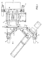
- the slipform paver has, as is apparent from Fig. 1, a chassis 2, which consists of a machine frame 4 extending parallel to the working direction, telescoping from the machine frame 4 side rails 8 and extending transversely to the direction of cross beams 18,20.
- the working direction is indicated in Fig. 1 with an arrow.
- the transverse in the direction of the cross member 18 is rigidly connected to the machine frame 4 and takes in two vertically staggered planes rear cruisers 15, which are telescopically transversely to the direction of the cross member 18.
- a drive unit 3 is connected to the machine frame 4, which provides a hydraulic drive power for the propulsion and for the adjusting devices of the slipform paver.
- the front in the direction of the cross member 20 is rigidly connected to the telescopic side rails 8, which are telescopically out of the machine frame 4 in the working direction to change the distance between the front of the vessels 14 and the rear tractors 15, if necessary, and thus the overall length of the slipform to change.
- the machine frame 4 or the side members 8 need no adjusting device, since the lengthening or shortening of the machine frame can take place solely with the aid of the ships 14,15.
- a safety chain or safety rope between the rear cross member 18 and the front cross member 20 can prevent telescoping the side members 8 too far. If the side members 8 are in the correct position, they are secured in the machine frame 4 by means of bolts.
- a sliding cross-member 22 is arranged, which is parallel to the cross member 20 by means of a piston-cylinder unit 23 slidably.
- the front carriages 14 are articulated at their outer ends by means of a respective parallelogram pivoting device 17.
- the pivoting means 17 with associated piston-cylinder units 13 allow the setting of different gauges between the two front carriages 14, while using the sliding beam 22, the tracking can be varied.
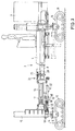
- each cruise ship 14 consists of a lifting column 10 on the orthogonal to the machine frame 4, a chain drive 16 is downwardly extendable.
- the extendable part 9 of the lifting column 10 is surrounded by a steering ring 66 which is actuated by the steering gear 32.
- the steering gear 32 consists of a piston-cylinder unit 60 with a cylinder housing 62 and a piston rod 64 which acts on at least two circularly bent arms 36,40.
- the cylinder housing 62 is mounted on an axis orthogonal to the machine frame 4 extending axis 63 hingedly connected to a lifting column 10 Hubklalenflansch 11.
- the pivot joint 61 is located on the piston rod 64 facing the end of the cylinder housing 62.
- a first hinge 68 is provided which connects the handlebar 40 connected to the steering arm 40, the head of the piston rod 64 and the one end of the arm 36 with each other.
- the handlebar 36 may be provided in a double arrangement, wherein the handlebar 40 is arranged in the joint 68 between the links 36.
- the free end of the link 36 is secured to the Hubchulenflansch 11 with a second relative to the lifting column 10 fixed hinge 72, while the free end of the arm 40 is coupled via a third joint 76 to the steering ring 66.
- the steering gear 32 is moved in a direction orthogonal to the axis of the lifting column 10 extending plane.
- the steering ring 66 has two diametrically opposite sliding blocks 67, which are arranged in a groove on the inner circumference of the steering ring 66, project radially inwards, and engage in corresponding longitudinal grooves 65 of the lower part 9 of the lifting column 10.
- a steering of the track drive 16 is made possible regardless of the height adjustment of the track drive 16.
- the Fign. 4,5a, 5b show different positions of the steering gear 32 and the corresponding adjusted steering angle of the track drive 16th
- FIG. 4 shows the central position when traveling straight ahead parallel to the longitudinal members 8 of the machine frame 4.
- Fig. 5a shows a steering angle of the track drive 16 to the right, the circular curved handlebars 36,40 closely surround the lower part 9 of the lifting column.
- the piston rod 64 is in its retracted position.
- Fig. 5b shows a steering angle to the left, in which the piston rod 64 is in its extended position.
- the Fign. illustrate the extended in relation to normal steering angles of ⁇ 25 ° to 30 ° steering angle.
- the slipform paver is easier to steer and better maneuverable due to the now adjustable in a significantly wider range steering angle due to the possible tight curve radii both when moving the slipform paver and during operation.
Landscapes
- Engineering & Computer Science (AREA)
- Chemical & Material Sciences (AREA)
- Combustion & Propulsion (AREA)
- Transportation (AREA)
- Mechanical Engineering (AREA)
- Civil Engineering (AREA)
- Architecture (AREA)
- Structural Engineering (AREA)
- Road Paving Machines (AREA)
- Lubricants (AREA)
- Harvester Elements (AREA)
- Combines (AREA)
- Formation And Processing Of Food Products (AREA)
- Forms Removed On Construction Sites Or Auxiliary Members Thereof (AREA)
- Soil Working Implements (AREA)
Description
- Die Erfindung betrifft ein Fahrschiff für eine Baumaschine nach dem Oberbegriff des Anspruchs 1, sowie einen Gleitschalungsfertiger nach dem Oberbegriff des Anspruchs 12.
- Gleitschalungsfertiger werden benötigt, um beispielsweise Straßendecken aus Beton oder neben der Fahrbahn, Kanäle, Leitwände oder Wasserrinnen aus Beton herzustellen. Bekannte Gleitschalungsfertiger bestehen aus einem Maschinenrahmen mit einem Fahrgestell und mehreren Fahrschiffen aus lenkbaren Kettenlaufwerken und Hubsäulen besteht. Unterschiedliche Arbeitseinrichtungen zum Verteilen und Glätten oder Formen des Betons können an dem Maschinenrahmen befestigt werden.
- Ein gattungsgemäßer Gleitschalungsfertiger ist beispielsweise aus der US 4 029 165 A oder der DE 198 14 052 A1 bekannt.
- Der Erfindung liegt die Aufgabe zugrunde, ein Fahrschiff für eine Baumaschine, insbesondere für einen Gleitschalungsfertiger der eingangs genannten Art zu schaffen, dessen Manövrierfähigkeit verbessert ist.
- Zur Lösung dieser Aufgabe dienen die Merkmale des Anspruchs 1 bzw. 12.
- Die Erfindung sieht in vorteilhafter Weise vor, dass bei einem Fahrschiff für eine Baumaschine, mit einer Hubsäule für die Höhenverstellung und mit einem Kettenlaufwerk, das mit Hilfe eines Lenkgetriebes lenkbar ist, wobei die Hubsäule einen Hubsäulenflansch aufweist, das Lenkgetriebe zwei gebogene Lenker aufweist, die gelenkig über ein erstes Gelenk miteinander verbunden sind, wobei das freie Ende des ersten Lenkers mit einem zweiten relativ zur Hubsäule ortsfesten Gelenk an den Hubsäulenflansch angekoppelt ist, während das freie Ende des zweiten Lenkers über ein drittes Gelenk an einem Lenkring angekoppelt ist, der mit dem ausfahrbaren Teil der Hubsäule im Eingriff ist.
- Die Baumaschine kann ein Gleitschalungsfertiger sein.
- Zumindest die in Arbeitsrichtung vorderen Fahrschiffe weisen ein Lenkgetriebe zum Verschwenken der Kettenlaufwerke auf, wobei der aus der Mittellage in Arbeitsrichtung einstellbare Lenkwinkel einen Betrag von ± 50° bis 60°, vorzugsweise ± 75° überschreitet.
- Ein solcher Lenkwinkel ermöglicht besonders enge Kurvenradien z.B. wenn beim Offset-Einbau mit einem Gleitschalungsfertiger die Offsetmulde rechts angebaut ist und der Bahnverlauf eine Linkskurve vorsieht. Dann muß der Gleitschalungsfertiger eine besonders enge Innenkurve ausführen.
- Hierzu weist das Lenkgetriebe zwei vorzugsweise kreisförmig gebogene Lenker auf, die in einer Bewegungsebene bewegt werden, die orthogonal zur Achse der Hubsäule verläuft.
- Insbesondere der Krümmungsradius der Lenker ist dem Durchmesser der Hubsäule für das Fahrschiff angepasst, so daß die Lenker in der einen Endposition des Lenkgetriebes die Hubsäule eng umschließen.
- Das Lenkgetriebe weist als Stelleinrichtung eine Kolben-Zylindereinheit mit einem Zylindergehäuse und einer in dem Zylindergehäuse linear beweglichen Kolbenstange auf.
- Jeweils ein Ende der beiden Lenker ist über ein gemeinsames Gelenk an dem freien Ende der Kolbenstange miteinander gekoppelt, während das andere Ende des ersten Lenkers an einem zu dem Fahrschiff ortsfesten zweiten Gelenk und das andere Ende des zweiten Lenkers an einem zu dem Kettenlaufwerk ortsfesten dritten Gelenk angekoppelt sind.
- Das Zylindergehäuse der Kolben-Zylindereinheit ist um eine parallel zur Achse der Hubsäule verlaufende Achse schwenkbar auf an einem zu der Hubsäule bzw. dem Fahrschiff ortsfesten Teil gelagert.
- Im folgenden wird unter Bezugnahme auf die Zeichnungen ein Ausführungsbeispiel der Erfindung näher erläutert:
- Es zeigen:
- Fig. 1
- eine Draufsicht auf einen Gleitschalungsfertiger,
- Fig. 2
- eine Draufsicht gemäß Fig. 1, in der die Einstellbereiche für die Spurlage der Fahrschiffe angegeben sind,
- Fig. 3
- eine Seitenansicht des Gleitschalungsfertigers ohne Fördereinrichtung,
- Fig. 4
- ein Lenkgetriebe für die Kettenlaufwerke, und
- Fign. 5a, 5b
- unterschiedliche Lenkpositionen des Lenkgetriebes.
- Der Gleitschalungsfertiger weist, wie aus Fig. 1 ersichtlich ist, ein Fahrgestell 2 auf, das aus einem Maschinenrahmen 4 mit parallel zur Arbeitsrichtung verlaufenden, aus dem Maschinenrahmen 4 teleskopierbaren Längsträgern 8 und aus quer zur Arbeitsrichtung verlaufenden Querträgern 18,20 besteht. Die Arbeitsrichtung ist in Fig. 1 mit einem Pfeil gekennzeichnet. Der in Arbeitsrichtung hintere Querträger 18 ist mit dem Maschinenrahmen 4 starr verbunden und nimmt in zwei vertikal zueinander versetzten Ebenen hintere Fahrschiffe 15 auf, die quer zur Arbeitsrichtung aus dem Querträger 18 teleskopierbar sind. In Arbeitsrichtung hinter dem Querträger 18 ist eine Antriebseinheit 3 mit dem Maschinenrahmen 4 verbunden, die eine hydraulische Antriebsleistung für den Vortrieb und für die Stelleinrichtungen des Gleitschalungsfertigers liefert.
- Der in Arbeitrichtung vordere Querträger 20 ist mit den teleskopierbaren Längsträgern 8 starr verbunden, die aus dem Maschinenrahmen 4 heraus in Arbeitsrichtung teleskopierbar sind, um bei Bedarf den Abstand zwischen den vorderen Fahrschiffen 14 und den hinteren Fahrschiffen 15 zu verändern und somit die Gesamtlänge des Gleitschalungsfertigers zu verändern. Der Maschinenrahmen 4 bzw. die Längsträger 8 benötigen hierzu keine Stelleinrichtung, da das Verlängern bzw. Verkürzen des Maschinenrahmens allein mit Hilfe der Fahrschiffe 14,15 erfolgen kann. Eine Sicherungskette oder ein Sicherungsseil zwischen dem hinteren Querträger 18 und dem vorderen Querträger 20 kann ein zu weites Teleskopieren der Längsträger 8 verhindern. Befinden sich die Längsträger 8 in der richtigen Position, werden Sie mit Hilfe von Bolzen in dem Maschinenrahmen 4 gesichert.
- An dem in Arbeitsrichtung vorderen Querträger 20 ist eine Schiebetraverse 22 angeordnet, die mit Hilfe einer Kolben-Zylindereinheit 23 parallel zum Querträger 20 verschiebbar ist.
- An der Schiebetraverse 22 sind an ihren äußeren Enden die vorderen Fahrschiffe 14 mit Hilfe jeweils einer parallelogrammartigen Schwenkeinrichtung 17 angelenkt. Die Schwenkeinrichtungen 17 mit zugehörigen Kolben-Zylindereinheiten 13 erlauben die Einstellung unterschiedlicher Spurweiten zwischen den beiden vorderen Fahrschiffen 14, während mit Hilfe der Schiebetraverse 22 die Spurlage variiert werden kann.
- Während die hinteren Fahrschiffe mit einem herkömmlichen Lenkgetriebe versehen sind, weisen die vorderen Fahrschiffe 14 ein Lenkgetriebe 32 auf, das einen Lenkeinschlag aus der Mittellage in Arbeitsrichtung von mehr als ± 75° erlaubt. Jedes Fahrschiff 14 besteht aus einer Hubsäule 10 auf der orthogonal zum Maschinenrahmen 4 ein Kettenlaufwerk 16 nach unten ausfahrbar ist. Der ausfahrbare Teil 9 der Hubsäule 10 wird dabei von einem Lenkring 66 umgeben, der von dem Lenkgetriebe 32 betätigt wird.
- Das Lenkgetriebe 32 besteht aus einer Kolben-Zylindereinheit 60 mit einem Zylindergehäuse 62 und einer Kolbenstange 64, die auf mindestens zwei kreisförmig gebogenen Lenker 36,40 einwirkt. Das Zylindergehäuse 62 ist dabei um eine orthogonal zu dem Maschinenrahmen 4 verlaufende Achse 63 gelenkig an einem mit der Hubsäule 10 verbundenen Hubsäulenflansch 11 gelagert. Das Schwenkgelenk 61 befindet sich dabei an dem der Kolbenstange 64 zugewandten Ende des Zylindergehäuses 62. An dem freien Ende der Kolbenstange 64 ist ein erstes Gelenk 68 vorgesehen, das den mit dem Lenkring 66 verbundenen Lenker 40, den Kopf der Kolbenstange 64 und das eine Ende des Lenkers 36 miteinander gelenkig verbindet. Der Lenker 36 kann in doppelter Anordnung vorgesehen sein, wobei der Lenker 40 in dem Gelenk 68 zwischen den Lenkern 36 angeordnet ist. Das freie Ende der Lenker 36 ist mit einem zweiten relativ zur Hubsäule 10 ortsfesten Gelenk 72 an dem Hubsäulenflansch 11 befestigt, während das freie Ende des Lenkers 40 über ein drittes Gelenk 76 an den Lenkring 66 angekoppelt ist. Das Lenkgetriebe 32 wird in einer orthogonal zur Achse der Hubsäule 10 verlaufenden Ebene bewegt.
- Der Lenkring 66 weist zwei diametral gegenüberliegende Nutensteine 67 auf, die in einer Nut am Innenumfang des Lenkrings 66 angeordnet sind, radial nach innen vorstehen, und in entsprechende Längsnuten 65 des unteren Teils 9 der Hubsäule 10 eingreifen. Damit wird eine Lenkung des Kettenlaufwerks 16 unabhängig von der Höheneinstellung des Kettenlaufwerks 16 ermöglicht.
- Die Fign. 4,5a,5b zeigen unterschiedliche Positionen des Lenkgetriebes 32 und den entsprechend eingestellten Lenkeinschlag des Kettenlaufwerkes 16.
- Fig. 4 zeigt die Mittellage bei Geradeausfahrt parallel zu den Längsträgern 8 des Maschinenrahmens 4.
- Fig. 5a zeigt einen Lenkeinschlag des Kettenlaufwerks 16 nach rechts, wobei die kreisförmig gebogenen Lenker 36,40 den unteren Teil 9 der Hubsäule eng umschließen. Die Kolbenstange 64 befindet sich dabei in ihrer eingefahrenen Position.
- Fig. 5b zeigt einen Lenkeinschlag nach links, in der sich die Kolbenstange 64 in ihrer ausgefahrenen Position befindet. Die Fign. verdeutlichen den in Relation zu üblichen Lenkeinschlägen von ± 25° bis 30° erweiterten Lenkeinschlagswinkel. Der Gleitschalungsfertiger ist aufgrund der nunmehr in einem erheblich weiteren Bereich einstellbaren Lenkwinkel einfacher zu lenken und besser manövrierfähig aufgrund der möglichen engen Kurvenradien sowohl beim Umsetzen des Gleitschalungsfertigers als auch im Betrieb.
Claims (12)
- Fahrschiff für eine Baumaschine, mit einer Hubsäule (10) für die Höhenverstellung, mit einem Lenkgetriebe (32) und mit einem Kettenlaufwerk (16), das mit Hilfe des Lenkgetriebes (32) lenkbar ist, wobei die Hubsäule (10) einen Hubsäulenflansch (11) aufweist,
dadurch gekennzeichnet,
dass das Lenkgetriebe (32) zwei gebogene Lenker (36,40) aufweist, die gelenkig über ein erstes Gelenk (68) miteinander verbunden sind, wobei das freie Ende des ersten Lenkers (36) mit einem zweiten relativ zur Hubsäule (10) ortsfesten Gelenk (72) an den Hubsäulenflansch (11) angekoppelt ist, während das freie Ende des zweiten Lenkers (40) über ein drittes Gelenk (76) an einem Lenkring (66) angekoppelt ist, der mit dem ausfahrbaren Teil (9) der Hubsäule (10) im Eingriff ist. - Fahrschiff nach Anspruch 1, dadurch gekennzeichnet, dass der aus der Mittellage einstellbare Lenkwinkel des Lenkgetriebes (32) einen Betrag von ± 50° bis 60°, vorzugsweise ± 75°, überschreitet.
- Fahrschiff nach Anspruch 1 oder 2, dadurch gekennzeichnet, dass die Bewegungsebene der Lenker (36,40) orthogonal zur Achse der Hubsäule (10) verläuft.
- Fahrschiff nach einem der Ansprüche 1 bis 3, dadurch gekennzeichnet, dass der Krümmungsradius der Lenker (36,40) dem Durchmesser der Hubsäule (10) für das Fahrschiff (14) angepasst ist.
- Fahrschiff nach einem der Ansprüche 1 bis 4, dadurch gekennzeichnet, dass das Lenkgetriebe (32) als Stelleinrichtung eine Kolben-Zylindereinheit (60) mit einem Zylindergehäuse (62) und einer in dem Zylindergehäuse (62) linear beweglichen Kolbenstange (64) aufweist.
- Fahrschiff nach Anspruch 5, dadurch gekennzeichnet, dass jeweils ein Ende der beiden Lenker (36,40) über das gemeinsame erste Gelenk (68) an dem freien Ende der Kolbenstange (64) miteinander gekoppelt sind.
- Fahrschiff nach Anspruch 5 oder 6, dadurch gekennzeichnet, dass das Zylindergehäuse (62) der Kolben-Zylindereinheit (60) schwenkbar um eine, in eingebauten Zustand des Fahrschiffes, orthogonal zur Ebene des Baumaschinenrahmens (4) verlaufende Achse (63) an einem Teil (11) der Hubsäule (10) gelagert ist.
- Fahrschiff nach einem der Ansprüche 5 bis 7, dadurch gekennzeichnet, dass die Kolben-Zylindereinheit (60) schwenkbar an dem Hubsäulenflansch (11) gelagert ist.
- Fahrschiff nach einem der Ansprüche 1 bis 7, dadurch gekennzeichnet, dass der Lenkring (66) über Nutensteine (67), die in Längsnuten (65) des ausfahrbaren Teils (9) der Hubsäule (10) eingreifen, unabhängig von der Höheneinstellung des Kettenlaufwerks (16) mit der Hubsäule (10) im Eingriff ist.
- Fahrschiff nach einem der Ansprüche 1 bis 9, dadurch gekennzeichnet, dass das Fahrschiff (14) über eine Schwenkeinrichtung (17) an der Baumaschine anlenkbar ist.
- Fahrschiff nach Anspruch 10, dadurch gekenneichnet, dass die Schwenkeinrichtung (17) aus parallelogrammartig angeordneten Lenkern besteht, die von einer Kolben-Zylindereinheit (13) antreibbar sind.
- Gleitschalungsfertiger mit einem Maschinenrahmen (4) mit parallel zur Arbeitsrichtung verlaufenden Längsträgern (8) sowie mit Querträgern (18,20) und mit inem Fahrgestell (2) bestehend aus mehreren mit einer Hubsäule (10) höhenverstellbaren Fahrschiffen (14,15) mit lenkbaren Kettenlaufwerken (16), die die Ebene des Maschinenrahmens (4) in einer vorgegebenen Lage halten, gekennzeichnet durch Fahrschiffe (14,15) nach einem der Ansprüche 1 bis 11.
Applications Claiming Priority (3)
| Application Number | Priority Date | Filing Date | Title |
|---|---|---|---|
| DE19957048A DE19957048C1 (de) | 1999-11-26 | 1999-11-26 | Gleitschalungsfertiger |
| DE19957048 | 1999-11-26 | ||
| EP00125724A EP1103659B1 (de) | 1999-11-26 | 2000-11-24 | Gleitschalungsfertiger |
Related Parent Applications (1)
| Application Number | Title | Priority Date | Filing Date |
|---|---|---|---|
| EP00125724A Division EP1103659B1 (de) | 1999-11-26 | 2000-11-24 | Gleitschalungsfertiger |
Publications (2)
| Publication Number | Publication Date |
|---|---|
| EP1522632A1 EP1522632A1 (de) | 2005-04-13 |
| EP1522632B1 true EP1522632B1 (de) | 2006-03-08 |
Family
ID=7930490
Family Applications (2)
| Application Number | Title | Priority Date | Filing Date |
|---|---|---|---|
| EP00125724A Expired - Lifetime EP1103659B1 (de) | 1999-11-26 | 2000-11-24 | Gleitschalungsfertiger |
| EP04105768A Expired - Lifetime EP1522632B1 (de) | 1999-11-26 | 2000-11-24 | Fahrschiff für eine Baumaschine, sowie Gleitschalungsfertiger mit einem solchen Fahrschiff |
Family Applications Before (1)
| Application Number | Title | Priority Date | Filing Date |
|---|---|---|---|
| EP00125724A Expired - Lifetime EP1103659B1 (de) | 1999-11-26 | 2000-11-24 | Gleitschalungsfertiger |
Country Status (6)
| Country | Link |
|---|---|
| US (1) | US6481924B1 (de) |
| EP (2) | EP1103659B1 (de) |
| AT (2) | ATE393265T1 (de) |
| DE (3) | DE19957048C1 (de) |
| ES (1) | ES2304339T3 (de) |
| PT (1) | PT1103659E (de) |
Cited By (1)
| Publication number | Priority date | Publication date | Assignee | Title |
|---|---|---|---|---|
| EP2514875A1 (de) | 2011-04-19 | 2012-10-24 | Wirtgen GmbH | Rangiervorrichtung zur Montage einer auswechselbaren Fräseinrichtung einer Strassenbaumaschine |
Families Citing this family (54)
| Publication number | Priority date | Publication date | Assignee | Title |
|---|---|---|---|---|
| DE10128564B4 (de) * | 2001-06-13 | 2005-10-27 | Wirtgen Gmbh | Gleitschalungsfertiger |
| US6692185B2 (en) * | 2001-10-17 | 2004-02-17 | Power Curbers, Inc. | Adjusting arrangement for steerable transport assembly for self-propelled construction vehicle |
| CA2418545A1 (en) * | 2002-02-06 | 2003-08-06 | N. Piccoli Construction | Device for forming tight radius curbs and gutters with a paving machine |
| DE10210763A1 (de) * | 2002-03-12 | 2003-10-02 | Metso Dynapac Gmbh | Straßendeckenfräse |
| DE10358363B4 (de) * | 2003-10-15 | 2007-10-31 | Wieberneit, Christian | Gleitschalungsfertiger zum Fertigen von Oberflächenbelägen |
| BE1015798A3 (nl) * | 2003-11-24 | 2005-09-06 | Cmi Belgium Nv | Betonneermachine. |
| ITTO20040499A1 (it) | 2004-07-15 | 2004-10-15 | Bitelli Spa | Macchina operatrice in particolare scarificatrice stradale |
| DE102005003739B3 (de) * | 2005-01-26 | 2006-11-16 | Wirtgen Gmbh | Baumaschine, sowie Schwenkeinrichtung |
| US8073566B2 (en) | 2007-04-05 | 2011-12-06 | Power Curbers, Inc. | Automated stringline installation system |
| US8312957B1 (en) * | 2008-07-08 | 2012-11-20 | Stoltzfus Daniel R | Apparatus for moving concrete pump hoses |
| US7950478B2 (en) * | 2008-11-21 | 2011-05-31 | Intelliport Corporation | Heavy capacity transporter having multiple track-axles |
| DE102009040079A1 (de) * | 2009-09-04 | 2011-03-10 | Wirtgen Gmbh | Gleitschalungsfertiger |
| DE102009059106A1 (de) | 2009-12-18 | 2011-06-22 | Wirtgen GmbH, 53578 | Selbstfahrende Baumaschine und Verfahren zur Steuerung einer selbstfahrenden Baumaschine |
| US8118518B2 (en) * | 2010-02-09 | 2012-02-21 | Guntert & Zimmerman Const. Div., Inc. | Slipform paving machine with adjustable length tractor frame |
| US9908571B2 (en) | 2010-03-26 | 2018-03-06 | Guntert & Zimmerman Const. Div., Inc. | Adjustable bolster swing legs for slipform paving machines |
| PL2377997T3 (pl) * | 2010-04-16 | 2015-01-30 | Joseph Voegele Ag | Pojazd załadowczy |
| DE102011102704A1 (de) * | 2011-05-20 | 2012-11-22 | Bilfinger Berger Ingenieurbau Gmbh | Fertiger |
| DE102012001289A1 (de) | 2012-01-25 | 2013-07-25 | Wirtgen Gmbh | Selbstfahrende Baumaschine und Verfahren zum Steuern einer selbstfahrenden Baumaschine |
| US8989968B2 (en) * | 2012-10-12 | 2015-03-24 | Wirtgen Gmbh | Self-propelled civil engineering machine system with field rover |
| US9096977B2 (en) | 2013-05-23 | 2015-08-04 | Wirtgen Gmbh | Milling machine with location indicator system |
| US9242410B2 (en) * | 2013-09-17 | 2016-01-26 | Mcelroy Manufacturing, Inc. | Top-loading straddle-mounted pipe fusion machine |
| US9297171B1 (en) * | 2014-01-17 | 2016-03-29 | Peter A. Ligman | Track drive apparatus for screeding concrete |
| US9663162B1 (en) * | 2014-02-28 | 2017-05-30 | Gomaco Corporation | Hydraulic pivot arm positioning assembly |
| US9909267B1 (en) | 2014-03-05 | 2018-03-06 | Ligchine International Corporation | Paver head assembly |
| DE102014005077A1 (de) | 2014-04-04 | 2015-10-08 | Wirtgen Gmbh | Selbstfahrende Baumaschine und Verfahren zum Steuern einer selbstfahrenden Baumaschine |
| US9764762B2 (en) * | 2014-05-13 | 2017-09-19 | Gomaco Corporation | Rotary pivot arm positioning assembly |
| DE102014012825A1 (de) | 2014-08-28 | 2016-03-03 | Wirtgen Gmbh | Selbstfahrende Baumaschine und Verfahren zur Steuerung einer selbstfahrenden Baumaschine |
| DE102014012836B4 (de) | 2014-08-28 | 2018-09-13 | Wirtgen Gmbh | Selbstfahrende Baumaschine und Verfahren zur Visualisierung des Bearbeitungsumfeldes einer sich im Gelände bewegenden Baumaschine |
| DE102014012831B4 (de) | 2014-08-28 | 2018-10-04 | Wirtgen Gmbh | Selbstfahrende Baumaschine und Verfahren zum Steuern einer selbstfahrenden Baumaschine |
| US12123152B2 (en) | 2015-10-23 | 2024-10-22 | Ligchine International Corporation | Side-step concrete screeding apparatus |
| US10233658B1 (en) | 2016-10-14 | 2019-03-19 | Ligchine International Corporation | Multi-rotational concrete screed apparatus for screeding concrete |
| CN107558338A (zh) * | 2017-10-17 | 2018-01-09 | 江苏四明工程机械有限公司 | 滑模摊铺机履带转向装置 |
| DE102017010425A1 (de) | 2017-11-12 | 2019-05-16 | Wirtgen Gmbh | Selbstfahrende Baumaschine und Verfahren zum Steuern einer selbstfahrenden Baumaschine |
| DE102017012010A1 (de) | 2017-12-22 | 2019-06-27 | Wirtgen Gmbh | Selbstfahrende Baumaschine und Verfahren zum Steuern einer selbstfahrenden Baumaschine |
| DE102018105536A1 (de) * | 2018-03-09 | 2019-09-12 | Wirtgen Gmbh | Gleitschalungsfertiger und Verfahren zum Betreiben eines Gleitschalungsfertigers |
| DE102018119962A1 (de) | 2018-08-16 | 2020-02-20 | Wirtgen Gmbh | Selbstfahrende Baumaschine und Verfahren zum Steuern einer selbstfahrenden Baumaschine |
| US11560727B2 (en) | 2018-10-08 | 2023-01-24 | Ligchine International Corporation | Apparatus for screeding concrete |
| US11162232B2 (en) | 2018-10-08 | 2021-11-02 | Ligchine International Corporation | Drive system for screeding concrete |
| DE102019118059A1 (de) * | 2019-07-04 | 2021-01-07 | Wirtgen Gmbh | Selbstfahrende Baumaschine und Verfahren zum Steuern einer selbstfahrenden Baumaschine |
| DE102019125590A1 (de) * | 2019-09-24 | 2021-03-25 | Wirtgen Gmbh | Überwachungsvorrichtung für einen Gleitschalungsfertiger zur Überwachung der Verdichtung von Beton und Verfahren zur Überwachung der Verdichtung von Beton während des Betriebs eines Gleitschalungsfertigers |
| CN110593061B (zh) * | 2019-10-10 | 2024-06-11 | 江苏四明工程机械有限公司 | 智能回转式履带转向立柱及滑模摊铺机 |
| CN111648306A (zh) * | 2020-07-20 | 2020-09-11 | 河南水建集团有限公司 | 一种渠道衬砌用混凝土摊铺装置 |
| CN111996879A (zh) * | 2020-09-15 | 2020-11-27 | 周建刚 | 一种滑模机模具连接调节机构 |
| AU2022226628A1 (en) | 2021-02-23 | 2023-08-31 | Ligchine International Corporation | Swing boom concrete screeding apparatus |
| CN112873505A (zh) * | 2021-03-30 | 2021-06-01 | 中铁第四勘察设计院集团有限公司 | 轨道梁预制装置 |
| US12173456B2 (en) | 2021-06-02 | 2024-12-24 | Gomaco Corporation | Leg assembly for construction machine |
| US11254359B1 (en) | 2021-06-02 | 2022-02-22 | Gomaco Corporation | Leg assembly for construction machine |
| WO2023076906A1 (en) | 2021-10-25 | 2023-05-04 | Ligchine International Corporation | Portable telescopic conveyor belt |
| CN114990967B (zh) * | 2022-07-04 | 2024-05-31 | 江苏四明工程机械有限公司 | 一种升降立柱回转装置及滑模摊铺机 |
| DE102023109836A1 (de) | 2023-04-19 | 2024-10-24 | Wirtgen Gmbh | Gleitschalungsfertiger |
| DE102023114147A1 (de) | 2023-05-30 | 2024-12-05 | Wirtgen Gmbh | Gleitschalungsfertiger |
| DE102023123252A1 (de) | 2023-08-29 | 2025-03-06 | Wirtgen Gmbh | Überwachungsvorrichtung für einen Gleitschalungsfertiger zur Überwachung der Verdichtung von Beton und Verfahren zur Überwachung der Verdichtung von Beton während des Betriebs eines Gleitschalungsfertigers |
| DE102024102291A1 (de) | 2024-01-26 | 2025-07-31 | Wirtgen Gmbh | Gleitschalungsfertiger |
| DE102024115136A1 (de) | 2024-05-29 | 2025-12-04 | Wirtgen Gmbh | Gleitschalungsfertiger |
Family Cites Families (20)
| Publication number | Priority date | Publication date | Assignee | Title |
|---|---|---|---|---|
| GB942349A (en) * | 1961-09-01 | 1963-11-20 | Renner Co | Improvements in or relating to curb forming machines |
| US3392797A (en) * | 1964-08-27 | 1968-07-16 | Raymond Corp | Steering and suspension systems for motorized lift trucks |
| US3330188A (en) * | 1964-12-31 | 1967-07-11 | Layton Mfg Co | Road widener |
| US3540359A (en) * | 1968-08-02 | 1970-11-17 | Cmi Corp | Paving material distribution apparatus |
| US3710695A (en) * | 1971-01-04 | 1973-01-16 | Miller Formless Co Inc | Construction machine and controls therefor |
| US3970405A (en) * | 1974-05-03 | 1976-07-20 | Cmi Corporation | Slipform paving apparatus |
| US4029165A (en) * | 1976-02-05 | 1977-06-14 | Miller Formless Co., Inc. | Convertible construction machine |
| US4120507A (en) * | 1977-03-16 | 1978-10-17 | Miller Formless Co. Inc. | Compensated extendable steering means for heavy machines |
| US4197032A (en) * | 1978-08-02 | 1980-04-08 | Power Curbers, Inc. | Apparatus and method for forming a continuous strip of paving |
| US4493586A (en) * | 1982-02-16 | 1985-01-15 | Morrison-Knudsen Co., Inc. | Rip-rap laying machine and method of laying rip-rap |
| US4778305A (en) * | 1987-03-27 | 1988-10-18 | Rexworks Inc. | Slip-form paver with laterally moveable paving tool |
| US4789266A (en) * | 1987-11-27 | 1988-12-06 | Power Curbers, Inc. | Self-propelled construction apparatus |
| US5127335A (en) * | 1990-07-09 | 1992-07-07 | Kershaw Manufacturing Company, Inc. | Points and crossing changer |
| US5590977A (en) * | 1995-05-25 | 1997-01-07 | Guntert & Zimmerman Constr. Div. Inc. | Four track paving machine and process of transport |
| US5615972A (en) * | 1995-07-20 | 1997-04-01 | Guntert & Zimmerman Construction Div., Inc. | Paving machine with extended telescoping members |
| US5647688A (en) * | 1995-07-20 | 1997-07-15 | Guntert & Zimmerman Const. Div., Inc. | Paving machine with extended telescoping members |
| DE19631042C5 (de) * | 1996-08-01 | 2015-08-20 | Wirtgen Gmbh | Straßenbaumaschinen zum Bearbeiten von Fahrbahnen |
| BE1011289A3 (nl) * | 1997-07-23 | 1999-07-06 | Casters Francois | Betonneermachine. |
| DE19814052A1 (de) * | 1998-03-30 | 1999-10-14 | Wirtgen Gmbh | Gleitschalungsfertiger |
| IT1308143B1 (it) * | 1999-03-23 | 2001-11-29 | Bitelli Spa | Macchina operatrice per la lavorazione di suoli con ruote posterioririentranti e sterzanti. |
-
1999
- 1999-11-26 DE DE19957048A patent/DE19957048C1/de not_active Expired - Fee Related
-
2000
- 2000-11-21 US US09/716,364 patent/US6481924B1/en not_active Expired - Lifetime
- 2000-11-24 PT PT00125724T patent/PT1103659E/pt unknown
- 2000-11-24 DE DE50012386T patent/DE50012386D1/de not_active Expired - Lifetime
- 2000-11-24 ES ES00125724T patent/ES2304339T3/es not_active Expired - Lifetime
- 2000-11-24 EP EP00125724A patent/EP1103659B1/de not_active Expired - Lifetime
- 2000-11-24 AT AT00125724T patent/ATE393265T1/de active
- 2000-11-24 AT AT04105768T patent/ATE319882T1/de not_active IP Right Cessation
- 2000-11-24 EP EP04105768A patent/EP1522632B1/de not_active Expired - Lifetime
- 2000-11-24 DE DE50015122T patent/DE50015122D1/de not_active Expired - Lifetime
Cited By (3)
| Publication number | Priority date | Publication date | Assignee | Title |
|---|---|---|---|---|
| EP2514875A1 (de) | 2011-04-19 | 2012-10-24 | Wirtgen GmbH | Rangiervorrichtung zur Montage einer auswechselbaren Fräseinrichtung einer Strassenbaumaschine |
| DE102011018222A1 (de) | 2011-04-19 | 2012-10-25 | Wirtgen Gmbh | Rangiervorrichtung zur Montage einer auswechselbaren Fräseinrichtung einer Straßenbaumaschine |
| DE102011018222B4 (de) * | 2011-04-19 | 2015-05-28 | Wirtgen Gmbh | Rangiervorrichtung zur Montage einer auswechselbaren Fräseinrichtung einer Straßenbaumaschine |
Also Published As
| Publication number | Publication date |
|---|---|
| PT1103659E (pt) | 2008-07-07 |
| DE50012386D1 (de) | 2006-05-04 |
| EP1522632A1 (de) | 2005-04-13 |
| DE19957048C1 (de) | 2001-08-09 |
| EP1103659B1 (de) | 2008-04-23 |
| US6481924B1 (en) | 2002-11-19 |
| ATE393265T1 (de) | 2008-05-15 |
| ATE319882T1 (de) | 2006-03-15 |
| DE50015122D1 (de) | 2008-06-05 |
| EP1103659A3 (de) | 2003-08-13 |
| EP1103659A2 (de) | 2001-05-30 |
| ES2304339T3 (es) | 2008-10-16 |
Similar Documents
| Publication | Publication Date | Title |
|---|---|---|
| EP1522632B1 (de) | Fahrschiff für eine Baumaschine, sowie Gleitschalungsfertiger mit einem solchen Fahrschiff | |
| DE69503858T2 (de) | Teleskopische Radachse mit ausziehbarer Lenkstange | |
| DE1944214C3 (de) | Schienenlos verfahrbarer Dreh kranunterwagen | |
| DE2345412C2 (de) | Zweiachsige Straßenwalze | |
| DE2701868C3 (de) | Fahrbare Grubenausbaueinheit | |
| WO2014090407A1 (de) | Transportfahrzeug mit variabler breite und spurweite und mindestens einer lenkachse | |
| DE102012024247B4 (de) | Transportfahrzeug mit variabler Breite und Spurweite und mindestens einer Lenkachse | |
| DE102014009036B4 (de) | Transportfahrzeug, insbesondere selbstangetriebenes Transportfahrzeug, mit variabler Breite | |
| EP3160828B1 (de) | Transportfahrzeug, insbesondere ein selbstangetriebenes transportfahrzeug, mit variabler breite | |
| DE102005003739B3 (de) | Baumaschine, sowie Schwenkeinrichtung | |
| DE202014005055U1 (de) | Transportfahrzeug, insbesondere selbstangetriebenes Transportfahrzeug, mit variabler Breite | |
| DE1932815C3 (de) | Geländegängiges zweiachsiges Fahrzeug mit Zwei- oder Vierradantrieb | |
| DE2362841B2 (de) | Walzenzug zum Verdichten des Baugrundes o.dgl | |
| DE3405259C2 (de) | Straßentieflader, insbesondere Tiefladeranhänger für Sattelzugmaschinen | |
| EP0518208B1 (de) | Vorrichtung zur Lenkungsumschaltung bei einem Fahrzeugkran | |
| DE4137382C1 (en) | Utility site-work vehicle - is articulated with fixed wheels on front carriage and steering wheels on rear carriage. | |
| DE2164623A1 (de) | Gerät zur Entfernung einer Ofenzustellung | |
| DE10026612A1 (de) | Schalungswagen sowie Schalung mit einem solchen Schalungswagen | |
| DE102004059881A1 (de) | Schwenkbare Stützeinrichtung für eine Straßenbaumaschine, sowie Straßenbaumaschine | |
| DE3940798C2 (de) | ||
| DE3738751C2 (de) | Fahrbare Gleisstopf-, Hebe- und Richtmaschine für den Weichen- und Kreuzungsbereich | |
| DE2557980C2 (de) | Seitenführung für einen mittig unterteilten Schneeräumvorbau an einem Schienenfahrzeug | |
| DE1105444B (de) | Einrichtung zum Einstellen eines gewuenschten Winkels zwischen zwei miteinander schwenkbar verbundenen Bauteilen, insbesondere zwischen Brueckenfahr-bahnteilen | |
| DE3137580C2 (de) | Lenkvorrichtung für ein Raupenfahrzeug | |
| EP2711211B1 (de) | Radaufhängung für ein Schwerlast-Transportfahrzeug sowie ein eine derartige Radaufhäungung verwendendes Schwerlast-Transportfahrzeug |
Legal Events
| Date | Code | Title | Description |
|---|---|---|---|
| PUAI | Public reference made under article 153(3) epc to a published international application that has entered the european phase |
Free format text: ORIGINAL CODE: 0009012 |
|
| AC | Divisional application: reference to earlier application |
Ref document number: 1103659 Country of ref document: EP Kind code of ref document: P |
|
| AK | Designated contracting states |
Kind code of ref document: A1 Designated state(s): AT BE CH CY DE DK ES FI FR GB GR IE IT LI LU MC NL PT SE TR |
|
| 17P | Request for examination filed |
Effective date: 20050315 |
|
| GRAP | Despatch of communication of intention to grant a patent |
Free format text: ORIGINAL CODE: EPIDOSNIGR1 |
|
| AKX | Designation fees paid |
Designated state(s): AT BE CH CY DE DK ES FI FR GB GR IE IT LI LU MC NL PT SE TR |
|
| GRAS | Grant fee paid |
Free format text: ORIGINAL CODE: EPIDOSNIGR3 |
|
| GRAA | (expected) grant |
Free format text: ORIGINAL CODE: 0009210 |
|
| AC | Divisional application: reference to earlier application |
Ref document number: 1103659 Country of ref document: EP Kind code of ref document: P |
|
| AK | Designated contracting states |
Kind code of ref document: B1 Designated state(s): AT BE CH CY DE DK ES FI FR GB GR IE IT LI LU MC NL PT SE TR |
|
| PG25 | Lapsed in a contracting state [announced via postgrant information from national office to epo] |
Ref country code: IT Free format text: LAPSE BECAUSE OF FAILURE TO SUBMIT A TRANSLATION OF THE DESCRIPTION OR TO PAY THE FEE WITHIN THE PRESCRIBED TIME-LIMIT;WARNING: LAPSES OF ITALIAN PATENTS WITH EFFECTIVE DATE BEFORE 2007 MAY HAVE OCCURRED AT ANY TIME BEFORE 2007. THE CORRECT EFFECTIVE DATE MAY BE DIFFERENT FROM THE ONE RECORDED. Effective date: 20060308 Ref country code: IE Free format text: LAPSE BECAUSE OF FAILURE TO SUBMIT A TRANSLATION OF THE DESCRIPTION OR TO PAY THE FEE WITHIN THE PRESCRIBED TIME-LIMIT Effective date: 20060308 |
|
| REG | Reference to a national code |
Ref country code: GB Ref legal event code: FG4D Free format text: NOT ENGLISH |
|
| REG | Reference to a national code |
Ref country code: CH Ref legal event code: EP |
|
| REG | Reference to a national code |
Ref country code: IE Ref legal event code: FG4D Free format text: LANGUAGE OF EP DOCUMENT: GERMAN |
|
| REF | Corresponds to: |
Ref document number: 50012386 Country of ref document: DE Date of ref document: 20060504 Kind code of ref document: P |
|
| PG25 | Lapsed in a contracting state [announced via postgrant information from national office to epo] |
Ref country code: SE Free format text: LAPSE BECAUSE OF FAILURE TO SUBMIT A TRANSLATION OF THE DESCRIPTION OR TO PAY THE FEE WITHIN THE PRESCRIBED TIME-LIMIT Effective date: 20060608 Ref country code: DK Free format text: LAPSE BECAUSE OF FAILURE TO SUBMIT A TRANSLATION OF THE DESCRIPTION OR TO PAY THE FEE WITHIN THE PRESCRIBED TIME-LIMIT Effective date: 20060608 |
|
| PG25 | Lapsed in a contracting state [announced via postgrant information from national office to epo] |
Ref country code: ES Free format text: LAPSE BECAUSE OF FAILURE TO SUBMIT A TRANSLATION OF THE DESCRIPTION OR TO PAY THE FEE WITHIN THE PRESCRIBED TIME-LIMIT Effective date: 20060619 |
|
| GBT | Gb: translation of ep patent filed (gb section 77(6)(a)/1977) |
Effective date: 20060703 |
|
| PG25 | Lapsed in a contracting state [announced via postgrant information from national office to epo] |
Ref country code: PT Free format text: LAPSE BECAUSE OF FAILURE TO SUBMIT A TRANSLATION OF THE DESCRIPTION OR TO PAY THE FEE WITHIN THE PRESCRIBED TIME-LIMIT Effective date: 20060808 |
|
| ET | Fr: translation filed | ||
| REG | Reference to a national code |
Ref country code: IE Ref legal event code: FD4D |
|
| PG25 | Lapsed in a contracting state [announced via postgrant information from national office to epo] |
Ref country code: MC Free format text: LAPSE BECAUSE OF NON-PAYMENT OF DUE FEES Effective date: 20061130 Ref country code: LI Free format text: LAPSE BECAUSE OF NON-PAYMENT OF DUE FEES Effective date: 20061130 Ref country code: CH Free format text: LAPSE BECAUSE OF NON-PAYMENT OF DUE FEES Effective date: 20061130 |
|
| PLBE | No opposition filed within time limit |
Free format text: ORIGINAL CODE: 0009261 |
|
| STAA | Information on the status of an ep patent application or granted ep patent |
Free format text: STATUS: NO OPPOSITION FILED WITHIN TIME LIMIT |
|
| 26N | No opposition filed |
Effective date: 20061211 |
|
| REG | Reference to a national code |
Ref country code: CH Ref legal event code: PL |
|
| PG25 | Lapsed in a contracting state [announced via postgrant information from national office to epo] |
Ref country code: AT Free format text: LAPSE BECAUSE OF NON-PAYMENT OF DUE FEES Effective date: 20061124 |
|
| PG25 | Lapsed in a contracting state [announced via postgrant information from national office to epo] |
Ref country code: GR Free format text: LAPSE BECAUSE OF FAILURE TO SUBMIT A TRANSLATION OF THE DESCRIPTION OR TO PAY THE FEE WITHIN THE PRESCRIBED TIME-LIMIT Effective date: 20060609 |
|
| PG25 | Lapsed in a contracting state [announced via postgrant information from national office to epo] |
Ref country code: FI Free format text: LAPSE BECAUSE OF FAILURE TO SUBMIT A TRANSLATION OF THE DESCRIPTION OR TO PAY THE FEE WITHIN THE PRESCRIBED TIME-LIMIT Effective date: 20060308 |
|
| PG25 | Lapsed in a contracting state [announced via postgrant information from national office to epo] |
Ref country code: LU Free format text: LAPSE BECAUSE OF NON-PAYMENT OF DUE FEES Effective date: 20061124 Ref country code: TR Free format text: LAPSE BECAUSE OF FAILURE TO SUBMIT A TRANSLATION OF THE DESCRIPTION OR TO PAY THE FEE WITHIN THE PRESCRIBED TIME-LIMIT Effective date: 20060308 |
|
| PG25 | Lapsed in a contracting state [announced via postgrant information from national office to epo] |
Ref country code: CY Free format text: LAPSE BECAUSE OF FAILURE TO SUBMIT A TRANSLATION OF THE DESCRIPTION OR TO PAY THE FEE WITHIN THE PRESCRIBED TIME-LIMIT Effective date: 20060308 |
|
| REG | Reference to a national code |
Ref country code: FR Ref legal event code: PLFP Year of fee payment: 16 |
|
| REG | Reference to a national code |
Ref country code: FR Ref legal event code: PLFP Year of fee payment: 17 |
|
| REG | Reference to a national code |
Ref country code: FR Ref legal event code: PLFP Year of fee payment: 18 |
|
| PGFP | Annual fee paid to national office [announced via postgrant information from national office to epo] |
Ref country code: NL Payment date: 20181122 Year of fee payment: 19 |
|
| PGFP | Annual fee paid to national office [announced via postgrant information from national office to epo] |
Ref country code: DE Payment date: 20181204 Year of fee payment: 19 |
|
| PGFP | Annual fee paid to national office [announced via postgrant information from national office to epo] |
Ref country code: IT Payment date: 20181122 Year of fee payment: 19 Ref country code: BE Payment date: 20181122 Year of fee payment: 19 Ref country code: GB Payment date: 20181126 Year of fee payment: 19 Ref country code: FR Payment date: 20181127 Year of fee payment: 19 |
|
| REG | Reference to a national code |
Ref country code: DE Ref legal event code: R119 Ref document number: 50012386 Country of ref document: DE |
|
| REG | Reference to a national code |
Ref country code: NL Ref legal event code: MM Effective date: 20191201 |
|
| REG | Reference to a national code |
Ref country code: BE Ref legal event code: MM Effective date: 20191130 |
|
| GBPC | Gb: european patent ceased through non-payment of renewal fee |
Effective date: 20191124 |
|
| PG25 | Lapsed in a contracting state [announced via postgrant information from national office to epo] |
Ref country code: NL Free format text: LAPSE BECAUSE OF NON-PAYMENT OF DUE FEES Effective date: 20191201 |
|
| PG25 | Lapsed in a contracting state [announced via postgrant information from national office to epo] |
Ref country code: IT Free format text: LAPSE BECAUSE OF NON-PAYMENT OF DUE FEES Effective date: 20191124 Ref country code: DE Free format text: LAPSE BECAUSE OF NON-PAYMENT OF DUE FEES Effective date: 20200603 Ref country code: FR Free format text: LAPSE BECAUSE OF NON-PAYMENT OF DUE FEES Effective date: 20191130 Ref country code: GB Free format text: LAPSE BECAUSE OF NON-PAYMENT OF DUE FEES Effective date: 20191124 |
|
| PG25 | Lapsed in a contracting state [announced via postgrant information from national office to epo] |
Ref country code: BE Free format text: LAPSE BECAUSE OF NON-PAYMENT OF DUE FEES Effective date: 20191130 |