EP1522510A1 - Anordnung zum Verladen von Fahrzeugkarossen - Google Patents
Anordnung zum Verladen von Fahrzeugkarossen Download PDFInfo
- Publication number
- EP1522510A1 EP1522510A1 EP04016709A EP04016709A EP1522510A1 EP 1522510 A1 EP1522510 A1 EP 1522510A1 EP 04016709 A EP04016709 A EP 04016709A EP 04016709 A EP04016709 A EP 04016709A EP 1522510 A1 EP1522510 A1 EP 1522510A1
- Authority
- EP
- European Patent Office
- Prior art keywords
- loading
- bodies
- wagon
- arrangement according
- arrangement
- Prior art date
- Legal status (The legal status is an assumption and is not a legal conclusion. Google has not performed a legal analysis and makes no representation as to the accuracy of the status listed.)
- Granted
Links
Images


Classifications
-
- B—PERFORMING OPERATIONS; TRANSPORTING
- B65—CONVEYING; PACKING; STORING; HANDLING THIN OR FILAMENTARY MATERIAL
- B65G—TRANSPORT OR STORAGE DEVICES, e.g. CONVEYORS FOR LOADING OR TIPPING, SHOP CONVEYOR SYSTEMS OR PNEUMATIC TUBE CONVEYORS
- B65G63/00—Transferring or trans-shipping at storage areas, railway yards or harbours or in opening mining cuts; Marshalling yard installations
- B65G63/02—Transferring or trans-shipping at storage areas, railway yards or harbours or in opening mining cuts; Marshalling yard installations with essentially horizontal transit otherwise than by bridge
- B65G63/022—Transferring or trans-shipping at storage areas, railway yards or harbours or in opening mining cuts; Marshalling yard installations with essentially horizontal transit otherwise than by bridge for articles
- B65G63/025—Transferring or trans-shipping at storage areas, railway yards or harbours or in opening mining cuts; Marshalling yard installations with essentially horizontal transit otherwise than by bridge for articles for containers
-
- Y—GENERAL TAGGING OF NEW TECHNOLOGICAL DEVELOPMENTS; GENERAL TAGGING OF CROSS-SECTIONAL TECHNOLOGIES SPANNING OVER SEVERAL SECTIONS OF THE IPC; TECHNICAL SUBJECTS COVERED BY FORMER USPC CROSS-REFERENCE ART COLLECTIONS [XRACs] AND DIGESTS
- Y10—TECHNICAL SUBJECTS COVERED BY FORMER USPC
- Y10T—TECHNICAL SUBJECTS COVERED BY FORMER US CLASSIFICATION
- Y10T29/00—Metal working
- Y10T29/49—Method of mechanical manufacture
- Y10T29/49826—Assembling or joining
Definitions
- the invention relates to an arrangement for loading vehicle bodies.
- a transport device on which a preassembled unit of a vehicle (body) without suspension between distant production locations can be transported.
- Such Transport device has the advantage that setting and support devices between the basic frame of the transport device and a ground system of the pre-assembled Coach a transport on a transport vehicle such as in wagons allow a rail vehicle.
- the object of the invention is an arrangement for loading of To create vehicle bodies, with the in a simple way the vehicle bodies on End of your assembly can be absorbed from the manufacturing process and for a loading on a transport vehicle can be prepared.
- These are the To put bodies on load carriers, as for example as transport means from the above-mentioned DE 202 20 470 U1.
- the advantages achieved by the invention consist essentially in that the mounted bodies, which steadily from the manufacturing process for loading be ready to be continuously withdrawn after their final acceptance and Be prepared for loading even if no transport vehicle for one ready for final transport.
- load carriers on which the bodies are placed provides Advantageously, ensure that the bodies are protected from damage caused by shocks and twisting on the transport vehicle are protected.
- the individual stations of the loading arrangement are so coordinated and are monitored by a central control unit that processes purely automated and manual processes alternate and at the same time the safety for the persons which perform the manual processes is guaranteed.
- the use of photoelectric sensors and sensors for detecting end positions and securing hazardous areas has the advantage that automatic processes are stopped when another process not yet completed and that a warning signal is issued.
- each wagon is provided with an identification number and thus can each Wagon can be assigned exactly the body that is invited in it. That has the advantage that the subsequent unloading of the wagon, the exact order of Bodies for feeding for further production can be met.
- Fig. 1 shows schematically the loading arrangement in the overview, being discharged on the left side of the representation, the fully assembled bodies of the body KF steadily.
- the individual bodies sit on driverless carrier vehicles FTF and are subjected here in the section 10 to a final inspection.
- the individual bodies on the driverless carrier vehicles FTF are not explicitly shown.
- a fully assembled body will be present on each driverless carrier vehicle undergoing final inspection in this final inspection 10. If the body to be checked is in order, then the test personnel issue a release signal for loading and the driverless carrier vehicle AGV with body moves into the end position 11 of the section 10.
- a control unit not shown, in which all individual operations are detected and controlled takes over the further procedure.
- a lift truck HUB which is located under the end position 11, raises the whole system FTF and body so far that an unillustrated gripper, which is located above this lifting table, can accommodate the body. Then, the lift table is lowered again and the driverless transport vehicle FTF can be extended from the area 10 again and again in the production of the individual bodies are available.
- the control unit checks whether an empty charge carrier empty LT is present in a downstream joining station FS.
- the joining station FS forms the technical interface between the delivery of the bodies from the manufacturing process by AGV and the placement of the bodies in a load carrier as the smallest shipping unit.
- a manually controlled forklift GST retrieves an empty load carrier empty LT from a corresponding buffer.
- charge carriers are located in an area of the loading arrangement several buffer sites 15, 16, 17, 18 and 19, on which empty charge carriers are stacked.
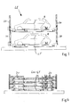
- the charge carriers which are already substantially known from DE 202 20 470 UI, are shown in FIG. 4 in a stacked form with the support columns 20 folded down. The exact structure will not be explained here.
- the forklift driver picks up one load carrier from each of these buffer locations and inserts it into the joining station FS. By means of sensors, a correct position of the charge carrier in the joining station is determined and a corresponding release signal is output.
- the forklift moves back behind a light barrier LS1.
- the driver of the forklift is no longer in a possible pivoting range of the gripper for the takeover of the body of the AGV.
- the lifting table HUB has moved into the takeover position for the gripper, whereby here too the upper lifting position is confirmed by position sensors.
- the gripper picks up the body and moves it to the position of the joining station, where it places it on the load carrier. If the body is sitting on the load carrier, the grab opens and releases the body.
- the gripper should also be available in the event of disruptions in the takeover of the body.
- the body is lifted back. If the body is handed over at the joining stations, the gripper moves back and the light barrier LS1 is switched off, which is signaled by a corresponding green traffic signal for the fork-lift driver.
- the forklift driver GST now drives into this area, picking up the load carrier with the body sitting thereon and driving with load carrier and body to a stacking station 12.
- the forklift uses the load carrier in the stacking station 12, he unfolds the lateral support columns 20, which by a appropriate mechanism are locked in this unfolded position.
- various conditions must be met. First, it must be checked whether the stacking station is in its basic position.
- an enable signal is output and a light barrier LS2 inactive, which in turn is signaled by a light signal to the forklift driver.
- a feed carriage ZW does not enter the area of the stacking station.
- This can be done, for example, by a third light barrier LS3, which outputs a signal to the control unit, not shown, when passing over the Zu manufacturedwagen ZW, so that it then stops the Zu manufacturedwagen ZW.
- the forklift GST can now enter the area of the stacking station 12 and set the first body with its load carrier in the stacking station 12. When the forklift GST has left the area again and is outside the light barrier LS2, this area is again in a safe mode and the stacking module 12 can lift the first body.
- This loading unit LE is picked up from the stacking station by a delivery truck ZW.
- the condition for this is that the light barrier LS2 is actively switched and the forklift is not located in the area in which the feed carriage moves.
- the Zu2020wagen itself runs on rails 13, which can be seen as in the figure 1, extending longitudinally through the entire loading arrangement.
- the Zutechnologywagen ZW moves up to the height of the stacking station 12 so that it is in its longitudinal orientation next to the stacking station.
- the Zurioswagen has on and executable Hubgabeln and chain conveyor, wherein the charge carrier engages by means of the Hubgabeln under the lower load carrier and lifts the load unit LE from the two load carriers vertically, so that then the chain conveyor a return of the load carrier on the feed carriage is possible.
- the ZW feed carriage travels on the rails to a free buffer space, of which there are essentially as many as wagging wagons can be loaded to the maximum.
- the buffer locations are indicated in FIG. 1 by the reference symbol PF.
- the Zurioswagen ZW begins with the storage of the load unit LE at the farthest from the stacking station 12 buffer space PF. In the event that all buffer locations are empty, this would be the buffer space PF1.
- Parallel to the feeder ZW moves on the opposite side of the buffer places a loader wagon LW. This loader also runs on rails. All steps are monitored by a control device that knows the current occupancy of the buffer locations and detects the retraction of the train consisting of several closed wagons W1, W2, W3, W4 and W5 for loading.
- the LW loader wagon has the function, after retracting the train and manually opening the wagon doors, to use a sensor system to check whether all wagons are actually empty.
- the loader wagon LW will therefore simultaneously detect in which of the wagons the stacked empty charge carriers are stored. On his return from the control of the waggons to his starting point 14, he will remove these empty load carriers empty LT from the wagons and place them accordingly in the designated places 15, 16, 17, 18 or 19.
- the loading of the wagons then begins in the way that the first occupied buffer spaces PF are discharged first and the last retracted wagon W5 is loaded first.
- the loader wagon LW moves to the height of the buffer PF1, and grips the loading unit LE, wherein the receiving takes place in turn via known pallet trucks and chain conveyors.
- the self-loading wagon sensors are provided, which detects the height of the wagon and the central orientation of the loading wagon to the car when loading. Then the loader wagon extends its outriggers so that the loading unit can be lowered into the wagon via chain conveyors.
- the control unit is always the current position of the individual carriers with Bogies, the hopper, the loading wagon and the waggons. Every body and each wagon is provided with a transponder, so that sensors accurate location can be recorded and assigned. It is thus in the transport protocol exactly known in which car which body is transported, so that the Wagons at a later discharge exactly in the order of how the bodies for the Manufacturing should be available.
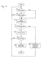
- FIG. 5 shows such an internal query in the control system as a flow chart, this flowchart being essentially applicable to all work steps to be sent out.
- step operation was not activated in step 21, as well as in the case of a positive answer to inquiry 22 as to whether a step release is to take place, in a subsequent step 23 the conditions for a step release from a corresponding memory section retrieved in the control system, so that it can be checked in a subsequent query 24, if the conditions for the step release, for example, whether in the stacking station no fork lift driver is more and in the stacking station two carriers with bodies to a cargo unit LE are given together. If this is the case, in step 25, the step is executed. If the conditions are not met, in step 28, an error detection and stepping operation is disabled. In step 26 of the flowchart, it is checked whether the executed step is finished.
- step 26 the next step to be executed is turned on and the program starts again. If no complete execution of the step to be executed has yet been detected in the work step, then the method returns to step 21. This will ensure that movement stops when conditions change during operation and can potentially endanger persons or objects.
Landscapes
- Automobile Manufacture Line, Endless Track Vehicle, Trailer (AREA)
- Loading Or Unloading Of Vehicles (AREA)
- Forklifts And Lifting Vehicles (AREA)
Abstract
Description
- Fig. 1
- die Anordnung zur Verladung im schematischen Überblick,
- Fig. 2
- die Übergabe der Karossen aus der Fertigungsstraße an eine Stapelstation,
- Fig. 3
- eine Ladeeinheit aus zwei Ladungsträgern mit Karossen
- Fig. 4
- gestapelte leere Ladungsträger
- Fig. 5
- die Funktionsbeschreibung eines Programmschrittes
Ein Hubwagen HUB, welcher unter der Endposition 11 angeordnet ist, hebt das ganze System FTF und Karosse soweit an, dass ein nicht dargestellter Greifer, welcher sich über diesem Hubtisch befindet, die Karosse aufnehmen kann. Daraufhin wird der Hubtisch wieder abgesenkt und das fahrerlose Transportfahrzeug FTF kann aus dem Bereich 10 wieder ausgefahren werden und erneut in der Fertigung der einzelnen Karossen zur Verfügung stehen.
Bevor der nicht dargestellte Greifer sich mit der Karosse weiterbewegt, erfolgt vom Steuergerät eine Kontrolle, ob in einer nachgeordneten Fügestation FS ein leerer Ladungsträger Leer-LT vorhanden ist. Die Fügestation FS bildet die technische Schnittstelle zwischen der Anlieferung der Karossen aus dem Fertigungsprozess per FTF und dem Absetzen der Karossen in einen Ladungsträger als kleinste Versandeinheit. Zur Vorbereitung der Fügestation FS für die Aufnahme einer Karosse holt ein manuell gesteuerter Gabelstapler GST einen leeren Ladungsträger Leer-LT aus einem entsprechenden Puffer ab. Zur Bereitstellung von Ladungsträgern befinden sich in einem Bereich der Verladeanordnung mehrere Pufferplätze 15, 16, 17, 18 und 19, auf welchen leere Ladungsträger gestapelt sind. Die Ladungsträger, die im wesentlichen bereits aus DE 202 20 470 Ulbekannt sind, sind in Figur 4 in gestapelter Form mit abgeklappten Stützsäulen 20 dargestellt. Der genaue Aufbau soll hier nicht erläutert werden. Von diesen Pufferplätzen holt der Gabelstaplerfahrer jeweils einen Ladungsträger ab und setzt ihn in die Fügestation FS ein. Mittels Sensoren wird eine Korrektlage des Ladungsträgers in der Fügestation ermittelt und ein entsprechendes Freigabesignal ausgegeben. Sitzt der Ladungsträger korrekt in der Fügestation, so fährt der Gabelstapler zurück hinter eine Lichtschranke LS1. Damit befindet sich der Fahrer des Gabelstaplers nicht mehr in einem möglichen Schwenkbereich des Greifers für die Übernahme der Karosse vom FTF. Der Hubtisch HUB ist in der Zwischenzeit in die Übernahmeposition für den Greifer gefahren, wobei auch hier die obere Hubposition durch Lagesensoren bestätigt wird. Anschließend nimmt der Greifer die Karosse auf und fährt sie in die Position der Fügestation, wo er sie auf den Ladungsträger absetzt. Sitzt die Karosse auf dem Ladungsträger, öffnet der Greifer und gibt die Karosse frei. Neben der Grundfunktion des Greifens zum Umsetzen der Fertigkarosse vom FTF zum Ladungsträger soll der Greifer auch für den Fall zur Verfügung stehen, wenn Störungen bei der Karossenübernahme auftreten. In diesem Fall erfolgt ein Zurückheben der Karosse. Ist die Karosse an den Fügestationen übergeben, fährt der Greifer zurück und die Lichtschranke LS1 wird ausgeschaltet, was durch entsprechendes grünes Ampelsignal für den Gabelstapelfahrer signalisiert wird. Der Gabelstaplerfahrer GST fährt nun in diesen Bereich ein, nimmt den Ladungsträger mit daraufsitzender Karosse auf und fährt mit Ladungsträger und Karosse zu einer Stapelstation 12. Bevor der Gabelstapler den Ladungsträger in die Stapelstation 12 einsetzt, klappt er die seitlichen Stützsäulen 20 auf, die durch eine entsprechende Mechanik in dieser aufgeklappten Position arretiert werden.
Für das Abstellen der einzelnen Ladungsträger mit Karossen in der Stapelstation 12 sind verschiedene Bedingungen zu erfüllen. Zunächst muss geprüft werden, ob die Stapelstation in ihrer Grundstellung ist. In diesem Fall wird ein Freigabesignal ausgegeben und eine Lichtschranke LS2 inaktiv geschaltet, was wiederum durch ein Lichtsignal an den Gabelstaplerfahrer signalisiert wird. Gleichzeitig wird sichergestellt, dass ein Zuführwagen ZW nicht in den Bereich der Stapelstation einfährt. Dies kann beispielsweise durch eine dritte Lichtschranke LS3 erfolgen, welche beim Überfahren durch den Zuführwagen ZW ein Signal an die nicht dargestellte Steuereinheit ausgibt, so dass diese dann den Zuführwagen ZW stoppt. Der Gabelstapler GST kann nun in den Bereich der Stapelstation 12 einfahren und die erste Karosse mit ihrem Ladungsträger in der Stapelstation 12 einstellen. Wenn der Gabelstapler GST den Bereich wieder verlassen hat, und sich außerhalb der Lichtschranke LS2 befindet, ist dieser Bereich wieder in einem Sicherheitsmodus und das Stapelmodul 12 kann die erste Karosse anheben. Sobald sich der Ladungsträger mit der Karosse in der obersten Hubposition des Stapelmoduls befindet, kann ein weiterer Ladungsträger mit Karosse, welcher in der Zwischenzeit nach dem oben beschriebenen Ablauf von der Endposition 11 übernommen und vom Gabelstapler aus der Fügestation FS aufgenommen wurde, in die Stapelstation 12 eingesetzt werde. Wenn auch dieser Ladungsträger ordnungsgemäß in der Stapelstation sitzt, wird der zuerst eingesetzte und angehobene obere Ladungsträger abgesenkt, so dass sie passgenau aufeinander stehen. Die beiden Ladungsträger LT mit Karossen K korrekt bilden eine Ladeeinheit LE. Anschließend verlässt der Gabelstapler wieder den Sicherheitsbereich und befindet sich zwischen den Lichtschranken LS1 und LS2. Das Stapelmodul 12 ist in der Fig. 1 nur aus der Vogelperspektive dargestellt, so dass hier die einzelnen Hubbewegungen nicht zu erkennen sind.
Der Zuführwagen ZW beginnt mit der Ablage der Ladungseinheit LE am von der Stapelstation 12 entferntesten Pufferplatz PF. Für den Fall, dass alle Pufferplätze leer sind, wäre dies der Pufferplatz PF1.
Parallel zu dem Zuführwagen ZW bewegt sich auf der gegenüberliegenden Seite der Pufferplätze ein Ladewagen LW. Dieser Ladewagen läuft ebenfalls auf Schienen. Alle Arbeitsschritte werden von einer Steuereinrichtung überwacht, die die augenblickliche Belegung der Pufferplätze kennt und die das Einfahren des aus mehreren geschlossenen Waggons W1, W2, W3, W4 und W5 bestehenden Zuges zum Beladen erfasst. Der Ladewagen LW hat die Funktion, nach dem Einfahren des Zuges und dem manuellen Öffnen der Waggontüren mittels einer Sensorik zu überprüfen, ob alle Waggons tatsächlich leer sind.
Die Beladung der Waggons beginnt dann in der Art, dass die zuerst belegten Pufferplätze PF als erstes entladen werden und der zuletzt eingefahrene Waggon W5 als erstes beladen wird. Hierzu fährt der Ladewagen LW auf die Höhe des Puffers PF1, und ergreift die Ladeeinheit LE, wobei die Aufnahme wiederum über bekannte Hubwagen und Kettenförderer erfolgt. An dem Ladewagen selbst sind Sensoren vorgesehen, die beim Beladen die Höhe des Waggons und die mittige Ausrichtung des Ladewagens zum Waggon erfasst. Anschließend fährt der Ladewagen seine Ausleger so aus, dass über Kettenförderer die Ladeinheit in den Waggon eingefahren werden kann.
In der Figur 5 ist eine solche interne Abfrage im Steuersystem als Ablaufplan dargestellt, wobei dieser Ablaufplan im wesentlichen auf alle auszusenden Arbeitsschritte anwendbar ist. Nach dem START wird zunächst im Schritt 21 abgefragt, ob der eine periphere Einheit, wie beispielsweise der Zuführwagen, sich in einem Schrittbetrieb befindet. Ist ein Schrittbetrieb aktiviert, dann wird im Arbeitsschritt 22 geprüft, ob eine Schrittfreigabe erfolgen soll. Ist dies nicht der Fall, wird zurückgesprungen zum Arbeitsschritt 21. Gleichzeitig wird, wenn in dem Arbeitsschritt 21 kein Schrittbetrieb aktiviert war, ebenso wie bei einer positiven Antwort auf die Abfrage 22, ob eine Schrittfreigabe erfolgt soll, in einem anschließendem Arbeitsschritt 23 die Bedingungen für eine Schrittfreigabe aus einem entsprechenden Speicherabschnitt im Steuersystem abgerufen, so dass in einer nachfolgenden Abfrage 24 geprüft werden kann, ob die Bedingungen für die Schrittfreigabe, beispielsweise ob sich im Bereich der Stapelstation kein Gabelstapelfahrer mehr befindet und in der Stapelstation zwei Ladungsträger mit Karossen zu einer Ladungseinheit LE zusammengefügt sind, gegeben sind. Ist dies der Fall, wird im Arbeitsschritt 25 der Schritt ausgeführt. Waren die Bedingungen nicht erfüllt, erfolgt im Arbeitsschritt 28 eine Fehlererkennung und der Schrittbetrieb wird gesperrt. Im Arbeitsschritt 26 des Ablaufplanes wird geprüft, ob der ausgeführte Schritt fertig ist. Ist dies der Fall , so wird anschließend im Arbeitsschritt 26 der nächste auszuführende Schritt eingeschaltet und das Programm beginnt erneut. Konnte im Arbeitsschritt noch keine vollständige Ausführung des auszuführenden Schrittes erkannt werden, dann springt das Verfahren zurück zum Arbeitsschritt 21.
Damit wird sichergestellt, dass eine Bewegung gestoppt wird, wenn während der Ausführung sich die Bedingungen ändern und es möglicherweise zur Gefährdung von Personen oder Gegenständen kommen kann.
Claims (7)
- Anordnung zum Verladen von Fahrzeugkarossen und dergleichen, wobei die montierten Karossen, welche stetig aus dem Fertigungsprozess zur Verladung bereitstehen, nach ihrer Endabnahme kontinuierlich abgenommen werden und zur Verladung vorbereitet werden, wobei mehrere verschieden Stationen der Verladeanordnung aufeinander abgestimmt und von einer Steuereinheit überwachbar sind, wobei die Karossen von einem Endpunkt einer Endkontrolle mittels des Zusammenwirkens eines Hubtisches und eines Greifers entnehmbar und auf einen vorbereiteten Ladungsträger absetzbar sind, wobei der Ladungsträger mit Karosse mittels eines Gabelstaplers in eine Fügestation einsetzbar ist und wobei in der Fügestation zwei Ladungsträger mit Karossen zu einer Ladeeinheit übereinanderstapelbar sind.
- Anordnung nach Anspruch 1, dadurch gekennzeichnet, dass die Ladeeinheit in Wagons (W1 bis W5) eines Transportfahrzeuges einladbar, wobei ein verfahrbarer Zuführwagen die Ladeeinheit aus der Fügestation mittels einer integrierter Hub- und Transportvorrichtung übernimmt und bis zum Einladen in das Transportfahrzeug auf einen Pufferplatz zwischenlagert.
- Anordnung nach Anspruch 2, dadurch gekennzeichnet, dass die Ladeeinheiten von einem verfahrbaren Ladewagen (LW) von dem Pufferplatz (PF) mittels einer integrierten Hub- und Transportvorrichtung aufnehmbar und in einen Waggon einsetzbar sind.
- Anordnung nach einem der vorherigen Ansprüche, dadurch gekennzeichnet, dass alle Karossen mit einer Identifikationsnummer versehen sind.
- Anordnung nach Anspruch 3, dadurch gekennzeichnet, dass jeder Waggon mit einer Identifikationsnummer versehen und somit kann jedem Waggon genau die Karosse zugeordnet werden kann, die in ihm eingeladen
- Anordnung nach einem der vorherigen Ansprüche, dadurch gekennzeichnet, dass die einzelnen Stationen der Verladeanordnung einer zentralen Steuereinheit überwachbar sind.
- Anordnung nach Anspruch 1, dadurch gekennzeichnet, dass Lichtschranken und Sensoren zur Erkennung von Endpositionen und zur Sicherung gefährlicher Bereiche vorgesehen sind.
Applications Claiming Priority (2)
| Application Number | Priority Date | Filing Date | Title |
|---|---|---|---|
| DE10347609 | 2003-10-09 | ||
| DE10347609A DE10347609A1 (de) | 2003-10-09 | 2003-10-09 | Anordnung zum Verladen von Fahrzeugkarossen |
Publications (2)
| Publication Number | Publication Date |
|---|---|
| EP1522510A1 true EP1522510A1 (de) | 2005-04-13 |
| EP1522510B1 EP1522510B1 (de) | 2006-05-17 |
Family
ID=34306387
Family Applications (1)
| Application Number | Title | Priority Date | Filing Date |
|---|---|---|---|
| EP04016709A Expired - Lifetime EP1522510B1 (de) | 2003-10-09 | 2004-07-15 | Anordnung zum Verladen von Fahrzeugkarossen |
Country Status (4)
| Country | Link |
|---|---|
| US (2) | US7547183B2 (de) |
| EP (1) | EP1522510B1 (de) |
| DE (2) | DE10347609A1 (de) |
| ES (1) | ES2260717T3 (de) |
Cited By (3)
| Publication number | Priority date | Publication date | Assignee | Title |
|---|---|---|---|---|
| US8107336B2 (en) | 2003-05-09 | 2012-01-31 | Lg Electronics Inc. | Write once optical disc, and method and apparatus for recovering disc management information from the write once optical disc |
| CN113979145A (zh) * | 2021-12-02 | 2022-01-28 | 江苏京天下电气科技有限公司 | 自动化叠料设备rgv对接整体布局 |
| EP4065453B1 (de) | 2019-11-25 | 2025-09-10 | Dürr Systems AG | Fördervorrichtung, bearbeitungsanlage, verfahren zum fördern und/oder bearbeiten von gegenständen |
Families Citing this family (14)
| Publication number | Priority date | Publication date | Assignee | Title |
|---|---|---|---|---|
| DE10347609A1 (de) * | 2003-10-09 | 2005-05-19 | Dr.Ing.H.C. F. Porsche Ag | Anordnung zum Verladen von Fahrzeugkarossen |
| DE102005023088B3 (de) * | 2005-05-13 | 2006-06-22 | Grammer Ag | Vorrichtung und Verfahren zur Federung eines Fahrzeugsitzes mittels Zusatzvolumina |
| US20070264097A1 (en) * | 2006-05-11 | 2007-11-15 | Progressive Rail | Systems and methods for loading and transporting freight and dunnage on railcars |
| DE102008020083A1 (de) | 2008-04-22 | 2009-10-29 | Dr. Ing. H.C. F. Porsche Aktiengesellschaft | Verfahren zur Fertigung von Kraftfahrzeugen |
| DE102008033334A1 (de) | 2008-07-16 | 2010-01-21 | Dr. Ing. H.C. F. Porsche Aktiengesellschaft | Verfahren zur Entladung von Fahrzeugkarossen aus einem Transportmittel |
| US10287114B2 (en) * | 2013-01-30 | 2019-05-14 | Nathan J. Sonnenfeld | Methods, systems and apparatuses for loading and unloading freight from railcars |
| JP2016056003A (ja) * | 2014-09-10 | 2016-04-21 | 株式会社椿本チエイン | 組立搬送装置 |
| JP2016098069A (ja) * | 2014-11-20 | 2016-05-30 | ダイハツ工業株式会社 | オーバーヘッドコンベア装置 |
| DE102015109163A1 (de) * | 2015-06-10 | 2016-12-15 | Dr. Ing. H.C. F. Porsche Aktiengesellschaft | Verfahren zum vollautomatischen Prüfen eines Ladungsträgers |
| JP7021765B2 (ja) * | 2017-05-08 | 2022-02-17 | 秀樹 取田 | 交通システム及び輸送方法 |
| US10146226B1 (en) | 2017-08-04 | 2018-12-04 | Ford Global Technologies, Llc | Autonomous vehicle sequential railcar loading and alignment |
| US10620630B2 (en) | 2017-08-24 | 2020-04-14 | Ford Global Technologies, Llc | Moving vehicles on and off transport carriages |
| CN107585457B (zh) * | 2017-09-14 | 2023-05-05 | 大连中集特种物流装备有限公司 | 汽车运输架 |
| CN112744362B (zh) * | 2020-12-29 | 2023-04-14 | 中国航空工业集团公司西安飞机设计研究所 | 一种传感器-载荷机构-阻尼器一体化装置 |
Citations (3)
| Publication number | Priority date | Publication date | Assignee | Title |
|---|---|---|---|---|
| DE3616484A1 (de) * | 1986-05-15 | 1987-11-19 | Schlimm Norbert Dipl Ing | Anlage zum be- und entladen von kraftfahrzeugen und lasten auf ein und von einem schienenfahrzeug |
| DE20220470U1 (de) * | 2002-01-12 | 2003-08-14 | Dr.Ing.H.C. F. Porsche Ag, 70435 Stuttgart | Transporteinrichtung |
| DE20220469U1 (de) * | 2002-05-16 | 2003-09-04 | Dr.Ing.H.C. F. Porsche Ag, 70435 Stuttgart | Be- und Entladestation für Ladungsträger von Fahrzeugkarossen, Fahrzeugen u.dgl. |
Family Cites Families (8)
| Publication number | Priority date | Publication date | Assignee | Title |
|---|---|---|---|---|
| US3212654A (en) * | 1963-11-21 | 1965-10-19 | Lansing Bagnall Ltd | Apparatus for loading and unloading goods |
| GB1505992A (en) * | 1975-07-17 | 1978-04-05 | Asea Ab | Means for handling vehicle-carrying pallets or like platforms |
| US4652205A (en) * | 1985-05-02 | 1987-03-24 | Robotic Vision Systems, Inc. | Robot cell safety system |
| JP2722944B2 (ja) * | 1992-06-05 | 1998-03-09 | 三菱自動車工業株式会社 | ワーク搬送システム |
| US5953234A (en) * | 1996-03-12 | 1999-09-14 | Woodson Incorporated | Automated storage facility including a storage and retrieval system and a floor inventory management system |
| US6148291A (en) * | 1998-01-26 | 2000-11-14 | K & T Of Lorain, Ltd. | Container and inventory monitoring methods and systems |
| US6619907B1 (en) * | 2000-11-21 | 2003-09-16 | General Motors Corporation | Method and apparatus for unloading and reloading returnable shipping containers from a trailer |
| DE10347609A1 (de) * | 2003-10-09 | 2005-05-19 | Dr.Ing.H.C. F. Porsche Ag | Anordnung zum Verladen von Fahrzeugkarossen |
-
2003
- 2003-10-09 DE DE10347609A patent/DE10347609A1/de not_active Withdrawn
-
2004
- 2004-07-15 DE DE502004000576T patent/DE502004000576D1/de not_active Expired - Lifetime
- 2004-07-15 EP EP04016709A patent/EP1522510B1/de not_active Expired - Lifetime
- 2004-07-15 ES ES04016709T patent/ES2260717T3/es not_active Expired - Lifetime
- 2004-10-12 US US10/961,367 patent/US7547183B2/en not_active Expired - Lifetime
-
2009
- 2009-06-08 US US12/479,990 patent/US8038381B2/en not_active Expired - Lifetime
Patent Citations (3)
| Publication number | Priority date | Publication date | Assignee | Title |
|---|---|---|---|---|
| DE3616484A1 (de) * | 1986-05-15 | 1987-11-19 | Schlimm Norbert Dipl Ing | Anlage zum be- und entladen von kraftfahrzeugen und lasten auf ein und von einem schienenfahrzeug |
| DE20220470U1 (de) * | 2002-01-12 | 2003-08-14 | Dr.Ing.H.C. F. Porsche Ag, 70435 Stuttgart | Transporteinrichtung |
| DE20220469U1 (de) * | 2002-05-16 | 2003-09-04 | Dr.Ing.H.C. F. Porsche Ag, 70435 Stuttgart | Be- und Entladestation für Ladungsträger von Fahrzeugkarossen, Fahrzeugen u.dgl. |
Cited By (3)
| Publication number | Priority date | Publication date | Assignee | Title |
|---|---|---|---|---|
| US8107336B2 (en) | 2003-05-09 | 2012-01-31 | Lg Electronics Inc. | Write once optical disc, and method and apparatus for recovering disc management information from the write once optical disc |
| EP4065453B1 (de) | 2019-11-25 | 2025-09-10 | Dürr Systems AG | Fördervorrichtung, bearbeitungsanlage, verfahren zum fördern und/oder bearbeiten von gegenständen |
| CN113979145A (zh) * | 2021-12-02 | 2022-01-28 | 江苏京天下电气科技有限公司 | 自动化叠料设备rgv对接整体布局 |
Also Published As
| Publication number | Publication date |
|---|---|
| US8038381B2 (en) | 2011-10-18 |
| US7547183B2 (en) | 2009-06-16 |
| ES2260717T3 (es) | 2006-11-01 |
| EP1522510B1 (de) | 2006-05-17 |
| US20050102813A1 (en) | 2005-05-19 |
| DE502004000576D1 (de) | 2006-06-22 |
| DE10347609A1 (de) | 2005-05-19 |
| US20090248197A1 (en) | 2009-10-01 |
Similar Documents
| Publication | Publication Date | Title |
|---|---|---|
| EP1522510B1 (de) | Anordnung zum Verladen von Fahrzeugkarossen | |
| EP2151403B1 (de) | Logistiksystem | |
| EP3166817B1 (de) | Schwerlast-transportfahrzeug für container, insbesondere iso-container, und verfahren zum beladen desselben | |
| DE102010028821B4 (de) | Verfahren zum Be- und Entladen von Fahrzeugen sowie Logistiksysteme mit Übergabestation | |
| EP1539619B1 (de) | Verfahren zum be- und entladen | |
| WO2020182699A1 (de) | Regalbediengerät zum verladen von stapelfähigen waren und logistiksystem mit einem solchen regalbediengerät | |
| WO2006018242A2 (de) | Güterumschlagverfahren und transportsystem | |
| DE102009049563A1 (de) | Shuttle-Kanallager, Shuttle-Bahnhof, Shuttle und Verfahren zum Betreiben des Shuttle-Kanallagers | |
| EP0831002A1 (de) | Vorrichtung zum Horizontal-Umschlag von Lasten | |
| DE10221733B4 (de) | Be- und Entladestation für Ladungsträger von Fahrzeugkarossen, Fahrzeugen und dergleichen | |
| DE102015111650A1 (de) | Erntesystem mit automatischem Transportkistenwechsel | |
| DE2645195C2 (de) | Übergabevorrichtung | |
| DE102010040152A1 (de) | Vorrichtung zum Umsetzen von Ladungsträgern und Beladestation | |
| DE102017000274A1 (de) | Untergestell für einen Großladungsträger sowie Verfahren zum Transportieren zumindest eines Großladungsträgers | |
| DE102010043916A1 (de) | Vorrichtung zum Behandeln von transmodalen Transporteinheiten | |
| EP2581312B1 (de) | Containertransporter | |
| EP0426691B1 (de) | Transportfahrzeug mit lastverschiebe-ruecksatz mit in der laenge veraenderbaren schubmitteln | |
| DE102018100734B4 (de) | Transportwagen-Beladestation | |
| EP2113450B1 (de) | Fertigungslinie zur Herstellung von Kraftfahrzeugen | |
| EP2113452B1 (de) | Fertigungslinie zur Herstellung von Kraftfahrzeugen | |
| DE102015121804B4 (de) | Transportfahrzeug für Container | |
| DE102014108016A1 (de) | Verfahren zum Be- und Entladen eines Routenzugs | |
| EP2113451B1 (de) | Vorrichtung und Verfahren zur Herstellung von Kraftfahrzeugen | |
| EP3628612B1 (de) | Ladeeinrichtung zum heckseitigen beladen eines lkws | |
| EP4509439A1 (de) | Übergabestation für lasten in logistikeinrichtungen |
Legal Events
| Date | Code | Title | Description |
|---|---|---|---|
| PUAI | Public reference made under article 153(3) epc to a published international application that has entered the european phase |
Free format text: ORIGINAL CODE: 0009012 |
|
| AK | Designated contracting states |
Kind code of ref document: A1 Designated state(s): AT BE BG CH CY CZ DE DK EE ES FI FR GB GR HU IE IT LI LU MC NL PL PT RO SE SI SK TR |
|
| AX | Request for extension of the european patent |
Extension state: AL HR LT LV MK |
|
| GRAP | Despatch of communication of intention to grant a patent |
Free format text: ORIGINAL CODE: EPIDOSNIGR1 |
|
| 17P | Request for examination filed |
Effective date: 20051013 |
|
| AKX | Designation fees paid |
Designated state(s): DE ES FR GB IT SE |
|
| GRAS | Grant fee paid |
Free format text: ORIGINAL CODE: EPIDOSNIGR3 |
|
| GRAA | (expected) grant |
Free format text: ORIGINAL CODE: 0009210 |
|
| AK | Designated contracting states |
Kind code of ref document: B1 Designated state(s): DE ES FR GB IT SE |
|
| REG | Reference to a national code |
Ref country code: GB Ref legal event code: FG4D Free format text: NOT ENGLISH |
|
| REG | Reference to a national code |
Ref country code: SE Ref legal event code: TRGR |
|
| REF | Corresponds to: |
Ref document number: 502004000576 Country of ref document: DE Date of ref document: 20060622 Kind code of ref document: P |
|
| GBT | Gb: translation of ep patent filed (gb section 77(6)(a)/1977) |
Effective date: 20060810 |
|
| ET | Fr: translation filed | ||
| REG | Reference to a national code |
Ref country code: ES Ref legal event code: FG2A Ref document number: 2260717 Country of ref document: ES Kind code of ref document: T3 |
|
| PLBE | No opposition filed within time limit |
Free format text: ORIGINAL CODE: 0009261 |
|
| STAA | Information on the status of an ep patent application or granted ep patent |
Free format text: STATUS: NO OPPOSITION FILED WITHIN TIME LIMIT |
|
| 26N | No opposition filed |
Effective date: 20070220 |
|
| REG | Reference to a national code |
Ref country code: GB Ref legal event code: 732E |
|
| REG | Reference to a national code |
Ref country code: FR Ref legal event code: TP |
|
| REG | Reference to a national code |
Ref country code: GB Ref legal event code: 732E Free format text: REGISTERED BETWEEN 20090326 AND 20090401 |
|
| REG | Reference to a national code |
Ref country code: FR Ref legal event code: TP |
|
| REG | Reference to a national code |
Ref country code: GB Ref legal event code: 732E Free format text: REGISTERED BETWEEN 20090924 AND 20090930 |
|
| REG | Reference to a national code |
Ref country code: FR Ref legal event code: CD |
|
| REG | Reference to a national code |
Ref country code: FR Ref legal event code: TQ |
|
| REG | Reference to a national code |
Ref country code: GB Ref legal event code: 732E Free format text: REGISTERED BETWEEN 20110310 AND 20110316 |
|
| REG | Reference to a national code |
Ref country code: GB Ref legal event code: 732E Free format text: REGISTERED BETWEEN 20110331 AND 20110406 |
|
| REG | Reference to a national code |
Ref country code: FR Ref legal event code: TQ |
|
| REG | Reference to a national code |
Ref country code: FR Ref legal event code: PLFP Year of fee payment: 13 |
|
| REG | Reference to a national code |
Ref country code: FR Ref legal event code: PLFP Year of fee payment: 14 |
|
| REG | Reference to a national code |
Ref country code: DE Ref legal event code: R081 Ref document number: 502004000576 Country of ref document: DE Owner name: DR. ING. H.C. F. PORSCHE AKTIENGESELLSCHAFT, DE Free format text: FORMER OWNERS: DR. ING. H.C. F. PORSCHE AKTIENGESELLSCHAFT, 70435 STUTTGART, DE; ILS INDUSTRIE LOGISTIC SWISS AG, PFAEFFIKON, CH |
|
| REG | Reference to a national code |
Ref country code: FR Ref legal event code: PLFP Year of fee payment: 15 |
|
| PGFP | Annual fee paid to national office [announced via postgrant information from national office to epo] |
Ref country code: FR Payment date: 20190719 Year of fee payment: 16 Ref country code: SE Payment date: 20190719 Year of fee payment: 16 Ref country code: IT Payment date: 20190730 Year of fee payment: 16 Ref country code: ES Payment date: 20190822 Year of fee payment: 16 |
|
| PGFP | Annual fee paid to national office [announced via postgrant information from national office to epo] |
Ref country code: GB Payment date: 20190719 Year of fee payment: 16 |
|
| REG | Reference to a national code |
Ref country code: SE Ref legal event code: EUG |
|
| GBPC | Gb: european patent ceased through non-payment of renewal fee |
Effective date: 20200715 |
|
| PG25 | Lapsed in a contracting state [announced via postgrant information from national office to epo] |
Ref country code: FR Free format text: LAPSE BECAUSE OF NON-PAYMENT OF DUE FEES Effective date: 20200731 Ref country code: GB Free format text: LAPSE BECAUSE OF NON-PAYMENT OF DUE FEES Effective date: 20200715 |
|
| PG25 | Lapsed in a contracting state [announced via postgrant information from national office to epo] |
Ref country code: SE Free format text: LAPSE BECAUSE OF NON-PAYMENT OF DUE FEES Effective date: 20200716 |
|
| PGFP | Annual fee paid to national office [announced via postgrant information from national office to epo] |
Ref country code: DE Payment date: 20210705 Year of fee payment: 18 |
|
| REG | Reference to a national code |
Ref country code: ES Ref legal event code: FD2A Effective date: 20211228 |
|
| PG25 | Lapsed in a contracting state [announced via postgrant information from national office to epo] |
Ref country code: ES Free format text: LAPSE BECAUSE OF NON-PAYMENT OF DUE FEES Effective date: 20200716 |
|
| PG25 | Lapsed in a contracting state [announced via postgrant information from national office to epo] |
Ref country code: IT Free format text: LAPSE BECAUSE OF NON-PAYMENT OF DUE FEES Effective date: 20200715 |
|
| REG | Reference to a national code |
Ref country code: DE Ref legal event code: R119 Ref document number: 502004000576 Country of ref document: DE |
|
| PG25 | Lapsed in a contracting state [announced via postgrant information from national office to epo] |
Ref country code: DE Free format text: LAPSE BECAUSE OF NON-PAYMENT OF DUE FEES Effective date: 20230201 |