EP1522348B1 - Procédé et système d'alimentation en produit d'un dispositif consommateur par un circuit nettoyé par raclage - Google Patents
Procédé et système d'alimentation en produit d'un dispositif consommateur par un circuit nettoyé par raclage Download PDFInfo
- Publication number
- EP1522348B1 EP1522348B1 EP04023410A EP04023410A EP1522348B1 EP 1522348 B1 EP1522348 B1 EP 1522348B1 EP 04023410 A EP04023410 A EP 04023410A EP 04023410 A EP04023410 A EP 04023410A EP 1522348 B1 EP1522348 B1 EP 1522348B1
- Authority
- EP
- European Patent Office
- Prior art keywords
- valve device
- pigged
- accordance
- supply systems
- single supply
- Prior art date
- Legal status (The legal status is an assumption and is not a legal conclusion. Google has not performed a legal analysis and makes no representation as to the accuracy of the status listed.)
- Expired - Lifetime
Links
Images

Classifications
-
- B—PERFORMING OPERATIONS; TRANSPORTING
- B05—SPRAYING OR ATOMISING IN GENERAL; APPLYING FLUENT MATERIALS TO SURFACES, IN GENERAL
- B05B—SPRAYING APPARATUS; ATOMISING APPARATUS; NOZZLES
- B05B12/00—Arrangements for controlling delivery; Arrangements for controlling the spray area
- B05B12/14—Arrangements for controlling delivery; Arrangements for controlling the spray area for supplying a selected one of a plurality of liquids or other fluent materials or several in selected proportions to a spray apparatus, e.g. to a single spray outlet
- B05B12/1481—Arrangements for controlling delivery; Arrangements for controlling the spray area for supplying a selected one of a plurality of liquids or other fluent materials or several in selected proportions to a spray apparatus, e.g. to a single spray outlet comprising pigs, i.e. movable elements sealingly received in supply pipes, for separating different fluids, e.g. liquid coating materials from solvent or air
-
- B—PERFORMING OPERATIONS; TRANSPORTING
- B05—SPRAYING OR ATOMISING IN GENERAL; APPLYING FLUENT MATERIALS TO SURFACES, IN GENERAL
- B05B—SPRAYING APPARATUS; ATOMISING APPARATUS; NOZZLES
- B05B5/00—Electrostatic spraying apparatus; Spraying apparatus with means for charging the spray electrically; Apparatus for spraying liquids or other fluent materials by other electric means
- B05B5/16—Arrangements for supplying liquids or other fluent material
Definitions
- the invention relates to a method and a system for supplying material consumers, in particular for the ink supply of coating devices, according to the preamble of the independent claims.
- material consumers in particular for the ink supply of coating devices, according to the preamble of the independent claims.
- it is the series coating of workpieces such as vehicle bodies with possibly electrically conductive coating material, in which the first group of materials can be formed by the different standard or series colors and the additional material group by different special colors.
- the nebulizers of the vehicle body coating systems are known to be fed from loop lines to which they are connected by stubs and color changers which may be located within the spray booth at or near the painting robots or other coating machines.
- the stub lines are expediently designed as pig tracks in modern coating systems ( DE 101 31 562 . DE 101 57 966 etc.).
- special colors which are pumped from separate color containers located in the color mixing chamber outside the booth directly through their own stub lines to the atomizer removal points, which may be designed as color changers ( DE 196 32 325 , and the generic DE 100 06 310 ).
- spur lines are pigging lines, so that, for example, in a conventional manner filled a predetermined amount of paint in the line and promoted in the so-called pushout operation to the sampling or not sprayed paint from the line in the so-called reflow operation in the Paint tank can be backfelt.
- the pig pipes required for this purpose take up a great deal of space, and since hitherto a separate piggyback route to the removal point is required for each special color, considerable expense for the pigging lines and their pigging stations also results for a larger number of special colors.
- this effort by the large space requirement in the paint mixing chamber and in the valve cabinets and the limited space available for the laying of pigging hoses, the number of possible special shades is undesirable limited.
- the invention has for its object to reduce in processes and systems for material supply in particular of the type described above required for a given number of selectable additional materials overhead and space requirements of the pig lines and to increase the efficiency of existing gemold lines.
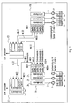
- FIG. 1 Scheme shown can form single or additional color supply systems for special colors, for example in a paint shop for the series coating of vehicle bodies.
- A1, A2 and An denote a number n of color containers for different colors, which are each connected via a pump P to a color distributor FA formed by a valve device. At least the two containers A1 and A2 and in practice only a few further containers are connected to the paint distributor FA, but the total number n per se is arbitrary. The larger the number n, the fewer pigging distances are required.
- each of these central channels can be connected at a pig source station MQ11 to the input of a common line ML11 which leads to the removal point E1 at which the pig target station MZ11 of the line ML11 is located.
- the line ML11 can lead into a central channel Za or into another channel Zb, which can lead to one or more atomizers, which are to be supplied from the containers A1, A2 or An via the common line ML11 common to the respective spot colors ,
- the removal point E1 is similar to the color distributor FA designed as a valve unit and can in particular a usual in supply systems of the type considered connected to Ring effetsmakersssysteme color changer for standard or series colors with the optionally usable, separately flushable central channels Za and Zb upstream of the color distributor FA on the gemgled line ML11 or on the central channels Za or Zb can be connected in parallel.
- the paint distributor FA expediently one or more further pigging lines each with a gemold line such as ML12 and their source and destination stations MQ12, MZ12 connected to connect the color distributor FA with one or more other sampling points such as E2 to which additional atomizers are connected.
- the removal points E1, E2, etc. are located on the manual and / or mechanical, optionally electrostatic, painting zones following one another in the usual way along a painting booth.
- the pig-pig stations of the lines leading to not shown further sampling points are denoted by MQ13, MQ14 and MQ1m, where m can be any number.
- the removal points E1, E2 etc. can be located outside or in the spray booth, for example on a robot arm or on or in the vicinity of other painting machines, while the paint distributor FA is always arranged outside the booth in the example considered here.
- each removal point such as E1 and E2
- further color distributors likewise supplied in each case by individual color supply systems, can be connected in accordance with FA.
- the molten line ML21 is connected to the removal point E1 at the further pig destination station MZ21, whose pig source station MQ21 is in the color distributor FB is located.
- the color distributor FB can be identical to the color distributor FA and thus also contain central channels connected to at least two to n individual color supply systems, each with a container B1, B2, Bn and associated pump P.
- the second color distributor FB is also connected to the removal point E2 via the gemged line ML22 with source and destination stations MQ22 and MZ22.
- the containers B1, B2, Bn may contain different colors than the containers connected to the paint distributor FA, but may u. U. in containers of different color distribution also be the same colors.
- One advantage of the arrangement shown is, inter alia, that, for example, during the supply of the removal point E1 from the color distributor FA already provided a special color for the other color distributor FB and from this even up to the removal point E1 can be pressed, so this for the subsequent coating with a new material without loss of time can be prepared.
- Fig. 2 the valve scheme of one of the color distributors such as FA or FB is shown, which may include a pig feeder station such as MQ11 with, for example, three or two pigs MP and MR as shown, to which the common line ML11 leading to the take-off point E1 is connected.
- the pigs are mechanically positioned by a cylinder unit QZY.
- the mentioned further source stations MQ12 to MQ1m are in Fig. 2 not shown.
- valves for detergent and pulsed air are shown for rinsing the paint distributor.
- the dashed lines represent the e.g. pneumatic control lines of the valves.
- this material is pumped by manual or automatic control with the pump P into the central channel Z1 of the paint distributor FA, which first opens with the valves QFa and QFM open and with the return valve QRFM (FIG. Fig. 2 ) is filled. After this pressing of the existing pump, central channel and return pump circuit, the return valve QRFM is closed, whereupon the color material between the pigs MP and MR through the line ML11 is promoted to the discharge point E1 for pressing the pig track, so that there for delivery the atomizer is ready.
- the paint delivery between pigs possibly with pushout through the rear pig MP is known per se and therefore need not be described in detail.
- the line ML11 and its pig stations can be rinsed separately via the valves provided so that they are immediately available again for repressurization via another central channel Z2 or Zn, even if in the pump circuit of the central channel Z1 still Color is located.
- the pump circuit consisting of pump P, the central channel such as Z1 and the associated feedback is also purged.
- the single supply systems can be operated independently under manual or automatic control. For example, while one system is pressed, the other system may be in the paint or rinse state.
- both the individual supply systems including the central channels such as Z1, Z2 and Zn as well as the pig tracks formed by the lines such as ML11 can each be independently rinsed and filled with material, i. Irrespective of the rinsing or filling of the respective other elements, there are significant advantages, in particular the least possible loss of time during a color or material change.
- the invention is not limited to the paint supply described, but suitable for any other material supply systems with pig tracks.
Landscapes
- Spray Control Apparatus (AREA)
- Application Of Or Painting With Fluid Materials (AREA)
- Coating Apparatus (AREA)
Claims (14)
- Procédé d'alimentation de consommateurs de matériau avec différents matériaux via des voies de raclage, en particulier pour acheminer la peinture vers des dispositifs destinés au revêtement de pièces avec des matériaux de couleurs différentes, dans lequel, au choix,
un matériau issu d'un premier groupe de matériaux
ou au moins deux matériaux différents, appartenant à un deuxième groupe de matériaux supplémentaire et provenant de systèmes d'alimentation individuels (A1, A2, An) en passant par un système de conduites raclées (ML11),
sont acheminés vers un point de prélèvement (E1) des consommateurs,
caractérisé en ce que lesdits au moins deux matériaux différents sont guidés hors de leurs systèmes d'alimentation individuels (A1, A2, An) vers un dispositif à vannes (FA) commandé pour choisir le matériau souhaité dans chaque cas et, à partir de là, sont acheminés à travers la conduite raclée (ML11), qui leur est commune, vers le point de prélèvement (E1). - Procédé selon la revendication 1, caractérisé en ce que par la commande des vannes, les systèmes d'alimentation individuels (A1, A2, An ; P ; Z1 Z2 ; Zn) et la conduite raclée (ML11) sont rincés et sont remplis avec un matériau respectivement de manière autarcique.
- Procédé selon la revendication 1 ou 2, caractérisé en ce que le matériau est pompé directement vers le dispositif à vannes (FA) par des pompes (P) raccordées à des réservoirs de matériau (A1, A2, An) des systèmes d'alimentation individuels supplémentaires.
- Procédé selon l'une quelconque des revendications précédentes, caractérisé en ce que le matériau des systèmes d'alimentation individuels supplémentaires est acheminé hors du dispositif à vannes (FA) via respectivement une conduite raclée (ML11, ML12) vers une pluralité de points de prélèvement (E1, E2).
- Procédé selon l'une quelconque des revendications précédentes, caractérisé en ce que chaque point de prélèvement (E1) est alimenté via respectivement une conduite raclée (ML11, ML12) à partir d'au moins deux dispositifs à vannes (FA, FB) raccordés chacun à des systèmes d'alimentation individuels (A1, A2, An ; B1, B2, Bn).
- Système destiné à alimenter des consommateurs de matériau avec différents matériaux via des voies de raclage, en particulier pour acheminer la peinture vers des dispositifs destinés au revêtement de pièces avec des matériaux de couleurs différentes, dans lequel, au choix,
un matériau issu d'un premier groupe de matériaux
ou au moins deux matériaux différents, appartenant à un deuxième groupe de matériaux supplémentaire et provenant de systèmes d'alimentation individuels (A1, A2, An) en passant par un système de conduites raclées (ML11),
sont acheminés vers un point de prélèvement (E1) des consommateurs,
caractérisé en ce que, entre les systèmes d'alimentation individuels (A1, A2, An) supplémentaires et la conduite raclée (ML11), est monté un dispositif à vannes (FA) par lequel les systèmes d'alimentation individuels (A1, A2, An) supplémentaires peuvent être raccordés au choix à la conduite raclée (ML11) qui leur est commune. - Système selon la revendication 6, caractérisé en ce que le dispositif à vannes (FA) comporte deux ou plus de canaux (Z1, Z2, Zn), qui sont raccordés respectivement à l'un des systèmes d'alimentation individuels et auxquels la conduite raclée (ML11) peut être raccordée de manière sélective via des vannes (QFa, QFb, QFc) commandées, et en ce que, par la commande des vannes, la conduite raclée (ML11) et les canaux (Z1, Z2, Zn) peuvent être rincés et remplis avec un matériau, dans chaque cas indépendamment les uns des autres.
- Système selon la revendication 6 ou 7, caractérisé en ce que le dispositif à vannes (FA) est disposé à proximité des réservoirs de matériau (A1, A2, An) des systèmes d'alimentation individuels supplémentaires en dehors d'une cabine de pulvérisation, dans laquelle sont situés le point de prélèvement (E1) et/ou un dispositif d'application raccordé au point de prélèvement, et une pompe (P) est montée entre les réservoirs de matériau (A1, A2, An) et le dispositif à vannes (FA).
- Système selon l'une quelconque des revendications 6 à 8, caractérisé en ce que le dispositif à vannes (FA) est réalisé sous la forme d'un distributeur de matériaux, à partir duquel respectivement une conduite raclée (ML11, ML12) mène vers plusieurs points de prélèvement (E1, E2).
- Système selon l'une quelconque des revendications 6 à 9, caractérisé en ce que chaque point de prélèvement (E1, E2) est relié à au moins deux systèmes de vannes (FA, FB) raccordés chacun à des systèmes d'alimentation individuels (A1, A2, An ; B1, B2, Bn) supplémentaires.
- Système selon l'une quelconque des revendications 6 à 10, caractérisé en ce que le dispositif à vannes (FA, FB) comporte au moins un poste de lancement du racleur (MQ11) pour la conduite raclée (ML11) raccordée.
- Système selon l'une quelconque des revendications 6 à 11, caractérisé en ce que, sur ou dans le point de prélèvement (E1, E2), il est prévu un dispositif à vannes pour changement de peinture (Za, Zb), raccordé à des conduites annulaires pour le premier groupe de matériau, et en ce que le point de prélèvement comporte des vannes commandées, par l'intermédiaire desquelles le consommateur ou chaque consommateur raccordé sont alimentés au choix avec les matériaux du premier groupe ou ceux du deuxième groupe.
- Système selon l'une quelconque des revendications 6 à 12, caractérisé en ce que le dispositif à vannes (FA) comporte des vannes (QFa, QFb, QFc, QFM) commandées, par lesquelles les canaux (Z1, Z2, Zn) du dispositif à vannes (FA), alimentés par les réservoirs de matériau (A1, A2, An) raccordés, peuvent être reliés au choix avec chacune des conduites raclées (ML11, ML12) parmi la pluralité de conduites raclées raccordées au dispositif à vannes (FA).
- Dispositif à vannes pour un système selon l'une quelconque des revendications 6 à 13, caractérisé en ce que ledit dispositif comporte des vannes (QFa, QFb, QFc, QFM) commandées, par lesquelles des canaux (Z1, Z2, Zn) contenus en plus dans le dispositif à vannes, peuvent être reliés au choix avec le canal de sortie (ML 11) d'un ou de plusieurs postes de lancement du racleur (MQ 11), contenus dans le dispositif à vannes.
Priority Applications (1)
| Application Number | Priority Date | Filing Date | Title |
|---|---|---|---|
| PL04023410T PL1522348T3 (pl) | 2003-10-07 | 2004-10-01 | Sposób i system zasilania odbiorników materiału poprzez odcinki piggingowe |
Applications Claiming Priority (2)
| Application Number | Priority Date | Filing Date | Title |
|---|---|---|---|
| DE10346601A DE10346601A1 (de) | 2003-10-07 | 2003-10-07 | Verfahren und System zur Versorgung von Materialverbrauchern über Molchstrecken |
| DE10346601 | 2003-10-07 |
Publications (3)
| Publication Number | Publication Date |
|---|---|
| EP1522348A2 EP1522348A2 (fr) | 2005-04-13 |
| EP1522348A3 EP1522348A3 (fr) | 2008-01-23 |
| EP1522348B1 true EP1522348B1 (fr) | 2009-07-22 |
Family
ID=34306312
Family Applications (1)
| Application Number | Title | Priority Date | Filing Date |
|---|---|---|---|
| EP04023410A Expired - Lifetime EP1522348B1 (fr) | 2003-10-07 | 2004-10-01 | Procédé et système d'alimentation en produit d'un dispositif consommateur par un circuit nettoyé par raclage |
Country Status (3)
| Country | Link |
|---|---|
| EP (1) | EP1522348B1 (fr) |
| DE (2) | DE10346601A1 (fr) |
| PL (1) | PL1522348T3 (fr) |
Families Citing this family (2)
| Publication number | Priority date | Publication date | Assignee | Title |
|---|---|---|---|---|
| WO2009115201A2 (fr) | 2008-03-20 | 2009-09-24 | Dürr Systems GmbH | Robot de peinture et procédé d'utilisation correspondant |
| DE102023102825A1 (de) | 2023-02-06 | 2024-08-08 | Dürr Systems Ag | Beschichtungsmittel-Versorgungseinrichtung und zugehöriges Betriebsverfahren |
Family Cites Families (10)
| Publication number | Priority date | Publication date | Assignee | Title |
|---|---|---|---|---|
| DE19632325A1 (de) | 1996-08-10 | 1998-02-12 | Herberts Gmbh | Vorrichtung zur Lackierung von Kraftfahrzeugkarossen |
| DE19742588B4 (de) * | 1997-09-26 | 2009-02-19 | Dürr Systems GmbH | Verfahren zum serienweisen Beschichten von Werkstücken |
| DE19830029A1 (de) * | 1998-07-04 | 2000-01-05 | Audi Ag | Anlage zum Beschichten von Gegenständen, insbesondere von Fahrzeug-Karosserien |
| DE19937474C2 (de) * | 1999-08-07 | 2001-08-02 | Eisenmann Lacktechnik Kg | Lackiervorrichtung mit einer Pistoleneinheit, einer Farbwechseleinrichtung und einer molchbaren Verbindungseinrichtung |
| DE10006310A1 (de) * | 2000-02-12 | 2001-08-16 | Lactec Gmbh | Verfahren und Vorrichtung zum Beschichten |
| DE10033987A1 (de) * | 2000-07-13 | 2002-01-24 | Duerr Systems Gmbh | Verfahren zur Versorgung eines Beschichtungsorgans für die elektrostatische Serienbeschichtung von Werkstücken und Versorgungssystem hierfür |
| DE10059041C2 (de) * | 2000-11-28 | 2002-11-14 | Lactec Ges Fuer Moderne Lackte | Verfahren und Vorrichtung zum Fördern von elektrisch leitfähigen Lacken zwischen unterschiedlichen Spannungspotenzialen |
| DE10120077B4 (de) * | 2001-04-24 | 2006-07-27 | Dürr Systems GmbH | Beschichtungssystem für die automatisierte Beschichtungstechnik |
| DE10131562A1 (de) | 2001-06-29 | 2003-01-16 | Duerr Systems Gmbh | Verfahren und System zur Versorgung einer Beschichtungsvorrichtung |
| DE10157966A1 (de) | 2001-11-27 | 2003-06-05 | Duerr Systems Gmbh | Verfahren und Versorgungssystem zur dosierten Materialversorgung einer Beschichtungsvorrichtung |
-
2003
- 2003-10-07 DE DE10346601A patent/DE10346601A1/de not_active Ceased
-
2004
- 2004-10-01 DE DE502004009778T patent/DE502004009778D1/de not_active Expired - Lifetime
- 2004-10-01 PL PL04023410T patent/PL1522348T3/pl unknown
- 2004-10-01 EP EP04023410A patent/EP1522348B1/fr not_active Expired - Lifetime
Also Published As
| Publication number | Publication date |
|---|---|
| EP1522348A2 (fr) | 2005-04-13 |
| EP1522348A3 (fr) | 2008-01-23 |
| DE502004009778D1 (de) | 2009-09-03 |
| DE10346601A1 (de) | 2005-05-12 |
| PL1522348T3 (pl) | 2009-12-31 |
Similar Documents
| Publication | Publication Date | Title |
|---|---|---|
| EP0292778B1 (fr) | Procédé et installation de revêtement électrostatique avec un produit de revêtement conducteur | |
| EP2853312B1 (fr) | Dosage ICC | |
| EP1172152B1 (fr) | Système d'alimentation en peinture avec conduits raclables pour un appareil de revêtement électrostatique | |
| EP2076336B1 (fr) | Dispositif d'alimentation en fluide pour une installation de pulvérisation | |
| EP1245295B1 (fr) | Système de changement de couleur pour un appareil de revêtement | |
| DE69332680T2 (de) | Verfahren zur Abgabe von leitfähigen Beschichtungsmaterialien | |
| DE3014221A1 (de) | Verfahren und vorrichtung zum elektrostatischen spritzen | |
| EP1270087A1 (fr) | Installation de revêtement par poudre | |
| EP1314483B1 (fr) | Procédé et système de distribution de doses de matériau de revêtement à un appareil de revêment | |
| DE69827611T2 (de) | Beschichtungsvorrichtung mit einem drehenden sprühkopf | |
| DE3717929C2 (fr) | ||
| EP1344572B1 (fr) | Installation de peinture pour revêtir des objets par un revêtement liquide | |
| DE3927880A1 (de) | Verfahren und anlage zum beschichten von gegenstaenden mit haeufig wechselndem farbmaterial | |
| EP1095707B1 (fr) | Ensemble de valves de changement de couleur et procédé de rinçage d'un dispositif de changement de couleur | |
| DE10131562A1 (de) | Verfahren und System zur Versorgung einer Beschichtungsvorrichtung | |
| DE102008037035B4 (de) | Ventilanordnung eines Lackierroboters | |
| WO2024165408A1 (fr) | Dispositif d'alimentation en agent de revêtement et procédé de fonctionnement associé | |
| DE10342643A1 (de) | Verfahren zum Betrieb einer Medien-Förderanlage | |
| EP1124644A1 (fr) | Procede et dispositif servant a l'acheminement de peinture electriquement conductrice | |
| EP1124645A1 (fr) | Procede et dispositif pour transporter une peinture electroconductrice | |
| EP1522348A2 (fr) | Procédé et système d'alimentation en produit d'un dispositif consommateur par un circuit nettoyé par raclage | |
| DE4117613A1 (de) | Spruehbeschichtungsvorrichtung | |
| DE20122759U1 (de) | Farbwechselsystem für eine Beschichtungsanlage | |
| EP1010469B1 (fr) | Système et procédé d'alimentation en peinture d'une installation de revêtement électrostatique | |
| EP0842706B1 (fr) | Installation de revêtement et procédé de commande de l'écoulement du matériau de revêtement dans cette installation |
Legal Events
| Date | Code | Title | Description |
|---|---|---|---|
| PUAI | Public reference made under article 153(3) epc to a published international application that has entered the european phase |
Free format text: ORIGINAL CODE: 0009012 |
|
| AK | Designated contracting states |
Kind code of ref document: A2 Designated state(s): AT BE BG CH CY CZ DE DK EE ES FI FR GB GR HU IE IT LI LU MC NL PL PT RO SE SI SK TR |
|
| AX | Request for extension of the european patent |
Extension state: AL HR LT LV MK |
|
| PUAL | Search report despatched |
Free format text: ORIGINAL CODE: 0009013 |
|
| AK | Designated contracting states |
Kind code of ref document: A3 Designated state(s): AT BE BG CH CY CZ DE DK EE ES FI FR GB GR HU IE IT LI LU MC NL PL PT RO SE SI SK TR |
|
| AX | Request for extension of the european patent |
Extension state: AL HR LT LV MK |
|
| 17P | Request for examination filed |
Effective date: 20080627 |
|
| AKX | Designation fees paid |
Designated state(s): AT BE BG CH CY CZ DE DK EE ES FI FR GB GR HU IE IT LI LU MC NL PL PT RO SE SI SK TR |
|
| 17Q | First examination report despatched |
Effective date: 20081114 |
|
| GRAP | Despatch of communication of intention to grant a patent |
Free format text: ORIGINAL CODE: EPIDOSNIGR1 |
|
| GRAS | Grant fee paid |
Free format text: ORIGINAL CODE: EPIDOSNIGR3 |
|
| GRAA | (expected) grant |
Free format text: ORIGINAL CODE: 0009210 |
|
| AK | Designated contracting states |
Kind code of ref document: B1 Designated state(s): AT BE BG CH CY CZ DE DK EE ES FI FR GB GR HU IE IT LI LU MC NL PL PT RO SE SI SK TR |
|
| REG | Reference to a national code |
Ref country code: GB Ref legal event code: FG4D Free format text: NOT ENGLISH |
|
| REG | Reference to a national code |
Ref country code: CH Ref legal event code: EP |
|
| REG | Reference to a national code |
Ref country code: IE Ref legal event code: FG4D |
|
| REF | Corresponds to: |
Ref document number: 502004009778 Country of ref document: DE Date of ref document: 20090903 Kind code of ref document: P |
|
| REG | Reference to a national code |
Ref country code: DE Ref legal event code: R096 Ref document number: 502004009778 Country of ref document: DE Effective date: 20090903 |
|
| REG | Reference to a national code |
Ref country code: SE Ref legal event code: TRGR |
|
| REG | Reference to a national code |
Ref country code: PL Ref legal event code: T3 |
|
| RAP2 | Party data changed (patent owner data changed or rights of a patent transferred) |
Owner name: DUERR SYSTEMS GMBH |
|
| PG25 | Lapsed in a contracting state [announced via postgrant information from national office to epo] |
Ref country code: FI Free format text: LAPSE BECAUSE OF FAILURE TO SUBMIT A TRANSLATION OF THE DESCRIPTION OR TO PAY THE FEE WITHIN THE PRESCRIBED TIME-LIMIT Effective date: 20090722 Ref country code: ES Free format text: LAPSE BECAUSE OF FAILURE TO SUBMIT A TRANSLATION OF THE DESCRIPTION OR TO PAY THE FEE WITHIN THE PRESCRIBED TIME-LIMIT Effective date: 20091102 |
|
| PG25 | Lapsed in a contracting state [announced via postgrant information from national office to epo] |
Ref country code: SI Free format text: LAPSE BECAUSE OF FAILURE TO SUBMIT A TRANSLATION OF THE DESCRIPTION OR TO PAY THE FEE WITHIN THE PRESCRIBED TIME-LIMIT Effective date: 20090722 |
|
| NLT2 | Nl: modifications (of names), taken from the european patent patent bulletin |
Owner name: DUERR SYSTEMS GMBH Effective date: 20100120 |
|
| REG | Reference to a national code |
Ref country code: IE Ref legal event code: FD4D |
|
| REG | Reference to a national code |
Ref country code: DE Ref legal event code: R081 Ref document number: 502004009778 Country of ref document: DE Owner name: DUERR SYSTEMS AG, DE Free format text: FORMER OWNER: DUERR SYSTEMS GMBH, 70435 STUTTGART, DE Effective date: 20100115 |
|
| PG25 | Lapsed in a contracting state [announced via postgrant information from national office to epo] |
Ref country code: BG Free format text: LAPSE BECAUSE OF FAILURE TO SUBMIT A TRANSLATION OF THE DESCRIPTION OR TO PAY THE FEE WITHIN THE PRESCRIBED TIME-LIMIT Effective date: 20091022 Ref country code: PT Free format text: LAPSE BECAUSE OF FAILURE TO SUBMIT A TRANSLATION OF THE DESCRIPTION OR TO PAY THE FEE WITHIN THE PRESCRIBED TIME-LIMIT Effective date: 20091122 |
|
| PG25 | Lapsed in a contracting state [announced via postgrant information from national office to epo] |
Ref country code: DK Free format text: LAPSE BECAUSE OF FAILURE TO SUBMIT A TRANSLATION OF THE DESCRIPTION OR TO PAY THE FEE WITHIN THE PRESCRIBED TIME-LIMIT Effective date: 20090722 Ref country code: RO Free format text: LAPSE BECAUSE OF FAILURE TO SUBMIT A TRANSLATION OF THE DESCRIPTION OR TO PAY THE FEE WITHIN THE PRESCRIBED TIME-LIMIT Effective date: 20090722 Ref country code: IE Free format text: LAPSE BECAUSE OF FAILURE TO SUBMIT A TRANSLATION OF THE DESCRIPTION OR TO PAY THE FEE WITHIN THE PRESCRIBED TIME-LIMIT Effective date: 20090722 Ref country code: EE Free format text: LAPSE BECAUSE OF FAILURE TO SUBMIT A TRANSLATION OF THE DESCRIPTION OR TO PAY THE FEE WITHIN THE PRESCRIBED TIME-LIMIT Effective date: 20090722 |
|
| PLBE | No opposition filed within time limit |
Free format text: ORIGINAL CODE: 0009261 |
|
| REG | Reference to a national code |
Ref country code: HU Ref legal event code: AG4A Ref document number: E007063 Country of ref document: HU |
|
| STAA | Information on the status of an ep patent application or granted ep patent |
Free format text: STATUS: NO OPPOSITION FILED WITHIN TIME LIMIT |
|
| PG25 | Lapsed in a contracting state [announced via postgrant information from national office to epo] |
Ref country code: MC Free format text: LAPSE BECAUSE OF NON-PAYMENT OF DUE FEES Effective date: 20091031 Ref country code: SK Free format text: LAPSE BECAUSE OF FAILURE TO SUBMIT A TRANSLATION OF THE DESCRIPTION OR TO PAY THE FEE WITHIN THE PRESCRIBED TIME-LIMIT Effective date: 20090722 |
|
| REG | Reference to a national code |
Ref country code: CH Ref legal event code: PL |
|
| 26N | No opposition filed |
Effective date: 20100423 |
|
| REG | Reference to a national code |
Ref country code: DE Ref legal event code: R097 Ref document number: 502004009778 Country of ref document: DE Effective date: 20100423 |
|
| PG25 | Lapsed in a contracting state [announced via postgrant information from national office to epo] |
Ref country code: LI Free format text: LAPSE BECAUSE OF NON-PAYMENT OF DUE FEES Effective date: 20091031 Ref country code: CH Free format text: LAPSE BECAUSE OF NON-PAYMENT OF DUE FEES Effective date: 20091031 Ref country code: GR Free format text: LAPSE BECAUSE OF FAILURE TO SUBMIT A TRANSLATION OF THE DESCRIPTION OR TO PAY THE FEE WITHIN THE PRESCRIBED TIME-LIMIT Effective date: 20091023 |
|
| PG25 | Lapsed in a contracting state [announced via postgrant information from national office to epo] |
Ref country code: GB Free format text: LAPSE BECAUSE OF NON-PAYMENT OF DUE FEES Effective date: 20091022 |
|
| PG25 | Lapsed in a contracting state [announced via postgrant information from national office to epo] |
Ref country code: AT Free format text: LAPSE BECAUSE OF NON-PAYMENT OF DUE FEES Effective date: 20091001 |
|
| PG25 | Lapsed in a contracting state [announced via postgrant information from national office to epo] |
Ref country code: LU Free format text: LAPSE BECAUSE OF NON-PAYMENT OF DUE FEES Effective date: 20091001 |
|
| PG25 | Lapsed in a contracting state [announced via postgrant information from national office to epo] |
Ref country code: CY Free format text: LAPSE BECAUSE OF FAILURE TO SUBMIT A TRANSLATION OF THE DESCRIPTION OR TO PAY THE FEE WITHIN THE PRESCRIBED TIME-LIMIT Effective date: 20090722 |
|
| REG | Reference to a national code |
Ref country code: DE Ref legal event code: R008 Ref document number: 502004009778 Country of ref document: DE |
|
| REG | Reference to a national code |
Ref country code: DE Ref legal event code: R039 Ref document number: 502004009778 Country of ref document: DE Effective date: 20140522 |
|
| REG | Reference to a national code |
Ref country code: DE Ref legal event code: R097 Ref document number: 502004009778 Country of ref document: DE Ref country code: DE Ref legal event code: R040 Ref document number: 502004009778 Country of ref document: DE |
|
| REG | Reference to a national code |
Ref country code: FR Ref legal event code: PLFP Year of fee payment: 12 |
|
| REG | Reference to a national code |
Ref country code: DE Ref legal event code: R082 Ref document number: 502004009778 Country of ref document: DE Representative=s name: V. BEZOLD & PARTNER PATENTANWAELTE - PARTG MBB, DE Ref country code: DE Ref legal event code: R081 Ref document number: 502004009778 Country of ref document: DE Owner name: DUERR SYSTEMS AG, DE Free format text: FORMER OWNER: DUERR SYSTEMS GMBH, 74321 BIETIGHEIM-BISSINGEN, DE |
|
| REG | Reference to a national code |
Ref country code: FR Ref legal event code: PLFP Year of fee payment: 13 |
|
| REG | Reference to a national code |
Ref country code: DE Ref legal event code: R082 Ref document number: 502004009778 Country of ref document: DE Representative=s name: V. BEZOLD & PARTNER PATENTANWAELTE - PARTG MBB, DE Ref country code: DE Ref legal event code: R081 Ref document number: 502004009778 Country of ref document: DE Owner name: DUERR SYSTEMS AG, DE Free format text: FORMER OWNER: DUERR SYSTEMS AG, 74321 BIETIGHEIM-BISSINGEN, DE |
|
| REG | Reference to a national code |
Ref country code: FR Ref legal event code: PLFP Year of fee payment: 14 |
|
| REG | Reference to a national code |
Ref country code: FR Ref legal event code: PLFP Year of fee payment: 15 |
|
| P01 | Opt-out of the competence of the unified patent court (upc) registered |
Effective date: 20230512 |
|
| PGFP | Annual fee paid to national office [announced via postgrant information from national office to epo] |
Ref country code: TR Payment date: 20230929 Year of fee payment: 20 Ref country code: CZ Payment date: 20230922 Year of fee payment: 20 |
|
| PGFP | Annual fee paid to national office [announced via postgrant information from national office to epo] |
Ref country code: PL Payment date: 20230922 Year of fee payment: 20 Ref country code: NL Payment date: 20231019 Year of fee payment: 20 |
|
| PGFP | Annual fee paid to national office [announced via postgrant information from national office to epo] |
Ref country code: SE Payment date: 20231019 Year of fee payment: 20 Ref country code: IT Payment date: 20231026 Year of fee payment: 20 Ref country code: HU Payment date: 20231024 Year of fee payment: 20 Ref country code: FR Payment date: 20231023 Year of fee payment: 20 Ref country code: DE Payment date: 20231020 Year of fee payment: 20 |
|
| PGFP | Annual fee paid to national office [announced via postgrant information from national office to epo] |
Ref country code: BE Payment date: 20231019 Year of fee payment: 20 |
|
| REG | Reference to a national code |
Ref country code: DE Ref legal event code: R071 Ref document number: 502004009778 Country of ref document: DE |
|
| REG | Reference to a national code |
Ref country code: NL Ref legal event code: MK Effective date: 20240930 |
|
| PG25 | Lapsed in a contracting state [announced via postgrant information from national office to epo] |
Ref country code: CZ Free format text: LAPSE BECAUSE OF EXPIRATION OF PROTECTION Effective date: 20241001 |
|
| PG25 | Lapsed in a contracting state [announced via postgrant information from national office to epo] |
Ref country code: CZ Free format text: LAPSE BECAUSE OF EXPIRATION OF PROTECTION Effective date: 20241001 |
|
| REG | Reference to a national code |
Ref country code: SE Ref legal event code: EUG |
|
| REG | Reference to a national code |
Ref country code: BE Ref legal event code: MK Effective date: 20241001 |