EP1522348B1 - Method and system for feeding material to a consumer device over a pigged path - Google Patents
Method and system for feeding material to a consumer device over a pigged path Download PDFInfo
- Publication number
- EP1522348B1 EP1522348B1 EP04023410A EP04023410A EP1522348B1 EP 1522348 B1 EP1522348 B1 EP 1522348B1 EP 04023410 A EP04023410 A EP 04023410A EP 04023410 A EP04023410 A EP 04023410A EP 1522348 B1 EP1522348 B1 EP 1522348B1
- Authority
- EP
- European Patent Office
- Prior art keywords
- valve device
- pigged
- accordance
- supply systems
- single supply
- Prior art date
- Legal status (The legal status is an assumption and is not a legal conclusion. Google has not performed a legal analysis and makes no representation as to the accuracy of the status listed.)
- Active
Links
- 239000000463 material Substances 0.000 title claims description 41
- 238000000034 method Methods 0.000 title claims description 8
- 239000003973 paint Substances 0.000 claims description 22
- 239000003086 colorant Substances 0.000 claims description 15
- 239000011248 coating agent Substances 0.000 claims description 11
- 238000000576 coating method Methods 0.000 claims description 11
- 239000007921 spray Substances 0.000 claims description 3
- 230000008901 benefit Effects 0.000 description 5
- 241000282887 Suidae Species 0.000 description 4
- 238000010422 painting Methods 0.000 description 4
- 238000002156 mixing Methods 0.000 description 3
- 238000005070 sampling Methods 0.000 description 3
- 238000003825 pressing Methods 0.000 description 2
- 239000003599 detergent Substances 0.000 description 1
- 239000012799 electrically-conductive coating Substances 0.000 description 1
- 238000009434 installation Methods 0.000 description 1
- 238000007591 painting process Methods 0.000 description 1
- 238000004886 process control Methods 0.000 description 1
- 238000011084 recovery Methods 0.000 description 1
- 238000011144 upstream manufacturing Methods 0.000 description 1
Images

Classifications
-
- B—PERFORMING OPERATIONS; TRANSPORTING
- B05—SPRAYING OR ATOMISING IN GENERAL; APPLYING FLUENT MATERIALS TO SURFACES, IN GENERAL
- B05B—SPRAYING APPARATUS; ATOMISING APPARATUS; NOZZLES
- B05B12/00—Arrangements for controlling delivery; Arrangements for controlling the spray area
- B05B12/14—Arrangements for controlling delivery; Arrangements for controlling the spray area for supplying a selected one of a plurality of liquids or other fluent materials or several in selected proportions to a spray apparatus, e.g. to a single spray outlet
- B05B12/1481—Arrangements for controlling delivery; Arrangements for controlling the spray area for supplying a selected one of a plurality of liquids or other fluent materials or several in selected proportions to a spray apparatus, e.g. to a single spray outlet comprising pigs, i.e. movable elements sealingly received in supply pipes, for separating different fluids, e.g. liquid coating materials from solvent or air
-
- B—PERFORMING OPERATIONS; TRANSPORTING
- B05—SPRAYING OR ATOMISING IN GENERAL; APPLYING FLUENT MATERIALS TO SURFACES, IN GENERAL
- B05B—SPRAYING APPARATUS; ATOMISING APPARATUS; NOZZLES
- B05B5/00—Electrostatic spraying apparatus; Spraying apparatus with means for charging the spray electrically; Apparatus for spraying liquids or other fluent materials by other electric means
- B05B5/16—Arrangements for supplying liquids or other fluent material
Definitions
- the invention relates to a method and a system for supplying material consumers, in particular for the ink supply of coating devices, according to the preamble of the independent claims.
- material consumers in particular for the ink supply of coating devices, according to the preamble of the independent claims.
- it is the series coating of workpieces such as vehicle bodies with possibly electrically conductive coating material, in which the first group of materials can be formed by the different standard or series colors and the additional material group by different special colors.
- the nebulizers of the vehicle body coating systems are known to be fed from loop lines to which they are connected by stubs and color changers which may be located within the spray booth at or near the painting robots or other coating machines.
- the stub lines are expediently designed as pig tracks in modern coating systems ( DE 101 31 562 . DE 101 57 966 etc.).
- special colors which are pumped from separate color containers located in the color mixing chamber outside the booth directly through their own stub lines to the atomizer removal points, which may be designed as color changers ( DE 196 32 325 , and the generic DE 100 06 310 ).
- spur lines are pigging lines, so that, for example, in a conventional manner filled a predetermined amount of paint in the line and promoted in the so-called pushout operation to the sampling or not sprayed paint from the line in the so-called reflow operation in the Paint tank can be backfelt.
- the pig pipes required for this purpose take up a great deal of space, and since hitherto a separate piggyback route to the removal point is required for each special color, considerable expense for the pigging lines and their pigging stations also results for a larger number of special colors.
- this effort by the large space requirement in the paint mixing chamber and in the valve cabinets and the limited space available for the laying of pigging hoses, the number of possible special shades is undesirable limited.
- the invention has for its object to reduce in processes and systems for material supply in particular of the type described above required for a given number of selectable additional materials overhead and space requirements of the pig lines and to increase the efficiency of existing gemold lines.
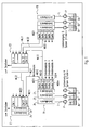
- FIG. 1 Scheme shown can form single or additional color supply systems for special colors, for example in a paint shop for the series coating of vehicle bodies.
- A1, A2 and An denote a number n of color containers for different colors, which are each connected via a pump P to a color distributor FA formed by a valve device. At least the two containers A1 and A2 and in practice only a few further containers are connected to the paint distributor FA, but the total number n per se is arbitrary. The larger the number n, the fewer pigging distances are required.
- each of these central channels can be connected at a pig source station MQ11 to the input of a common line ML11 which leads to the removal point E1 at which the pig target station MZ11 of the line ML11 is located.
- the line ML11 can lead into a central channel Za or into another channel Zb, which can lead to one or more atomizers, which are to be supplied from the containers A1, A2 or An via the common line ML11 common to the respective spot colors ,
- the removal point E1 is similar to the color distributor FA designed as a valve unit and can in particular a usual in supply systems of the type considered connected to Ring effetsmakersssysteme color changer for standard or series colors with the optionally usable, separately flushable central channels Za and Zb upstream of the color distributor FA on the gemgled line ML11 or on the central channels Za or Zb can be connected in parallel.
- the paint distributor FA expediently one or more further pigging lines each with a gemold line such as ML12 and their source and destination stations MQ12, MZ12 connected to connect the color distributor FA with one or more other sampling points such as E2 to which additional atomizers are connected.
- the removal points E1, E2, etc. are located on the manual and / or mechanical, optionally electrostatic, painting zones following one another in the usual way along a painting booth.
- the pig-pig stations of the lines leading to not shown further sampling points are denoted by MQ13, MQ14 and MQ1m, where m can be any number.
- the removal points E1, E2 etc. can be located outside or in the spray booth, for example on a robot arm or on or in the vicinity of other painting machines, while the paint distributor FA is always arranged outside the booth in the example considered here.
- each removal point such as E1 and E2
- further color distributors likewise supplied in each case by individual color supply systems, can be connected in accordance with FA.
- the molten line ML21 is connected to the removal point E1 at the further pig destination station MZ21, whose pig source station MQ21 is in the color distributor FB is located.
- the color distributor FB can be identical to the color distributor FA and thus also contain central channels connected to at least two to n individual color supply systems, each with a container B1, B2, Bn and associated pump P.
- the second color distributor FB is also connected to the removal point E2 via the gemged line ML22 with source and destination stations MQ22 and MZ22.
- the containers B1, B2, Bn may contain different colors than the containers connected to the paint distributor FA, but may u. U. in containers of different color distribution also be the same colors.
- One advantage of the arrangement shown is, inter alia, that, for example, during the supply of the removal point E1 from the color distributor FA already provided a special color for the other color distributor FB and from this even up to the removal point E1 can be pressed, so this for the subsequent coating with a new material without loss of time can be prepared.
- Fig. 2 the valve scheme of one of the color distributors such as FA or FB is shown, which may include a pig feeder station such as MQ11 with, for example, three or two pigs MP and MR as shown, to which the common line ML11 leading to the take-off point E1 is connected.
- the pigs are mechanically positioned by a cylinder unit QZY.
- the mentioned further source stations MQ12 to MQ1m are in Fig. 2 not shown.
- valves for detergent and pulsed air are shown for rinsing the paint distributor.
- the dashed lines represent the e.g. pneumatic control lines of the valves.
- this material is pumped by manual or automatic control with the pump P into the central channel Z1 of the paint distributor FA, which first opens with the valves QFa and QFM open and with the return valve QRFM (FIG. Fig. 2 ) is filled. After this pressing of the existing pump, central channel and return pump circuit, the return valve QRFM is closed, whereupon the color material between the pigs MP and MR through the line ML11 is promoted to the discharge point E1 for pressing the pig track, so that there for delivery the atomizer is ready.
- the paint delivery between pigs possibly with pushout through the rear pig MP is known per se and therefore need not be described in detail.
- the line ML11 and its pig stations can be rinsed separately via the valves provided so that they are immediately available again for repressurization via another central channel Z2 or Zn, even if in the pump circuit of the central channel Z1 still Color is located.
- the pump circuit consisting of pump P, the central channel such as Z1 and the associated feedback is also purged.
- the single supply systems can be operated independently under manual or automatic control. For example, while one system is pressed, the other system may be in the paint or rinse state.
- both the individual supply systems including the central channels such as Z1, Z2 and Zn as well as the pig tracks formed by the lines such as ML11 can each be independently rinsed and filled with material, i. Irrespective of the rinsing or filling of the respective other elements, there are significant advantages, in particular the least possible loss of time during a color or material change.
- the invention is not limited to the paint supply described, but suitable for any other material supply systems with pig tracks.
Landscapes
- Spray Control Apparatus (AREA)
- Application Of Or Painting With Fluid Materials (AREA)
- Coating Apparatus (AREA)
Description
Die Erfindung betrifft ein Verfahren und ein System zur Versorgung von Materialverbrauchern, insbesondere zur Farbversorgung von Beschichtungsvorrichtungen, gemäß dem Oberbegriff der unabhängigen Patentansprüche. Insbesondere handelt es sich um die Serienbeschichtung von Werkstücken wie Fahrzeugkarossen mit ggf. elektrisch leitfähigem Beschichtungsmaterial, bei dem die erste Materialgruppe durch die unterschiedlichen Standard- oder Serienfarben und die zusätzliche Materialgruppe durch verschiedene Sonderfarben gebildet sein können.The invention relates to a method and a system for supplying material consumers, in particular for the ink supply of coating devices, according to the preamble of the independent claims. In particular, it is the series coating of workpieces such as vehicle bodies with possibly electrically conductive coating material, in which the first group of materials can be formed by the different standard or series colors and the additional material group by different special colors.
Für die Serienfarben werden die Zerstäuber der Beschichtungsanlagen für Fahrzeugkarossen bekanntlich aus Ringleitungen gespeist, mit denen sie über Stichleitungen und Farbwechsler verbunden sind, die sich innerhalb der Sprühkabine an oder in der Nähe der Lackierroboter oder sonstigen Beschichtungsmaschinen befinden können. Die Stichleitungen sind in modernen Beschichtungsanlagen zweckmäßig als Molchstrecken ausgebildet (
Der Erfindung liegt die Aufgabe zugrunde, bei Verfahren und Systemen zur Materialversorgung insbesondere der oben beschriebenen Art den für eine gegebene Anzahl von wählbaren zusätzlichen Materialien erforderlichen Aufwand und Platzbedarf der Molchstrecken herabzusetzen und den Nutzungsgrad der vorhandenen gemolchten Leitungen zu erhöhen.The invention has for its object to reduce in processes and systems for material supply in particular of the type described above required for a given number of selectable additional materials overhead and space requirements of the pig lines and to increase the efficiency of existing gemold lines.
Diese Aufgabe wird durch die Merkmale der Patentansprüche gelöst.This object is solved by the features of the claims.
Durch die Erfindung ergibt sich gegenüber früheren Systemen eine wesentliche Reduzierung der Anzahl der benötigten Molchschläuche und Molchstationen jeweils um mindestens 50%. Dementsprechend verringert sich auch der Platzbedarf der Lackversorgungssysteme im Farbmischraum und der Ventilschränke. Dies hat erhebliche Kostenvorteile, zumal sich zusätzliche Vorteile wie Vereinfachung von Layout und Verfahrenssteuerung und kürzere Inbetriebnahmezeiten ergeben. Andererseits können im Vergleich mit früheren Systemen bei annähernd gleichem Aufwand entsprechend viele zusätzliche Einzelversorgungssysteme realisiert werden. Weitere Vorteile sind Minimierung der Druckverluste und der benötigten Farbmengen.As a result of the invention, a significant reduction in the number of pig-tubing hoses and pig-type stations required by at least 50% is achieved in comparison to previous systems. Accordingly, the space required by the paint supply systems in the paint mixing chamber and the valve cabinets is also reduced. This has significant cost advantages, especially since additional benefits such as simplification of layout and process control and shorter commissioning times arise. On the other hand, in comparison with earlier systems with the same amount of effort correspondingly many additional individual supply systems can be realized. Further advantages are minimization of the pressure losses and the required quantities of paint.
Ein typisches Ausführungsbeispiel der Erfindung wird anhand der Zeichnung näher beschrieben. Die Zeichnung zeigt in
- Fig. 1
- eine schematische Darstellung eines Lackversorgungsystems für Sonderfarben; und
- Fig. 2
- das Ventilschema eines Farbverteilers des Systems nach
Fig. 1 .
- Fig. 1
- a schematic representation of a paint supply system for special colors; and
- Fig. 2
- the valve scheme of a color distributor of the system
Fig. 1 ,
Das in
In dem Farbverteiler FA sind die durch je einen der Behälter mit einer zugehörigen Pumpe P gebildeten Einzel- oder Zusatzfarbversorgungssysteme über je eine Eingangsleitung L an je einen Zentralkanal Z1, Z2 bzw. Zn angeschlossen. Über gesteuerte Ventile kann jeder dieser Zentralkanäle an einer Molchquellstation MQ11 an den Eingang einer gemolchten Leitung ML11 angeschlossen werden, die zu der Entnahmestelle E1 führt, an der sich die Molchzielstation MZ11 der Leitung ML11 befindet. In der Entnahmestelle E1 kann die Leitung ML11 in einen Zentralkanal Za oder in einen andern Kanal Zb münden, die zu einem oder mehreren Zerstäubern führen können, die aus den Behältern A1, A2 oder An über die den betreffenden Sonderfarben gemeinsame gemolchte Leitung ML11 versorgt werden sollen. Die Entnahmestelle E1 ist ähnlich wie der Farbverteiler FA als Ventileinheit ausgebildet und kann insbesondere einen bei Versorgungssystemen der betrachteten Art üblichen an Ringleitungsversorgungssysteme angeschlossenen Farbwechsler für Standard- oder Serienfarben mit den wahlweise verwendbaren, separat spülbaren Zentralkanälen Za und Zb enthalten, dem der Farbverteiler FA über die gemolchte Leitung ML11 vorgeschaltet oder an den Zentralkanälen Za oder Zb parallelgeschaltet sein kann.In the color distributor FA, the individual or additional color supply systems formed by one of the containers with an associated pump P are each connected via an input line L to a respective central channel Z1, Z2 or Zn. Via controlled valves, each of these central channels can be connected at a pig source station MQ11 to the input of a common line ML11 which leads to the removal point E1 at which the pig target station MZ11 of the line ML11 is located. In the withdrawal point E1, the line ML11 can lead into a central channel Za or into another channel Zb, which can lead to one or more atomizers, which are to be supplied from the containers A1, A2 or An via the common line ML11 common to the respective spot colors , The removal point E1 is similar to the color distributor FA designed as a valve unit and can in particular a usual in supply systems of the type considered connected to Ringleitungsversorgungssysteme color changer for standard or series colors with the optionally usable, separately flushable central channels Za and Zb upstream of the color distributor FA on the gemgled line ML11 or on the central channels Za or Zb can be connected in parallel.
An die Zentralkanäle Z1, Z2 und Zn des Farbverteilers FA sind zweckmäßig eine oder mehrere weitere Molchstrecken mit je einer gemolchten Leitung wie ML12 und deren Quell- und Zielstationen MQ12, MZ12 angeschlossen, die den Farbverteiler FA mit einer bzw. mehreren weiteren Entnahmestellen wie E2 verbinden, an die weitere Zerstäuber angeschlossen sind. Beispielsweise befinden sich die Entnahmestellen E1, E2 usw. an den längs einer Lackierkabine in üblicher Weise aufeinanderfolgenden manuellen und/oder maschinellen, ggf. elektrostatischen Lackierzonen. Die Molchquellstationen der zu nicht dargestellten weiteren Entnahmestellen führenden Leitungen sind mit MQ13, MQ14 und MQ1m bezeichnet, wobei m eine beliebige Anzahl sein kann. Die Entnahmestellen E1, E2 usw. können sich je nach Anlage außerhalb oder in der Sprühkabine befinden, beispielsweise auf einem Roboterarm oder an oder in der Nähe sonstiger Lackiermaschinen, während der Farbverteiler FA bei dem hier betrachteten Beispiel stets außerhalb der Kabine angeordnet wird.To the central channels Z1, Z2 and Zn of the paint distributor FA expediently one or more further pigging lines each with a gemold line such as ML12 and their source and destination stations MQ12, MZ12 connected to connect the color distributor FA with one or more other sampling points such as E2 to which additional atomizers are connected. For example, the removal points E1, E2, etc., are located on the manual and / or mechanical, optionally electrostatic, painting zones following one another in the usual way along a painting booth. The pig-pig stations of the lines leading to not shown further sampling points are denoted by MQ13, MQ14 and MQ1m, where m can be any number. Depending on the installation, the removal points E1, E2 etc. can be located outside or in the spray booth, for example on a robot arm or on or in the vicinity of other painting machines, while the paint distributor FA is always arranged outside the booth in the example considered here.
Ferner können an jede Entnahmestelle wie E1 und E2 weitere, ebenfalls jeweils von Einzelfarbversorgungssystemen gespeiste Farbverteiler entsprechend FA angeschlossen sein. Bei dem dargestellten Beispiel ist an die Entnahmestelle E1 an der weiteren Molchzielstation MZ21 die gemolchte Leitung ML21 angeschlossen, deren Molchquellstation MQ21 sich in dem Farbverteiler FB befindet. Der Farbverteiler FB kann dem Farbverteiler FA gleichen und somit ebenfalls mit mindestens zwei bis n Einzelfarbversorgungssystemen mit je einem Behälter B1, B2, Bn und zugehöriger Pumpe P verbundene Zentralkanäle enthalten. Darstellungsgemäß ist der zweite Farbverteiler FB über die gemolchte Leitung ML22 mit Quell- und Zielstationen MQ22 und MZ22 auch mit der Entnahmestelle E2 verbunden. Die Behälter B1, B2, Bn können andere Farben enthalten als die an den Farbverteiler FA angeschlossenen Behälter, doch können u. U. in Behältern verschiedener Farbverteiler auch gleiche Farben enthalten sein. Ein Vorteil der dargestellten Anordnung besteht u.a. darin, dass beispielsweise während der Versorgung der Entnahmestelle E1 aus dem Farbverteiler FA bereits eine Sonderfarbe für den anderen Farbverteiler FB bereitgestellt und hieraus auch schon bis zu der Entnahmestelle E1 angedrückt werden kann, diese also für die anschließende Beschichtung mit einem neuen Material ohne Zeitverlust vorbereitet werden kann.Furthermore, at each removal point, such as E1 and E2, further color distributors, likewise supplied in each case by individual color supply systems, can be connected in accordance with FA. In the example shown, the molten line ML21 is connected to the removal point E1 at the further pig destination station MZ21, whose pig source station MQ21 is in the color distributor FB is located. The color distributor FB can be identical to the color distributor FA and thus also contain central channels connected to at least two to n individual color supply systems, each with a container B1, B2, Bn and associated pump P. As can be seen, the second color distributor FB is also connected to the removal point E2 via the gemged line ML22 with source and destination stations MQ22 and MZ22. The containers B1, B2, Bn may contain different colors than the containers connected to the paint distributor FA, but may u. U. in containers of different color distribution also be the same colors. One advantage of the arrangement shown is, inter alia, that, for example, during the supply of the removal point E1 from the color distributor FA already provided a special color for the other color distributor FB and from this even up to the removal point E1 can be pressed, so this for the subsequent coating with a new material without loss of time can be prepared.
In
Bei QV und QPL sind weitere Ventile für Spülmittel und Pulsluft zum Spülen des Farbverteilers dargestellt. Die gestrichelten Linien stellen die z.B. pneumatischen Steuerleitungen der Ventile dar.For QV and QPL, additional valves for detergent and pulsed air are shown for rinsing the paint distributor. The dashed lines represent the e.g. pneumatic control lines of the valves.
Wenn im Betrieb beispielsweise mit der Sonderfarbe aus dem Behälter A1 lackiert werden soll, wird dieses Material durch manuelle oder automatische Steuerung mit der Pumpe P in den Zentralkanal Z1 des Farbverteilers FA gepumpt, der zunächst bei geöffneten Ventilen QFa und QFM und bei geöffnetem Rückführventil QRFM (
Sofort nach dem Zurückmolchen können die Leitung ML11 und ihre Molchstationen über die dafür vorgesehenen Ventile separat gespült werden, so dass sie sofort wieder für das erneute Andrücken über einen anderen Zentralkanal Z2 oder Zn zur Verfügung stehen, auch wenn sich in dem Pumpenkreis des Zentralkanals Z1 noch Farbe befindet. Separat wird auch der aus der Pumpe P, dem Zentralkanal wie Z1 und der zugehörigen Rückführung bestehende Pumpenkreis gespült. Die Einzelversorgungssysteme können unter manueller oder automatischer Steuerung unabhängig voneinander betrieben werden. Während also z.B. das eine System angedrückt wird, kann sich das jeweils andere System im Lackier- oder Spülzustand befinden.Immediately after the pig back, the line ML11 and its pig stations can be rinsed separately via the valves provided so that they are immediately available again for repressurization via another central channel Z2 or Zn, even if in the pump circuit of the central channel Z1 still Color is located. Separately, the pump circuit consisting of pump P, the central channel such as Z1 and the associated feedback is also purged. The single supply systems can be operated independently under manual or automatic control. For example, while one system is pressed, the other system may be in the paint or rinse state.
Dadurch, dass sowohl die Einzelversorgungssysteme einschließlich der Zentralkanäle wie Z1, Z2 und Zn als auch die durch die Leitungen wie ML11 gebildeten Molchstrecken jeweils autark gespült und mit Material befüllt (angedrückt) werden können, d.h. unabhängig von dem Spülen bzw. Befüllen der jeweils anderen Elemente, ergeben sich wesentliche Vorteile wie insbesondere geringstmögliche Zeitverluste bei einem Farboder Materialwechsel.The fact that both the individual supply systems including the central channels such as Z1, Z2 and Zn as well as the pig tracks formed by the lines such as ML11 can each be independently rinsed and filled with material, i. Irrespective of the rinsing or filling of the respective other elements, there are significant advantages, in particular the least possible loss of time during a color or material change.
Die Erfindung ist nicht auf die beschriebene Lackversorgung beschränkt, sondern für beliebige sonstige Materialversorgungssysteme mit Molchstrecken geeignet.The invention is not limited to the paint supply described, but suitable for any other material supply systems with pig tracks.
Claims (14)
- A method for feeding different materials to material consumers through pigged paths, particularly for supplying paint to coating devices for coating workpieces with materials of different colours, in which are fed selectively material from a first group of materials
or at least two different materials from an additional second material group from single supply systems (A1, A2, An) through a pigged line arrangement (ML11)
to a discharge point (E1) of the consumers,
characterised in that the at least two different materials from their single supply systems (A1, A2, An) are fed to a valve device (FA), controlled to select the desired material, from where it is fed through the common pigged line (ML11) to the discharge point (E1). - The method in accordance with claim 1, characterised in that the single supply systems (A1, A2, An; P; Z1, Z2; Zn) and the pigged line (ML11) are autonomously flushed and filled with material by valve control.
- The method in accordance with claim 1 or 2, characterised in that the material is pumped directly into the valve device (FA) by pumps (P) connected to the material vessels (A1, A2, An) of the additional single supply systems.
- The method in accordance with one of the preceding claims, characterised in that the material from the additional single supply systems is fed from the valve device (FA) through a dedicated pigged line (ML11, ML12) to a plurality of discharge points (E1, E2).
- The method in accordance with one of the preceding claims, characterised in that each discharge point (E1) is supplied through one pigged line (ML11, ML21) by at least two valve devices (FA, FB), each connected to single supply systems (A1, A2, An; B1, B2, Bn).
- A system for feeding different materials to material consumers through pigged paths, particularly for supplying paint to coating devices for coating workpieces with materials of different colours, in which are fed selectively material from a first group of materials
or at least two different materials from an additional second material group from single supply systems (A1, A2, An) through a pigged line arrangement (ML11)
to a discharge point (E1) of the consumers,
characterised in that a valve device (FA) is located between the additional single supply systems (A1, A2, An) and the pigged line (ML11) by which the additional single supply systems (A1, A2, An) can be connected selectively to their common pigged line (ML11). - The system in accordance with claim 6, characterised in that the valve device (FA) contains two or more channels (Z1, Z2, Zn) connected to one of the single supply systems respectively, with which the pigged line (ML11) is selectively connectable through controlled first valves (QFa, QFb, QFc), and in that the pigged line (ML11) and the channels (Z1, Z2, Zn) can be flushed and filled with material independently of each other by the valve control.
- The system in accordance with claim 6 or 7, characterised in that the valve device (FA) is located outside a spray cabin, in which the discharge point (E1) and/or an application device connected to the discharge point is located, in the vicinity of the material vessels (A1, A2, An) of the additional single supply systems, and a pump (P) is connected between the material vessels (A1, A2, An) and the valve device (FA).
- The system in accordance with one of claims 6 to 8, characterised in that the valve device (FA) is embodied as a material distributor, from which one pigged line (ML11, ML12) respectively leads to several discharge points (E1, E2).
- The system in accordance with one of claims 6 to 9, characterised in that each discharge point (E1, E2) is connected to at least two valve units (FA, FB), each connected to additional single supply systems (A1, A2, An; B1, B2, Bn).
- The system in accordance with one of claims 6 to 10, characterised in that the valve device (FA, FB) contains at least one pig source station (MQ11) for the connected pigged line (ML11).
- The system in accordance with one of claims 6 to 11, characterised in that a colour-changer valve arrangement (Za, Zb) connected to ring circulation lines for the first group of materials is provided at or in the discharge point (E1, E2), and that the discharge point contains controlled valves through which the or each of the connected consumers is supplied selectively with materials from the first or second group.
- The system in accordance with one of claims 6 to 12, characterised in that the valve device (FA) contains controlled valves (QFa, QFb, QFc, QFM) by which channels (Z1, Z2, Zn) of the valve device (FA) fed from the connected material vessels (A1, A2, An) can be connected selectively to each of several pigged lines (ML11, ML12) connected to the valve device (FA).
- Valve device for a system in accordance with one of claims 6 to 13, characterised in that it contains controlled valves (QFa, QFb, QFc, QFM) by which channels (Z1, Z2, Zn) also contained in the valve device can be selectively connected to the outlet channel (ML11) of one or more pig stations (MQ11) contained in the valve device.
Priority Applications (1)
| Application Number | Priority Date | Filing Date | Title |
|---|---|---|---|
| PL04023410T PL1522348T3 (en) | 2003-10-07 | 2004-10-01 | Method and system for feeding material to a consumer device over a pigged path |
Applications Claiming Priority (2)
| Application Number | Priority Date | Filing Date | Title |
|---|---|---|---|
| DE10346601A DE10346601A1 (en) | 2003-10-07 | 2003-10-07 | Method and system for supplying material consumers via pigging lines |
| DE10346601 | 2003-10-07 |
Publications (3)
| Publication Number | Publication Date |
|---|---|
| EP1522348A2 EP1522348A2 (en) | 2005-04-13 |
| EP1522348A3 EP1522348A3 (en) | 2008-01-23 |
| EP1522348B1 true EP1522348B1 (en) | 2009-07-22 |
Family
ID=34306312
Family Applications (1)
| Application Number | Title | Priority Date | Filing Date |
|---|---|---|---|
| EP04023410A Active EP1522348B1 (en) | 2003-10-07 | 2004-10-01 | Method and system for feeding material to a consumer device over a pigged path |
Country Status (3)
| Country | Link |
|---|---|
| EP (1) | EP1522348B1 (en) |
| DE (2) | DE10346601A1 (en) |
| PL (1) | PL1522348T3 (en) |
Families Citing this family (2)
| Publication number | Priority date | Publication date | Assignee | Title |
|---|---|---|---|---|
| BRPI0910228B1 (en) | 2008-03-20 | 2019-11-26 | Duerr Systems Gmbh | painting robot |
| DE102023102825A1 (en) | 2023-02-06 | 2024-08-08 | Dürr Systems Ag | Coating agent supply system and associated operating procedure |
Family Cites Families (10)
| Publication number | Priority date | Publication date | Assignee | Title |
|---|---|---|---|---|
| DE19632325A1 (en) | 1996-08-10 | 1998-02-12 | Herberts Gmbh | Paint supply unit for paint-spray in car production line |
| DE19742588B4 (en) * | 1997-09-26 | 2009-02-19 | Dürr Systems GmbH | Method for serial coating of workpieces |
| DE19830029A1 (en) * | 1998-07-04 | 2000-01-05 | Audi Ag | Painting rig for vehicle bodywork |
| DE19937474C2 (en) * | 1999-08-07 | 2001-08-02 | Eisenmann Lacktechnik Kg | Painting device with a gun unit, a color changing device and a piggable connecting device |
| DE10006310A1 (en) * | 2000-02-12 | 2001-08-16 | Lactec Gmbh | Coating method and apparatus |
| DE10033987A1 (en) * | 2000-07-13 | 2002-01-24 | Duerr Systems Gmbh | Process for supplying a coating member for the electrostatic series coating of workpieces and supply system therefor |
| DE10059041C2 (en) * | 2000-11-28 | 2002-11-14 | Lactec Ges Fuer Moderne Lackte | Method and device for conveying electrically conductive paints between different voltage potentials |
| DE10120077B4 (en) * | 2001-04-24 | 2006-07-27 | Dürr Systems GmbH | Coating system for automated coating technology |
| DE10131562A1 (en) | 2001-06-29 | 2003-01-16 | Duerr Systems Gmbh | Method and system for supplying a coating device |
| DE10157966A1 (en) | 2001-11-27 | 2003-06-05 | Duerr Systems Gmbh | Method and supply system for the metered supply of material to a coating device |
-
2003
- 2003-10-07 DE DE10346601A patent/DE10346601A1/en not_active Ceased
-
2004
- 2004-10-01 PL PL04023410T patent/PL1522348T3/en unknown
- 2004-10-01 EP EP04023410A patent/EP1522348B1/en active Active
- 2004-10-01 DE DE502004009778T patent/DE502004009778D1/en active Active
Also Published As
| Publication number | Publication date |
|---|---|
| DE10346601A1 (en) | 2005-05-12 |
| PL1522348T3 (en) | 2009-12-31 |
| EP1522348A2 (en) | 2005-04-13 |
| DE502004009778D1 (en) | 2009-09-03 |
| EP1522348A3 (en) | 2008-01-23 |
Similar Documents
| Publication | Publication Date | Title |
|---|---|---|
| EP0292778B1 (en) | Process and installation for electrostatic coating with a conductive coating product | |
| EP1172152B1 (en) | Paint supply system with piggable supply lines for an electrostatic coating device | |
| EP2853312B1 (en) | ICC metering | |
| EP2076336B1 (en) | Fluid supply device for spraying system | |
| DE69332680T2 (en) | Process for dispensing conductive coating materials | |
| EP1245295B1 (en) | Colour changing system for a coating device | |
| EP1270087B1 (en) | Powder coating installation | |
| DE3014221A1 (en) | METHOD AND DEVICE FOR ELECTROSTATIC SPRAYING | |
| EP1314483B1 (en) | Method and system for metered delivery of coating material to a coating apparatus | |
| DE69827611T2 (en) | COATING DEVICE WITH A TURNING SPRAY HEAD | |
| DE3717929C2 (en) | ||
| EP1344572B1 (en) | Painting installation for coating pieces with a liquid material | |
| DE3927880A1 (en) | Coating system using different paints - has different paint tanks selectively connected to spray device | |
| EP1095707B1 (en) | Colour change valve assembly and method for flushing a colour changer | |
| DE10131562A1 (en) | Method and system for supplying a coating device | |
| EP1522348B1 (en) | Method and system for feeding material to a consumer device over a pigged path | |
| DE102008037035B4 (en) | Valve arrangement of a painting robot | |
| EP0541745B1 (en) | Spray coating device | |
| EP1124644A1 (en) | Method and arrangement for transporting electroconductive lacquer | |
| EP1124645A1 (en) | Method and arrangement for the transport of electrically conductive paint | |
| DE10342643A1 (en) | Method for operating a media conveyor system | |
| DE20122759U1 (en) | Color change system for unit for series coating of work pieces e.g. vehicle chassis, has drive device, with which connection valve and supply valve are able to couple together and separate from each other in given direction of movement | |
| EP1010469B1 (en) | Process and system for supplying paint to an electrostatic coating installation | |
| EP0842706B1 (en) | Coating installation and method for controlling the flow of coating material in this installation | |
| EP1369182B1 (en) | Painting installation |
Legal Events
| Date | Code | Title | Description |
|---|---|---|---|
| PUAI | Public reference made under article 153(3) epc to a published international application that has entered the european phase |
Free format text: ORIGINAL CODE: 0009012 |
|
| AK | Designated contracting states |
Kind code of ref document: A2 Designated state(s): AT BE BG CH CY CZ DE DK EE ES FI FR GB GR HU IE IT LI LU MC NL PL PT RO SE SI SK TR |
|
| AX | Request for extension of the european patent |
Extension state: AL HR LT LV MK |
|
| PUAL | Search report despatched |
Free format text: ORIGINAL CODE: 0009013 |
|
| AK | Designated contracting states |
Kind code of ref document: A3 Designated state(s): AT BE BG CH CY CZ DE DK EE ES FI FR GB GR HU IE IT LI LU MC NL PL PT RO SE SI SK TR |
|
| AX | Request for extension of the european patent |
Extension state: AL HR LT LV MK |
|
| 17P | Request for examination filed |
Effective date: 20080627 |
|
| AKX | Designation fees paid |
Designated state(s): AT BE BG CH CY CZ DE DK EE ES FI FR GB GR HU IE IT LI LU MC NL PL PT RO SE SI SK TR |
|
| 17Q | First examination report despatched |
Effective date: 20081114 |
|
| GRAP | Despatch of communication of intention to grant a patent |
Free format text: ORIGINAL CODE: EPIDOSNIGR1 |
|
| GRAS | Grant fee paid |
Free format text: ORIGINAL CODE: EPIDOSNIGR3 |
|
| GRAA | (expected) grant |
Free format text: ORIGINAL CODE: 0009210 |
|
| AK | Designated contracting states |
Kind code of ref document: B1 Designated state(s): AT BE BG CH CY CZ DE DK EE ES FI FR GB GR HU IE IT LI LU MC NL PL PT RO SE SI SK TR |
|
| REG | Reference to a national code |
Ref country code: GB Ref legal event code: FG4D Free format text: NOT ENGLISH |
|
| REG | Reference to a national code |
Ref country code: CH Ref legal event code: EP |
|
| REG | Reference to a national code |
Ref country code: IE Ref legal event code: FG4D |
|
| REF | Corresponds to: |
Ref document number: 502004009778 Country of ref document: DE Date of ref document: 20090903 Kind code of ref document: P |
|
| REG | Reference to a national code |
Ref country code: SE Ref legal event code: TRGR |
|
| REG | Reference to a national code |
Ref country code: PL Ref legal event code: T3 |
|
| RAP2 | Party data changed (patent owner data changed or rights of a patent transferred) |
Owner name: DUERR SYSTEMS GMBH |
|
| PG25 | Lapsed in a contracting state [announced via postgrant information from national office to epo] |
Ref country code: FI Free format text: LAPSE BECAUSE OF FAILURE TO SUBMIT A TRANSLATION OF THE DESCRIPTION OR TO PAY THE FEE WITHIN THE PRESCRIBED TIME-LIMIT Effective date: 20090722 Ref country code: ES Free format text: LAPSE BECAUSE OF FAILURE TO SUBMIT A TRANSLATION OF THE DESCRIPTION OR TO PAY THE FEE WITHIN THE PRESCRIBED TIME-LIMIT Effective date: 20091102 |
|
| PG25 | Lapsed in a contracting state [announced via postgrant information from national office to epo] |
Ref country code: SI Free format text: LAPSE BECAUSE OF FAILURE TO SUBMIT A TRANSLATION OF THE DESCRIPTION OR TO PAY THE FEE WITHIN THE PRESCRIBED TIME-LIMIT Effective date: 20090722 |
|
| NLT2 | Nl: modifications (of names), taken from the european patent patent bulletin |
Owner name: DUERR SYSTEMS GMBH Effective date: 20100120 |
|
| REG | Reference to a national code |
Ref country code: IE Ref legal event code: FD4D |
|
| PG25 | Lapsed in a contracting state [announced via postgrant information from national office to epo] |
Ref country code: BG Free format text: LAPSE BECAUSE OF FAILURE TO SUBMIT A TRANSLATION OF THE DESCRIPTION OR TO PAY THE FEE WITHIN THE PRESCRIBED TIME-LIMIT Effective date: 20091022 Ref country code: PT Free format text: LAPSE BECAUSE OF FAILURE TO SUBMIT A TRANSLATION OF THE DESCRIPTION OR TO PAY THE FEE WITHIN THE PRESCRIBED TIME-LIMIT Effective date: 20091122 |
|
| PG25 | Lapsed in a contracting state [announced via postgrant information from national office to epo] |
Ref country code: DK Free format text: LAPSE BECAUSE OF FAILURE TO SUBMIT A TRANSLATION OF THE DESCRIPTION OR TO PAY THE FEE WITHIN THE PRESCRIBED TIME-LIMIT Effective date: 20090722 Ref country code: RO Free format text: LAPSE BECAUSE OF FAILURE TO SUBMIT A TRANSLATION OF THE DESCRIPTION OR TO PAY THE FEE WITHIN THE PRESCRIBED TIME-LIMIT Effective date: 20090722 Ref country code: IE Free format text: LAPSE BECAUSE OF FAILURE TO SUBMIT A TRANSLATION OF THE DESCRIPTION OR TO PAY THE FEE WITHIN THE PRESCRIBED TIME-LIMIT Effective date: 20090722 Ref country code: EE Free format text: LAPSE BECAUSE OF FAILURE TO SUBMIT A TRANSLATION OF THE DESCRIPTION OR TO PAY THE FEE WITHIN THE PRESCRIBED TIME-LIMIT Effective date: 20090722 |
|
| PLBE | No opposition filed within time limit |
Free format text: ORIGINAL CODE: 0009261 |
|
| REG | Reference to a national code |
Ref country code: HU Ref legal event code: AG4A Ref document number: E007063 Country of ref document: HU |
|
| STAA | Information on the status of an ep patent application or granted ep patent |
Free format text: STATUS: NO OPPOSITION FILED WITHIN TIME LIMIT |
|
| PG25 | Lapsed in a contracting state [announced via postgrant information from national office to epo] |
Ref country code: MC Free format text: LAPSE BECAUSE OF NON-PAYMENT OF DUE FEES Effective date: 20091031 Ref country code: SK Free format text: LAPSE BECAUSE OF FAILURE TO SUBMIT A TRANSLATION OF THE DESCRIPTION OR TO PAY THE FEE WITHIN THE PRESCRIBED TIME-LIMIT Effective date: 20090722 |
|
| REG | Reference to a national code |
Ref country code: CH Ref legal event code: PL |
|
| 26N | No opposition filed |
Effective date: 20100423 |
|
| PG25 | Lapsed in a contracting state [announced via postgrant information from national office to epo] |
Ref country code: LI Free format text: LAPSE BECAUSE OF NON-PAYMENT OF DUE FEES Effective date: 20091031 Ref country code: CH Free format text: LAPSE BECAUSE OF NON-PAYMENT OF DUE FEES Effective date: 20091031 Ref country code: GR Free format text: LAPSE BECAUSE OF FAILURE TO SUBMIT A TRANSLATION OF THE DESCRIPTION OR TO PAY THE FEE WITHIN THE PRESCRIBED TIME-LIMIT Effective date: 20091023 |
|
| PG25 | Lapsed in a contracting state [announced via postgrant information from national office to epo] |
Ref country code: GB Free format text: LAPSE BECAUSE OF NON-PAYMENT OF DUE FEES Effective date: 20091022 |
|
| PG25 | Lapsed in a contracting state [announced via postgrant information from national office to epo] |
Ref country code: AT Free format text: LAPSE BECAUSE OF NON-PAYMENT OF DUE FEES Effective date: 20091001 |
|
| PG25 | Lapsed in a contracting state [announced via postgrant information from national office to epo] |
Ref country code: LU Free format text: LAPSE BECAUSE OF NON-PAYMENT OF DUE FEES Effective date: 20091001 |
|
| PG25 | Lapsed in a contracting state [announced via postgrant information from national office to epo] |
Ref country code: CY Free format text: LAPSE BECAUSE OF FAILURE TO SUBMIT A TRANSLATION OF THE DESCRIPTION OR TO PAY THE FEE WITHIN THE PRESCRIBED TIME-LIMIT Effective date: 20090722 |
|
| REG | Reference to a national code |
Ref country code: DE Ref legal event code: R008 Ref document number: 502004009778 Country of ref document: DE |
|
| REG | Reference to a national code |
Ref country code: DE Ref legal event code: R039 Ref document number: 502004009778 Country of ref document: DE Effective date: 20140522 |
|
| REG | Reference to a national code |
Ref country code: DE Ref legal event code: R097 Ref document number: 502004009778 Country of ref document: DE Ref country code: DE Ref legal event code: R040 Ref document number: 502004009778 Country of ref document: DE |
|
| REG | Reference to a national code |
Ref country code: FR Ref legal event code: PLFP Year of fee payment: 12 |
|
| REG | Reference to a national code |
Ref country code: DE Ref legal event code: R082 Ref document number: 502004009778 Country of ref document: DE Representative=s name: V. BEZOLD & PARTNER PATENTANWAELTE - PARTG MBB, DE Ref country code: DE Ref legal event code: R081 Ref document number: 502004009778 Country of ref document: DE Owner name: DUERR SYSTEMS AG, DE Free format text: FORMER OWNER: DUERR SYSTEMS GMBH, 74321 BIETIGHEIM-BISSINGEN, DE |
|
| REG | Reference to a national code |
Ref country code: FR Ref legal event code: PLFP Year of fee payment: 13 |
|
| REG | Reference to a national code |
Ref country code: DE Ref legal event code: R082 Ref document number: 502004009778 Country of ref document: DE Representative=s name: V. BEZOLD & PARTNER PATENTANWAELTE - PARTG MBB, DE Ref country code: DE Ref legal event code: R081 Ref document number: 502004009778 Country of ref document: DE Owner name: DUERR SYSTEMS AG, DE Free format text: FORMER OWNER: DUERR SYSTEMS AG, 74321 BIETIGHEIM-BISSINGEN, DE |
|
| REG | Reference to a national code |
Ref country code: FR Ref legal event code: PLFP Year of fee payment: 14 |
|
| REG | Reference to a national code |
Ref country code: FR Ref legal event code: PLFP Year of fee payment: 15 |
|
| P01 | Opt-out of the competence of the unified patent court (upc) registered |
Effective date: 20230512 |
|
| PGFP | Annual fee paid to national office [announced via postgrant information from national office to epo] |
Ref country code: TR Payment date: 20230929 Year of fee payment: 20 Ref country code: CZ Payment date: 20230922 Year of fee payment: 20 |
|
| PGFP | Annual fee paid to national office [announced via postgrant information from national office to epo] |
Ref country code: PL Payment date: 20230922 Year of fee payment: 20 Ref country code: NL Payment date: 20231019 Year of fee payment: 20 |
|
| PGFP | Annual fee paid to national office [announced via postgrant information from national office to epo] |
Ref country code: SE Payment date: 20231019 Year of fee payment: 20 Ref country code: IT Payment date: 20231026 Year of fee payment: 20 Ref country code: HU Payment date: 20231024 Year of fee payment: 20 Ref country code: FR Payment date: 20231023 Year of fee payment: 20 Ref country code: DE Payment date: 20231020 Year of fee payment: 20 |
|
| PGFP | Annual fee paid to national office [announced via postgrant information from national office to epo] |
Ref country code: BE Payment date: 20231019 Year of fee payment: 20 |