EP0842706B1 - Installation de revêtement et procédé de commande de l'écoulement du matériau de revêtement dans cette installation - Google Patents
Installation de revêtement et procédé de commande de l'écoulement du matériau de revêtement dans cette installation Download PDFInfo
- Publication number
- EP0842706B1 EP0842706B1 EP97119659A EP97119659A EP0842706B1 EP 0842706 B1 EP0842706 B1 EP 0842706B1 EP 97119659 A EP97119659 A EP 97119659A EP 97119659 A EP97119659 A EP 97119659A EP 0842706 B1 EP0842706 B1 EP 0842706B1
- Authority
- EP
- European Patent Office
- Prior art keywords
- coating
- ring main
- downstream
- shutoff
- point
- Prior art date
- Legal status (The legal status is an assumption and is not a legal conclusion. Google has not performed a legal analysis and makes no representation as to the accuracy of the status listed.)
- Expired - Lifetime
Links
Images

Classifications
-
- B—PERFORMING OPERATIONS; TRANSPORTING
- B05—SPRAYING OR ATOMISING IN GENERAL; APPLYING FLUENT MATERIALS TO SURFACES, IN GENERAL
- B05B—SPRAYING APPARATUS; ATOMISING APPARATUS; NOZZLES
- B05B9/00—Spraying apparatus for discharge of liquids or other fluent material, without essentially mixing with gas or vapour
- B05B9/03—Spraying apparatus for discharge of liquids or other fluent material, without essentially mixing with gas or vapour characterised by means for supplying liquid or other fluent material
- B05B9/035—Spraying apparatus for discharge of liquids or other fluent material, without essentially mixing with gas or vapour characterised by means for supplying liquid or other fluent material to several spraying apparatus
Definitions
- the invention relates to a method for automatic control the material flow in a coating system Series coating of workpieces and a corresponding one Coating line according to the generic term of the independent Claims.
- a typical application example for this is the automatic one Paint supply for painting systems for serial coating of Workpieces such as Motor vehicle bodies, which as Loop color circulation systems are designed to be as possible largely the deposition of the paint during coating breaks to avoid.
- the well-known cabin ring line systems consist of a feed line from each color Paint container and the feed pump in the paint mixing room Paint booth and a return line from the paint booth via an adjustable return control valve back to Paint container. With the pressure difference between the outlet the feed pump and the adjustable return control valve a continuous color circulation is created.
- Paint booths are usually multiple atomizers or other coating devices distributed for the several Ink acceptance or connection points (so-called ink niches) different locations along the cabin are provided.
- the automatic coating machines such as.
- the invention has for its object a method and to specify a coating system that stops the Coating material easier and with less construction and Avoid energy expenditure than before.
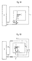
- FIG. 1A shows a known ink supply system with a Ring line 1, coming from a supply system 2 and circulating coating material flowing back there.
- the supply system can e.g. in a color mixing room are located.
- a branch line 3 branches off from the ring line 1, via a control valve to the coating device 4 leads.
- FIG. 1B shows the alternative possibility mentioned above with a main line 6 coming from the supply system 2, from the branches a feed line 7, which over the illustrated Valve arrangement on the one hand with the coating device 4 and on the other hand with one back into the supply system 2 leading return line 8 is connectable. Over in the Main line 6 and the return line 8 switched pre-pressure or. Return regulator can provide the required operating pressure can be set.
- a single complete ring line 10 is present, which is fed by a supply system 2 as before, and from the at the connection point 11 a feed line 12 to the Valve arrangement 13 of the coating device 14 leads.
- the feed line 12 is here for example via a valve of the arrangement 13 with a separate return line 15 connected to or downstream behind a shut-off point of the ring line 10 in this ends.
- the shut-off point is a downstream of the Junction 11 switched into the ring line automatically controlled shut-off valve 16 is formed.
- the shut-off valve 16 is open, so that the coating material continuously through the Ring line 10 from and back to the supply system 2 circulates and the part of the material required for spraying due to the working pressure in the ring line through the valve arrangement 13 to the coating device 14 flows.
- valve 16 In the coating breaks, however, the ring line on the Blocking point blocked by valve 16. At the same time when the coating device 14 is blocked, the path from the Feed line 12 to the return line 15 and from this in the unlocked part of the ring line 10 behind the Valve 16 released so that the coating material constantly through the feed line 12 and now also through the Return line 15 flows and can not settle.
- the Valve 16 is actuated by a control signal.
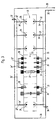
- FIG. 3 shows a typical coating system for Series coating of motor vehicle bodies shown.
- she contains (per color) a ring line 20 in the form of a one Paint booth 21 pipeline routed to a (here supply system (not shown) is connected.
- the Paint booth contains in the example shown in the indicated by the arrow 23 conveying direction of the bodies
- Six in a row consisting of hand spray guns Coating devices 25, six electrostatically working Coating devices 26 (e.g. rotary atomizers), further coating devices 27 on a roof machine, three consisting of automatic air atomizers Devices 28 and two other manually operated Coating devices 29.
- the Coating devices other than devices 27 and one device 28, as usual, each on the two Cabin sides distributed.
- the automatic motion machines moving coating devices are directly on the Cabin wall arranged.
- the respective color changers are located in the immediate vicinity of the coating devices, for example in the machine arm of the motion machines or in "Roof bars" of the roof machine to prevent paint and solvent losses reduced to a minimum when changing colors.
- Each of the branches branched from the main circulation or ring line 20 Feed lines 32 is on the (not shown) Valve arrangement of the coating arrangement to which it leads, for example via an automatically controlled valve Valve arrangement connected to a line 34, which in a separate return line 35 common to all lines 34 leads, which in turn on the shutoff valve 36 downstream opens into the ring line 20 behind the shut-off point.
- the outgoing lines 32 ' Valves and lines 34 'to one of these lines 34' shared separate return line 35 'connected to the shut-off valve 37 downstream behind this shut-off point opens into the ring line 20.
- coating devices 26 and 28 can lead to several atomizers feed lines fed by a common feed line 32 or 32 ' and in parallel to that coming from these atomizers Lines 34 and 34 'via a common line be connected to the return line 35 or 35 '.
- valve arrangements mentioned Coating devices can include the color changer or be connected to a color changer with which the relevant coating device selectively over their Supply and return lines with the ring line for the desired color can be connected.
- the supply and return lines can be advantageous e.g. consist of relatively simple hoses that are easy are controllable and not in contrast to the ring line 20 lead the entire cabin around.
- the check valves 36 and 37 can simultaneously and can be controlled in the same direction by a common control signal, however there are other control options. You can be designed as a switchable multi-way valve that in your one switching state releases the ring line 20 and in the other Switching status blocks the ring line and at the same time a way for the return line 35 directly connected to the valve or 35 'in the respective unlocked part of the Ring line opens.
- shut-off points in the ring line can also be provided.
- the shut-off valves of the Ring line not during the entire break times of the Coating closed and the paths of the return lines be open, e.g. not if the coating company is interrupted for a long time.
Landscapes
- Spray Control Apparatus (AREA)
- Nozzles (AREA)
- Application Of Or Painting With Fluid Materials (AREA)
Claims (9)
- Procédé pour commander automatiquement l'écoulement de la matière dans une installation d'application d'un revêtement pour recouvrir en série des pièces, dans laquelle la matière du revêtement circule, pendant l'application du revêtement, à travers une conduite annulaire (10, 20) depuis laquelle elle est acheminée vers un dispositif d'application de revêtement (14, 25-29), en un ou plusieurs points de raccordement, par une conduite aller (12, 32, 32') respective, caractérisé en ce qu'au moins pendant une partie des pauses d'application du revêtement, la conduite annulaire (10, 20) est fermée en aval du point ou des points de raccordement, et la matière du revêtement est renvoyée dans la conduite annulaire (10, 20), depuis la conduite aller (12, 32, 32') respective par une conduite de retour (15, 35, 35') séparée, derrière le point de fermeture.
- Procédé selon la revendication 1, caractérisé en ce que dans les pauses d'application du revêtement, la conduite annulaire (20) est fermée en un deuxième point (37), situé en aval du point de fermeture (36), et la matière du revêtement qui provient de la conduite de retour (35) séparée, est conduite, en aval du premier point de fermeture (36), dans des conduites aller (32') menant, entre les deux points de fermeture (36, 37), depuis la conduite annulaire (20) jusqu'à d'autres dispositifs d'application du revêtement, et, de là, est renvoyée dans la conduite annulaire (20), derrière le deuxième point de fermeture (37).
- Installation d'application d'un revêtement pour recouvrir en série des pièces, comportant une conduite annulaire (1à, 20) raccordée à un système d'alimentation (2), et au moins deux conduites aller (12, 32, 32') menant de la conduite annulaire, en un point de raccordement respectif, à un dispositif d'application de revêtement (14, 25-29), caractérisée en ce que dans la conduite annulaire (10, 20), en un point se trouvant en aval des points de raccordement, est montée une vanne d'arrêt (16, 36, 37) commandée automatiquement, pour fermer la conduite annulaire (10, 20), et en ce que les conduites aller (12, 32, 32') sont raccordées à une conduite retour (15, 35, 35') séparée qui leur est commune et qui mène dans la conduite annulaire (10, 20), en aval du point de fermeture (16, 36, 37).
- Installation d'application d'un revêtement selon la revendication 3, caractérisée en ce que la conduite annulaire (20) contient au moins deux vannes d'arrêt (36, 37), en ce qu'au moins deux conduites aller (32) qui, en amont du premier point de fermeture, mènent de la conduite annulaire (20) respectivement à un ou plusieurs dispositifs (25 à 29) d'application d'un revêtement, sont raccordées à une conduite retour (35) commune qui, en aval du premier point de fermeture (36), mène dans la conduite annulaire (20), et en ce qu'entre les deux points de fermeture (36, 37) d'autres conduites aller (32'), qui mènent chacune de la conduite annulaire (20) à des dispositifs d'application d'un revêtement, sont raccordées à une deuxième conduite retour (35') séparée qui leur est commune et qui mène dans la conduite annulaire (20), en aval du deuxième point de fermeture (37).
- Installation d'application d'un revêtement selon la revendication 4, caractérisée en ce que les deux vannes d'arrêt (36, 37) peuvent être commandée simultanément et dans le même sens.
- Installation d'application d'un revêtement selon l'une des revendications 3 à 5, caractérisée en ce que devant les dispositifs (25 à 29) d'application d'un revêtement sont montés des ensembles de vannes au moyen desquels on peut commander la liaison entre les conduites aller (32, 32') et les conduites retour (35, 35').
- Installation d'application d'un revêtement selon l'une des revendications 3 à 6, caractérisée en ce que pour chaque couleur à choisir pour le revêtement sont prévues une conduite annulaire et des conduites aller et retour correspondantes, et en ce que les ensembles de vannes des dispositifs d'application d'un revêtement sont réalisés en tant que parties d'un changeur de couleur ou sont reliés à un changeur de couleur par lequel les dispositifs d'application d'un revêtement peuvent être reliés, de manière sélective, à toutes les conduites annulaires.
- Installation d'application d'un revêtement selon l'une des revendications 3 à 7, caractérisée en ce que la section de la conduite retour (35, 35') séparée augmente par paliers dans le sens d'écoulement.
- Installation d'application d'un revêtement selon l'une des revendications 3 à 8, caractérisée en ce que la vanne d'arrêt (36, 37) est réalisée en tant que vanne commutable à plusieurs voies qui, dans l'une de ses positions de commutation, ouvre la conduite annulaire (20) dans le sens de circulation, tandis que dans sa deuxième position de commutation, elle ferme la conduite annulaire et conduit la matière de revêtement depuis la conduite retour (35, 35') séparée dans la partie non fermée de la conduite annulaire (20).
Applications Claiming Priority (2)
| Application Number | Priority Date | Filing Date | Title |
|---|---|---|---|
| DE19647168A DE19647168A1 (de) | 1996-11-14 | 1996-11-14 | Beschichtungsanlage und Verfahren zum Steuern des Materialflusses in der Anlage |
| DE19647168 | 1996-11-14 |
Publications (3)
| Publication Number | Publication Date |
|---|---|
| EP0842706A2 EP0842706A2 (fr) | 1998-05-20 |
| EP0842706A3 EP0842706A3 (fr) | 1998-12-02 |
| EP0842706B1 true EP0842706B1 (fr) | 2002-05-15 |
Family
ID=7811718
Family Applications (1)
| Application Number | Title | Priority Date | Filing Date |
|---|---|---|---|
| EP97119659A Expired - Lifetime EP0842706B1 (fr) | 1996-11-14 | 1997-11-10 | Installation de revêtement et procédé de commande de l'écoulement du matériau de revêtement dans cette installation |
Country Status (3)
| Country | Link |
|---|---|
| EP (1) | EP0842706B1 (fr) |
| DE (2) | DE19647168A1 (fr) |
| ES (1) | ES2175245T3 (fr) |
Cited By (2)
| Publication number | Priority date | Publication date | Assignee | Title |
|---|---|---|---|---|
| US9529370B2 (en) | 2005-09-13 | 2016-12-27 | Finishing Brands Uk Limited | Back pressure regulator |
| EP1789202B2 (fr) † | 2005-09-13 | 2017-03-08 | Finishing Brands Holdings Inc. | Systeme et procede de circulation de peinture |
Families Citing this family (3)
| Publication number | Priority date | Publication date | Assignee | Title |
|---|---|---|---|---|
| DE102006002389A1 (de) * | 2006-01-17 | 2007-07-19 | SCHÜTZE, Thomas | System zur Zuführung mehrere Farbkomponenten für mindestens eine Lackierstation, insbesondere für Kraftfahrzeugkarosserien |
| PL2018230T3 (pl) | 2006-05-12 | 2016-03-31 | Duerr Systems Gmbh | Instalacja powlekająca i przynależny sposób eksploatacji |
| DE102019130920A1 (de) * | 2019-11-15 | 2021-05-20 | Dürr Systems Ag | Farbversorgungssystem für eine Beschichtungsanlage und zugehöriges Betriebsverfahren |
Family Cites Families (4)
| Publication number | Priority date | Publication date | Assignee | Title |
|---|---|---|---|---|
| US3720373A (en) * | 1971-08-30 | 1973-03-13 | G Levey | Recirculating paint system or the like |
| DE2923906C2 (de) * | 1979-06-13 | 1981-01-08 | Basf Farben + Fasern Ag, 2000 Hamburg | Verfahren und Vorrichtung zur Lackversorgung von Lackierstraßen |
| US4657047A (en) * | 1984-12-10 | 1987-04-14 | Nordson Corporation | Modular color changers with improved valves and manifolds |
| US5501397A (en) * | 1993-12-02 | 1996-03-26 | Hose Specialties/Capri, Inc. | Recirculating paint system having a valved quick disconnect fluid coupling assembly |
-
1996
- 1996-11-14 DE DE19647168A patent/DE19647168A1/de not_active Withdrawn
-
1997
- 1997-11-10 ES ES97119659T patent/ES2175245T3/es not_active Expired - Lifetime
- 1997-11-10 EP EP97119659A patent/EP0842706B1/fr not_active Expired - Lifetime
- 1997-11-10 DE DE59707276T patent/DE59707276D1/de not_active Expired - Fee Related
Cited By (2)
| Publication number | Priority date | Publication date | Assignee | Title |
|---|---|---|---|---|
| US9529370B2 (en) | 2005-09-13 | 2016-12-27 | Finishing Brands Uk Limited | Back pressure regulator |
| EP1789202B2 (fr) † | 2005-09-13 | 2017-03-08 | Finishing Brands Holdings Inc. | Systeme et procede de circulation de peinture |
Also Published As
| Publication number | Publication date |
|---|---|
| EP0842706A2 (fr) | 1998-05-20 |
| DE19647168A1 (de) | 1998-05-28 |
| DE59707276D1 (de) | 2002-06-20 |
| EP0842706A3 (fr) | 1998-12-02 |
| ES2175245T3 (es) | 2002-11-16 |
Similar Documents
| Publication | Publication Date | Title |
|---|---|---|
| EP0021182B1 (fr) | Procédé et dispositif pour l'alimentation en peinture des installations de peinture | |
| DE60205567T2 (de) | Durchflussregelsystem für einen Heissschmelzkleber | |
| DE2622041C2 (de) | Umschaltventil | |
| DE10258217A1 (de) | Spritzsystem | |
| DE102013006219A1 (de) | Wechseleinrichtung für Beschichtungsmedien und Beschichtungssystem zum Beschichten von Gegenständen | |
| EP0865396A1 (fr) | Aiguillage pour systeme de transport pneumatique | |
| DE69719530T2 (de) | Sprühkopf sowie mit dem selben versehener sprühbalken | |
| DE2801083C2 (de) | Automatisches Steuerventil zum Durchlassen eines für Verbraucher bestimmten, unter Eingangsdruck stehenden Fluidums in festgesetzten Mengen | |
| WO2018141511A1 (fr) | Système d'application pour le revêtement d'éléments de construction et dispositif de revêtement | |
| DE102004034270B4 (de) | Anlage zum Austragen fließfähiger Fluide, insbesondere von Farben und Lacken und Verfahren zum Betrieb der Anlage | |
| EP0842706B1 (fr) | Installation de revêtement et procédé de commande de l'écoulement du matériau de revêtement dans cette installation | |
| DE2031415C2 (de) | Mechanisch-hydraulische Vorrichtung zur Folgesteuerung der Bewegungen eines ein Federbein und dessen Abdecktüre aufweisenden Fahrwerkes | |
| EP1502657B1 (fr) | Changeur de produits pour revêtir | |
| EP1095707B1 (fr) | Ensemble de valves de changement de couleur et procédé de rinçage d'un dispositif de changement de couleur | |
| EP2425899B1 (fr) | Changeur de teinte | |
| DE3312268C2 (fr) | ||
| EP1663572B1 (fr) | Dispositif et procede de lubrification par aerosol par utilisation d'une soupape de derivation | |
| EP1369182B1 (fr) | Installation de peinture | |
| DE19649888A1 (de) | Verfahren und Einrichtung zum Steuern des Materialflusses in einer Beschichtungsanlage | |
| DE3490138C2 (de) | Anlage zur Enteisung | |
| DE19727729A1 (de) | Schaltventil | |
| DE10117917A1 (de) | Lackieranlage | |
| DE2905505C2 (fr) | ||
| DE4237089C2 (de) | Vorrichtung zum Reinigen von Rohrleitungen | |
| EP1522348B1 (fr) | Procédé et système d'alimentation en produit d'un dispositif consommateur par un circuit nettoyé par raclage |
Legal Events
| Date | Code | Title | Description |
|---|---|---|---|
| PUAI | Public reference made under article 153(3) epc to a published international application that has entered the european phase |
Free format text: ORIGINAL CODE: 0009012 |
|
| AK | Designated contracting states |
Kind code of ref document: A2 Designated state(s): BE DE ES FR GB IT SE |
|
| AX | Request for extension of the european patent |
Free format text: AL;LT;LV;MK;RO;SI |
|
| PUAL | Search report despatched |
Free format text: ORIGINAL CODE: 0009013 |
|
| AK | Designated contracting states |
Kind code of ref document: A3 Designated state(s): AT BE CH DE DK ES FI FR GB GR IE IT LI LU MC NL PT SE |
|
| AX | Request for extension of the european patent |
Free format text: AL;LT;LV;MK;RO;SI |
|
| 17P | Request for examination filed |
Effective date: 19981221 |
|
| AKX | Designation fees paid |
Free format text: BE DE ES FR GB IT SE |
|
| 17Q | First examination report despatched |
Effective date: 20001228 |
|
| GRAG | Despatch of communication of intention to grant |
Free format text: ORIGINAL CODE: EPIDOS AGRA |
|
| GRAG | Despatch of communication of intention to grant |
Free format text: ORIGINAL CODE: EPIDOS AGRA |
|
| GRAH | Despatch of communication of intention to grant a patent |
Free format text: ORIGINAL CODE: EPIDOS IGRA |
|
| GRAH | Despatch of communication of intention to grant a patent |
Free format text: ORIGINAL CODE: EPIDOS IGRA |
|
| GRAA | (expected) grant |
Free format text: ORIGINAL CODE: 0009210 |
|
| AK | Designated contracting states |
Kind code of ref document: B1 Designated state(s): BE DE ES FR GB IT SE |
|
| REG | Reference to a national code |
Ref country code: GB Ref legal event code: FG4D Free format text: NOT ENGLISH |
|
| GBT | Gb: translation of ep patent filed (gb section 77(6)(a)/1977) |
Effective date: 20020516 |
|
| REF | Corresponds to: |
Ref document number: 59707276 Country of ref document: DE Date of ref document: 20020620 |
|
| ET | Fr: translation filed | ||
| PGFP | Annual fee paid to national office [announced via postgrant information from national office to epo] |
Ref country code: SE Payment date: 20021025 Year of fee payment: 6 |
|
| PGFP | Annual fee paid to national office [announced via postgrant information from national office to epo] |
Ref country code: ES Payment date: 20021028 Year of fee payment: 6 |
|
| PGFP | Annual fee paid to national office [announced via postgrant information from national office to epo] |
Ref country code: GB Payment date: 20021106 Year of fee payment: 6 |
|
| REG | Reference to a national code |
Ref country code: ES Ref legal event code: FG2A Ref document number: 2175245 Country of ref document: ES Kind code of ref document: T3 |
|
| PGFP | Annual fee paid to national office [announced via postgrant information from national office to epo] |
Ref country code: BE Payment date: 20021120 Year of fee payment: 6 |
|
| PGFP | Annual fee paid to national office [announced via postgrant information from national office to epo] |
Ref country code: FR Payment date: 20021128 Year of fee payment: 6 |
|
| PGFP | Annual fee paid to national office [announced via postgrant information from national office to epo] |
Ref country code: DE Payment date: 20030115 Year of fee payment: 6 |
|
| PLBE | No opposition filed within time limit |
Free format text: ORIGINAL CODE: 0009261 |
|
| STAA | Information on the status of an ep patent application or granted ep patent |
Free format text: STATUS: NO OPPOSITION FILED WITHIN TIME LIMIT |
|
| 26N | No opposition filed |
Effective date: 20030218 |
|
| PG25 | Lapsed in a contracting state [announced via postgrant information from national office to epo] |
Ref country code: GB Free format text: LAPSE BECAUSE OF NON-PAYMENT OF DUE FEES Effective date: 20031110 |
|
| PG25 | Lapsed in a contracting state [announced via postgrant information from national office to epo] |
Ref country code: SE Free format text: LAPSE BECAUSE OF NON-PAYMENT OF DUE FEES Effective date: 20031111 Ref country code: ES Free format text: LAPSE BECAUSE OF NON-PAYMENT OF DUE FEES Effective date: 20031111 |
|
| PG25 | Lapsed in a contracting state [announced via postgrant information from national office to epo] |
Ref country code: BE Free format text: LAPSE BECAUSE OF NON-PAYMENT OF DUE FEES Effective date: 20031130 |
|
| BERE | Be: lapsed |
Owner name: *DURR SYSTEMS G.M.B.H. Effective date: 20031130 |
|
| PG25 | Lapsed in a contracting state [announced via postgrant information from national office to epo] |
Ref country code: DE Free format text: LAPSE BECAUSE OF NON-PAYMENT OF DUE FEES Effective date: 20040602 |
|
| EUG | Se: european patent has lapsed | ||
| GBPC | Gb: european patent ceased through non-payment of renewal fee |
Effective date: 20031110 |
|
| PG25 | Lapsed in a contracting state [announced via postgrant information from national office to epo] |
Ref country code: FR Free format text: LAPSE BECAUSE OF NON-PAYMENT OF DUE FEES Effective date: 20040730 |
|
| REG | Reference to a national code |
Ref country code: FR Ref legal event code: ST |
|
| REG | Reference to a national code |
Ref country code: ES Ref legal event code: FD2A Effective date: 20031111 |
|
| PG25 | Lapsed in a contracting state [announced via postgrant information from national office to epo] |
Ref country code: IT Free format text: LAPSE BECAUSE OF NON-PAYMENT OF DUE FEES;WARNING: LAPSES OF ITALIAN PATENTS WITH EFFECTIVE DATE BEFORE 2007 MAY HAVE OCCURRED AT ANY TIME BEFORE 2007. THE CORRECT EFFECTIVE DATE MAY BE DIFFERENT FROM THE ONE RECORDED. Effective date: 20051110 |