EP1521248A2 - Optisches Abtastsystem, optisches Abtastgerät und optisches Informationsaufzeichnungs- und/oder Wiedergabegerät - Google Patents
Optisches Abtastsystem, optisches Abtastgerät und optisches Informationsaufzeichnungs- und/oder Wiedergabegerät Download PDFInfo
- Publication number
- EP1521248A2 EP1521248A2 EP04255808A EP04255808A EP1521248A2 EP 1521248 A2 EP1521248 A2 EP 1521248A2 EP 04255808 A EP04255808 A EP 04255808A EP 04255808 A EP04255808 A EP 04255808A EP 1521248 A2 EP1521248 A2 EP 1521248A2
- Authority
- EP
- European Patent Office
- Prior art keywords
- optical system
- optical
- light flux
- lens
- pick
- Prior art date
- Legal status (The legal status is an assumption and is not a legal conclusion. Google has not performed a legal analysis and makes no representation as to the accuracy of the status listed.)
- Withdrawn
Links
Images


Classifications
-
- G—PHYSICS
- G11—INFORMATION STORAGE
- G11B—INFORMATION STORAGE BASED ON RELATIVE MOVEMENT BETWEEN RECORD CARRIER AND TRANSDUCER
- G11B7/00—Recording or reproducing by optical means, e.g. recording using a thermal beam of optical radiation by modifying optical properties or the physical structure, reproducing using an optical beam at lower power by sensing optical properties; Record carriers therefor
- G11B7/12—Heads, e.g. forming of the optical beam spot or modulation of the optical beam
- G11B7/135—Means for guiding the beam from the source to the record carrier or from the record carrier to the detector
- G11B7/1372—Lenses
- G11B7/1378—Separate aberration correction lenses; Cylindrical lenses to generate astigmatism; Beam expanders
-
- G—PHYSICS
- G11—INFORMATION STORAGE
- G11B—INFORMATION STORAGE BASED ON RELATIVE MOVEMENT BETWEEN RECORD CARRIER AND TRANSDUCER
- G11B7/00—Recording or reproducing by optical means, e.g. recording using a thermal beam of optical radiation by modifying optical properties or the physical structure, reproducing using an optical beam at lower power by sensing optical properties; Record carriers therefor
- G11B7/12—Heads, e.g. forming of the optical beam spot or modulation of the optical beam
- G11B7/135—Means for guiding the beam from the source to the record carrier or from the record carrier to the detector
- G11B7/1353—Diffractive elements, e.g. holograms or gratings
-
- G—PHYSICS
- G11—INFORMATION STORAGE
- G11B—INFORMATION STORAGE BASED ON RELATIVE MOVEMENT BETWEEN RECORD CARRIER AND TRANSDUCER
- G11B7/00—Recording or reproducing by optical means, e.g. recording using a thermal beam of optical radiation by modifying optical properties or the physical structure, reproducing using an optical beam at lower power by sensing optical properties; Record carriers therefor
- G11B7/12—Heads, e.g. forming of the optical beam spot or modulation of the optical beam
- G11B7/135—Means for guiding the beam from the source to the record carrier or from the record carrier to the detector
- G11B7/1372—Lenses
- G11B7/1374—Objective lenses
-
- G—PHYSICS
- G11—INFORMATION STORAGE
- G11B—INFORMATION STORAGE BASED ON RELATIVE MOVEMENT BETWEEN RECORD CARRIER AND TRANSDUCER
- G11B7/00—Recording or reproducing by optical means, e.g. recording using a thermal beam of optical radiation by modifying optical properties or the physical structure, reproducing using an optical beam at lower power by sensing optical properties; Record carriers therefor
- G11B7/12—Heads, e.g. forming of the optical beam spot or modulation of the optical beam
- G11B7/135—Means for guiding the beam from the source to the record carrier or from the record carrier to the detector
- G11B7/1392—Means for controlling the beam wavefront, e.g. for correction of aberration
-
- G—PHYSICS
- G02—OPTICS
- G02B—OPTICAL ELEMENTS, SYSTEMS OR APPARATUS
- G02B5/00—Optical elements other than lenses
- G02B5/18—Diffraction gratings
- G02B5/1876—Diffractive Fresnel lenses; Zone plates; Kinoforms
-
- G—PHYSICS
- G11—INFORMATION STORAGE
- G11B—INFORMATION STORAGE BASED ON RELATIVE MOVEMENT BETWEEN RECORD CARRIER AND TRANSDUCER
- G11B7/00—Recording or reproducing by optical means, e.g. recording using a thermal beam of optical radiation by modifying optical properties or the physical structure, reproducing using an optical beam at lower power by sensing optical properties; Record carriers therefor
- G11B2007/0003—Recording, reproducing or erasing systems characterised by the structure or type of the carrier
- G11B2007/0006—Recording, reproducing or erasing systems characterised by the structure or type of the carrier adapted for scanning different types of carrier, e.g. CD & DVD
Definitions
- the present invention relates to an optical pick-up system, optical pick-up device, and optical information recording and/or reproducing apparatus.
- DVD Digital Versatile Disc
- an optical recording medium such as an image information
- a red semiconductor laser of wavelength 650 nm and an objective optical system whose numerical aperture (NA) is 0.65 are used, the information of 4.7 GB per one surface can be recorded, however, for a purpose in which higher density information is recorded/reproduced at a high transfer rate, a request for further high densification and large increase of the capacity, is increasing.
- NA numerical aperture
- a blue violet semiconductor laser or a blue violet SHG laser is putting in practical use, and by a combination of these blue violet laser light sources and an objective optical system of NA 0.65, for the 12 cm diameter optical disk, the information of about 15 GB can be recorded per one surface.
- the optical disk using the blue violet laser light source is generally named as "high density optical disk”.
- a standard of the optical disk by which a light flux from the blue violet laser light source is light-converged by the objective optical system of NA 0.85 and a recording/reproducing (recording and/or reproducing) of the information is conducted is proposed, and in the optical disk of this standard, the recording of about 23 GB per one surface can be conducted for the optical disk of a diameter of 12 cm.
- the optical parts for the high density optical disk and the optical parts for DVD or CD are commonly used with each other, and the number of optical parts structuring the optical pick-up device is decreased to the utmost, and it can be said that it is most preferable that the objective optical system is used in common with each other.
- the plastic lens has a characteristic that a temperature change of the refractive index is almost 2 places larger than that of a glass lens, in the objective optical system including the plastic lens, the spherical aberration is changed following the temperature change.
- this change amount of the spherical aberration is proportional to ⁇ /NA 4 , in the objective optical system including a plastic lens having the compatibility to a plurality of kinds of optical disks, a change of the spherical aberration following the temperature change when the recording/reproducing of the information is conducted on the high density DVD, becomes a problem.
- the present inventor proposes the optical pick-up device for the high density optical disk provided with the objective optical system having the light source and at least one plastic lens, and the optical pick-up device provided with a 2 group-composition beam expander optical system as an aberration correction optical system between the light source and the objective optical system (Refer to Patent Document 1: Tokkai No. 2002-82280).
- a spherical aberration change generated in the objective optical system following the temperature change can be corrected when the lens interval of the beam expander optical system is changeably adjusted.
- this optical pick-up device because a spherical aberration detecting means for detecting the spherical aberration change of the objective optical system following the temperature change when the recording/reproducing is conducted on the high density optical disk, an actuator for changeably adjusting the lens interval of the beam expander optical system, and a control circuit for controlling this actuator corresponding to the detection result of the spherical aberration detecting means are necessary, there is a problem such as an increase of the production cost by the increase of the number of parts of the optical pick-up device, an increase of the size of optical pick-up device, and an increase of the complexity of the optical pick-up device.
- An object of the present invention is to provide an optical pick-up system in which the above-described problems are considered, and an optical pick-up system by which, while keeping the compatibility, the information can be adequately recorded/reproduced for optical disks such as the high density optical disk and DVD, in which a wavelength of the laser light source is different, or for a plurality of kinds of optical disks such as the high density optical disk, DVD, and CD, and which is appropriate for the size reduction, weight reduction, cost reduction, and the simplification of the structure, and a simple structure optical pick-up system provided with an aberration correction optical system by which the spherical aberration change generated in the objective optical system including a plastic lens, following the environmental temperature change when the information is recorded/reproduced for the high density optical disk, can be corrected without the lens intervals of a plurality of lenses structuring the optical system such as the beam expander optical system being changeably adjusted.
- a furthermore object of the present invention is to provide an optical pick-up device mounted with these optical pick-up systems, and an optical information recording and/or reproducing apparatus mounted with this optical pick-up device.
- an optical pick-up system comprising:
- an optical pick-up device provided with the above optical pick-up system.
- the above-object of the present invention is attained by an optical information recording and/or reproducing apparatus in which the above optical pick-up device is mounted.
- an optical pick-up system in which, while keeping the compatibility, the information can be adequately recorded/reproduced, and which is appropriate for the size reduction, weight reduction, cost reduction, and simplification of the structure, and a simple structure optical pick-up system provided with an aberration correction optical system by which, following the environmental temperature change when the recording/reproducing of the information is conducted on the high density optical disk, the spherical aberration generated in the objective optical system including a plastic lens can be corrected, can be obtained.
- optical pick-up devices in which these optical pick-up systems are mounted, and an optical information recording and/or reproducing apparatus in which this optical pick-up device is mounted, are obtained.
- the first mode of the present invention is an optical pick-up system comprising a first light source for projecting a first light flux having a wavelength of not more than 450 nm, and a second light source for projecting a second light flux having a wavelength within a range of 630 nm to 680 nm.
- the optical pick-up system further comprises an objective optical system for converging the first light flux projected from the first light source on an information recording surface of a first optical disk which having a first recording density, and for converging a second light flux projected from the second light source on an information recording surface of a second optical disk having a second recording density which is different from the first recording density.
- the objective optical system has at least a plastic lens having a positive paraxial refractive power, wherein a ratio ⁇ SA/ ⁇ T of a change of a spherical aberration to a temperature change of the objective optical system when the first light flux passes through the objective optical system for recording or reproducing information onto or from the first optical disk, satisfies the following expression (1).
- the optical pick-up system still further comprises an aberration correction optical system having at least two lens groups, and being arranged in an optical path between the first light source and the objective optical system, wherein the aberration correction optical system has a plastic lens having a positive paraxial refractive power and a glass lens.
- refractive power paraxial refractive power
- the spherical aberration changes to the over correction direction as in the expression (1) (hereinafter, it is referred to a change of the spherical aberration of the objective optical system following the temperature change as the temperature characteristic).
- the refractive power of the plastic lens in the aberration correction optical system is adequately set, it becomes possible that the spherical aberration changing to the over correction direction by the influence of lowering of refractive power of the plastic lens in the objective optical system, and the spherical aberration changing to the under correction direction by the magnification change of the objective optical system following the lowering of the refractive index of the plastic lens in the aberration correction optical system, are cancelled out each other.
- the structure of the compatible type optical pick-up device can be simplified.
- the refractive power of the plastic lens in the aberration correction optical system is uniquely determined depending on the temperature characteristic of the objective optical system, when the aberration correction optical system is structured by only plastic lenses, the degree of freedom for determining the paraxial amount of the aberration correction optical system such as a focal distance, back focus, and magnification, is insufficient.
- the refractive power of a glass lens, which is arranged in the aberration correction optical system, and which is not affected by the influence of the temperature change, can be freely selected, it can correspond to various specifications of the aberration correction optical system.
- a sign of a change rate ⁇ SA/ ⁇ T of the spherical aberration of the objective optical system is defined as positive, when the spherical aberration changes to over correction direction, and defined as negative, when the spherical aberration changes to under correction direction.
- ⁇ SA is expressed by an RMS (Root Mean Square) value in which the wavelength ⁇ of the first light flux is made a unit, and a unit of ⁇ SA/ ⁇ T is made ⁇ RMS/°C.
- an optical disk which uses the blue violet semiconductor laser or blue violet SHG laser, as the light source for the recording/reproducing of the information is generally referred to as "high density optical disk", and the recording/reproducing of the information is conducted by the objective optical system of NA 0.85, and other than the optical disk of a standard in which the thickness of the protective layer is about 0.1 mm, by the objective optical system of NA 0.65, the recording/reproducing of the information is conducted, and it also includes the optical disk of a standard whose protective layer thickness is about 0.6 mm.
- optical disks having such a protective layer on its information recording surface it includes the optical disks having the protective film whose thickness is about several to several tens nm on the information recording surface, or also the optical disks in which the thickness of these protective layers or the thickness of the protective film is 0. Further, in the present specification, it is defined that, in the high density optical disk, a magnetic optical disk using the blue violet semiconductor laser or blue violet SHG laser, as the light source for the recording/reproducing of the information, is also included.
- optical disks of DVD series such as DVD-ROM, DVD-Video, DVD-Audio, DVD-RAM, DVD-R, DVD-RW, DVD+R, and DVD+RW
- DVD optical disks of CD series
- CD-ROM, CD-Audio, CD-Video, CD-R, and CD-RW are generally named "CD”.
- the first light flux from the first light source for recording/reproducing the high density optical disk it is preferable that it is a light flux projecting a wavelength ( ⁇ 1) less than 450 nm, preferably in a range of 380nm - 450 nm, more preferably, in a range of 390 nm -430 nm.
- the second light flux from the second light source for recording/reproducing DVD it is preferable that it is a light flux projecting a wavelength ( ⁇ 2) in a range of 630 nm - 680 nm
- the third light flux from the third light source for recording/reproducing CD it is preferable that it is a light flux projecting a wavelength ( ⁇ 3) in a range of 750 nm - 800 nm.
- the optical pick-up system further comprises a coupling optical system which is arranged in an optical path between the first light source and the aberration correction optical system, wherein when the first light flux having a divergent angle enters onto the coupling optical system, the coupling optical system emits a light flux having a divergent angle which is smaller than an incident light flux of the first light flux, wherein the glass lens of the aberration correction optical system has a negative paraxial refractive power, and wherein the aberration correction optical system is a beam expander optical system which changes a diameter of the first light flux.
- the divergent degree of the light flux can be made constant, even when one pair of optical elements structuring a beam shaping prism are arranged, it can be made so that the astigmatism is not generated.
- a path between the light source and the beam expander optical system can be made compact.
- a part which reduces the beam diameter is also included.
- the beam expander optical system is arranged in a common optical path of the first light flux and the second light flux.
- the temperature characteristic also for DVD using the second light flux can be corrected.
- the spherical aberration can be corrected.
- causes of generation of the spherical aberration for example, there are the wavelength fluctuation by the production error of the blue violet semiconductor laser or red semiconductor laser used for the light source, focus jump between layers at the time of recording/reproducing for the multi-layered disk such as 4-layer disk, and thickness fluctuation or thickness distribution by the production error of the protective layer of the optical disk.
- the optical pick-up system in the optical pick-up system written in the second mode, it is preferable that the optical pick-up system further comprises a beam combiner for leading an optical path of the first light flux and an optical path of the second light flux into a common optical path, and wherein the coupling optical system, the glass lens in the beam expander optical system, the beam combiner, the plastic lens in the beam expander optical system, and the objective optical system are arranged in that order from the first light source side.
- a plastic lens in the beam expander optical system is in the common optical path of the first flux and the second flux, when the objective optical system has the temperature characteristic in which the spherical aberration changes to the over correction direction following the temperature rise at the time of the recording/reproducing on DVD, the temperature characteristic at the time of the recording/reproducing on DVD, can also be corrected.
- the plastic lens serves also as the coupling lens optical system (more preferably, the collimator optical system) of the second light flux
- the number of parts can be reduced.
- the plastic lens can be moved by the actuator, not only for the high density optical disk, but also at the time of the recording/reproducing for DVD, the spherical aberration can be corrected.
- the optical pick-up system in the optical pick-up system written in the second mode, it is preferable that the optical pick-up system further comprises a beam combiner for leading an optical path of the first light flux and an optical path of the second light flux into a common optical path, and wherein the coupling optical system, the plastic lens of the beam expander optical system, the beam combiner, the glass lens in the beam expander optical system, and the objective optical system are arranged in that order from the first light source side.
- the plastic lens in the beam expander optical system is in the exclusive use optical path of the first light flux, the existence of the beam expander optical system does not influence on the temperature characteristic at the time of recording/reproducing for DVD using the second light flux. Accordingly, by considering only a case where the temperature characteristic at the time of recording/reproducing for the high density optical disk using the first light flux, is corrected, the refractive power of the plastic lens can be determined.
- the beam expander optical system is arranged in the exclusive use optical path of the first light flux.
- the plastic lens in the beam expander optical system is in the exclusive use optical path of the first light flux, the existence of the beam expander optical system does not influence on the temperature characteristic at the time of the recording/reproducing for DVD using the second light flux. Accordingly, by considering only a case where the temperature characteristic at the time of recording/reproducing for the high density optical disk using the first light flux, is corrected, the refractive power of the plastic lens in the beam expander optical system can be determined.
- the coupling optical system has at least one plastic lens whose paraxial refractive power is positive.
- the temperature characteristic can be corrected in the optical system including this coupling optical system.
- the positive refractive power necessary for correction can be distributed to the beam expander optical system and the coupling optical system, the degree of freedom of lens design of the beam expander optical system can be increased.
- the optical disk on which the recording and/or reproducing of the information is conducted by the first light flux is defined as the first optical disk
- the optical disk on which the recording and/or reproducing of the information is conducted by the second light flux is defined as the second optical disk
- a magnification m 2 of the objective optical system for the second light flux when the second light flux passes through the objective optical system for recording or reproducing information onto or from the second optical disk are approximately same, and Abbe's number ⁇ dN of the glass lens whose paraxial refractive power is negative, in the beam expander optical system, and Abbe's number ⁇ dP of the plastic
- the beam expander optical system is designed for the first light flux, by the influence of chromatic aberration generated due to that the refractive index is different in the first light flux and the second light flux, in the second light flux, a parallel light flux is not projected, and when the disk is changed from the high density optical disk to DVD, it is necessary that at least one lens in a plurality of lenses structuring the beam expander optical system is moved by the actuator so that the second light flux is projected as the parallel light flux.
- the second light flux can be projected as the parallel light, and a control factor when the recording or reproducing is conducted on DVD, can be reduced by one.
- the aberration correction optical system is a coupling optical system, and wherein when the first light flux having a divergent angle enters onto the coupling optical system, the coupling optical system emits a light flux having a divergent angle which is smaller than the incident light flux of the first light flux.
- the coupling optical system is arranged in a common optical path of the first light flux and the second light flux.
- the plastic lens in the coupling optical system is in the common optical path of the first light flux and the second light flux, when the objective optical system has the temperature characteristic in which the spherical aberration changes to the over correction direction following the temperature rise at the time of the recording/reproducing of DVD, the temperature characteristic at the time of the recording/reproducing for DVD can also be corrected. Further, when it is structured such that the lens constituting the coupling optical system can be moved by the actuator, the spherical aberration can be corrected at the time of the recording/reproducing not only for the high density optical disk, but also for DVD.
- the optical pick-up system in the optical pick-up system written in the ninth mode, it is preferable that the optical pick-up system further comprises a beam combiner for leading an optical path of the first light flux and an optical path of the second light flux into a common optical path, wherein the glass lens in the coupling optical system, the beam combiner, the plastic lens in the coupling optical system, and the objective optical system are arranged in that order from the first light source side.
- the plastic lens in the coupling optical system is in the common optical path of the first light flux and the second light flux, when the objective optical system has the temperature characteristic in which the spherical aberration changes to the over correction direction following the temperature rise at the time of the recording/reproducing of DVD, the temperature characteristic at the time of the recording/reproducing for DVD, can also be corrected.
- the plastic lens serves also for the coupling optical system (more preferably, collimator lens) of the second light flux
- the number of parts can be reduced.
- the plastic lens is structured so that it can be moved by the actuator, the spherical aberration can be corrected at the time of the recording/reproducing not only for the high density optical disk, but also for DVD.
- the optical pick-up system further comprises a beam combiner for leading an optical path of the first light flux and an the second light flux into a common path, wherein the glass lens in the coupling optical system has a positive paraxial refractive power, and wherein the plastic lens in the coupling optical system, the beam combiner, the glass lens in the coupling optical system, and the objective optical system are arranged in that order from the first light source side.
- the plastic lens in the coupling optical system is in the exclusive use optical path, the existence of the coupling optical system does not influence on the temperature characteristic at the time of the recording/reproducing for DVD using the second light flux. Accordingly, by considering only a case where the temperature characteristic at the time of the recording/reproducing for the high density optical disk using the first light flux is corrected, the refractive power of the plastic lens can be determined. Further, when it is structured such that the glass lens serves also for the coupling lens optical system (more preferably, collimator optical system) of the second light flux, the number of parts can be reduced. Further, when the glass lens is structured such that it can be moved by the actuator, the spherical aberration can be corrected at the time of the recording/reproducing not only for the high density optical disk, but also for DVD.
- the coupling optical system is arranged in an exclusive use optical path of the first light flux.
- the plastic lens in the coupling optical system is in the exclusive use optical path of the first light flux, the existence of the coupling optical system does not influence on the temperature characteristic at the time of the recording/reproducing for DVD using the second light flux. Accordingly, by considering only a case where the temperature characteristic at the time of the recording/reproducing for the high density optical disk using the first light flux is corrected, the refractive power of the plastic lens in the coupling optical system can be determined.
- the optical disk for which the recording and/or reproducing of the information is conducted by the first light flux is defined as the first optical disk
- the optical disk for which the recording and/or reproducing of the information is conducted by the second light flux is defined as the second optical disk
- a magnification m 2 of the objective optical system for the second light flux when the second light flux passes through the objective optical system for recording or reproducing information onto or from the second optical disk are approximately same
- the glass lens in the coupling optical system has a negative paraxial refractive power
- the coupling optical system is designed for the first light flux, by the influence of the chromatic aberration generated due to a case where the refractive index is different in the first light flux and the second light flux, the parallel light is not projected, and when the disk is changed from the high density optical disk to DVD, it is necessary that the lens constituting the coupling optical system is moved by the actuator, and the second light flux is projected as the parallel light flux.
- the coupling optical system when the coupling optical system is structured by a glass lens whose refractive power is negative and a plastic lens whose refractive power is positive, it is selected so that respective Abbe's numbers satisfy the expression (2), and the chromatic aberration between the first light flux and the second light flux is achromatized, without a case where the lens in the coupling optical system is moved by the actuator, the second light flux can be projected as the parallel light flux, and control factors at the time of the recording or reproducing of the information by DVD, can be reduced by one.
- coupling optical system is a collimator optical system, and wherein when the first light flux having a divergent angle enters onto the collimator optical system, the collimator optical system emits a light flux parallel to an optical axis.
- the coupling optical system is designed as a collimator optical system by which the first light flux is projected as the parallel light flux, even when the objective optical system conducts tracking at the time of the recording or reproducing of the information, the object position is not moved, and a fine tracking characteristic is obtained.
- the objective optical system has a first plastic lens and a second plastic lens which are arranged in that order from the first light source side, wherein a diffractive structure is formed on at least one of optical surfaces of the first plastic lens, wherein the diffractive structure diffracts at least one of the first light flux and the second light flux, and wherein a ratio of a paraxial refractive power P 1 (mm -1 ) of the first plastic lens for the wavelength of the first light flux and a paraxial refractive power P 2 (mm -1 ) of the second plastic lens for the wavelength of the first light flux satisfy the following expression (3).
- the diffractive structure is formed on the optical surface of the objective optical system. Because the diffractive structure has a large wavelength dependency on its optical characteristic, when the difference of the wavelength used for the recording/reproducing of the information is used, the spherical aberration due to the difference of the thickness of the protective layer of the optical disk can be corrected.
- the objective optical system when the objective optical system is structured by 2 plastic lenses, and the refractive power to the wavelength of the first light flux of the first plastic lens arranged on the light source side is set so as to satisfy the expression (3) to the second plastic lens, and the diffractive structure is formed on the optical surface of the first plastic lens, the influence of the eclipse of the ray by the step difference portion of the diffractive structure can be decreased. Further, because the refractive power to the first light flux of the objective optical system is exclusively given to the second plastic lens, the working distance when the recording or reproducing of the information is conducted on the optical disk whose protective layer is thick, such as CD, can be secured large.
- an image side numerical aperture NA 1 of the objective optical system, a thickness d L2 of the second plastic lens in an optical axis, and a paraxial refractive power P L2 (mm -1 ) of the second plastic lens for the wavelength of the first light flux satisfy the following expressions (4) and (5).
- the image side numerical aperture NA1 of the objective optical system when the recording/reproducing is conducted on the high density optical disk is larger than 0.8, because the refractive power of the optical surface on the light source side of the second plastic lens is very increased, it is necessary that, for the purpose in which the edge thickness is secured and the molding is easily conducted, the lens thickness d L2 on the optical axis of the second plastic lens is set large.
- d L2 is set, to the refractive power P L2 to the wavelength of the first light flux, so as to satisfy the expression (5), and when it is set larger than the lower limit of the expression (5), because the edge thickness can be sufficiently secured, the molding is easily conducted, and when it is set smaller than the upper limit of the expression (5), the working distance when the recording/reproducing is conducted on the optical disk, can be sufficiently secured.
- the spherical aberration generated at the time of temperature change is largely generated on the optical surface on the side of the longer conjugate distance.
- the numerical aperture of the shorter side (optical disk side) of the conjugate distance is not so large, when the lens thickness is set large to the refractive power of the plastic lens, the spherical aberration generated on the optical surface of the longer side (light source side) of the conjugate distance at the time of temperature change, can be decreased.
- the lens thickness d L2 on the optical axis of the second plastic lens is set larger than the lower limit of the expression (5), the temperature characteristic at the time of the recording/reproducing on DVD, can be suppressed very smaller than the temperature characteristic at the time of the recording/reproducing on the high density optical disk.
- the influence on the temperature characteristic at the time of the recording/reproducing on DVD can be made so that it is not so much increased.
- the optical pick-up system in the optical pick-up system written in the 17th mode, it is preferable that when the optical pick-up system records or reproduces information onto or from the first optical disk, the total sum ⁇ (Pi ⁇ h i 2 ) of the product of an image side numerical aperture NA 1 of the objective optical system, a paraxial refractive power P L2 (mm -1 ) of the second plastic lens for the wavelength of the first light flux, a magnification m L2 of the second plastic lens for the wavelength of the first light flux, the wavelength ⁇ 1 (mm) of the first light flux, a ratio ⁇ SA/ ⁇ T of a change of a spherical aberration to a temperature change of the objective optical system, and a total sum ⁇ (Pi ⁇ h i ) 2 of a product of a paraxial refractive power P i of the plastic lens of the aberration correction optical system for the wavelength of the first light flux and a square of a height h i where a
- the temperature characteristic of the objective optical system is almost equal to the temperature characteristic of the second plastic lens.
- the change rate ⁇ SA/ ⁇ T of the spherical aberration following the temperature change of the objective optical system at the time of the recording/reproducing on the high density optical disk can be expressed by the following expression (7), when k is made as a constant of standardization, by using the image side numerical aperture NA 1 of the objective optical system, the refractive power P L2 (mm -1 ) to the wavelength of the first light flux of the second plastic lens, the magnification m L2 to the wavelength of the first light flux of the second plastic lens, and the wavelength ⁇ 1 of the first light flux.
- ⁇ SA/ ⁇ T k ⁇ (NA 1 ⁇ (1- M L2 )) 4 / ( ⁇ 1 ⁇ P L2 )
- k ( ⁇ SA/ ⁇ T) ⁇ ⁇ 1 ⁇ P L2 /(NA 1 ⁇ (1 - m L2 )) 4
- the temperature characteristic k which is a value in which ⁇ SA/ ⁇ T is standardized by the refractive power P L2 to the wavelength of the first light flux of the second plastic lens, image side numerical aperture NA, magnification m L2 to the wavelength of the first light flux of the second plastic lens, and the wavelength ⁇ 1 of the first light flux, has an almost constant value.
- the temperature characteristic k of the objective optical system is corrected by an action of the plastic lens in the aberration correction optical system, it is necessary that, following the temperature change, the divergent degree of the light flux projected from the aberration correction optical system is changed by a desired amount.
- a change of this divergent degree that is, a change of defocus component of the wave-front projected from the aberration correction optical system is proportional to the refractive power P i to the wavelength of the first light flux of the plastic lens in the aberration correction optical elements, and the total sum ⁇ (P i ⁇ h i 2 ) of the product of a square of a passing height h i of the marginal ray, and a change ⁇ (P i ⁇ h i 2 ) of the divergent degree necessary for correcting the temperature characteristic k is determined corresponding to the magnitude of the temperature characteristic k.
- a ratio of the temperature characteristic k and ⁇ (P i ⁇ h i 2 ), has an almost constant value, and when it is set so as to satisfy the expression (6), the temperature characteristic k of the objective optical system at the time of the recording/reproducing on the high density optical disk can be finely corrected.
- a ratio of the temperature characteristic k and ⁇ (P i ⁇ h i 2 ) is set larger than the lower limit of the expression (6), the correction of the temperature characteristic k is not too insufficient, and
- a ratio of the temperature characteristic k and ⁇ (P i ⁇ h i 2 ) is set smaller than the upper limit of the expression (6), the correction of the temperature characteristic k is not too sufficient.
- the magnification m L2 of the second plastic lens to the wavelength of the first light flux is, from the paraxial refractive power P 1 (mm -1 ) to the wavelength of the first light flux of the objective optical system, and the paraxial refractive power P L1 (mm -1 ) to the wavelength of the first light flux of the first plastic lens, calculated by using the following expression.
- M L2 P L1 /P 1
- the optical pick-up system written in the 17th mode or the 18th mode it is preferable that, other than the first light source and the second light source, it is provided with the third light source which projects the third light flux within the range of 750 nm to 800 nm.
- the aberration correction optical system is arranged in a common optical path of the first light flux, second light flux and third light flux.
- the plastic lens in the aberration correction optical system is in the common optical path of the first light flux, second light flux and third light flux, when the objective optical system has the temperature characteristic in which the spherical aberration changes to over correction direction following the temperature rise at the time of the recording/reproducing of DVD, also the temperature characteristic at the time of the recording/reproducing on DVD can be corrected, and when the objective optical system has the temperature characteristic in which the spherical aberration changes to over correction direction following the temperature rise at the time of the recording/reproducing of CD, also the temperature characteristic at the time of the recording/reproducing on CD can be corrected.
- the lens constituting the aberration correction optical system is structured so that it can be moved by the actuator, the spherical aberration can be corrected at the time of the recording/reproducing not only for the high density optical disk, but also for DVD and CD.
- the first light source, second light source and third light source are a packaged light source unit. According to this, it is advantageous for the reduction of the number of parts, cost reduction, and size reduction.
- the optical pick-up system in the case where the optical pick-up system is provided with the first - third light sources, it is preferable that the optical pick-up system further has a beam combiner which is arranged in the optical path between the aberration correction optical system and the objective optical system, for leading an optical path of the first light flux, an optical path of the second light flux and an optical path of the third light flux into a common optical path.
- a beam combiner which is arranged in the optical path between the aberration correction optical system and the objective optical system, for leading an optical path of the first light flux, an optical path of the second light flux and an optical path of the third light flux into a common optical path.
- the third light flux used for the recording/reproducing is made incident on the objective optical system as the divergent light flux.
- the working distance to CD whose protective layer is thick can be secured enough.
- the beam combiner for leading an optical path of the first light flux, an optical path of the second light flux and an optical path of the third light flux into a common optical path is arranged in the optical path between the aberration correction optical system and the objective optical system.
- the first light source and the second light source are a packaged light source unit.
- the package laser of the first light source and the second light source can be used, and this is advantageous for the reduction of the number of parts, cost reduction, and the size reduction.
- the optical pick-up device which is structured by: at least 2 kinds of light sources of the first light source projecting the first light flux less than 450 nm, the second light source projecting the second light flux within the range of 630 nm to 680 nm, whose wavelengths are different from each other; and the optical pick-up system for light-converging the light flux projected from at least 2 kinds of light sources whose wavelengths are different from each other, onto the information recording surface of at least 2 kinds of optical disks whose recording densities are different from each other
- the optical pick-up system is structured by the objective optical system arranged opposing to the optical disk, and the aberration correction optical system which is arranged in the optical path between the first light source and the objective optical system and structured by at least 2 lens groups, and as the optical pick-up system, it is provided with the optical pick-up system written in any one of the first to the 20th mode.
- the optical pick-up device in the optical pick-up device written in the 21st mode, in at least 2 kinds of optical disks whose recording densities are different from each other, when the optical disk on which the recording and/or reproducing is conducted by the first light flux, is defined as the first optical disk, it is preferable that the optical pick-up device further comprises a light detector for detecting the reflection light flux of the first light flux from the information recording surface of the first optical disk. Further, it is preferable that the first light flux reflected by the information recording surface of the first optical disk is incident on the light detector, after transmitting all plastic lenses in the objective optical system and aberration correction optical system.
- this light detector is arranged in the optical pick-up device so that, after the reflected light flux from the information recording surface of the high density optical disk transmits all plastic lenses in the objective optical system and the aberration correction optical system, it is incident on the optical detector for the high density optical disk.
- the signal detection by the light detector for the high density optical disk can be finely conducted.
- the optical pick-up device in the optical pick-up device written in the 21st or 22nd mode, it is preferable that the optical pick-up device further comprises an actuator for driving at least one lens in the aberration correction optical system in the optical axis direction, and wherein a position of the object point of the objective optical system for the first light flux is changeably adjusted in the optical axis direction by driving the at least one lens in the aberration correction optical system in the optical axis direction with the actuator.
- the lens in the aberration correction optical system can be driven in the optical axis direction, because the spherical aberration generated due to the focus jump between layers of multi-layer-disk such as 2-layer disk, 4-layer disk, wavelength fluctuation by the production error of the blue violet semiconductor laser light source, can be corrected, a good recording/reproducing characteristic to the high density optical disk can be obtained.
- the spherical aberration generated due to the focus jump between recording layers of the multi-layer-disk is generated when the distance between recording layers, image side numerical aperture of the objective optical system, and wavelength at the time of the recording/reproducing, are made as parameters, these parameters are determined by the standard of the optical disk. Accordingly, in the spherical aberration generated at the time of the focus jump, because its amount is determined by the kind of optical disk, the moving amount of the movable lens in the aberration correction optical system necessary at the time of the focus jump is uniquely determined by the kind of optical disk and the specification of the aberration correction optical system.
- the spherical aberration detection means for detecting the spherical aberration is not necessary, and it is allowable when the kind of optical disk and the direction of the focus jump (for example, the 1st layer to the 2nd layer, or the 2nd layer to the 1st layer) are detected, and in the direction determined by the result, the movable lens is moved by a determined amount.
- the position of the movable lens is adjusted, it is not necessary that it is corrected at the time of the recording/reproducing on the high density optical disk.
- the optical pick-up device in which the optical pick-up system according to the present invention is mounted, because the spherical aberration change following the temperature change generated at the time of the recording/reproducing on the high density optical disk, is automatically corrected by the action of plastic lens in the aberration correction optical system, the spherical aberration detection means, and a complex control circuit for controlling the actuator of the movable lens corresponding to the detection result of the spherical aberration detection means, are not necessary, and the structure of the optical pick-up device becomes simple, and the cost reduction can be realized.
- the 24th mode of the present invention it is preferable that it is an optical information recording and/or reproducing apparatus in which the optical pick-up device written in any one of the 21st to the 23rd mode, is mounted. Further, it is preferable that the apparatus has a disk holder.
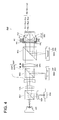
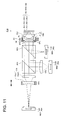
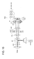
- Fig. 1 is a view generally showing a structure of the first optical pick-up device PU1 by which the recording/reproducing of the information can be adequately conducted on any one of the high density optical disk HD (the first optical disk), DVD (the second optical disk) and CD (the third optical disk).
- HD the first optical disk
- DVD the second optical disk
- CD the third optical disk
- a combination of the wavelength, thickness of the protective layer, and numerical aperture is not limited to this.
- the optical pick-up device PU1 is structured by: the blue violet semiconductor laser LD1 (the first light source) projecting the laser light flux (the first light flux) of 408 nm which is light-emitted when the recording/reproducing of the information is conducted on the high density optical disk HD; red semiconductor laser LD2 (the second light source) projecting the laser light flux (the second light flux) of 658 nm which is light-emitted when the recording/reproducing of the information is conducted on DVD; light detector PD12 common to the first light flux and the second light flux; CD use module MD3 in which the infrared semiconductor laser LD3 (the third light source) projecting the laser light flux (the third light flux) of 785 nm which is light-emitted when the recording/reproducing of the information is conducted on CD, and the light detector PD3 are integrated; beam expander optical system EXP as the aberration correction optical system; one-axis actuator UAC; objective optical system OBJ having a function by which each of laser light fluxes is light-
- the beam expander optical system is structured by a glass lens (the first lens EXP1) whose paraxial refractive power is negative, and a plastic lens (the second lens EXP2) whose paraxial refractive power is positive, and arranged in the common optical path of the first light flux and the second light flux.
- the blue violet semiconductor laser LD1 is light-emitted.
- the divergent light flux projected from the blue violet semiconductor laser LD1 is converted into the parallel light flux by transmitting the first collimator optical system COL1, it transmits the first and the second beam combiners BC1 and BC2, first lens EXP1, second lens EXP2, third beam combiner BC3, in order, and becomes a spot formed on the information recording surface RL1 through the protective layer PL1 of the high density optical disk HD by the objective optical system OBJ.
- the objective optical system OBJ conducts focusing or tracking by the 2-axis actuator AC arranged in its periphery.
- the reflected light flux modulated by the information pit on the information recording surface RL1 transmits again the objective optical system OBJ, the third beam combiner BC3, the second lens EXP2 and the first lens EXP1 of the beam expander optical system EXP, and is branched by the second beam combiner BC2, passes the sensor lens SEN, and is converged on the light receiving surface of the light detector PD12. Then, by using the output signal of the light detector PD12, the information recorded in the high density optical disk HD can be read.
- the red semiconductor laser LD2 is light-emitted.
- the divergent light flux projected from the red semiconductor laser LD2 is reflected by the first beam combiner BC1, transmits the second beam combiner BC2, first lens EXP1, second lens EXP2, third beam combiner BC3, in order, and becomes a spot formed on the information recording surface RL2 by the objective optical system OBJ through the protective layer of DVD.
- the objective optical system OBJ conducts the focusing or tracking by 2-axis actuator AC arranged in the periphery of it.
- the reflected light flux modulated by the information pit on the information recording surface RL2 transmits again the objective optical system OBJ, the third beam combiner BC3, second lens EXP2, first lens EXP1, and is branched by the second beam combiner BC2, passes the sensor lens SEN, and is converged on the light receiving surface of the light detector PD12. Then, by using the output signal of the light detector PD12, the information recorded in DVD can be read.
- the CD use module MD3 is actuated and the infrared semiconductor laser LD3 is light-emitted.
- the divergent light flux projected from the infrared semiconductor laser LD3 becomes a spot formed on the information recording surface RL3 by the objective optical system OBJ through the protective layer of CD, after it is reflected by the third beam combiner BC3.
- the objective optical system OBJ conducts the focusing or tracking by the 2-axis actuator AC arranged in the periphery of it.
- the reflected light flux modulated by the information pit on the information recording surface RL3 is, after it transmits again the objective optical system OBJ, reflected by the third beam combiner BC3, and is converged on the light receiving surface of the light detector PD3 of the CD use module MD3. Then, by using the output signal of the light detector PD3, the information recorded in CD can be read.
- a package light source unit in which the blue violet semiconductor laser LD1 and the red semiconductor laser LD2 are integrated, and housed in a casing, can also be used.
- the first beam combiner BC1 can be deleted, and for example, the second collimator optical system COL2 can be deleted.
- the objective optical system OBJ is the same structure also in the second - the fourth, and the sixth - the ninth embodiments, which will be described later.
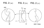
- the objective optical system OBJ is structured, as shown in Fig. 2 and Fig. 3, by the aberration correction element L1 and the light collecting element L2 both surfaces of which are aspheric surfaces, having a function for collecting the laser light flux which transmits this aberration correction element L1, on the information recording surface of the optical disk.
- Both of the aberration correction element L1 and the light collecting element L2 are plastic lenses, and in the periphery of respective optical function sections, flange sections FL1, FL2 which are integrally molded with the optical function section, are formed, and when mutual one-portions of such flange sections FL1, FL2 are engaged, they are integrated.
- the optical function surface S1 on the light source side of the aberration correction element L1 is, as shown in Fig. 3(a), is divided into the first area AREA1 corresponding to an area to the numerical aperture 0.67 of DVD, and the second area AREA2 corresponding to an area from the numerical aperture 0.67 of DVD to the numerical aperture 0.85 of the high density optical disk HD, and as shown in Fig. 2(a), the step type diffractive structure HOE which is the structure in which a plurality of ring-shaped zones inside of which the step structure is formed, are arranged around the optical axis, is formed in the first area AREA1.
- the laser light flux of wavelength ⁇ 1 When, on this step type diffractive structure HOE, the laser light flux of wavelength ⁇ 1 is incident, the optical path difference of 2 ⁇ ⁇ 1 ( ⁇ m) is generated between adjoining steps, and because, to the laser light flux of wavelength ⁇ 1, practically the phase difference is not given, the laser light flux transmits without being diffracted, as it is.
- the light flux which transmits as it is, without the phase difference being given practically, by the step type diffractive structure is referred to as 0-order diffraction light.
- the objective optical system OBJ when the magnifications to wavelength ⁇ 1 and wavelength ⁇ 3 are made different, the spherical aberration due to the difference of thickness of protective layers of the high density optical disk HD and CD, is corrected.
- the optical function surface S2 on the optical disk side of the aberration correction element L1 is, as shown in Fig. 3(c), divided into the third area AREA3 including the optical axis corresponding to an area within the numerical aperture 0.67 of DVD, and the fourth area AREA4 corresponding to an area from the numerical aperture 0.67 of DVD to the numerical aperture 0.85 of the high density optical disk HD, and a blaze type diffractive structure DOE1 is formed in the third area AREA3, and a blaze type diffractive structure DOE2 is formed in the fourth area AREA4.
- the blaze type diffractive structures DOE1 and DOE2 are structures for correcting the chromatic aberration of the objective optical system OBJ in the blue violet area.
- the optical function surface S2 on the optical disk side of the aberration correction element L1 is an aspheric surface having the convex shape on the optical disk side in a paraxial portion.
- the structure of the compatible type optical device can be made simple.
- the refractive power of the plastic lens in the aberration correction optical system is uniquely determined depending on the temperature characteristic of the objective optical system, when the aberration correction optical system is structured only by the plastic lenses, the degree of freedom for determining the paraxial amount such as the magnification of the aberration correction optical system is insufficient, however, in the optical pick-up device of the present embodiment, because the refractive power of the glass lens which is not affected by influence of the temperature change, arranged in the aberration correction optical system, can be freely selected, it can cope with various specifications of the aberration correction optical system.
- the temperature characteristic can be corrected also at the time of the recording/reproducing on DVD using the second light flux. Further, when the first lens EXP1 of the beam expander optical system EXP is moved by the one axis actuator UAC, not only at the time of the recording/reproducing on the high density optical disk, but also at the time of the recording/reproducing on DVD, the spherical aberration can be corrected.
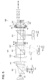
- the collimator optical system COL a glass lens whose paraxial refractive power is negative, (the first lens EXP1) in the beam expander optical system EXP; second beam combiner BC2; a plastic lens (the second lens EXP2) whose paraxial refractive power is positive, in the beam expander optical system EXP; and objective optical system OBJ, are arranged in order, from the blue violet semiconductor laser LD1 side.
- the blue violet semiconductor laser LD1 is light-emitted.
- the divergent light flux projected from the blue violet semiconductor laser LD1 passes the first beam combiner BC1, and transmits the collimator optical system COL, after it is converted into a parallel light flux, it passes the first lens EXP1, second beam combiner BC2, second lens EXP2, third beam combiner BC3, in order, and becomes a spot formed on the information recording surface RL1 through the protective layer PL1 of the high density optical disk HD by the objective optical system OBJ.
- the red semiconductor laser is light-emitted.
- the divergent light flux projected from the red semiconductor laser LD2 is reflected by the second beam combiner BC2, and after converted into a parallel light flux in the second lens EXP2, passes the third beam combiner BC3 in order, and becomes a spot formed on the information recording surface RL2 through the protective layer PL2 of DVD by the objective optical system OBJ.
- the objective optical system OBJ conducts the focusing or tracking by the 2-axis actuator AC arranged in the periphery of it.
- the reflected light flux modulated by an information pit on the information recording surface RL2 passes again the objective optical system OBJ, third beam combiner BC3, second lens EXP2, and is branched by the second beam combiner BC2, and converged on the light receiving surface of the light detector PD2.
- the output signal of the light detector PD2 the information recorded in DVD can be read.
- the CD use module MD3 is actuated and the red semiconductor laser LD3 is light-emitted.
- the objective optical system OBJ conducts the focusing or tracking by the 2-axis actuator AC arranged in the periphery of it.
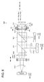
- the optical pick-up device PU3 is structured by: the blue violet semiconductor laser LD1 projecting the first light flux; light detector PD1, DVD use module MD2 into which the red semiconductor laser LD2 projecting the second light flux, and light detector PD2 are integrated; CD use module MD3 into which the infrared semiconductor laser LD3 and light detector PD3 are integrated; beam expander optical system EXP as the aberration correction optical system; one axis actuator UAC; objective optical system OBJ; 2-axis actuator AC; the first beam combiner BC1; second beam combiner BC2; third beam combiner BC3; collimator optical system COL; and coupling optical system CUL3.
- the collimator optical system COL plastic lens (the second lens EXP2) whose paraxial refractive power is positive, in the beam expander optical system EXP, second beam combiner BC2, glass lens (the first lens EXP1) whose paraxial refractive power is negative, in the beam expander optical system EXP, and the objective optical system OBJ, are arranged in order from the blue violet semiconductor laser LD1 side.
- the blue violet semiconductor laser LD1 is light-emitted.
- the divergent light flux projected from the blue violet semiconductor laser LD1 passes the first beam combiner BC1, and after converted into the parallel light flux by passing the collimator optical system COL, passes the second lens EXP2, second beam combiner BC2, first lens EXP1, and third beam combiner BC3, in order, and becomes a spot formed on the information recording surface RL1 through the protective layer PL1 of the high density optical disk HD by the objective optical system OBJ.
- the objective optical system OBJ conducts the focusing or tracking, by the 2-axis actuator AC arranged in its periphery.
- the reflected light flux modulated by an information pit on the information recording surface RL1 transmits again the objective optical system OBJ, the third beam combiner BC3, first lens EXP1, second beam combiner BC2, second lens EXP2, and collimator optical system COL, and is branched by the first beam combiner BC1, passes the sensor lens SEN, and is converged on the light receiving surface of the light detector PD1.
- the output signal of the light detector PD1 the information recorded in the high density optical disk HD can be read.
- the CD use module is actuated and the red semiconductor laser LD3 is light-emitted.
- the objective optical system OBJ conducts the focusing or tracking by the 2-axis actuator AC arranged in the periphery of it.
- the plastic lens (the second lens EXP2) in the beam expander optical system EXP is in the exclusive use optical path of the first light flux, the existence of the beam expander optical system EXP does not affect the temperature characteristic at the time of the recording/reproducing on DVD using the second light flux. Accordingly, by considering only that the temperature characteristic at the time of the recording/reproducing on the high density optical disk using the first light flux is corrected, the refractive power of the plastic lens (the second lens EXP2) can be determined.
- the optical pick-up device PU4 is structured by: the high density optical disk use module MD1 into which the blue violet semiconductor laser LD1 projecting the first light flux and light detector PD1 are integrated; DVD use module MD2 into which the red semiconductor laser LD2 projecting the second light flux, and light detector PD2 are integrated; CD use module MD3 into which the infrared semiconductor laser LD3 projecting the third light flux and light detector PD3 are integrated; beam expander optical system EXP as the aberration correction optical system; one axis actuator UAC; objective optical system OBJ; 2-axis actuator AC; the first beam combiner BC1; second beam combiner BC2; first collimator optical system COL1; and second collimator optical system COL2.
- the blue violet semiconductor laser LD1 is light-emitted.
- the divergent light flux projected from the blue violet semiconductor laser LD1 after converted into the parallel light flux by passing the first collimator optical system, passes the first lens EXP1 (glass lens whose paraxial refractive power is negative), second lens EXP2 (plastic lens whose paraxial refractive power is positive), the first beam combiner BC1, second beam combiner BC2, in order, and becomes a spot formed on the information recording surface RL1 through the protective layer PL1 of the high density optical disk HD by the objective optical system OBJ.
- the objective optical system OBJ conducts the focusing or tracking, by the 2-axis actuator AC arranged in its periphery.
- the reflected light flux modulated by an information pit on the information recording surface RL1 transmits again the objective optical system OBJ, the second beam combiner BC2, first beam combiner BC1, second lens EXP2, first lens EXP1, and first collimator optical system COL, and is converged on the light receiving surface of the light detector PD1.
- the output signal of the light detector PD1 the information recorded in the high density optical disk HD can be read.
- the red semiconductor laser LD2 is light-emitted.
- the objective optical system OBJ conducts the focusing or tracking by the 2-axis actuator AC arranged in the periphery of it.
- the reflected light flux modulated by an information pit on the information recording surface RL2 passes again the objective optical system OBJ, second beam combiner BC2, and is branched by the first beam combiner BC1, when it passes the collimator optical system COL2, after it is converted into converging light flux, it is converged on the light receiving surface of the light detector PD2.
- the output signal of the light detector PD2 the information recorded in DVD can be read.
- the plastic lens (the second lens EXP2) in the beam expander optical system EXP is in the exclusive use optical path of the first light flux, the existence of the beam expander optical system EXP does not affect the temperature characteristic at the time of the recording/reproducing on DVD using the second light flux. Accordingly, by considering only a case where the temperature characteristic at the time of the recording/reproducing on the high density optical disk using the first light flux is corrected, the refractive power of the plastic lens (the second lens EXP2) can be determined.
- the combination of the wavelength, thickness of the protective layer, and numerical aperture is not limited to this.
- the beam expander optical system EXP is arranged in the common optical path of the first light flux, second light flux and third light flux.
- the blue violet semiconductor laser LD1 is light-emitted.
- the divergent light flux projected from the blue violet semiconductor laser LD1 after it is converted into a parallel light flux when it transmits the first collimator optical system COL1, passes the first beam combiner BC1, second beam combiner BC2, third beam combiner BC3, first lens EXP1 (glass lens whose paraxial refractive power is negative), second lens EXP2 (plastic lens whose paraxial refractive power is positive), in order, and becomes a spot formed on the information recording surface RL1 through the protective layer PL1 of the high density optical disk HD by the objective optical system OBJ'.
- the red semiconductor laser LD2 is light-emitted.
- the objective optical system OBJ' conducts the focusing or tracking by the 2-axis actuator AC arranged in the periphery of it.
- the reflected light flux modulated by an information pit on the information recording surface RL2 passes again the objective optical system OBJ', second lens EXP2, first lens EXP1, and is branched by the third beam combiner BC3, passes the sensor lens SEN, and it is converged on the light receiving surface of the light detector PD123.
- the output signal of the light detector PD123 the information recorded in DVD can be read.
- the infrared semiconductor LD3 is light-emitted.
- a packaged light source unit into which the blue violet semiconductor laser LD1 and red semiconductor laser LD2 are integrated and housed in a casing can also be used.
- the first beam combiner BC1 can be deleted, and the collimator optical systems can be made two, and for example, the second collimator optical system COL2 can be deleted.
- a packaged light source unit into which the blue violet semiconductor laser LD1, red semiconductor laser LD2, and infrared semiconductor laser LD3 are integrated and housed in a casing can also be used.
- the first and second beam combiners BC1, BC2 can be deleted, and the collimator optical system can be made one, and for example, the second and third collimator optical systems COL2, COL3 can be deleted.
- the objective optical system OBJ' when the magnifications to the wavelength ⁇ 1 and wavelength ⁇ 3 are made different, the spherical aberration due to the difference of thickness of the protective layer between the high density optical disk and CD, is corrected.
- the glass lens in the fifth embodiment, the first lens EXP1, in the tenth embodiment, the first lens CUL1
- the magnification of the objective optical system OBJ' is changed.
- the plastic lens (the second lens EXP2) in the beam expander optical system EXP is in the common optical path of the first light flux, second light flux and third light flux, when the objective optical system OBJ' has the temperature characteristic in which the spherical aberration changes in the over correction direction following the temperature rise at the time of the recording/reproducing of DVD or CD, by the action of the second lens EXP2, the temperature characteristic at the time of the recording/reproducing on DVD or CD can also be corrected.
- the second lens EXP2 can be moved by the one axis actuator UAC, the spherical aberration can be corrected not only at the time of the recording/reproducing on the high density optical disk, but also at the time of the recording/reproducing on DVD and CD.
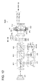
- the optical pick-up device PU6 is structured by: a light source unit LU1 into which the blue violet semiconductor laser LD1 projecting the first light flux and the red semiconductor laser LD2 projecting the second light flux are integrated; light detector PD12 common to the first light flux and the second light flux; CD use module MD3 into which the infrared semiconductor laser LD3 projecting the third light flux and light detector PD3 are integrated; coupling optical system CUL as the aberration correction optical system; one axis actuator UAC; objective optical system OBJ; two-axis actuator AC; first beam combiner BC1; and second beam combiner BC2.
- the blue violet semiconductor laser LD1 is light-emitted.
- the divergent light flux projected from the blue violet semiconductor laser LD1 passes the first beam combiner BC1, first lens CUL1 (glass lens whose paraxial refractive power is negative), second lens CUL2 (plastic lens whose paraxial refractive power is positive), second beam combiner BC2,in order, and becomes a spot formed on the information recording surface RL1 through the protective layer PL1 of the high density optical disk HD by the objective optical system OBJ.
- the coupling optical system CUL has a glass lens and a plastic lens whose refractive power is positive, the function of the aberration correction optical system for correcting the temperature characteristic of the objective optical system OBJ, OBJ', can be given to the coupling optical system CUL, and it is advantageous for the reduction of the number of parts of the optical pick-up device, cost reduction, and size reduction.
- the beam shaping element for shaping the sectional shape of the laser light flux projected from the blue violet semiconductor laser LD1, from the ellipse shape to circular is used, it is preferable that the beam shaping element at least one optical surface of which is a cylindrical surface, is arranged in the optical path between the blue violet semiconductor laser LD1 and the coupling optical system.
- the coupling optical system CUL is arranged in the common optical path of the first light flux and the second light flux, when the objective optical system OBJ has the temperature characteristic in which the spherical aberration changes in the over correction direction following the temperature rise at the time of the recording/reproducing of DVD, by the action of the second lens CUL2, the temperature characteristic at the time of the recording/reproducing on DVD can also be corrected. Further, when the first lens CUL1 is moved by the one axis actuator, not only at the time of the recording/reproducing on the high density optical disk, but also at the time of the recording/reproducing on DVD, the spherical aberration can be corrected.
- the optical pick-up device PU7 is structured by: the blue violet semiconductor laser LD1 projecting the first light flux; red semiconductor laser LD2 projecting the second light flux; light detector PD12 common to the first light flux and second light flux; CD use module MD3 into which the infrared semiconductor laser LD3 projecting the third light flux and the light detector PD3 are integrated; coupling optical system CUL as the aberration correction optical system; one axis actuator UAC; objective optical system OBJ; two-axis actuator AC; first beam combiner BC1; second beam combiner BC2; and third beam combiner BC3.
- a glass lens (the first lens CUL1) whose paraxial refractive power is negative, in the coupling optical system CUL, second beam combiner BC2, plastic lens (the second lens CUL2) whose paraxial refractive power is positive, in the coupling optical system CUL, objective optical system OBJ, are arranged in order from the blue violet semiconductor laser LD1 side.
- the blue violet semiconductor laser LD1 is light-emitted.
- the divergent light flux projected from the blue violet semiconductor laser LD1 passes the first lens CUL1, first beam combiner BC1, second beam combiner BC2, after it is converted into the parallel light flux in the second lens CUL2, passes the third beam combiner BC3, and becomes a spot formed on the information recording surface RL1 through the protective layer PL1 of the high density optical disk HD by the objective optical system OBJ.
- the red semiconductor laser LD2 When the recording/reproducing of the information is conducted on DVD, as the path of ray is shown by a dotted line in Fig. 9, initially, the red semiconductor laser LD2 is light-emitted.
- the divergent light flux projected from the red semiconductor laser LD2 is reflected by the first beam combiner BC1, passes the second beam combiner BC2, after it is converted into a parallel light flux in the second lens CUL2, passes the third beam combiner BC3, and becomes a spot formed on the information recording surface RL2 through the protective layer PL2 of DVD by the objective optical system OBJ.
- the CD use module MD3 is actuated and the infrared semiconductor LD3 is light-emitted.
- the divergent light flux projected from the infrared semiconductor laser LD3 is reflected by the third beam combiner BC3, and becomes a spot formed on the information recording surface RL3 through the protective layer PL3 of CD by the objective optical system OBJ.
- the objective optical system OBJ conducts the focusing or tracking by the 2-axis actuator AC arranged in the periphery of it.
- the reflected light flux modulated by an information pit on the information recording surface RL3 passes again the objective optical system OBJ, and is branched by the third beam combiner BC3, and converged on the light receiving surface of the light detector PD3. Then, by using the output signal of the light detector PD3, the information recorded in CD can be read.
- the plastic lens (the second lens CUL2) in the coupling optical system CUL is arranged in the common optical path of the first light flux and the second light flux, when the objective optical system OBJ has the temperature characteristic in which the spherical aberration changes in the over correction direction following the temperature rise at the time of the recording/reproducing of DVD, by the action of the second lens CUL2, the temperature characteristic at the time of the recording/reproducing on DVD can also be corrected.
- the second lens CUL2 is served both as the collimator optical system of the second light flux, the number of parts can be reduced. Further, when the second lens is moved by the one axis actuator UAC, not only at the time of the recording/reproducing on the high density optical disk, but also at the time of the recording/reproducing on DVD, the spherical aberration can be corrected.
- the coupling optical system CUL is structured by the second lens CUL2 in which a glass lens whose paraxial refractive power is negative, and a plastic lens whose paraxial refractive power is positive, are cemented, and a glass lens whose paraxial refractive power is positive, and in the optical pick-up device PU8 in the present embodiment, the second lens CUL2 in the coupling optical system CUL, second beam combiner BC2, a glass lens (the first lens CUL1) in the coupling optical system CUL, and objective optical system OBJ, are arranged in order from the blue violet semiconductor laser LD1 side.
- the red semiconductor laser LD2 When the recording/reproducing of the information is conducted on DVD, as the path of ray is shown by a dotted line in Fig. 10, initially, the red semiconductor laser LD2 is light-emitted.
- the divergent light flux projected from the red semiconductor laser LD2 is reflected by the second beam combiner BC2, after it is converted into a parallel light flux in the first lens CUL1, it passes the third beam combiner BC3, and becomes a spot formed on the information recording surface RL2 through the protective layer PL2 of DVD by the objective optical system OBJ.
- the objective optical system OBJ conducts the focusing or tracking by the 2-axis actuator AC arranged in the periphery of it.
- the reflected light flux modulated by an information pit on the information recording surface RL2 passes again the objective optical system OBJ, third beam combiner BC3, first lens CUL1, and is branched by the second beam combiner BC2, and is converged on the light receiving surface of the light detector PD2.
- the output signal of the light detector PD2 the information recorded in DVD can be read.
- the CD use module MD3 is actuated and the infrared semiconductor LD3 is light-emitted.
- the divergent light flux projected from the infrared semiconductor laser LD3 is reflected by the third beam combiner BC3, and becomes a spot formed on the information recording surface RL3 through the protective layer PL3 of CD by the objective optical system OBJ.
- the objective optical system OBJ conducts the focusing or tracking by the 2-axis actuator AC arranged in the periphery of it.
- the reflected light flux modulated by an information pit on the information recording surface RL2 passes again the objective optical system OBJ, and is branched by the third beam combiner BC3, and converged on the light receiving surface of the light detector PD3.
- the output signal of the light detector PD3 the information recorded in CD can be read.
- the second lens CUL2 including the plastic lens in the coupling optical system CUL is arranged in the exclusive use optical path of the first light flux, the existence of the coupling optical system CUL does not affect the temperature characteristic at the time of the recording/reproducing on DVD using the second light flux. Accordingly, by considering only case where the temperature characteristic at the time of the recording/reproducing on the high density optical disk using the first light flux is corrected, the refractive power of the plastic lens in the second lens CUL2 can be determined. Further, because the first lens CUL1 serves both as the collimator optical system of the second light flux, the number of parts can be reduced.
- the second lens CUL2 is moved by the one axis actuator UAC, not only at the time of the recording/reproducing on the high density optical disk, but also at the time of the recording/reproducing on DVD, the spherical aberration can be corrected.
- the optical pick-up device PU9 is structured by: the high density optical disk use module MD1 into which the blue violet semiconductor laser LD1 projecting the first light flux and the light detector PD1 are integrated; DVD use module MD2 into which the red semiconductor laser LD2 projecting the second light flux and the light detector PD2 are integrated; CD use module MD3 into which the infrared semiconductor laser LD3 projecting the third light flux and the light detector PD3 are integrated; coupling optical system CUL as the aberration correction optical system; one axis actuator UAC; objective optical system OBJ; two-axis actuator AC; first beam combiner BC1; second beam combiner BC2; and collimator optical system COL.
- the high density optical disk use module MD1 into which the blue violet semiconductor laser LD1 projecting the first light flux and the light detector PD1 are integrated
- DVD use module MD2 into which the red semiconductor laser LD2 projecting the second light flux and the light detector PD2 are integrated
- CD use module MD3 into which the infrared semiconductor laser
- the coupling optical system CUL is arranged in the exclusive use optical path of the first light flux.
- the objective optical system OBJ conducts the focusing or tracking by the 2-axis actuator AC arranged in the periphery of it.
- the reflected light flux modulated by an information pit on the information recording surface RL1 passes again the objective optical system OBJ, second beam combiner BC2, first beam combiner BC1, second lens CUL2, first lens CUL1, in order, and converged on the light receiving surface of the light detector PD1.
- the output signal of the light detector PD1 the information recorded in the high density optical disk HD can be read.
- the red semiconductor laser LD2 When the recording/reproducing of the information is conducted on DVD, as the path of ray is shown by a dotted line in Fig. 11, initially, the red semiconductor laser LD2 is light-emitted.
- the divergent light flux projected from the red semiconductor laser LD2 is, after it is converted into a parallel light flux by passing the collimator optical system COL, reflected by the first beam combiner BC1, passes the second beam combiner BC2, and becomes a spot formed on the information recording surface RL2 through the protective layer PL2 of DVD by the objective optical system OBJ.
- the objective optical system OBJ conducts the focusing or tracking by the 2-axis actuator AC arranged in the periphery of it.
- the reflected light flux modulated by an information pit on the information recording surface RL2 passes again the objective optical system OBJ, second beam combiner BC2, and is branched by the first beam combiner BC1, passes the collimator optical system COL, and is converged on the light receiving surface of the light detector PD2.
- the output signal of the light detector PD2 the information recorded in DVD can be read.
- the CD use module MD3 is actuated and the infrared semiconductor LD3 is light-emitted.
- the divergent light flux projected from the infrared semiconductor laser LD3 is reflected by the second beam combiner BC2, and becomes a spot formed on the information recording surface RL3 through the protective layer PL3 of CD by the objective optical system OBJ.
- the objective optical system OBJ conducts the focusing or tracking by the 2-axis actuator AC arranged in the periphery of it.
- the reflected light flux modulated by an information pit on the information recording surface RL3 passes again the objective optical system OBJ, and is branched by the third beam combiner BC3, and converged on the light receiving surface of the light detector PD3. Then, by using the output signal of the light detector PD3, the information recorded in CD can be read.
- the plastic lens (the second lens CUL2) in the coupling optical system CUL is arranged in the exclusive use optical path of the first light flux, the existence of the coupling optical system CUL does not affect the temperature characteristic at the time of the recording/reproducing on DVD using the second light flux. Accordingly, by considering only case where the temperature characteristic at the time of the recording/reproducing on the high density optical disk using the first light flux is corrected, the refractive power of the plastic lens (the second lens CUL2) can be determined.
- the optical pick-up device PU10 is structured by: the blue violet semiconductor laser LD1 projecting the first light flux; red semiconductor laser LD2 projecting the second light flux; infrared semiconductor laser LD3 projecting the third light flux; light detector PD123 common to the first - third light fluxes; coupling optical system CUL as the aberration correction optical system; one axis actuator UAC; objective optical system OBJ'; two-axis actuator AC; first beam combiner BC1; second beam combiner BC2; and third beam combiner BC3.
- the blue violet semiconductor laser LD1 is light-emitted.
- the divergent light flux projected from the blue violet semiconductor laser LD1 passes the first beam combiner BC1, second beam combiner BC2, third beam combiner BC3, first lens CUL1 (glass lens whose paraxial refractive power is negative), second lens CUL2 (plastic lens whose paraxial refractive power is positive), in order, and becomes a spot formed on the information recording surface RL1 through the protective layer PL1 of the high density optical disk HD by the objective optical system OBJ'.
- the red semiconductor laser LD2 is light-emitted.
- the divergent light flux projected from the red semiconductor laser LD2 is reflected by the first beam combiner BC1, passes the second beam combiner BC2, third beam combiner BC3, first lens CUL1, second lens CUL2, in order, and becomes a spot formed on the information recording surface RL2 through the protective layer PL2 of DVD by the objective optical system OBJ'.
- the objective optical system OBJ' conducts the focusing or tracking by the 2-axis actuator AC arranged in the periphery of it.
- the reflected light flux modulated by an information pit on the information recording surface RL2 passes again the objective optical system OBJ', second lens CUL2, first lens CUL1, and is branched by the third beam combiner BC3, passes the sensor lens SEN, and is converged on the light receiving surface of the light detector PD123.
- the output signal of the light detector PD123 the information recorded in DVD can be read.
- the infrared semiconductor LD3 is light-emitted.
- the divergent light flux projected from the infrared semiconductor laser LD3 is reflected by the second beam combiner BC2, passes the first lens CUL1, second lens CUL2, in order, and becomes a spot formed on the information recording surface RL3 through the protective layer PL3 of CD by the objective optical system OBJ'.
- the objective optical system OBJ' conducts the focusing or tracking by the 2-axis actuator AC arranged in the periphery of it.
- the reflected light flux modulated by an information pit on the information recording surface RL3 passes again the objective optical system OBJ', second lens CUL2, first lens CUL1, and is branched by the third beam combiner BC3, passes the sensor lens SEN, and converged on the light receiving surface of the light detector PD123.
- the output signal of the light detector PD123 the information recorded in CD can be read.
- the plastic lens (the second lens CUL2) in the coupling optical system CUL is arranged in the common optical path of the first light flux, second light flux and third light flux, when the objective optical system OBJ' has the temperature characteristic in which the spherical aberration changes in the over correction direction following the temperature rise at the time of the recording/reproducing of DVD or CD, by the action of the second lens CUL2, the temperature characteristic at the time of the recording/reproducing on DVD or CD, can also be corrected.
- the glass lens (the first lens CUL1) in the coupling optical system is moved by the one axis actuator UAC, not only at the time of the recording/reproducing on the high density optical disk, but also at the time of the recording/reproducing on DVD and CD, the spherical aberration can be corrected.
- the combination of the wavelength, thickness of the protective layer, and numerical aperture is not limited to this.
- the optical pick-up device PU11 is structured by: a laser light source unit LD123 into which the blue violet semiconductor laser LD1 projecting the first light flux, red semiconductor laser LD2 projecting the second light flux, and infrared semiconductor laser LD3 projecting the third light flux, are integrated; light detector PD123 common to the first - third light flux; beam expander optical system EXP as the aberration correction optical system; one axis actuator UAC; objective optical system OBJ"; two-axis actuator AC; beam combiner BC; and collimator optical system COL.
- the beam expander optical system EXP is arranged in the common optical path of the first light flux, second light flux and third light flux.
- the blue violet semiconductor laser LD1 is light-emitted.
- the divergent light flux projected from the blue violet semiconductor laser LD1, as its path of ray is shown by a solid line in Fig.
- the red semiconductor laser LD2 is light-emitted.
- the divergent light flux projected from the red semiconductor laser LD2, as its path of ray is shown by a dotted line in Fig. 15, is reflected by the beam combiner BC, and when transmits the collimator optical system COL, after it is converted into almost parallel light flux, by transmitting the first lens EXP1, second lens EXP2, it is converted into the parallel light flux. After that, it becomes a spot formed on the information recording surface RL2 through the protective layer PL2 of DVD by the objective optical system OBJ".
- the objective optical system OBJ conducts the focusing or tracking by the 2-axis actuator AC arranged in the periphery of it.
- the reflected light flux modulated by an information pit on the information recording surface RL1 passes again the objective optical system OBJ", second lens EXP2, first lens EXP1, and after it is converted into the converging light flux, by transmitting the collimator optical system COL, passes the beam combiner BC, sensor lens SEN, and is converged on the light receiving surface of the light detector PD123. Then, by using the output signal of the light detector PD123, the information recorded in DVD can be read.
- the objective optical system OBJ conducts the focusing or tracking by the 2-axis actuator AC arranged in the periphery of it.
- the reflected light flux modulated by an information pit on the information recording surface RL3 passes again the objective optical system OBJ", second lens EXP2, first lens EXP1, and when it transmits the collimator optical system COL, after it is converted into the converging light flux, passes the beam combiner BC, sensor lens SEN, and is converged on the light receiving surface of the light detector PD123. Then, by using the output signal of the light detector PD123, the information recorded in CD can be read.
- the objective optical system OBJ is, as its general structural view is shown in Fig. 16, structured by the aberration correction element L1 and the light converging element L2 which has the function by which the laser light flux transmitted this aberration correction element L1 is light-converged on the information recording surface of the optical disk, and whose both surfaces are aspheric surfaces.
- Both of the aberration correction element L1 and the light converging element L2 are plastic lenses, and integrated through a mirror frame LB.
- the optical function surface S1 on the light source side of the aberration correction element L1 is divided into the first area AREA1 corresponding to an area up to the numerical aperture 0.65 of DVD, and the second area AREA2 corresponding to an area from the numerical aperture 0.65 of DVD to the numerical aperture 0.85 of the high density optical disk HD, (not shown), and a step type diffractive structure HOE in which a plurality of ring-shaped zones inside of which the step structure is formed, are arranged around the optical axis, is formed in the first area AREA1.
- the step type diffractive structure HOE is a structure for correcting the spherical aberration due to the difference of thickness of protective layers between the high density optical disk HD and DVD, and because its function or structure is the same as the step type diffractive structure HOE of above-described objective optical system OBJ, herein, the detailed description is omitted.
- the optical function surface S2 on the optical disk side of the aberration correction element L1 is divided into the third area AREA3 including the optical axis corresponding to an area within the numerical aperture 0.45 of CD, and the fourth area AREA4 corresponding to an area from the numerical aperture 0.45 of CD to the numerical aperture 0.85 of the high density optical disk HD, (not shown), and the step type diffractive structure HOE' which is a structure in which a plurality of ring-shaped zones inside of which the step structure is formed, are arranged around the optical axis, is formed in the third area AREA3.
- the step type diffractive structure HOE is formed in only an area within the numerical aperture NA2 of DVD, it is structured in such a manner that the light flux passes an area outside of NA2 becomes a flare component on the information recording surface RL2 of DVD, and the aperture limit to DVD is automatically conducted.
- the step type diffractive structure HOE' is formed in only an area within the numerical aperture NA3 of CD, it is structured in such a manner that the light flux passes an area outside of NA3 becomes a flare component on the information recording surface RL3 of CD, and the aperture limit to CD is automatically conducted.
- the spherical aberration of the objective optical system OBJ" has the temperature dependency which, at the time of the recording/reproducing on the high density optical disk HD, changes in the over correction direction when the temperature rises by 30 °C, however, to the change amount of the spherical aberration following the temperature change, the refractive power of the second lens EXP2 is optimized, and in the same manner as in the first embodiment, the spherical aberration following the temperature change as the entire system of the optical system structured by the beam expander optical system EXP and the objective optical system OBJ" is corrected.
- the plastic lens (the second lens EXP2) in the beam expander optical system EXP is in the common optical path of the first light flux, second light flux and third light flux, when the objective optical system OBJ" has the temperature characteristic in which the spherical aberration changes in the over correction direction following the temperature rise at the time of the recording/reproducing of DVD or CD, by the action of the second lens EXP2, the temperature characteristic at the time of the recording/reproducing on DVD or CD, can also be corrected.
- the first lens EXP1 can be moved by the one axis actuator UAC, the spherical aberration can be corrected at the time of the recording/reproducing not only on the high density optical disk, but also on DVD and CD.
- the focal distance of the beam expander optical system EXP can be adjusted so that light fluxes of respective wavelengths are projected from the beam expander optical system EXP under the condition of the parallel light flux.
- the laser light source unit LD123 and the light detector PD123 are separately arranged, however, it is not limited to this, a laser light source module into which the laser light source unit LD123 and the light detector PD123 are integrated, may be used.
- the reliability of the recording/reproducing of the optical pick-up device PU11 can be increased, that it is structured in such a manner that the diffractive structure is formed on the optical surface of the collimator optical system COL or beam expander optical system EXP, and the chromatic aberration in the blue violet wavelength area of the objective optical system OBJ" is corrected.
- the optical pick-up system in which the chromatic aberration is corrected by a simple structure can be obtained.
- a doublet lens in which a positive lens which has the positive refractive power and Abbe's number in d-ray is vd1, and a negative lens which has the negative refractive power and Abbe's number in d-ray is vd2 (vd2 ⁇ vd1), are cemented may also be arranged as an element structuring at least one part of the collimator optical system COL or beam expander optical system EXP.
- the shape of the diffractive structure is deviated from the design value by the production error, because the diffraction efficiency is lowered, the transmission of the optical pick-up system is lowered.
- the optical pick-up system in which the transmission is high can be obtained.
- the sensor lens SEN provided in the above optical pick-up devices PU1 - 3, 5 - 8, 10, 11, is a lens by which the astigmatism is given to the light flux reflected from the optical disk, which is toward the light detector.
- the superposition type diffractive structure (step type diffractive structure) in each example, or the diffractive structure is expressed by an optical path difference added to the transmission wave front by these structures.
- Such an optical path difference is expressed by the optical path difference function ⁇ b (mm) defined by the following expression (9) when ⁇ is a wavelength of an incident light flux, ⁇ B is a designed wavelength, the height in the direction perpendicular to the optical axis is h (mm), B 2j is an optical path difference function coefficient, and n is a diffraction order number.
- the beam expander optical system EXP which is composed of two lenses of a glass lens whose paraxial refractive power is negative, and a plastic lens whose paraxial refractive power is positive, is arranged in the common optical path of the wavelength ⁇ 1 and the wavelength ⁇ 2, further, the beam combiner for leading an optical path of the light flux having the wavelength ⁇ 3 into a common optical path of the light flux having the wavelength ⁇ 1 and the light flux having the wavelength ⁇ 2, is arranged in the optical path between the beam expander optical system EXP and the objective optical system OBJ.
- the spherical aberration of the objective optical system OBJ in the present example has the temperature dependency in which, when the temperature rises by 30 °C, it changes in the over correction direction, and the change amount of the wave front aberration due to this, is 0.057 ⁇ RMS.
- the objective optical system OBJ having such a temperature characteristic is combined with the beam expander optical system EXP, the change amount of the wave front aberration when the temperature rises by 30 °C, can be suppressed to 0.010 ⁇ RMS.
- the refractive index change rate of the plastic lens of the beam expander optical system EXP and the first plastic lens (aberration correction element L1) of the objective optical system OBJ is made -1.1 ⁇ 10 -4 /°C
- the refractive index change rate of the second plastic lens (light converging element L2) of the objective optical system OBJ is made -0.9 ⁇ 10 -4 /°C.
- Example 2 is the optimum optical system as the optical pick-up system mounted on the second optical pick-up device PU2, and its specific numeric value data is shown in Table 3.
- the beam combiner for leading an optical path of the light flux having the wavelength ⁇ 3 into a common optical path of the light flux having the wavelength ⁇ 1 and the light flux having the wavelength ⁇ 2 is arranged.
- the objective optical system OBJ in the present example is the same as the objective optical system OBJ in the above-described example 1, and when the temperature rises by 30 °C, it has the temperature dependency in which the spherical aberration changes in the over correction direction, and due to this, the wave front aberration changes in 0.057 ⁇ RMS.
- this objective optical system OBJ is combined with the beam expander optical system EXP, the change amount of the wave front aberration when the temperature rises by 30 °C, can be suppressed to 0.011 ⁇ RMS.
- the refractive index change rate of the plastic lens of the beam expander optical system EXP and the first plastic lens L1 of the objective optical system OBJ is made -1.1 ⁇ 10 -4 /°C
- the refractive index change rate of the second plastic lens L2 of the objective optical system OBJ is made -0.9 ⁇ 10 -4 /°C.
- Example 3 is the optimum optical system as the optical pick-up system mounted on the third optical pick-up device PU3, and its specific numeric value data is shown in Table 4.
- the beam expander optical system EXP is composed of two lenses of a plastic lens whose paraxial refractive power is positive, and a glass lens whose paraxial refractive power is negative, and in the optical path between the glass lens and the plastic lens, the beam combiner for leading an optical path of the light flux having the wavelength ⁇ 2 into the optical path of the light flux having the wavelength ⁇ 1, is arranged.
- the divergent light flux of wavelength ⁇ 2 projected from the second light source LD2 is converted into the converging light flux by the coupling optical system, furthermore, by passing the glass lens in the beam expander optical system EXP, it becomes the parallel light.
- the beam combiner for leading an optical path of the light flux having the wavelength ⁇ 3 into a common optical path of the light flux having the wavelength ⁇ 1 and the light flux having the wavelength ⁇ 2, is arranged.
- the objective optical system OBJ in the present example is the same as the objective optical system OBJ in the above-described example 1, and when the temperature rises by 30 °C, it has the temperature dependency in which the spherical aberration changes in the over correction direction, and due to this, the wave front aberration changes in 0.057 ⁇ RMS.
- this objective optical system OBJ is combined with the beam expander optical system EXP, the change amount of the wave front aberration when the temperature rises by 30 °C, can be suppressed to 0.011 ⁇ RMS.
- the refractive index change rate of the plastic lens in the beam expander optical system EXP and the first plastic lens L1 of the objective optical system OBJ is made -1.1 ⁇ 10 -4 /°C
- the refractive index change rate of the second plastic lens L2 of the objective optical system OBJ is made -0.9 ⁇ 10 -4 /°C.
- Example 4 is the optimum optical system as the optical pick-up system mounted on the fourth optical pick-up device PU4, and its specific numeric value data is shown in Table 5.
- the collimator optical system COL is composed of a plastic lens whose paraxial refractive power is positive, and arranged in the exclusive use optical path of wavelength ⁇ 1.
- the beam expander optical system EXP is composed of the glass lens whose paraxial refractive power is negative, and the plastic lens whose paraxial refractive power is positive, and arranged in the exclusive use optical path of wavelength ⁇ 1.
- the beam combiner for leading an optical path of the light flux having the wavelength ⁇ 2 into the optical path of the light flux having the wavelength ⁇ 1 and the beam combiner for leading an optical path of the light flux having the wavelength ⁇ 3 into a common optical path of the light flux having the wavelength ⁇ 1 and the light flux having the wavelength ⁇ 2, are arranged.
- the objective optical system OBJ in the present example has the temperature dependency in which, when the temperature rises by 30 °C, the spherical aberration changes in the over correction direction, and due to this, the wave front aberration changes in 0.057 ⁇ RMS.
- this objective optical system OBJ is combined with the beam expander optical system EXP, the change amount of the wave front aberration when the temperature rises by 30 °C, can be suppressed to 0.011 ⁇ RMS.
- the refractive index change rate of the plastic lens of the collimator optical system COL, plastic lens of the beam expander optical system EXP and the first plastic lens L1 of the objective optical system OBJ is made -1.1 ⁇ 10 -4 /°C
- the refractive index change rate of the second plastic lens L2 of the objective optical system OBJ is made -0.9 ⁇ 10 -4 /°C.
- Example 5 is the optimum optical system as the optical pick-up system mounted on the sixth optical pick-up device PU6, and its specific numeric value data is shown in Table 6.
- the coupling optical system CUL which is composed of 2 lenses of a glass lens whose paraxial refractive power is negative, and a plastic lens whose paraxial refractive power is positive, is arranged in the common optical path of wavelength ⁇ 1 and wavelength ⁇ 2. Further, a beam combiner for leading an optical path of the light flux having the wavelength ⁇ 3 into a common optical path of the light flux having the wavelength ⁇ 1 and the light flux having the wavelength ⁇ 2, is arranged in the optical path between the coupling optical system CUL and the objective optical system OBJ.
- a beam combiner for leading the light flux of wavelength ⁇ 1 reflected by an information recording surface of an optical disk and the light flux of wavelength ⁇ 2 reflected by an information recording surface of an optical disk, into the light detector is arranged in the optical path between a package light source unit in which the light emitting point for projecting the light flux of wavelength ⁇ 1 and the light emitting point for projecting the light flux of wavelength ⁇ 2 are housed in a casing, and the coupling optical system CUL.
- the spherical aberration of the objective optical system OBJ in the present example has the temperature dependency in which, when the temperature rises by 30 °C, it changes in the over correction direction, and the change amount of the wave-front aberration due to this is 0.057 ⁇ RMS.
- the objective optical system OBJ having such a temperature characteristic is combined with the coupling optical system CUL, the change amount of the wave-front aberration when the temperature rises by 30 °C, can be suppressed to 0.010 ⁇ RMS.
- the refractive index change rate of the plastic lens of the coupling optical system CUL, and the first plastic lens L1 of the objective optical system OBJ is made -1.1 ⁇ 10 -4 /°C
- the refractive index change rate of the second plastic lens L2 of the objective optical system OBJ is made -0.9 ⁇ 10 -9 /°C.
- the coupling optical system CUL is composed of 2 lenses of a glass lens whose paraxial refractive power is negative, and a plastic lens whose paraxial refractive power is positive, and a beam combiner for leading an optical path of the light flux having the wavelength ⁇ 2 into the optical path of the light flux having the wavelength ⁇ 1, and a beam combiner for leading the light flux of wavelength ⁇ 1 reflected by an information recording surface of an optical disk and the light flux of wavelength ⁇ 2 reflected by an information recording surface of an optical disk, into the light detector, are arranged in the optical path of the plastic lens and glass lens.
- a beam combiner for leading an optical path of the light flux having the wavelength ⁇ 3 into a common optical path of the light flux having the wavelength ⁇ 1 and the light flux having the wavelength ⁇ 2, is arranged.
- the spherical aberration of the objective optical system OBJ in the present example has the temperature dependency in which, when the temperature rises by 30 °C, the spherical aberration changes in the over correction direction, and a change amount of the wave-front aberration due to this, is 0.057 ⁇ RMS.
- the objective optical system OBJ having such a temperature characteristic is combined with the coupling lens optical system CUL, the change amount of the wave front aberration when the temperature rises by 30 °C, can be suppressed to 0.011 ⁇ RMS.
- the refractive index change rate of the plastic lens of the coupling optical system CUL, and the first plastic lens L1 of the objective optical system OBJ is made -1.1 ⁇ 10 -4 /°C
- the refractive index change rate of the second plastic lens L2 of the objective optical system OBJ is made -0.9 ⁇ 10 -4 /°C.
- Example 7 is the optimum optical system as the optical pick-up system mounted on the 8th optical pick-up device PU8, and its specific numeric value data is shown in Table 8.
- a coupling optical system CUL is structured by a cemented lens which a glass lens whose paraxial refractive power is negative, and a plastic lens whose paraxial refractive power is positive, are adhered to each other, and a glass lens whose paraxial refractive power is positive, and a beam combiner for leading an optical path of the light flux having the wavelength ⁇ 2 into the optical path of the light flux having the wavelength ⁇ 1, is arranged in the optical path between the cemented lens and the glass lens.
- a beam combiner for leading the light flux of wavelength ⁇ 1 reflected on the optical disk into the light detector is arranged in the optical path of the light flux having the wavelength ⁇ 1 between the light source which projects the light flux having the wavelength ⁇ 1 and the coupling optical system CUL, and a beam combiner for leading an optical path of the light flux having the wavelength ⁇ 3 into a common optical path of the light flux having the wavelength ⁇ 1 and the light flux having the wavelength ⁇ 2, is arranged between the coupling optical system CUL and the objective optical system OBJ.
- the spherical aberration of the objective optical system OBJ in the present example has the temperature dependency in which, when the temperature rises by 30 °C, the spherical aberration changes in the over correction direction, and a change amount of the wave-front aberration due to this, is 0.057 ⁇ RMS.
- the objective optical system OBJ having such a temperature characteristic is combined with the coupling lens optical system CUL, the change amount of the wave-front aberration when the temperature rises by 30 °C, can be suppressed to 0.011 ⁇ RMS.
- the refractive index change rate of the plastic lens of the coupling optical system CUL, and the first plastic lens L1 of the objective optical system OBJ is made -1.1 ⁇ 10 -4 /°C
- the refractive index change rate of the second plastic lens L2 of the objective optical system OBJ is made -0.9 ⁇ 10 -4 /°C.
- Example 8 is the optimum optical system as the optical pick-up system mounted on the 9th optical pick-up device PU9, and its specific numeric value data is shown in Table 9.
- a coupling optical system CUL structured by a glass lens whose paraxial refractive power is negative, and a plastic lens whose paraxial refractive power is positive, is arranged in the exclusive use optical path of the wavelength ⁇ 1, and the beam combiner for leading the optical path of the light flux having the wavelength ⁇ 2 into the optical path of the light flux having the wavelength ⁇ 1, and the beam combiner for composing the optical path of the light flux having the wavelength ⁇ 3 into the optical path of the light flux having the wavelength ⁇ 1, are arranged between the coupling lens optical system CUL and the objective optical system OBJ.
- the refractive index change rate of the plastic lens of the coupling optical system CUL, and the first plastic lens L1 of the objective optical system OBJ is made -1.1 ⁇ 10 -4 /°C
- the refractive index change rate of the second plastic lens L2 of the objective optical system OBJ is made -0.9 ⁇ 10 -4 /°C.
- Example 9 is the optimum optical system as the optical pick-up system mounted on the 5th optical pick-up device PU5, and its specific numeric value data is shown in Table 10.
- a beam expander optical system EXP composed of a glass lens whose paraxial refractive power is negative, and a plastic lens whose paraxial refractive power is positive, is arranged in the common optical path of the wavelength ⁇ 1, wavelength ⁇ 2 and wavelength ⁇ 3, further, when Abbe's number of the glass lens and plastic lens in the beam expander optical system is set to satisfy the expression (2), because the achromatic operation is conducted on the wavelength ⁇ 1 and wavelength ⁇ 2, both of the light fluxes of wavelength ⁇ 1 and wavelength ⁇ 2 are projected as the parallel light flux from the beam expander optical system.
- the spherical aberration of the objective optical system OBJ' in the present example has the temperature dependency in which, when the temperature rises by 30 °C, the spherical aberration changes in the over correction direction, and a change amount of the wave-front aberration due to this, is 0.027 ⁇ RMS.
- the objective optical system OBJ' having such a temperature characteristic is combined with the beam expander optical system EXP, the change amount of the wave-front aberration when the temperature rises by 30 °C, can be suppressed to 0.005 ⁇ RMS.
- the refractive index change rate of the plastic lens of the beam expander optical system EXP is made -1.1 ⁇ 10 -4 /°C
- the refractive index change rate of the objective optical system OBJ' is made -0.9 ⁇ 10 -4 /° C.
- Example 10 is the optimum optical system as the optical pick-up system mounted on the 10th optical pick-up device PU10, and its specific numeric value data is shown in Table 11.
- the refractive index change rate of the plastic lens of the coupling optical system CUL is made -1.1 ⁇ 10 -4 /°C
- the refractive index change rate of the objective optical system OBJ' is made -0.9 ⁇ 10 -4 /°C.
- Example 11 is the optimum optical system as the optical pick-up system mounted on the 11th optical pick-up device PU11, and its specific numeric value data is shown in Table 12.
- a beam expander optical system EXP composed of two lenses of a glass lens whose paraxial refractive power is negative, and a plastic lens whose paraxial refractive power is positive, is arranged in the common optical path of the wavelength ⁇ 1, wavelength ⁇ 2 and wavelength ⁇ 3. Further, corresponding to the wavelength of the incident light flux, when the position in the optical axis direction of the glass lens (the first lens EXP1) in the beam expander optical system EXP is adjusted by the one axis actuator UAC, the first light flux to the third light flux are projected from the beam expander optical system EXP under the condition of the parallel light flux.
- the spherical aberration of the objective optical system OBJ" in the present example has the temperature dependency in which, when the temperature rises by 30 °C at the time of the recording/reproducing of the information on the high density optical disk HD, the spherical aberration changes in the over correction direction, and a change amount of the wave-front aberration due to this, is 0.068 ⁇ RMS.
- the objective optical system OBJ" having such a temperature characteristic is combined with the beam expander optical system EXP, the change amount of the wave-front aberration when the temperature rises by 30 °C, can be suppressed to 0.029 ⁇ RMS.
- the refractive index change rate of the plastic lens (the second lens EXP2) in the beam expander optical system EXP, and the refractive index change rate of the objective optical system OBJ" are made -0.9 ⁇ 10 -4 /°C.
- the optical system of Examples 1 - 8 is superior also for the recording/reproducing of 2-layer disk, further, it has a sufficient allowance for the oscillation wavelength of the blue violet semiconductor laser light source LD1.
- the optical pick-up system and optical pick-up device in which the recording/reproducing can be conducted on three kinds of optical disks of the high density optical disk HD, DVD and CD are described as examples, however, it can be easily understood that the present invention can be applied to the optical pick-up system and optical pick-up device by which the recording/reproducing can be conducted on two kinds of optical disks of the high density optical disk HD and DVD, or two kinds of optical disks of the high density optical disk HD and CD.
- the optical pick-up system and optical pick-up device in which the size reduction, weight reduction, cost reduction, and structure simplification, are further made, can be realized.
Landscapes
- Physics & Mathematics (AREA)
- Optics & Photonics (AREA)
- Lenses (AREA)
- Optical Head (AREA)
Applications Claiming Priority (2)
| Application Number | Priority Date | Filing Date | Title |
|---|---|---|---|
| JP2003340305 | 2003-09-30 | ||
| JP2003340305 | 2003-09-30 |
Publications (2)
| Publication Number | Publication Date |
|---|---|
| EP1521248A2 true EP1521248A2 (de) | 2005-04-06 |
| EP1521248A3 EP1521248A3 (de) | 2007-09-19 |
Family
ID=34309042
Family Applications (1)
| Application Number | Title | Priority Date | Filing Date |
|---|---|---|---|
| EP04255808A Withdrawn EP1521248A3 (de) | 2003-09-30 | 2004-09-23 | Optisches Abtastsystem, optisches Abtastgerät und optisches Informationsaufzeichnungs- und/oder Wiedergabegerät |
Country Status (6)
| Country | Link |
|---|---|
| US (1) | US20050068881A1 (de) |
| EP (1) | EP1521248A3 (de) |
| KR (1) | KR20050031939A (de) |
| CN (1) | CN1603878A (de) |
| SG (1) | SG110178A1 (de) |
| TW (1) | TW200512477A (de) |
Cited By (2)
| Publication number | Priority date | Publication date | Assignee | Title |
|---|---|---|---|---|
| EP1632940A3 (de) * | 2004-09-07 | 2007-10-10 | Konica Minolta Opto, Inc. | Objektivlinse für optisches Abtastgerät, optische Abtastgeräte, und Vorrichtung zur optischen Aufzeichnung/Wiedergabe von Informationen |
| EP1993093A4 (de) * | 2006-03-07 | 2009-04-22 | Konica Minolta Opto Inc | Optische aufnahmevorrichtung, optisches objektivelement und optische informationsaufzeichnungs- und -wiedergabevorrichtung |
Families Citing this family (15)
| Publication number | Priority date | Publication date | Assignee | Title |
|---|---|---|---|---|
| US20060198279A1 (en) * | 2003-10-27 | 2006-09-07 | Konica Minolta Opto, Inc. | Optical pickup apparatus |
| JP2005293765A (ja) * | 2004-04-02 | 2005-10-20 | Konica Minolta Opto Inc | 光ピックアップ装置 |
| JP2005353259A (ja) * | 2004-05-14 | 2005-12-22 | Sony Corp | 光ピックアップ、光ディスク装置及び光学倍率調整方法 |
| US7688701B2 (en) * | 2005-06-20 | 2010-03-30 | Konica Minolta Opto, Inc. | Objective optical system and optical pickup apparatus |
| JP2007095114A (ja) * | 2005-09-27 | 2007-04-12 | Hitachi Ltd | 光ディスク装置及びその起動方法 |
| WO2007105592A1 (ja) * | 2006-03-15 | 2007-09-20 | Konica Minolta Opto, Inc. | 光ピックアップ装置用の対物レンズ及び光ピックアップ装置 |
| WO2007113995A1 (ja) * | 2006-03-30 | 2007-10-11 | Konica Minolta Opto, Inc. | 光ピックアップ装置 |
| AU2007219354B2 (en) | 2006-11-01 | 2009-05-21 | Aristocrat Technologies Australia Pty Limited | A gaming system and a method of gaming |
| WO2009047989A1 (ja) * | 2007-10-11 | 2009-04-16 | Konica Minolta Opto, Inc. | 光ピックアップ装置用の対物レンズ及び光ピックアップ装置 |
| US8864309B2 (en) | 2011-12-05 | 2014-10-21 | Bioptigen, Inc. | Optical imaging systems having input beam shape control and path length control |
| US8777412B2 (en) * | 2012-04-05 | 2014-07-15 | Bioptigen, Inc. | Surgical microscopes using optical coherence tomography and related methods |
| WO2014197553A2 (en) | 2013-06-04 | 2014-12-11 | Bioptigen, Inc. | Hybrid telescope for optical beam delivery and related systems and methods |
| US10456030B2 (en) | 2013-07-29 | 2019-10-29 | Bioptigen, Inc. | Procedural optical coherence tomography (OCT) for surgery and related methods |
| EP3039474A1 (de) | 2013-08-28 | 2016-07-06 | Bioptigen, Inc. | Informationsanzeigen für in eine optische kohärenztomografie integrierte operationsmikroskope |
| CN119562424B (zh) * | 2025-01-26 | 2025-05-09 | 深圳市晟大光电有限公司 | 一种半导体检测的多光源兼容调控方法及系统 |
Family Cites Families (9)
| Publication number | Priority date | Publication date | Assignee | Title |
|---|---|---|---|---|
| DE69720641T2 (de) * | 1996-10-23 | 2004-04-08 | Konica Corp. | Verfahren zur Aufzeichnung und Wiedergabe eines optischen Aufzeichnungsträgers, Objektivlinse sowie Herstellungsmethode der Objektivlinse |
| DE60042812D1 (de) * | 1999-01-22 | 2009-10-08 | Konica Minolta Opto Inc | Optische Abtastvorrichtung, mit der optischen Abtastvorrichtung versehenes Aufnahme/Wiedergabegerät, optisches Element und Verfahren zur Datenaufnahme/wiedergabe |
| EP1102250A3 (de) * | 1999-11-17 | 2003-03-26 | Konica Corporation | Optische Abtastvorrichtung und Objektivlinse |
| EP1968054A3 (de) * | 2000-05-12 | 2012-03-07 | Konica Minolta Opto, Inc. | Optische Lesekopfvorrichtung |
| JP2003059080A (ja) * | 2001-08-09 | 2003-02-28 | Matsushita Electric Ind Co Ltd | 光ヘッド装置及び光学情報記録再生装置 |
| TWI239520B (en) * | 2001-10-12 | 2005-09-11 | Konica Corp | Objective lens, optical element, optical pick-up apparatus and optical information recording and/or reproducing apparatus equipped therewith |
| JP2003156681A (ja) * | 2001-11-20 | 2003-05-30 | Pentax Corp | 光ヘッドの光学系および光ヘッド用対物レンズ |
| JP2003287675A (ja) * | 2002-01-22 | 2003-10-10 | Konica Corp | 集光光学系、光ピックアップ装置、記録・再生装置、収差補正素子及び対物レンズ |
| JP2004005943A (ja) * | 2002-04-26 | 2004-01-08 | Konica Minolta Holdings Inc | 記録再生用光学系、対物レンズ、収差補正用光学素子、光ピックアップ装置、及び記録再生装置 |
-
2004
- 2004-09-22 SG SG200405585A patent/SG110178A1/en unknown
- 2004-09-23 EP EP04255808A patent/EP1521248A3/de not_active Withdrawn
- 2004-09-24 KR KR1020040076751A patent/KR20050031939A/ko not_active Withdrawn
- 2004-09-24 TW TW093129109A patent/TW200512477A/zh unknown
- 2004-09-24 CN CNA2004100119106A patent/CN1603878A/zh active Pending
- 2004-09-27 US US10/949,642 patent/US20050068881A1/en not_active Abandoned
Cited By (6)
| Publication number | Priority date | Publication date | Assignee | Title |
|---|---|---|---|---|
| EP1632940A3 (de) * | 2004-09-07 | 2007-10-10 | Konica Minolta Opto, Inc. | Objektivlinse für optisches Abtastgerät, optische Abtastgeräte, und Vorrichtung zur optischen Aufzeichnung/Wiedergabe von Informationen |
| EP1933314A1 (de) * | 2004-09-07 | 2008-06-18 | Konica Minolta Opto, Inc. | Objektivlinse für optische Aufnahmegeräte, optische Aufnahmegeräte und optisches Informationsaufzeichnungs- und/oder -Wiedergabegerät |
| US7512056B2 (en) | 2004-09-07 | 2009-03-31 | Konica Minolta Opto, Inc. | Objective lens for optical pick-up devices, optical pick-up devices, and optical information recording and/or reproducing apparatus |
| EP1993093A4 (de) * | 2006-03-07 | 2009-04-22 | Konica Minolta Opto Inc | Optische aufnahmevorrichtung, optisches objektivelement und optische informationsaufzeichnungs- und -wiedergabevorrichtung |
| US7843793B2 (en) | 2006-03-07 | 2010-11-30 | Konica Minolta Opto, Inc. | Optical pickup apparatus, objective optical element and optical information recording reproducing apparatus |
| US7948857B2 (en) | 2006-03-07 | 2011-05-24 | Konica Minolta Opto, Inc. | Optical pickup apparatus, objective optical element and optical information recording reproducing apparatus |
Also Published As
| Publication number | Publication date |
|---|---|
| EP1521248A3 (de) | 2007-09-19 |
| CN1603878A (zh) | 2005-04-06 |
| SG110178A1 (en) | 2005-04-28 |
| TW200512477A (en) | 2005-04-01 |
| KR20050031939A (ko) | 2005-04-06 |
| US20050068881A1 (en) | 2005-03-31 |
Similar Documents
| Publication | Publication Date | Title |
|---|---|---|
| US8077583B2 (en) | Optical element, aberration correcting element, light converging element, objective optical system, optical pickup device, and optical information recording reproducing device | |
| JP3689266B2 (ja) | 光ヘッド用対物レンズ | |
| US8077585B2 (en) | Condenser lens for an objective lens system | |
| US7327663B2 (en) | Recording reproducing optical system, objective lens, and aberration correcting optical element | |
| EP1521248A2 (de) | Optisches Abtastsystem, optisches Abtastgerät und optisches Informationsaufzeichnungs- und/oder Wiedergabegerät | |
| US7345983B2 (en) | Optical pick-up device and optical information recording reproducing apparatus | |
| TWI337353B (en) | Objective lens, optical pickup apparatus and optical pickup information recording reproducing apparatus | |
| US7889618B2 (en) | Objective optical element and optical pickup apparatus | |
| EP1528546A2 (de) | Optisches Element, optisches Abtastgerät und Gerät zum optischen Aufzeichnen und Abspielen von Informationen | |
| US8098562B2 (en) | Objective lens comprising a diffraction structure for distributing light in to light of different diffraction orders, optical pickup device, and optical information recording or reproduction apparatus having same | |
| JPWO2005083694A1 (ja) | 対物光学系、光ピックアップ装置及び光情報記録再生装置 | |
| EP1562187A2 (de) | Optisches Abtastgerät und optisches Informationsaufzeichnungs- und/oder -wiedergabegerät | |
| JP2005259332A (ja) | 光ピックアップ装置及び光ピックアップ装置用回折光学素子 | |
| JP4329031B2 (ja) | 光ピックアップ装置 | |
| JP2002237078A (ja) | 対物レンズ及び光ピックアップ装置 | |
| JP2000285500A (ja) | 光情報記録媒体用光ピックアップ装置、音声および/または画像の記録再生装置および対物レンズ | |
| JP2002197712A (ja) | 集光光学系、光ピックアップ装置及び再生装置 | |
| JP4400326B2 (ja) | 光ピックアップ光学系、光ピックアップ装置及び光ディスクドライブ装置 | |
| US7646696B2 (en) | Objective optical element and optical pickup apparatus | |
| JP2005129204A (ja) | 光ピックアップ光学系、光ピックアップ装置及び光情報記録再生装置 | |
| JP2001236680A (ja) | 光ピックアップ装置及び光ピックアップ装置用のカップリングレンズ | |
| JP2001283459A (ja) | 光ピックアップ装置および光ピックアップ装置用対物レンズ | |
| US20060164967A1 (en) | Objective lens and optical pickup device | |
| JP4706481B2 (ja) | 光ピックアップ装置 | |
| JP2003121733A (ja) | 対物レンズおよび光ピックアップ装置 |
Legal Events
| Date | Code | Title | Description |
|---|---|---|---|
| PUAI | Public reference made under article 153(3) epc to a published international application that has entered the european phase |
Free format text: ORIGINAL CODE: 0009012 |
|
| AK | Designated contracting states |
Kind code of ref document: A2 Designated state(s): AT BE BG CH CY CZ DE DK EE ES FI FR GB GR HU IE IT LI LU MC NL PL PT RO SE SI SK TR |
|
| AX | Request for extension of the european patent |
Extension state: AL HR LT LV MK |
|
| PUAL | Search report despatched |
Free format text: ORIGINAL CODE: 0009013 |
|
| AK | Designated contracting states |
Kind code of ref document: A3 Designated state(s): AT BE BG CH CY CZ DE DK EE ES FI FR GB GR HU IE IT LI LU MC NL PL PT RO SE SI SK TR |
|
| AX | Request for extension of the european patent |
Extension state: AL HR LT LV MK |
|
| AKX | Designation fees paid | ||
| REG | Reference to a national code |
Ref country code: DE Ref legal event code: 8566 |
|
| STAA | Information on the status of an ep patent application or granted ep patent |
Free format text: STATUS: THE APPLICATION IS DEEMED TO BE WITHDRAWN |
|
| 18D | Application deemed to be withdrawn |
Effective date: 20080320 |