EP1521233A2 - Verfahren und Einrichtung zum Steuern einer Plasmaanzeigetafel - Google Patents
Verfahren und Einrichtung zum Steuern einer Plasmaanzeigetafel Download PDFInfo
- Publication number
- EP1521233A2 EP1521233A2 EP04022519A EP04022519A EP1521233A2 EP 1521233 A2 EP1521233 A2 EP 1521233A2 EP 04022519 A EP04022519 A EP 04022519A EP 04022519 A EP04022519 A EP 04022519A EP 1521233 A2 EP1521233 A2 EP 1521233A2
- Authority
- EP
- European Patent Office
- Prior art keywords
- frame
- frame data
- data
- data items
- items
- Prior art date
- Legal status (The legal status is an assumption and is not a legal conclusion. Google has not performed a legal analysis and makes no representation as to the accuracy of the status listed.)
- Withdrawn
Links
Images


Classifications
-
- G—PHYSICS
- G09—EDUCATION; CRYPTOGRAPHY; DISPLAY; ADVERTISING; SEALS
- G09G—ARRANGEMENTS OR CIRCUITS FOR CONTROL OF INDICATING DEVICES USING STATIC MEANS TO PRESENT VARIABLE INFORMATION
- G09G5/00—Control arrangements or circuits for visual indicators common to cathode-ray tube indicators and other visual indicators
- G09G5/36—Control arrangements or circuits for visual indicators common to cathode-ray tube indicators and other visual indicators characterised by the display of a graphic pattern, e.g. using an all-points-addressable [APA] memory
- G09G5/39—Control of the bit-mapped memory
- G09G5/393—Arrangements for updating the contents of the bit-mapped memory
-
- G—PHYSICS
- G09—EDUCATION; CRYPTOGRAPHY; DISPLAY; ADVERTISING; SEALS
- G09G—ARRANGEMENTS OR CIRCUITS FOR CONTROL OF INDICATING DEVICES USING STATIC MEANS TO PRESENT VARIABLE INFORMATION
- G09G3/00—Control arrangements or circuits, of interest only in connection with visual indicators other than cathode-ray tubes
- G09G3/20—Control arrangements or circuits, of interest only in connection with visual indicators other than cathode-ray tubes for presentation of an assembly of a number of characters, e.g. a page, by composing the assembly by combination of individual elements arranged in a matrix no fixed position being assigned to or needed to be assigned to the individual characters or partial characters
- G09G3/2007—Display of intermediate tones
- G09G3/2018—Display of intermediate tones by time modulation using two or more time intervals
- G09G3/2022—Display of intermediate tones by time modulation using two or more time intervals using sub-frames
-
- G—PHYSICS
- G09—EDUCATION; CRYPTOGRAPHY; DISPLAY; ADVERTISING; SEALS
- G09G—ARRANGEMENTS OR CIRCUITS FOR CONTROL OF INDICATING DEVICES USING STATIC MEANS TO PRESENT VARIABLE INFORMATION
- G09G3/00—Control arrangements or circuits, of interest only in connection with visual indicators other than cathode-ray tubes
- G09G3/20—Control arrangements or circuits, of interest only in connection with visual indicators other than cathode-ray tubes for presentation of an assembly of a number of characters, e.g. a page, by composing the assembly by combination of individual elements arranged in a matrix no fixed position being assigned to or needed to be assigned to the individual characters or partial characters
- G09G3/2092—Details of a display terminals using a flat panel, the details relating to the control arrangement of the display terminal and to the interfaces thereto
-
- G—PHYSICS
- G09—EDUCATION; CRYPTOGRAPHY; DISPLAY; ADVERTISING; SEALS
- G09G—ARRANGEMENTS OR CIRCUITS FOR CONTROL OF INDICATING DEVICES USING STATIC MEANS TO PRESENT VARIABLE INFORMATION
- G09G2310/00—Command of the display device
- G09G2310/04—Partial updating of the display screen
-
- G—PHYSICS
- G09—EDUCATION; CRYPTOGRAPHY; DISPLAY; ADVERTISING; SEALS
- G09G—ARRANGEMENTS OR CIRCUITS FOR CONTROL OF INDICATING DEVICES USING STATIC MEANS TO PRESENT VARIABLE INFORMATION
- G09G2320/00—Control of display operating conditions
- G09G2320/02—Improving the quality of display appearance
- G09G2320/0247—Flicker reduction other than flicker reduction circuits used for single beam cathode-ray tubes
-
- G—PHYSICS
- G09—EDUCATION; CRYPTOGRAPHY; DISPLAY; ADVERTISING; SEALS
- G09G—ARRANGEMENTS OR CIRCUITS FOR CONTROL OF INDICATING DEVICES USING STATIC MEANS TO PRESENT VARIABLE INFORMATION
- G09G2320/00—Control of display operating conditions
- G09G2320/02—Improving the quality of display appearance
- G09G2320/0261—Improving the quality of display appearance in the context of movement of objects on the screen or movement of the observer relative to the screen
-
- G—PHYSICS
- G09—EDUCATION; CRYPTOGRAPHY; DISPLAY; ADVERTISING; SEALS
- G09G—ARRANGEMENTS OR CIRCUITS FOR CONTROL OF INDICATING DEVICES USING STATIC MEANS TO PRESENT VARIABLE INFORMATION
- G09G2320/00—Control of display operating conditions
- G09G2320/02—Improving the quality of display appearance
- G09G2320/0266—Reduction of sub-frame artefacts
-
- G—PHYSICS
- G09—EDUCATION; CRYPTOGRAPHY; DISPLAY; ADVERTISING; SEALS
- G09G—ARRANGEMENTS OR CIRCUITS FOR CONTROL OF INDICATING DEVICES USING STATIC MEANS TO PRESENT VARIABLE INFORMATION
- G09G2320/00—Control of display operating conditions
- G09G2320/10—Special adaptations of display systems for operation with variable images
- G09G2320/103—Detection of image changes, e.g. determination of an index representative of the image change
-
- G—PHYSICS
- G09—EDUCATION; CRYPTOGRAPHY; DISPLAY; ADVERTISING; SEALS
- G09G—ARRANGEMENTS OR CIRCUITS FOR CONTROL OF INDICATING DEVICES USING STATIC MEANS TO PRESENT VARIABLE INFORMATION
- G09G2360/00—Aspects of the architecture of display systems
- G09G2360/12—Frame memory handling
-
- G—PHYSICS
- G09—EDUCATION; CRYPTOGRAPHY; DISPLAY; ADVERTISING; SEALS
- G09G—ARRANGEMENTS OR CIRCUITS FOR CONTROL OF INDICATING DEVICES USING STATIC MEANS TO PRESENT VARIABLE INFORMATION
- G09G3/00—Control arrangements or circuits, of interest only in connection with visual indicators other than cathode-ray tubes
- G09G3/20—Control arrangements or circuits, of interest only in connection with visual indicators other than cathode-ray tubes for presentation of an assembly of a number of characters, e.g. a page, by composing the assembly by combination of individual elements arranged in a matrix no fixed position being assigned to or needed to be assigned to the individual characters or partial characters
- G09G3/22—Control arrangements or circuits, of interest only in connection with visual indicators other than cathode-ray tubes for presentation of an assembly of a number of characters, e.g. a page, by composing the assembly by combination of individual elements arranged in a matrix no fixed position being assigned to or needed to be assigned to the individual characters or partial characters using controlled light sources
- G09G3/28—Control arrangements or circuits, of interest only in connection with visual indicators other than cathode-ray tubes for presentation of an assembly of a number of characters, e.g. a page, by composing the assembly by combination of individual elements arranged in a matrix no fixed position being assigned to or needed to be assigned to the individual characters or partial characters using controlled light sources using luminous gas-discharge panels, e.g. plasma panels
- G09G3/288—Control arrangements or circuits, of interest only in connection with visual indicators other than cathode-ray tubes for presentation of an assembly of a number of characters, e.g. a page, by composing the assembly by combination of individual elements arranged in a matrix no fixed position being assigned to or needed to be assigned to the individual characters or partial characters using controlled light sources using luminous gas-discharge panels, e.g. plasma panels using AC panels
- G09G3/298—Control arrangements or circuits, of interest only in connection with visual indicators other than cathode-ray tubes for presentation of an assembly of a number of characters, e.g. a page, by composing the assembly by combination of individual elements arranged in a matrix no fixed position being assigned to or needed to be assigned to the individual characters or partial characters using controlled light sources using luminous gas-discharge panels, e.g. plasma panels using AC panels using surface discharge panels
Definitions
- the present invention relates to a plasma display panel, and more particularly, to a method and apparatus for driving a plasma display panel.
- a Plasma display panel (hereinafter, referred to as "PDP") is adapted to display an image by light-emitting phosphors with ultraviolet rays generated during the discharge of an inert mixed gas such as He+Xe or He+Xe.
- This PDP can be easily made thin and large, and it can provide greatly enhanced picture quality with the recent development of the relevant technology.
- a three-electrode AC surface discharge type PDP has advantages of lower driving voltage and longer product lifespan as a wall charge is accumulated on a surface in discharging and electrodes are protected from sputtering caused by discharging.
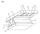
- FIG. 1 is a perspective view illustrating the construction of a discharge cell of a conventional three-electrode AC surface discharge type PDP.
- the three-electrode AC surface discharge type PDP includes a plurality of scan electrodes Y and a plurality of sustain electrodes Z which are formed on the bottom surface of an upper substrate 10, and an address electrode X formed on a lower substrate 18.
- the discharge cell of the PDP is formed at every crossing of the scan electrodes Y, the sustain electrodes Z and the address electrodes X and is arranged in a matrix form.
- Each of the scan electrode Y and the sustain electrode Z includes a transparent electrode 12, and a metal bus electrode 11 that has a line width smaller than the transparent electrode 12 and is disposed at one side of the transparent electrode.
- the metal bus electrode 11 is generally formed of a metal on the transparent electrode 12 and serves to reduce a voltage drop caused by the transparent electrode 12 having high resistance.
- On the bottom surface of the upper substrate 10 in which the scan electrodes Y and the sustain electrodes are disposed is laminated an upper dielectric layer 13 and a protective layer 14.
- the upper dielectric layer 13 is accumulated with a wall charge generated during plasma discharging.
- the protective layer 14 is adapted to prevent damages of the electrodes Y and Z and the upper dielectric layer 13 due to sputtering caused during plasma discharging, and improve efficiency of secondary electron emission.
- magnesium oxide (MgO) is generally used.
- the address electrodes X are formed on the lower substrate 18 in the direction that they intersect the scan electrodes Y and the sustain electrodes Z.
- a lower dielectric layer 17 and a diaphragm 15 are formed on the lower substrate 18.
- a phosphor layer 16 is formed on the surface of the lower dielectric layer 17 and the diaphragm 15. The phosphor layer 16 is excited with ultraviolet rays generated during the plasma discharging to generate any one visible light of red, green and blue lights.
- An inert mixed gas such as He+Xe, Ne+Xe or He+Xe+Ne for discharge is injected into the discharge space of the discharge cells provided between the upper and lower substrates 10 and 18 and the diaphragm 15.
- the aforementioned PDP driving method causes picture quality to vary with the order, weight and number of the sub fields.
- motion artifact large area flicker and a variation in the number of visible gray levels affect the picture quality.
- the motion artifact is caused by dynamic false contour noise and motion blurring.
- the dynamic false contour noise appears as a subfield-driven nonlinear emission pattern, and the motion blurring occurs when light is emitted from pixels for a period of time loner than one frame period.
- the dynamic false contour noise and the number of gray levels (the number of sub fields) or the large area flicker and the motion blurring have a complementary function relationship between them. For example, the motion blurring occurs when a frame frequency is increased in order to reduce flicker whereas sever flicker is generated when the frame frequency is decreased in order to reduce the motion blurring.
- FIG. 3 the vertical axis represents a weight given to each sub field and the horizontal axis represents time.
- the address period and the sustain period become short seriously as resolution is increased to WVGA, XGA or HD resolution so that it is impossible to arrange sub fields at 100Hz.
- Another method for reducing flicker is to make the optical center of the maximum brightness uniform in every frame when the optical center of the maximum brightness is varied with frames in a sub frame array in which weights are linearly arranged.
- this method requires a complicated algorithm and circuit for calculations for making the optical center uniform in every frame.
- an object of the present invention is to solve at least the problems and disadvantages of the background art.
- An object of the present invention is to provide a method and apparatus for driving a PDP with high resolution, which can reduce large area flicker and dynamic false contour noise.
- a method for driving a PDP including the steps of dividing two frame data items into three frame data items; and providing the divided frame data items to the PDP.
- An apparatus for driving a PDP includes a frame converting unit for dividing two frame data items into three frame data items; and a data providing unit for providing the divided data items to the PDP.
- a method for driving a PDP including the steps of: writing nth frame data (n is a natural number) in an odd-numbered line of a memory, writing (n+1)th frame data in an even-numbered line of the memory, generating a single insertion data item using data items read by addressing the odd-numbered line and even-numbered line of the memory, and inserting the insertion data between the nth frame data and the (n+1)th frame data; and providing the nth frame data, the (n+1)th frame data and the insertion data to the PDP.
- An apparatus for driving a PDP includes a memory including an odd-numbered line storing nth frame data (n is a natural number) and an even-numbered line storing (n+1)th frame data; a signal processor for generating a single insertion data item using data items read by addressing the odd-numbered line and even-numbered line of the memory and inserting the insertion data between the nth frame data and the (n+1)th frame data; and a data providing unit for providing the nth frame data, the (n+1)th frame data and the insertion data to the PDP.
- a method for driving a PDP including the steps of: storing (N-1)th frame data in a frame memory; separating main object image data and background image data from each of the stored (N-1)th frame data and Nth frame data currently input; generating object image data of an insertion frame using the main object image data of the (N-1)th frame data and the main object image data of the Nth frame data; generating background image data of the insertion frame using the background image data of the (N-1)th frame data and the background image data of the Nth frame data; and synthesizing the main object image data and background image data of the insertion frame to generate the insertion frame.
- the method and apparatus for driving a PDP according to the present invention can reduce large area flicker and dynamic false contour noise in a high-resolution PDP.
- FIG.1 is a perspective view illustrating the construction of a discharge cell of a conventional three-electrode AC surface discharge type PDP.
- FIG. 2 shows a conventional one frame containing eight time-divided sub fields.
- FIG. 3 shows a conventional 50Hz driving method.
- FIG. 4 is a diagram for explaining a method of driving a PDP according to a first embodiment of the present invention.
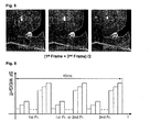
- FIG. 5 shows input frame data items and an image of mean value data inserted between the data items when the PDP driving method according to the first embodiment of the present invention is applied to an experimental image.
- FIG. 6 is a diagram for explaining a method of driving a PDP according to a second embodiment of the present invention.
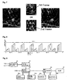
- FIG. 7 shows input frame data items and an image of copy data inserted between the data items when the PDP driving method according to the second embodiment of the present invention is applied to an experimental image.
- FIG. 8 is a diagram for explaining a method of driving a PDP according to another embodiment of the present invention.
- FIG. 9 is a block diagram of an apparatus for driving a PDP according to an embodiment of the present invention.
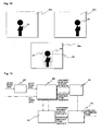
- FIG. 10 shows a process of generating an insertion frame after an object is detected according to a third embodiment of the present invention.
- FIG. 11 shows a process of dividing frame data into a main object and a background image.
- FIG. 12 shows a process of generating an object of an insertion frame.
- FIG. 13 is a block diagram showing a driving method for removing large area flicker of a PDP.
- FIG. 14 is a flow chart showing the driving method for removing large area flicker of a PDP.
- a method for driving a PDP according to a first embodiment of the present invention includes the steps of dividing two frame data items into three frame data items, and providing the divided frame data items to the PDP.
- the two frame data items are input at a frame frequency of 50Hz.
- the step of dividing the two frame data items includes a step of calculating a mean value of the two frame data items and a step of inserting the mean value between the two frame data items.
- the step of dividing the two frame data items includes a step of copying one of the two frame data items and a step of inserting the copied data between the two frame data items.
- the two frame data items include nth frame data and (n+1)th frame data (n is a natural number larger than 1), and the method further includes a step of mapping the (n+1)th frame data, the nth frame data and data inserted between the nth and (n+1)th frame data to a sub field sequence including eight sub fields.
- the two frame data items include nth frame data and (n+1)th frame data (n is a natural number larger than 1), and the method further includes a step of mapping the nth frame data to a sub field sequence including eight sub fields, a step of mapping data inserted between the nth frame data and the (n+1)th frame data to a sub field sequence including seven sub fields, and a step of mapping the (n+1)th frame data to a sub field sequence including nine sub fields.
- the two frame data items include nth frame data and (n+1)th frame data (n is a natural number larger than 1), and the method further includes a step of mapping the nth frame data to a sub field sequence including nine sub fields, a step of mapping data inserted between the nth frame data and the (n+1)th frame data to a sub field sequence including six sub fields, and a step of mapping the (n+1)th frame data to a sub field sequence including nine sub fields.
- a method for driving a PDP according to a modified one of the first embodiment of the present invention includes the steps of dividing five frame data items into six frame data items, and providing the divided frame data items to the PDP.
- the five frame data items are input at a frame frequency of 50Hz.
- the step of dividing the five frame data items includes a step of calculating a mean value of two frame data items temporally adjacent to each other among the five frame data items, and a step of inserting the mean value between the two frame data items.
- the step of dividing the five frame data items includes a step of copying one of two frame data items temporally adjacent to each other among the five frame data items, and a step of inserting the copied data between the two frame data items.
- An apparatus for driving a PDP includes a frame converting unit for dividing two frame data items into three frame data items, and a data providing unit for providing the divided data items to the PDP.
- the two frame data items are input at a frame frequency of 50Hz.
- the frame converting unit calculates a mean value of the two frame data items and inserts the mean value between the two frame data items.
- the frame converting unit copies one of the two frame data items and inserts the copied data between the two frame data items.
- the frame converting unit includes a synchronous detector for detecting a frame frequency, a signal processor for inserting one of the mean value and the copied data between the two frame data items when the frame frequency is 50Hz, and a controller for controlling the signal processor in response to the frame frequency.
- An apparatus for driving a PDP according to the modified one of the first embodiment of the present invention includes a frame converting unit for dividing five frame data items into six frame data items, and a data providing unit for providing the divided data items to the PDP.
- the five frame data items are input at a frame frequency of 50Hz.
- the frame converting unit calculates a mean value of two frame data items temporally adjacent to each other among the five frame data items and inserts the mean value between the two frame data items.
- the frame converting unit copies one of two frame data items temporally adjacent to each other and inserts the copied data between the two frame data items.
- the frame converting unit includes a synchronous detector for detecting a frame frequency, a signal processor for inserting one of the mean value and the copied data between the two frame data items when the frame frequency is 50Hz, and a controller for controlling the signal processor in response to the frame frequency.
- a method for driving a PDP includes the steps of writing nth frame data (n is a natural number) in an odd-numbered line of a memory, writing (n+1)th frame data in an even-numbered line of the memory, generating a single insertion data item using data items read by addressing the odd-numbered line and even-numbered line of the memory, and inserting the insertion data between the nth frame data and the (n+1)th frame data; and providing the nth frame data, the (n+1)th frame data and the insertion data to the PDP.
- the nth frame data and the (n+1)th frame data are input at a frame frequency of 50Hz.
- the insertion data is a copy of one of the odd-numbered line data and even-numbered line data of the memory.
- the insertion data is inserted between two frame data items adjacent to each other among five frame data items input at the frame frequency of 50Hz.
- An apparatus for driving a PDP includes a memory including an odd-numbered line storing nth frame data (n is a natural number) and an even-numbered line storing (n+1)th frame data; a signal processor for generating a single insertion data item using data items read by addressing the odd-numbered line and even-numbered line of the memory and inserting the insertion data between the nth frame data and the (n+1)th frame data; and a data providing unit for providing the nth frame data, the (n+1)th frame data and the insertion data to the PDP.
- the nth frame data and the (n+1)th frame data are input at a frame frequency of 50Hz.
- the signal processor copies one of the odd-numbered line data and even-numbered line data of the memory to generate the insertion data.
- the signal processor calculates a mean value of the odd-numbered line data and even-numbered line data of the memory to generate the insertion data.
- the signal processor inserts the insertion data between two frame data items adjacent to each other among five frame data items input at the frame frequency of 50Hz.
- the PDP driving method inserts new frame data corresponding to a mean value of two frame data items, which are input during two frame periods corresponding to 40ms, between the two frame data items when a frame frequency is 50Hz to drive a PDP at pseudo 75Hz.
- the frame data Fins inserted between the nth frame data and the (n+1)th frame data corresponds to the mean value of the temporally continuous two frame data items. That is, when the first frame data is 1 st Fr. and the second frame data is 2nd Fr., the inserted frame data Fins is calculated by (1st Fr. + 2nd Fr.)/2.
- the three frame data items including the frame data corresponding to the mean value are arranged for two frame periods when the PDP is driven at 50Hz, light is dispersed and thus large area flicker and dynamic false contour noise can be reduced and the address period and sustain period of the high-resolution PDP can be secured.
- the PDP driving method copies one of two frame data items that are input during two frame periods corresponding to 40ms at a frame frequency of 50Hz and inserts the copied data between the two frame data items to drive the PDP at pseudo 75Hz.
- the frame data inserted between the nth frame data and the (n+1)th frame data is identical to the nth frame data or the (n+1)th frame data. That is, during the two frame periods corresponding to 40ms, the nth frame data, the (n+1)th frame data or the nth frame data, and the (n+1)th frame data are sequentially provided to the PDP.
- the number of sub fields of the continuous three frame data items is 8-8-8, 8-7-9 or 9-6-9 considering the large area flicker and dynamic false contour noise.
- the following tables 1, 2 and 3 represent examples of the number of sub fields and weights when the PDP is driven at the pseudo 75Hz.
- each of the nth frame data Fn, the insertion data Fins (Fn or Fn+1) and the (n+1)th frame data Fn+1 is mapped to eight sub fields to which weights 1, 2, 4, 8, 16, 46, 46 and 47 are respectively given.
- the nth frame data Fn is mapped to eight sub fields to which weights 1, 2, 4, 8, 16, 46, 46, and 47 are given, and the insertion data Fins (Fn or Fn+1) is mapped to seven sub fields to which weights 1, 2, 4, 8, 16, 46 and 46 are given.
- the (n+1)th frame data Fn+1 are mapped to nine sub fields to which weights 1, 2, 4, 8, 16, 46, 46, 47 and 47 are given.
- the nth frame data Fn is mapped to nine sub fields to which weights 1, 2, 4, 8, 16, 23, 46, 46, and 47 are given, and the insertion data Fins (Fn or Fn+1) is mapped to six sub fields to which weights 2, 4, 8, 16, 46 and 46 are given.
- the (n+1)th frame data Fn+1 are mapped to nine sub fields to which weights 1, 2, 4, 8, 16, 24, 46, 47 and 47 are given.
- the weights can be varied with the composition of a discharge gas and a PDP model.
- each of the nth frame data Fn, the insertion data Fins and the (n+1)th frame data Fn+1 is mapped to eight sub fields to which weights 1, 4, 8, 16, 24, 25, 30 and 30 are respectively given.
- the nth frame data Fn is mapped to eight sub fields to which weights 1, 4, 8, 16, 24, 25, 30 and 30 are given, and the insertion data Fins (Fn or Fn+1) is mapped to seven sub fields to which weights 1, 4, 8, 16, 24, 25 and 30 are given.
- the (n+1)th frame data Fn+1 are mapped to nine sub fields to which weights 1, 4, 8, 16, 24, 25, 30, 30 and 30 are given.
- the nth frame data Fn is mapped to nine sub fields to which weights 1, 4, 8, 16, 24, 25, 30, 30 and 30 are given; and the insertion data Fins (Fn or Fn+1) is mapped to six sub fields to which weights 1, 4, 8, 16, 24 and 25.
- the (n+1)th frame data Fn+1 are mapped to nine sub fields to which weights 1, 4, 8, 16, 24, 25, 30, 30 and 30 are given.
- the weights can be varied with the composition of a discharge gas or a PDP model.
- a selective write/erase method can be applied to a cell selecting method and sub field arrangement.
- the selective write/erase method is more advantageous for high speed driving than a selective write method that selects an on-cell from a part of sub fields included in one frame and selects an off-cell from the other sub fields to thereby select only the on-cell and a selective erase method that selects only an off-cell from sub fields.
- the selective write-erase method is suitable for a PDP with high resolution and produces higher contrast and luminance.
- the number of sub fields of the continuous three frame data items is 8-8-8, 8-7-9 or 9-6-9 considering the large area flicker and dynamic false contour noise.
- the PDP driving method inserts data corresponding to a mean value of previous frame data and next frame data into a predetermined position during five frame periods corresponding to 100ms at the frame frequency of 50Hz or repeatedly provides one of the previous frame data and the next frame data to a PDP, to thereby drive the PDP at pseudo 60Hz.
- nth, (n+1)th, (n+2)th, (n+3)th and (n+4)th frame data items which are temporally continuous.
- Data corresponding to a mean value of two frame data items continuously input during 100ms or a copy of one of the two frame data items is inserted between the two frame data items.
- the inserted data can be a mean value of the second frame data 2nd Fr. and the third frame data 3rd Fr. or a copy of one of the second and third frame data items 2nd Fr. and 3rd Fr., and it is inserted between the second and third frame data items, as shown in FIG. 8.
- FIG. 9 is a block diagram of an apparatus for driving a PDP according to an embodiment of the present invention.
- the PDP driving apparatus includes a synchronous detector 91, a timing controller 92, a signal processor 93, frame memories 94a and 94b, a data arrangement unit 95, and buffers 96a and 96b.
- the synchronous detector 91 counts a vertical synchronous signal V and a horizontal synchronous signal H in response to a clock signal CLK to detect a frame frequency and provides the frame frequency to the timing controller 92.
- the signal processor 93 carries out error diffusion, gain control and dithering for digital video data RGB under the control of the timing controller 92, maps the digital video data to predetermined sub fields bit by bit, and then provides the mapped data to the data arrangement unit 95.
- the signal processor 93 stores the digital video data RGB in the frame memories 94a and 94b frame by frame under the control of the timing controller 92, and then reads the data stored in the frame memories 94a and 94b. Then, the signal processor 93 carries out error diffusion, gain control and dithering for the read data and maps the data to twelve sub fields to which weights 1, 2, 4, 8, 16, 32, 32, 32, 32, 32, 32, 32 and 32 are respectively given in a data input order.
- the signal processor 93 stores digital video data RGB of the nth frame Fn in the first frame memory 94a and stores digital video data RGB of the (n+1)th frame in the second frame memory 94b under the control of the timing controller 92. Then, the signal processor inserts data corresponding to a mean value of the nth and (n+1)th frame data items or a copy of one of the nth and (n+1)th frame data items between the nth and (n+1)th frame data items or inserts the mean data or copy data into a predetermined position in five frame data items continuously input as described in the aforementioned embodiments.
- the timing controller 92 controls the signal processor 93 in response to the frame frequency detected by the synchronous detector 91. Specifically, the timing controller 92 controls the signal processor 93 such that the signal processor 93 maps digital video data RGB to predetermined sub fields in the order of inputting the digital video data RGB when the frame frequency is 60Hz. When the frame frequency is 50Hz, the timing controller 92 controls the signal processor 93 such that the signal processor 93 inserts frame data between two continuous frame data items or insert frame data into a predetermined position in continuous five frame data items.
- the data arrangement unit 95 temporarily stores data received from the signal processor 93 in the buffers 96a and 96b, and then provides data read from the buffers 96a and 96b to a data driving circuit chip of a PDP 97.
- the method and apparatus for driving a PDP according to the first embodiment of the present invention can disperse light in a PDP with high resolution to reduce the large area flicker and dynamic false contour noise.
- the method and apparatus for driving a PDP write the nth frame data in odd-numbered lines of a memory and write the (n+1)th frame data in even-numbered lines of the memory, read odd-numbered line data of the memory and even-numbered line data that is the closest to the odd-numbered line data, and calculate a mean value of the read data items. Accordingly, a speed of calculating the mean value of the frame data items for reducing the large area flicker and dynamic false contour noise is reduced and thus the calculation can be efficiently carried out.
- a method for driving a PDP includes the steps of storing (N-1)th frame data in a frame memory; separating main object image data and background image data from each of the stored (N-1)th frame data and Nth frame data currently input; generating object image data of an insertion frame using the main object image data of the (N-1)th frame data and the main object image data of the Nth frame data; generating background image data of the insertion frame using the background image data of the (N-1)th frame data and the background image data of the Nth frame data; and synthesizing the main object image data and background image data of the insertion frame to generate the insertion frame.
- the driving method further includes a step of displaying the (N-1)th frame, a step of displaying the insertion frame, and a step of displaying the Nth frame.
- the number N is selected from 1 through 50.
- the frames are driven at a frequency of 75Hz.
- FIG. 10 shows a process of generating an insertion frame after objects are detected according to the third embodiment of the present invention.
- the insertion frame is generated by image reconstruction.
- main objects 304 and 305 are extracted from (N-1)th and Nth frames 301 and 302.
- a main object image of the insertion frame is reconstructed using the extracted main object images.
- a background image of the insertion frame is generated using background images of the (N-1)th and Nth frames 301 and 302.
- the insertion frame 303 is generated using the generated object image and background image of the insertion frame. That is, the third embodiment of the present invention generates a new image by combining the extracted data in order to make the insertion frame for up-converting 50Hz to 75Hz, distinguished from a prior art that simply combines two data items to insert a blurred image. When the newly generated frame is inserted, a smooth motion can be represented and picture quality can be improved.
- FIG. 11 shows a process of dividing frame data into a main object and a background image
- FIG. 12 shows a process of generating an object of an insertion frame.
- an input frame 301 is divided into a main object image 301a and a background image 301b.
- the (N-1)th object image 301a and the Nth object image 302a respectively separated from the (N-1)th frame and the Nth frame are combined to generate an object image 303a of the insertion frame.
- a background image 301b of the insertion frame is generated by averaging background image data of the (N-1)th frame and background image data of the Nth frame.
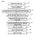
- FIG. 13 is a block diagram showing a driving method for removing large area flicker of a PDP
- FIG. 14 is a flow chart showing the driving method for removing large area flicker of a PDP. The process of generating the insertion frame will now be explained with reference to FIGS. 13 and 14.
- the input (N-1)th frame data is stored in a frame memory 601 in the step S701.
- the (N-1)th frame data and the Nth frame data are input, and main object image data of the (N-1)th frame data and main object image data of the Nth frame data are detected in the step S702.
- the detected main object image data and background image data are extracted in the step S703.
- the conventional gradient watershed algorithm or region growing image processing algorithm is preferably used as a method of detecting the main object image data.
- the main object image data and background image data are separated from each of the (N-1)th frame data and the Nth frame data.
- a main object image of the insertion frame is generated in the step S704.
- the main object image data of the (N-1)th frame and the main object image data of the Nth frame, separated in the step S703, are combined by the following method.
- the main object image data of the Nth frame is compared with the main object image data of the (N-1)th frame.
- a common value among the main object image data values of the two frames is used as it is for constructing the main object image of the insertion frame.
- a difference value between main object image data values of the two frames is not used. Instead an intermediate value of the corresponding main object image data values of the two frames is used for constructing the main object image of the insertion frame.
- the reconstructed data generates the main object image of the insertion frame as shown in FIG. 12.
- the background image of the insertion frame is generated.
- a method of generating the background image of the insertion frame is different from the method of generating the main object image of the insertion frame in the step S704. That is, the background image data of the insertion frame is generated using the background image data of the (N-1)th frame and the background image data of the Nth frame. Since there is a little difference between the background image data of the (N-1)th frame and the background image data of the Nth frame, a value obtained by adding up the two background image data values and dividing the added value by half can be used or a blurred image obtained by simply adding up the two background image data items can be used.
- the insertion frame is generated by synthesizing the main object image data of the insertion frame, generated in the step S704, and the background image data of the insertion frame, generated in the step S705. That is, the object image and background image of the insertion frame are synthesized to accomplish one insertion frame image.
- the generated insertion frame is inserted between the (N-1)th frame and the Nth frame.
- the number N can be selected from odd numbers. That is, the first and second frames generate one insertion frame and the third and fourth frames generate one insertion frame. This is repeated until the forty-ninth and fiftieth frames generate one insertion frame. In this manner, twenty-five insertion frames are generated. Accordingly, the total number of frames can be 75.
- the number N is not limited to odd numbers and it can be an even number.
- the 75Hz up-conversion is an example and any up-conversion can be achieved. That is, it is possible to generate insertion frames based on a desired number of frames.
- the PDP when a PDP is driven in W-VGA, twenty-four sub fields are used for two frames because twelve sub fields are used for one frame. When these two frames are divided into three frames, the PDP can be driven using SW8-SW8-SW8/SW8-SW7-SW9/SW9-SW6-SW9 method or SWSE-combined8-8-8/8-7-9/9-6-9 method.
- the insertion frame is generated using the method provided by the present invention and then an image is represented with eight sub fields.
- the present invention can remove large area flicker generated when a 50Hz video signal such as PAL or SECAM is input in a PDP or a digital micro-mirror device panel. Furthermore, the present invention can be applied to light-emitting devices such as a digital micro-mirror device in addition to the PDP.
Landscapes
- Engineering & Computer Science (AREA)
- Physics & Mathematics (AREA)
- Computer Hardware Design (AREA)
- General Physics & Mathematics (AREA)
- Theoretical Computer Science (AREA)
- Control Of Indicators Other Than Cathode Ray Tubes (AREA)
- Control Of Gas Discharge Display Tubes (AREA)
- Transforming Electric Information Into Light Information (AREA)
Priority Applications (1)
| Application Number | Priority Date | Filing Date | Title |
|---|---|---|---|
| EP08150560A EP1921595A3 (de) | 2003-09-30 | 2004-09-22 | Verfahren und Vorrichtung zur Ansteuerung einer Plasmaanzeigetafel |
Applications Claiming Priority (6)
| Application Number | Priority Date | Filing Date | Title |
|---|---|---|---|
| KR10-2003-0067935A KR100515650B1 (ko) | 2003-09-30 | 2003-09-30 | 플라즈마 디스플레이 패널의 광역 플리커 제거를 위한비디오 화상 처리 방법 |
| KR2003067935 | 2003-09-30 | ||
| KR1020030089892A KR100583315B1 (ko) | 2003-12-10 | 2003-12-10 | 플라즈마 디스플레이 패널의 구동방법 및 장치 |
| KR2003089892 | 2003-12-10 | ||
| KR1020030089891A KR20050056828A (ko) | 2003-12-10 | 2003-12-10 | 플라즈마 디스플레이 패널의 구동방법 및 장치 |
| KR2003089891 | 2003-12-10 |
Related Child Applications (1)
| Application Number | Title | Priority Date | Filing Date |
|---|---|---|---|
| EP08150560A Division EP1921595A3 (de) | 2003-09-30 | 2004-09-22 | Verfahren und Vorrichtung zur Ansteuerung einer Plasmaanzeigetafel |
Publications (2)
| Publication Number | Publication Date |
|---|---|
| EP1521233A2 true EP1521233A2 (de) | 2005-04-06 |
| EP1521233A3 EP1521233A3 (de) | 2006-06-14 |
Family
ID=34317270
Family Applications (2)
| Application Number | Title | Priority Date | Filing Date |
|---|---|---|---|
| EP08150560A Withdrawn EP1921595A3 (de) | 2003-09-30 | 2004-09-22 | Verfahren und Vorrichtung zur Ansteuerung einer Plasmaanzeigetafel |
| EP04022519A Withdrawn EP1521233A3 (de) | 2003-09-30 | 2004-09-22 | Verfahren und Einrichtung zum Steuern einer Plasmaanzeigetafel |
Family Applications Before (1)
| Application Number | Title | Priority Date | Filing Date |
|---|---|---|---|
| EP08150560A Withdrawn EP1921595A3 (de) | 2003-09-30 | 2004-09-22 | Verfahren und Vorrichtung zur Ansteuerung einer Plasmaanzeigetafel |
Country Status (4)
| Country | Link |
|---|---|
| US (2) | US7474279B2 (de) |
| EP (2) | EP1921595A3 (de) |
| JP (1) | JP2005107541A (de) |
| CN (1) | CN100424737C (de) |
Cited By (1)
| Publication number | Priority date | Publication date | Assignee | Title |
|---|---|---|---|---|
| EP2198419A4 (de) * | 2007-10-17 | 2011-01-05 | Lg Electronics Inc | Plasmaanzeigevorrichtung |
Families Citing this family (8)
| Publication number | Priority date | Publication date | Assignee | Title |
|---|---|---|---|---|
| KR100791481B1 (ko) * | 2006-02-13 | 2008-01-03 | 엘지전자 주식회사 | 디스플레이 장치 및 제어 방법 |
| US9620038B2 (en) * | 2007-08-08 | 2017-04-11 | Landmark Screens, Llc | Method for displaying a single image for diagnostic purpose without interrupting an observer's perception of the display of a sequence of images |
| US9342266B2 (en) | 2007-08-08 | 2016-05-17 | Landmark Screens, Llc | Apparatus for dynamically circumventing faults in the light emitting diodes (LEDs) of a pixel in a graphical display |
| US9536463B2 (en) | 2007-08-08 | 2017-01-03 | Landmark Screens, Llc | Method for fault-healing in a light emitting diode (LED) based display |
| US9779644B2 (en) | 2007-08-08 | 2017-10-03 | Landmark Screens, Llc | Method for computing drive currents for a plurality of LEDs in a pixel of a signboard to achieve a desired color at a desired luminous intensity |
| KR20090102066A (ko) * | 2008-03-25 | 2009-09-30 | 삼성에스디아이 주식회사 | 플라즈마 표시장치의 구동 방법 및 구동 장치 |
| KR101497651B1 (ko) * | 2008-09-03 | 2015-03-06 | 삼성디스플레이 주식회사 | 표시 장치 및 이의 구동 방법 |
| KR102234512B1 (ko) * | 2014-05-21 | 2021-04-01 | 삼성디스플레이 주식회사 | 표시 장치, 표시 장치를 포함하는 전자 기기 및 그의 구동 방법 |
Family Cites Families (24)
| Publication number | Priority date | Publication date | Assignee | Title |
|---|---|---|---|---|
| JPS59185485A (ja) | 1983-04-07 | 1984-10-22 | Hitachi Ltd | テレビジヨン方式 |
| DE3408061A1 (de) * | 1984-03-05 | 1985-09-05 | ANT Nachrichtentechnik GmbH, 7150 Backnang | Verfahren zur bewegungsadaptiven interpolation von fernsehbildsequenzen und anwendungen dieses verfahrens |
| US6331862B1 (en) * | 1988-07-06 | 2001-12-18 | Lg Philips Lcd Co., Ltd. | Image expansion display and driver |
| JPH05127612A (ja) * | 1991-11-05 | 1993-05-25 | Nippon Hoso Kyokai <Nhk> | 中間調画像表示方法 |
| US5481275A (en) * | 1992-11-02 | 1996-01-02 | The 3Do Company | Resolution enhancement for video display using multi-line interpolation |
| US5835952A (en) * | 1993-07-14 | 1998-11-10 | Matsushita Electric Industrial Co., Ltd. | Monolithic image data memory system and access method that utilizes multiple banks to hide precharge time |
| IT1261633B (it) | 1993-10-26 | 1996-05-23 | Seleco Spa | Metodo per la conversione della frequenza di ripetizione delle trame di un segnale video da 50 hz a 75 hz con compensazione del movimento eapparecchiatura per la implementazione di tale metodo. |
| US5805126A (en) | 1994-05-05 | 1998-09-08 | Neomagic Corporation | Display system with highly linear, flicker-free gray scales using high framecounts |
| US5531224A (en) | 1994-11-23 | 1996-07-02 | General Electric Company | Framem interpolator for increasing apparent acoustic frame rate in ultrasound imaging |
| US6222589B1 (en) * | 1996-08-08 | 2001-04-24 | Yves C. Faroudja | Displaying video on high-resolution computer-type monitors substantially without motion discontinuities |
| JPH10171401A (ja) * | 1996-12-11 | 1998-06-26 | Fujitsu Ltd | 階調表示方法 |
| JPH10257435A (ja) * | 1997-03-10 | 1998-09-25 | Sony Corp | 映像信号再生装置及び映像信号再生方法 |
| JPH10304281A (ja) * | 1997-05-02 | 1998-11-13 | Fujitsu Ltd | 階調表示方法 |
| JP3403635B2 (ja) * | 1998-03-26 | 2003-05-06 | 富士通株式会社 | 表示装置および該表示装置の駆動方法 |
| JP3595745B2 (ja) * | 1999-01-29 | 2004-12-02 | キヤノン株式会社 | 画像処理装置 |
| JP3837690B2 (ja) | 1999-12-03 | 2006-10-25 | パイオニア株式会社 | 映像信号処理装置 |
| JP2002123213A (ja) | 2000-10-18 | 2002-04-26 | Fujitsu Ltd | 画像表示のためのデータ変換方法 |
| JP2002229505A (ja) | 2001-01-31 | 2002-08-16 | Nec Corp | 表示装置 |
| DE60139598D1 (de) * | 2001-02-10 | 2009-10-01 | Thomson Licensing | Stereoskopische Plasmaanzeige |
| JP4517046B2 (ja) | 2001-07-30 | 2010-08-04 | 三星エスディアイ株式会社 | プラズマディスプレイ用の動き補正されたアップコンバージョン |
| JP3861113B2 (ja) | 2001-08-30 | 2006-12-20 | 株式会社日立プラズマパテントライセンシング | 画像表示方法 |
| US6657609B2 (en) | 2001-09-28 | 2003-12-02 | Koninklijke Philips Electronics N.V. | Liquid crystal displays with reduced flicker |
| EP1359749A1 (de) * | 2002-05-04 | 2003-11-05 | Deutsche Thomson-Brandt Gmbh | Vielfrequenz-Anzeigemodus für eine Plasma-Anzeigefläche |
| JP2004093717A (ja) | 2002-08-30 | 2004-03-25 | Hitachi Ltd | 液晶表示装置 |
-
2004
- 2004-09-22 EP EP08150560A patent/EP1921595A3/de not_active Withdrawn
- 2004-09-22 EP EP04022519A patent/EP1521233A3/de not_active Withdrawn
- 2004-09-29 CN CNB2004100806461A patent/CN100424737C/zh not_active Expired - Fee Related
- 2004-09-29 US US10/952,473 patent/US7474279B2/en not_active Expired - Fee Related
- 2004-09-30 JP JP2004285847A patent/JP2005107541A/ja not_active Withdrawn
-
2007
- 2007-09-18 US US11/856,955 patent/US7460139B2/en not_active Expired - Fee Related
Cited By (1)
| Publication number | Priority date | Publication date | Assignee | Title |
|---|---|---|---|---|
| EP2198419A4 (de) * | 2007-10-17 | 2011-01-05 | Lg Electronics Inc | Plasmaanzeigevorrichtung |
Also Published As
| Publication number | Publication date |
|---|---|
| US20050068268A1 (en) | 2005-03-31 |
| EP1921595A3 (de) | 2008-08-06 |
| JP2005107541A (ja) | 2005-04-21 |
| US20080007487A1 (en) | 2008-01-10 |
| CN1604160A (zh) | 2005-04-06 |
| EP1921595A2 (de) | 2008-05-14 |
| US7474279B2 (en) | 2009-01-06 |
| CN100424737C (zh) | 2008-10-08 |
| US7460139B2 (en) | 2008-12-02 |
| EP1521233A3 (de) | 2006-06-14 |
Similar Documents
| Publication | Publication Date | Title |
|---|---|---|
| US7460139B2 (en) | Method and apparatus of driving a plasma display panel | |
| US6097358A (en) | AC plasma display with precise relationships in regards to order and value of the weighted luminance of sub-fields with in the sub-groups and erase addressing in all address periods | |
| JP2903984B2 (ja) | ディスプレイ装置の駆動方法 | |
| US6018329A (en) | Driving system for a plasma display panel | |
| JP3430593B2 (ja) | ディスプレイ装置の駆動方法 | |
| US7256794B2 (en) | Method and apparatus for processing video data of display device | |
| JP2005321442A (ja) | ディスプレイ装置のディザ処理回路 | |
| JP2001154630A (ja) | ディスプレイ装置のディザ処理回路 | |
| JP2000035774A (ja) | 表示装置 | |
| JPH10282929A (ja) | 階調表示方法 | |
| CN101101725B (zh) | 等离子显示装置、等离子显示装置用驱动电路和等离子显示装置的图像显示方法 | |
| KR20040010768A (ko) | 화상표시장치 및 그 구동방법 | |
| JP2001222250A (ja) | ディスプレイパネルの駆動方法 | |
| CN1691104B (zh) | 等离子显示设备及其驱动方法 | |
| US7109950B2 (en) | Display apparatus | |
| JP2009008738A (ja) | 表示装置及び表示方法 | |
| KR100583315B1 (ko) | 플라즈마 디스플레이 패널의 구동방법 및 장치 | |
| KR100578917B1 (ko) | 플라즈마 디스플레이 패널의 구동 장치, 플라즈마디스플레이 패널의 화상 처리 방법 및 플라즈마디스플레이 패널 | |
| KR100615177B1 (ko) | 효율적으로 계조 데이터가 표시되는 평판 표시 패널의구동 방법 | |
| KR20050056828A (ko) | 플라즈마 디스플레이 패널의 구동방법 및 장치 | |
| US20080122738A1 (en) | Video Signal Processing Apparatus and Video Signal Processing Method | |
| KR100547980B1 (ko) | 플라즈마 디스플레이 패널의 구동방법 및 장치 | |
| KR100556695B1 (ko) | 플라즈마 디스플레이 패널의 어드레스 방법 및 장치 | |
| JP4048089B2 (ja) | 画像表示装置 | |
| KR100581883B1 (ko) | 패널구동방법 및 장치 |
Legal Events
| Date | Code | Title | Description |
|---|---|---|---|
| PUAI | Public reference made under article 153(3) epc to a published international application that has entered the european phase |
Free format text: ORIGINAL CODE: 0009012 |
|
| AK | Designated contracting states |
Kind code of ref document: A2 Designated state(s): AT BE BG CH CY CZ DE DK EE ES FI FR GB GR HU IE IT LI LU MC NL PL PT RO SE SI SK TR |
|
| AX | Request for extension of the european patent |
Extension state: AL HR LT LV MK |
|
| 17P | Request for examination filed |
Effective date: 20060301 |
|
| PUAL | Search report despatched |
Free format text: ORIGINAL CODE: 0009013 |
|
| AK | Designated contracting states |
Kind code of ref document: A3 Designated state(s): AT BE BG CH CY CZ DE DK EE ES FI FR GB GR HU IE IT LI LU MC NL PL PT RO SE SI SK TR |
|
| AX | Request for extension of the european patent |
Extension state: AL HR LT LV MK |
|
| 17Q | First examination report despatched |
Effective date: 20070122 |
|
| AKX | Designation fees paid |
Designated state(s): DE FR GB NL |
|
| STAA | Information on the status of an ep patent application or granted ep patent |
Free format text: STATUS: THE APPLICATION IS DEEMED TO BE WITHDRAWN |
|
| 18D | Application deemed to be withdrawn |
Effective date: 20080129 |