EP1521201B1 - Appareil terminal mobile - Google Patents
Appareil terminal mobile Download PDFInfo
- Publication number
- EP1521201B1 EP1521201B1 EP04023341A EP04023341A EP1521201B1 EP 1521201 B1 EP1521201 B1 EP 1521201B1 EP 04023341 A EP04023341 A EP 04023341A EP 04023341 A EP04023341 A EP 04023341A EP 1521201 B1 EP1521201 B1 EP 1521201B1
- Authority
- EP
- European Patent Office
- Prior art keywords
- communication
- contact
- information
- writer
- mobile telephone
- Prior art date
- Legal status (The legal status is an assumption and is not a legal conclusion. Google has not performed a legal analysis and makes no representation as to the accuracy of the status listed.)
- Expired - Fee Related
Links
- 238000004891 communication Methods 0.000 claims description 187
- 230000008859 change Effects 0.000 claims description 4
- 230000006870 function Effects 0.000 description 11
- 230000007704 transition Effects 0.000 description 7
- 230000004913 activation Effects 0.000 description 6
- 230000005540 biological transmission Effects 0.000 description 6
- 238000012545 processing Methods 0.000 description 6
- 230000000694 effects Effects 0.000 description 5
- 238000000034 method Methods 0.000 description 5
- 230000005674 electromagnetic induction Effects 0.000 description 4
- 230000008569 process Effects 0.000 description 4
- 230000000737 periodic effect Effects 0.000 description 3
- 230000003213 activating effect Effects 0.000 description 2
- 238000013500 data storage Methods 0.000 description 2
- 230000010365 information processing Effects 0.000 description 2
- 230000009471 action Effects 0.000 description 1
- 238000013459 approach Methods 0.000 description 1
- 238000013461 design Methods 0.000 description 1
- 230000005670 electromagnetic radiation Effects 0.000 description 1
- 238000007726 management method Methods 0.000 description 1
- 238000012986 modification Methods 0.000 description 1
- 230000004048 modification Effects 0.000 description 1
- 230000001737 promoting effect Effects 0.000 description 1
- 230000003245 working effect Effects 0.000 description 1
Images

Classifications
-
- H—ELECTRICITY
- H04—ELECTRIC COMMUNICATION TECHNIQUE
- H04B—TRANSMISSION
- H04B5/00—Near-field transmission systems, e.g. inductive or capacitive transmission systems
- H04B5/40—Near-field transmission systems, e.g. inductive or capacitive transmission systems characterised by components specially adapted for near-field transmission
- H04B5/48—Transceivers
-
- G—PHYSICS
- G06—COMPUTING; CALCULATING OR COUNTING
- G06K—GRAPHICAL DATA READING; PRESENTATION OF DATA; RECORD CARRIERS; HANDLING RECORD CARRIERS
- G06K7/00—Methods or arrangements for sensing record carriers, e.g. for reading patterns
- G06K7/0008—General problems related to the reading of electronic memory record carriers, independent of its reading method, e.g. power transfer
-
- G—PHYSICS
- G06—COMPUTING; CALCULATING OR COUNTING
- G06K—GRAPHICAL DATA READING; PRESENTATION OF DATA; RECORD CARRIERS; HANDLING RECORD CARRIERS
- G06K17/00—Methods or arrangements for effecting co-operative working between equipments covered by two or more of main groups G06K1/00 - G06K15/00, e.g. automatic card files incorporating conveying and reading operations
-
- G—PHYSICS
- G06—COMPUTING; CALCULATING OR COUNTING
- G06Q—INFORMATION AND COMMUNICATION TECHNOLOGY [ICT] SPECIALLY ADAPTED FOR ADMINISTRATIVE, COMMERCIAL, FINANCIAL, MANAGERIAL OR SUPERVISORY PURPOSES; SYSTEMS OR METHODS SPECIALLY ADAPTED FOR ADMINISTRATIVE, COMMERCIAL, FINANCIAL, MANAGERIAL OR SUPERVISORY PURPOSES, NOT OTHERWISE PROVIDED FOR
- G06Q20/00—Payment architectures, schemes or protocols
- G06Q20/30—Payment architectures, schemes or protocols characterised by the use of specific devices or networks
- G06Q20/34—Payment architectures, schemes or protocols characterised by the use of specific devices or networks using cards, e.g. integrated circuit [IC] cards or magnetic cards
- G06Q20/341—Active cards, i.e. cards including their own processing means, e.g. including an IC or chip
-
- G—PHYSICS
- G06—COMPUTING; CALCULATING OR COUNTING
- G06Q—INFORMATION AND COMMUNICATION TECHNOLOGY [ICT] SPECIALLY ADAPTED FOR ADMINISTRATIVE, COMMERCIAL, FINANCIAL, MANAGERIAL OR SUPERVISORY PURPOSES; SYSTEMS OR METHODS SPECIALLY ADAPTED FOR ADMINISTRATIVE, COMMERCIAL, FINANCIAL, MANAGERIAL OR SUPERVISORY PURPOSES, NOT OTHERWISE PROVIDED FOR
- G06Q20/00—Payment architectures, schemes or protocols
- G06Q20/30—Payment architectures, schemes or protocols characterised by the use of specific devices or networks
- G06Q20/34—Payment architectures, schemes or protocols characterised by the use of specific devices or networks using cards, e.g. integrated circuit [IC] cards or magnetic cards
- G06Q20/357—Cards having a plurality of specified features
-
- G—PHYSICS
- G07—CHECKING-DEVICES
- G07F—COIN-FREED OR LIKE APPARATUS
- G07F7/00—Mechanisms actuated by objects other than coins to free or to actuate vending, hiring, coin or paper currency dispensing or refunding apparatus
- G07F7/08—Mechanisms actuated by objects other than coins to free or to actuate vending, hiring, coin or paper currency dispensing or refunding apparatus by coded identity card or credit card or other personal identification means
- G07F7/10—Mechanisms actuated by objects other than coins to free or to actuate vending, hiring, coin or paper currency dispensing or refunding apparatus by coded identity card or credit card or other personal identification means together with a coded signal, e.g. in the form of personal identification information, like personal identification number [PIN] or biometric data
- G07F7/1008—Active credit-cards provided with means to personalise their use, e.g. with PIN-introduction/comparison system
-
- H—ELECTRICITY
- H04—ELECTRIC COMMUNICATION TECHNIQUE
- H04B—TRANSMISSION
- H04B5/00—Near-field transmission systems, e.g. inductive or capacitive transmission systems
-
- H—ELECTRICITY
- H04—ELECTRIC COMMUNICATION TECHNIQUE
- H04M—TELEPHONIC COMMUNICATION
- H04M1/00—Substation equipment, e.g. for use by subscribers
- H04M1/72—Mobile telephones; Cordless telephones, i.e. devices for establishing wireless links to base stations without route selection
- H04M1/724—User interfaces specially adapted for cordless or mobile telephones
- H04M1/72403—User interfaces specially adapted for cordless or mobile telephones with means for local support of applications that increase the functionality
- H04M1/72406—User interfaces specially adapted for cordless or mobile telephones with means for local support of applications that increase the functionality by software upgrading or downloading
-
- H—ELECTRICITY
- H04—ELECTRIC COMMUNICATION TECHNIQUE
- H04M—TELEPHONIC COMMUNICATION
- H04M1/00—Substation equipment, e.g. for use by subscribers
- H04M1/72—Mobile telephones; Cordless telephones, i.e. devices for establishing wireless links to base stations without route selection
- H04M1/724—User interfaces specially adapted for cordless or mobile telephones
- H04M1/72403—User interfaces specially adapted for cordless or mobile telephones with means for local support of applications that increase the functionality
- H04M1/72409—User interfaces specially adapted for cordless or mobile telephones with means for local support of applications that increase the functionality by interfacing with external accessories
- H04M1/72412—User interfaces specially adapted for cordless or mobile telephones with means for local support of applications that increase the functionality by interfacing with external accessories using two-way short-range wireless interfaces
Definitions
- the present invention relates to mobile terminal apparatuses suited to utilization as mobile telephones provided with non-contact ICs (IC: Integrated Circuit), PHS telephones (Personal Handyphone System), or PDA apparatuses (Personal Digital Assistant) etc.
- IC Integrated Circuit
- PHS telephones Personal Handyphone System
- PDA apparatuses Personal Digital Assistant
- a user operates a mobile terminal so as to communicate with an advance ticket sales host computer so as to purchase desired tickets such as express tickets, tickets for a reserved seat, and periodic commuter tickets in advance.
- the advance ticket sales host computer then connects to a host computer of a bank or credit company specified by the user. Settlement processing is then carried out through communication with the host computer of the bank or credit company specified by the user while the advance ticket purchase is taking place.
- the advance ticket sales host computer sends purchasing information indicating the ticket purchased by the user to the mobile terminal of the user.
- the mobile terminal of the user stores this purchasing information in an IC module provided at the mobile terminal.
- automatic ticketing is carried out through communication with the automatic ticketing machine based on the purchasing information stored in the IC module.
- patent document 2 Japanese Patent Application Publication No. 2002-197419 (patent document 2), there is disclosed an information processing apparatus and data communication method for notifying users of content of each process by providing light-emitting diodes on the four corners of a non-contact IC card and controlling generation of light by the light-emitting diodes according to the content of communication with the reader/writer.
- Patent Document 3 a route guidance system for finding routes using a non-contact IC card provided in a mobile information terminal is disclosed in Japanese Patent Application Publication No. 2002-298169 (Patent Document 3).
- this route guidance system communication is carried out between a non-contact IC card provided in a mobile information terminal and an automatic ticketing machine while a user passes through the automatic ticketing machine and information regarding stations entered is sent from the automatic ticketing machine to the mobile information terminal.
- the mobile information terminal invites input of the destination etc. of the user.
- destination information, entered station information, and information for the time of entering etc. is sent to a route retrieval server via a base station.
- the route retrieval server retrieves routes for the user based on this information and sends route retrieval results to the mobile information terminal of the user via the base station.
- WO 01/99066 A concerns a set for automatically reading an information carried by data storage means adapted to be read, comprising a reading module connected to a mobile telephone terminal, the mobile telephone terminal comprising means for triggering reading by said module of the information carried by the data storage means, the reading module including means for transmitting to the mobile telephone terminal a signal bearing the read information.
- the information carried by the storage means comprises a code identifying a mobile element whereon said storage means are recorded and the mobile telephone terminal comprises means for triggering and managing a sequence of operations comprising successively: reading said code by the reading module; transmitting said code, by said telephone terminal, to a remote management server.
- US-B1-6615057 relates to an arrangement for communication of subscriber identity module related data in a wireless communication system.
- the arrangement comprises a wireless communication terminal with a subscriber identity unit which includes a subscriber identity module, to which a subscriber identity is assigned.
- the subscriber identity unit is arranged to communicate the subscriber identity module related data, such as, for example the subscriber identity, to the terminal over a local wireless communication link.
- the mobile terminal apparatus is capable of smoothly activating and executing applications designated by an external communication means using a new communication protocol capable of flexible communication between non-contact communication means and internal control means.
- the mobile terminal apparatus of the present invention comprises internal control means for controlling execution of prescribed applications, and non-contact communication means equipped with a first communication state for carrying out non-contact communication with external communication apparatuses over short distances and a second communication state for carrying out communication with the control means and being capable of moving communication state between the first communication state and the second communication state, for carrying out communication between the external communication apparatus or the internal control means.
- the mobile terminal apparatus of the present invention has a flexible communication protocol capable of communication between the non-contact communication means and the internal control means even in cases where the non-contact communication means is communicating with the external communication apparatus, using a concept referred to as "interrupts".
- the non-contact communication means receives at least interrupt information and execution application information indicating the application to be executed sent from the external communication apparatus in non-contact communication with the external communication apparatus using receiving means.
- the non-contact communication means adopts a state where communication with the internal control means is possible by giving notification to the internal control means to the effect that interrupt information has been received using notification means and making a transition from the first communication state to the second communication state using communication state changing means.
- control means carries out communication with the non-contact communication means with the communication state put to the second communication state by the communication state changing means, execution application information received by the receiving means is taken in, and control of execution of applications corresponding to the taken-in execution application information takes place.
- control means can smoothly control activation and execution of applications designated by external communication means using the flexible communication protocol enabling communication with the internal control means while the non-contact communication means is communicating with the external communication apparatus.
- applications at the mobile terminal apparatus can be automatically executed by sending applications to be executed to the mobile terminal apparatus by pushing from the external communication apparatus.
- the present invention is applicable to a mobile telephone for transmitting and receiving audio data and packet data etc. in a wireless manner to and from a wireless base station via an antenna.
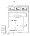
- the mobile telephone of the first invention of the present invention is comprised of a non-contact IC 2 (IC: Integrated Circuit) for carrying out short-range communication in a non-contact manner with an external reader/writer 1 shown in FIG. 1 , an application manager controller 3 for taking in information (execution application information) specifying an application sent from the external reader 1 via the non-contact IC 2 and controlling execution, and application memory 4 for storing various application programs such as LED application programs (LED: Light Emitting Diode), WEB browser application programs, and application programs (sound/vibration) for audio control and vibration functions.
- LED application programs LED: Light Emitting Diode
- WEB browser application programs and application programs (sound/vibration) for audio control and vibration functions.
- blocks such as a communication function, audio/image processing function, and display function etc. the mobile telephone is equipped with are not shown but it is wished to be understood that these will naturally be provided.
- the application manager controller 3 has an operating system function (OS), disc driver function, and application manager function as shown in FIG. 1 .
- OS operating system function
- disc driver function disc driver function
- application manager function As shown in FIG. 1 , the application manager controller 3 has an operating system function (OS), disc driver function, and application manager function as shown in FIG. 1 .
- OS operating system function
- disc driver function disc driver function
- application manager function As shown in FIG. 1 , the application manager controller 3 has an operating system function (OS), disc driver function, and application manager function as shown in FIG. 1 .
- OS operating system function
- disc driver function disc driver function
- application manager function application manager function
- the non-contact IC 2 is comprised of an antenna 11 for transmitting and receiving information in short-distance communication with the external reader/writer 1, an RF unit 12 (RF: Radio Frequency) for subjecting information transmitted and received via the antenna 11 to information processing, volatile memory 13 (buffer memory) temporarily written with transmitted and received information, and a control unit 14 for controlling the overall operation of the non-contact IC 2.
- RF Radio Frequency
- the non-contact IC 2 is comprised of a transmission terminal 15 (Tx terminal) provided with information transmitted via the antenna 11 and the RF unit 12, a receive terminal 16 (Rx terminal) outputting information received via the antenna 11 and the RF unit 12, and an earth connection terminal 17 (GND terminal).
- Tx terminal transmission terminal 15
- Rx terminal receive terminal 16
- GND terminal earth connection terminal 17
- the non-contact terminal IC 2 is comprised of a terminal I 18 (IB03 terminal) for switching between a high level (H) and low level (L) voltage applied according to the communication state under the control of the control unit 14, a terminal V 19 (VRO terminal) and terminal P 20 (PPO_ON terminal).
- IB03 terminal for switching between a high level (H) and low level (L) voltage applied according to the communication state under the control of the control unit 14, a terminal V 19 (VRO terminal) and terminal P 20 (PPO_ON terminal).
- the voltage applied to the terminal I 16 is switched from “H” to “L” under the control of the control unit 14. Further, when communication with the external reader/writer 1 commences, the voltage applied to the terminal 19 (VRO terminal) is switched over from “H” to “L” under the control of the control unit 14. Also, when communication with the external reader/writer 1 commences, the voltage applied to the terminal P 20 (PPO_ON) is switched from “H” to “L” under the control of the control unit 14.
- the non-contact IC 2 operates due to electrical power supplied from the external reader/writer 1 in the event of communication with the external reader/writer 1, and operates due to electrical power from the application manager controller 3 in the event of communication with the application manager controller 3.
- the non-contact IC 2 In the event that a supply of electrical power is received from the external reader/writer 1, the non-contact IC 2 carries out communication based on the clock frequency of the external reader/writer 1.
- the non-contact IC 2 carries out communication based on the clock frequency of the application manager controller 3 in the event that a supply of electrical power is received from the application manager controller 3.
- the clock frequency in the event of communication with the external reader/writer 1 is different from the clock frequency in the event of communication with the application manager controller 3. It is therefore not possible for the non-contact IC 2 to communicate with the application manager controller 3 when communicating with the external reader/writer 1 and conversely it is not possible for communication with the external reader/writer 1 to take place during communication with the application manager controller 3.
- the non-contact IC 2 exerts control so that the voltage applied to the terminal P 20 is a low level (L) using the control unit 14.
- the non-contact IC 2 exerts control so that the voltage applied to the terminal V 19 is a low level (L) using the control unit 14.
- the non-contact IC 2 exerts control using the control unit 14 so that the voltage applied to the terminal I 18 is usually a high level during normal communication, and exerts control so that the voltage applied to the terminal I 18 is a low level in the event that a "specific command" (described later) is received.
- Terminal I 18, terminal V 19 and terminal P 20 of the non-contact IC 2 are respectively connected to the application manager controller 3.
- the application manager controller 3 recognizes the communication state of the non-contact IC 2 based on the voltage levels applied to terminal I 18, terminal V 19 and terminal P 20.
- the states of voltages applied to each of the terminals 18 to 20 can be controlled to be changed by changing the communication target of the non-contact IC 2 from the external reader/writer 1 to the application manager controller 3 or from the application manager controller 3 to the external reader/writer 1.
- the communication state (state of voltages applied to each of the terminals 18 to 20 of the non-contact IC 2) of the non-contact IC 2 in the event of communication between the non-contact IC 2 and the external reader/writer 1 is taken to be a "first communication state
- the communication state of the non-contact IC 2 in the event of communication between the non-contact IC 2 and the application manager controller 3 is taken to be a "second communication state".
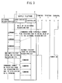
- FIG. 3 shows a sequence view illstrating a communication operation between the external reader/writer 1 and the mobile telephone in the event that a "specific command" is not used.
- the control terminal 14 puts the voltages applied to the terminal V 19 and the terminal P 20 to low levels and the communication state of the non-contact IC 2 is put to the "first communication state".
- Transmission and receipt of various types of information can then take place until the distance between the non-contact IC 2 and the external reader/writer 1 becomes greater than a fixed distance (until the mobile telephone becomes far away from the external reader/writer 1).
- the control unit 14 of the non-contact IC 2 constantly monitors the level of electromagnetic waves from the external reader/writer 1. In the event that the level of electromagnetic waves from the external reader/writer 1 becomes less than a prescribed level, it is recognized that the distance between the non-contact IC 2 and the external reader/writer 1 has become greater than a fixed distance. The control unit 14 then puts the voltages applied to the terminal V 19 and terminal P 20 to high levels and the communication state of the non-contact IC 2 is put to the "second communication state".
- the application manager controller 3 When the non-contact IC 2 enters the "second communication state", electrical power is supplied from the application manager controller 3 to the non-contact IC 2, and communication with the application manager controller 3 is possible.
- the application manager controller 3 When the non-contact IC 2 enters the "second communication state”, the application manager controller 3 carries out communication with the non-contact IC 2, and information taken in by the non-contact IC 2 from the external reader/writer 1 in the first communication state is taken in. The application manager controller 3 then operates based on the information taken-in from the non-contact IC 2.
- buttons etc. provided at the mobile telephone and transmit the operation content to the mobile telephone, or to have prescribed operations carried out automatically by the mobile telephone.
- a "specific command" is sent from the external reader/writer 1 to the non-contact IC 2 during communication between the non-contact IC 2 of the mobile telephone and the external reader/writer 1.
- the communication state of the non-contact IC 2 is changed from the first communication state to the second communication state, and communication between the application manager controller 3 and the non-contact IC 2 is permitted.
- This provides flexibility of communication between the external reader/writer 1, the non-contact IC 2 and the internal application manager controller 3 and ensures that applications designated using a push from the external reader/writer 1 are activated and executed smoothly at the mobile terminal apparatus.
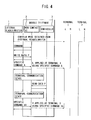
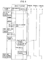
- FIG. 4 shows a sequence view illustrating a communication operation between the external reader/writer 1 and the mobile telephone in the event that a "specific command" is used.
- the voltage applied to the terminal P 20 of the non-contact IC 2 is put to a low level by the control unit 14 as described above, and the non-contact IC 2 carries out communication with the external reader/writer 1 in the first communication state.
- the external reader/writer 1 sends execution application information (data P) designating an application to be started up at the mobile telephone to the non-contact IC 2 and sends a "specific command A" to the non-contact IC 2.
- the control unit 14 of the non-contact IC 2 then performs control to store the execution application information sent from the external reader/writer 1 in volatile memory 13. Further, at the timing of receiving the "specific command A" from the external reader/writer 1, the control unit 14 of the non-contact IC 2 performs control to change the voltage applied to the terminal I 18 from a high-level to a low level, and changes the communication state of the non-contact IC 2 from the first communication state to the second communication state.
- terminal I 18, terminal V 19 and terminal P 20 of the non-contact IC 2 are respectively connected to the application manager controller 3. More specifically, the terminal I 18 of the non-contact IC 2 is connected to an interrupt terminal of the application manager controller 3.
- the application manager controller 3 starts communication with the non-contact IC 2, and makes a transmission request for the execution application information (data P) stored in the volatile memory 13 of the non-contact IC 2.
- control unit 14 of the non-contact IC 2 Upon receiving this transmission request, the control unit 14 of the non-contact IC 2 sends execution application information stored in the volatile memory 13 to the application manager controller 3.
- the control unit 14 of the non-contact IC 2 applies a high-level voltage to the terminal I 18 so as to end communication between the non-contact IC 2 and the application manager controller 3.
- control unit 14 of the non-contact IC 2 to detect that the level of electromagnetic radiation from the external reader/writer 1 has dropped below a prescribed level and apply a high-level voltage to the terminal I 18 at this timing so as to end communication between the non-contact IC 2 and the application manager controller 3. In this way, the step of transmitting and receiving the "specific command IA" can be omitted.
- the application manager controller 3 performs control so as to read an application program corresponding to the execution application information from the application memory 4 and execute the application corresponding to the read-out application program.
- the mobile telephone of the first embodiment transmits a specific command A together with execution application information for designating a prescribed application from the external reader/writer 1 during communication between the external reader/writer 1 and the non-contact IC 2.
- the non-contact IC 2 makes a transmission to the second communication state enabling communication with the application manager controller 3.
- the application manager controller 3 then captures and executes information specifying the application at the timing of the transition.
- the mobile telephone of this embodiment is therefore capable of taking the approach of the mobile telephone to the external reader/writer 1 as a single user interface capable of starting up an application corresponding to the external reader/writer 1 without any user operations.
- the number of users incapable of starting up a desired application also increases.
- this mobile telephone it is possible to obtain desired information at a prescribed timing with a simple operation of bringing the mobile telephone close to the external reader/writer 1.
- non-contact ICs are mainly utilized as cards for automatic ticketing etc. and it is difficult for a display section to be provided on a card as the situation stands.
- a display section to be provided on a card as the situation stands.
- the non-contact IC 2 by providing the non-contact IC 2 within the mobile telephone, information taken in via the non-contact IC 2 can be displayed on a display unit etc. in real time and the usefulness of the non-contact IC 2 can be improved substantially.
- points services where points corresponding to an amount of money for purchased goods are stored on a card (contact or non-contact IC card) and are exchangeable for a product corresponding to the accumulated points afterwards are well known, but dedicated reading equipment is required to confirm the points accumulated on the card and the number of points cannot be confirmed in a straightforward manner by the user.
- a card contact or non-contact IC card
- dedicated reading equipment is required to confirm the points accumulated on the card and the number of points cannot be confirmed in a straightforward manner by the user.
- the mobile telephone of this embodiment if the points are written to a non-contact IC 2 provided within the mobile telephone, it is possible for the user to confirm the points accumulated in a straightforward manner.
- control is exerted so as to store execution application information etc. sent from the external reader/writer 1 to the non-contact IC 2 in the volatile memory 13.
- the non-contact IC 2 it is not possible for the non-contact IC 2 to receive a supply of electrical power from the external reader/writer 1 in the event that the mobile telephone is taken away from the external reader/writer 1 during communication between the external reader/writer 1 and the non-contact IC 2 which gives rise to the inconvenience that the execution application information stored in the volatile memory 13 is volatile.
- the mobile telephone of the second embodiment is therefore provided with non-volatile memory 21 (flash memory) shown by the block of a dotted-line in FIG. 2 for the non-contact IC 2, and the execution application information is stored in this non-volatile memory 21.
- non-volatile memory 21 flash memory
- the "specific command A" is sent to the non-contact IC 2 from the external reader/writer 1 so that the non-contact IC 2 is able to communicate with the application manager controller 3 at the timing where the non-contact IC 2 receives this "specific command A".
- the application manager controller 3 takes in the execution application information stored in the non-volatile memory 21 and after this information is taken in, sends clear information to the non-contact IC 2.
- the control unit 14 of the non-contact IC 2 Upon receiving the clear information from the application manager controller 3, the control unit 14 of the non-contact IC 2 recognizes that taking in of the execution application information by the application manager controller 3 is complete, and deletes the execution application information stored in the non-volatile memory 21.
- execution application information sent from the external reader/writer 1 is taken in by the application manager controller 3 from the non-contact IC 2 taking the "specific command A" sent from the external reader/writer 1 to the non-contact IC 2 as a trigger.
- the execution application information sent from the external reader/writer 1 is taken in by the application manager controller 3 from the non-contact IC 2 taking the mobile telephone being taken away from the external reader/writer 1 as a trigger.
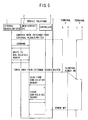
- the control unit 14 changes the voltage applied to the terminal V 19 and the voltage applied to the terminal P 20 from high levels to low levels.
- the communication state of the non-contact IC 2 is then put to the first communication state.
- control unit 14 of the non-contact IC 2 then performs control to write the execution application information sent from the external reader/writer 1 to the non-volatile memory 21 (or the volatile memory 13).
- the control unit 14 changes the voltage applied to the terminal V 19 and the voltage applied to the terminal P 20 from low levels to high levels, and the communication state of the non-contact IC 2 is put to the second communication state.
- the application manager controller 3 then takes in execution application information stored in the non-volatile memory 21 of the non-contact IC 2 and exerts control so as to execute an application corresponding to the execution application information via the device driver and application manager shown in FIG. 1 .
- the application manager controller 3 sends clear information to the non-contact IC 2.
- the control unit 14 of the non-contact IC 2 exerts control to clear execution application information stored in the non-volatile memory 21, changes the voltage applied to the terminal P 20 from a high level to a low level, and closes the line of communication with the application manager controller 3.
- the voltages applied to terminal V 19 and terminal P 20 of the non-contact IC 2 are controlled and the communication state (first communication state or second communication state) of the non-contact IC 2 is made to make transitions according to whether or not supply of electrical power to the non-contact IC 2 of the mobile telephone from the external reader/writer 1 has started.
- the fourth embodiment is an embodiment for the case where the mobile telephone is used in automatic ticketing.
- a sequence view showing communication between an automatic ticketing machine, and the non-contact IC 2 and application manager controller 3 of a mobile telephone in this case is shown in FIG. 6 .
- information such as ticket information and periodic commuter ticket information etc. that it is possible to write when passing through an automatic ticketing machine normally is written to the non-contact IC 2 of the mobile telephone.
- FIG. 6 first, the user brings the mobile telephone close to the external reader/writer 1 of the automatic ticketing machine. As a result, supply of electrical power from the external reader/writer 1 to the non-contact IC 2 of the mobile telephone commences, and the control unit 14 of the non-contact IC 2 changes the voltages applied to the terminal V 19 and the terminal P 20 from high levels to low levels. A transition is then made to the first communication state where communication is carried out with the external reader/writer 1.
- the external reader/writer 1 takes in periodic commuter ticket information and ticket information etc. stored at the non-contact IC 2 and transfers this to a control unit of the automatic ticketing machine.
- the control unit of the automatic ticketing machine checks whether or not a period of validity etc. has ran out based on the transmitted commuter information etc. and, providing the period of validity has not elapsed, opens the gate and allows the user to pass. The operation up to this point is the same as the operation of current automatic ticketing systems.
- the external reader/writer 1 carries out communication with the non-contact IC 2 and determines whether or not the non-contact IC 2 is a specific IC (whether or not the non-contact IC is capable of transmitting the specific command A).
- the non-contact IC 2 currently in communication is a non-contact IC capable of transmitting a specific command A
- the execution application information (data P) and specific command A are transmitted.
- the non-contact IC 2 of the mobile telephone Upon receiving this specific command A, the non-contact IC 2 of the mobile telephone changes the voltage applied to the terminal I 18 from a high level to a low level. As a result, the communication state of the non-contact IC 2 goes to the second communication state and communication with the application manager controller 3 is possible.
- the voltage applied to the interrupt terminal of the application manager controller 3 is also put to a low level by connecting terminal I 18 of the non-contact IC 2 to the interrupt terminal of the application manager controller 3 and putting the voltage applied to the terminal I 18 of the non-contact IC 2 to a low level.
- the application manager controller 3 When it is detected that the voltage applied to the interrupt terminal has fallen to a low level, the application manager controller 3 recognizes this as an application activation instruction from outside. The application manager controller 3 then carries out communication with the non-contact IC 2 and takes in execution application information sent from the external reader/writer 1 to the non-contact IC 2. Execution of the application corresponding to the execution application information is then controlled via the device driver and application manager shown in FIG. 1 . As a result, for example, a balance display application or a deposit application etc. can be made to be automatically started up and executed (action within a terminal) while a user is passing through an automatic ticketing machine.
- the mobile telephone is taken away from the external reader/writer 1 as a result of the user passing through the automatic ticketing machine and the supply of electrical power from the external reader/writer 1 to the non-contact IC 2 is stopped.
- the non-contact IC 2 puts the voltages applied to terminal I 18, terminal V 19 and terminal P 20 to high levels and the communication line with the external reader/writer 1 of the automatic ticketing machine is closed.
- the mobile telephone of the fourth embodiment it is possible to smoothly activate and execute applications designated in push form as described above by the external reader/writer 1 at the mobile terminal apparatus. It is therefore possible for the mobile telephone to confirm that an automatic ticketing machine has been passed through while passing through an automatic ticketing machine using a mobile telephone. In the event that an application is started up and the balance is low, it is possible for deposit processing to be carried out for the non-contact IC 2 at the same time as passing through the automatic ticketing machine. Namely, it is possible for a process for activating an application for deposit processing to be started up and be carried out at the same time as passing through the automatic ticketing machine using the mobile telephone to be achieved with a single process.
- the automatic ticketing machine determines whether a user is getting on or getting off when the mobile telephone comes close to the automatic ticketing machine. As a result, information such at the next train to depart etc. can be given to a user that is getting on in the form of a push to the user of the mobile telephone in real time. Further, as a result of the user inputting their destination into their mobile telephone in advance, it is possible to push information such as a route that gives the shortest time and cheapest fare for the user to arrive at their destination to the mobile telephone of the user in real time.
- communication is carried out between the external reader/writer 1 of the automatic ticketing machine and the non-contact IC 2 of the mobile telephone while a user that is getting on passes through the automatic ticketing machine.
- An application to go into silent vibration mode or turn the power off is activated, and the mobile telephone of the user can therefore be automatically put into silent vibration mode or can be turned off.
- communication may also be carried out between the external reader/writer 1 of the automatic ticketing machine and the non-contact IC 2 of the mobile telephone while a user that is getting off passes through the automatic ticketing machine. It is then possible to deactivate the settings for silent vibration mode or for turning the power off that were set at the time of getting on.
- communication may also be carried out between the external reader/writer 1 of the automatic ticketing machine and the non-contact IC 2 of the mobile telephone while a user that is getting off passes through the automatic ticketing machine. It is then possible for advertising for the surrounding area or street information to be pushed in real-time.
- the mobile telephone is by no means limited to being used with automatic ticketing systems, and may also be utilized in payments at register apparatuses of department stores or supermarket stores and payments when getting on or getting on buses.
- a balance display application may be activated and the balance displayed, or a deposit processing application may be activated so that a deposit may be made automatically.
- the mobile telephone is capable of automatically starting up mobile telephone applications in the form of a push from the external reader/writer 1.
- Applications are therefore possible in various services such as when, with a points service, a product is purchased or a service is utilized, a roulette application is automatically activated at the mobile telephone so that when a prescribed item appears a larger number of points than usual are assigned.
Landscapes
- Engineering & Computer Science (AREA)
- Physics & Mathematics (AREA)
- General Physics & Mathematics (AREA)
- Business, Economics & Management (AREA)
- Theoretical Computer Science (AREA)
- Computer Networks & Wireless Communication (AREA)
- Microelectronics & Electronic Packaging (AREA)
- Accounting & Taxation (AREA)
- Strategic Management (AREA)
- General Business, Economics & Management (AREA)
- Computer Vision & Pattern Recognition (AREA)
- Artificial Intelligence (AREA)
- Signal Processing (AREA)
- Telephone Function (AREA)
- Stored Programmes (AREA)
- Near-Field Transmission Systems (AREA)
- Mobile Radio Communication Systems (AREA)
Claims (5)
- Appareil terminal mobile, comprenant :des moyens de contrôle internes (3) pour le contrôle et l'exécution d'applications ; etdes moyens de communication sans contact (2) qui communiquent dans un premier état de communication avec un appareil de communication externe (1) sur de courtes distances et dans un second état de communication avec lesdits moyens de contrôle internes (3),caractérisé en ce que,lesdits moyens de communication sans contact (2) comprennent- des moyens de réception (11, 12) adaptés pour recevoir au moins des informations d'interruption et des informations concernant l'exécution d'une application en provenance dudit appareil de communication externe (1) dans le premier état de communication, et- des moyens de changement d'état de communication (14) adaptés pour changer ledit premier état de communication en ledit second état de communication lorsque lesdites informations d'interruption sont reçues par lesdits moyens de réception (11, 12), et- des moyens de notification (18, 19, 20) adaptés pour notifier auxdits moyens de contrôle internes (3) quand l'état de communication des moyens de communication sans contact (2) est changé, etlorsque lesdits moyens de contrôle internes (3) se voient notifier le changement d'état de communication, les moyens de contrôle internes (3) prennent lesdites informations d'exécution d'application et les applications sont exécutées correspondant auxdites informations d'exécution d'application par les moyens de contrôle internes (3).
- Appareil terminal mobile selon l'une quelconque des revendications précédentes,
caractérisé en ce que,
lesdits moyens de communication sans contact (2) comprennent en outre des moyens de mémoire non volatile (13) pour stocker des informations d'exécution d'application transmises de l'appareil de communication externe (1) aux moyens de communication sans contact (2), où lesdits moyens de contrôle internes (3) prennent lesdites informations d'exécution d'application lorsque ladite notification est donnée selon laquelle l'état de communication est changé au second état, et les informations d'exécution d'application sont effacées après ladite prise. - Appareil terminal mobile selon l'une quelconque des revendications précédentes,
caractérisé en ce que,
lesdits moyens de communication sans contact (2) comprennent des moyens de détection pour détecter si une communication avec ledit appareil de communication externe (1) est commencée lorsque le niveau d'ondes électromagnétiques depuis ledit appareil de communication externe (1) devient supérieur à un niveau prescrit, et détecter qu'une communication avec ledit appareil de communication externe (1) est terminée lorsque le niveau d'ondes électromagnétiques depuis ledit appareil de communication externe (1) devient inférieur à un niveau prescrit. - Appareil terminal mobile selon l'une quelconque des revendications précédentes,
caractérisé en ce que,
lesdits moyens de communication sans contact (2) comprennent en outre des moyens de mémoire non volatile (13) pour stocker des informations d'exécution d'application transmises de l'appareil de communication externe (1) aux moyens de communication sans contact (2), où lesdits moyens de contrôle internes (3) prennent lesdites informations d'exécution d'application lorsque lesdits moyens de détection de communication détectent qu'une communication avec ledit appareil externe (1) est terminée et lesdits moyens de changement d'état de communication (14) changent l'état de communication au second état, et les informations d'exécution d'application sont effacées après ladite prise. - Appareil terminal mobile selon l'une quelconque des revendications précédentes,
caractérisé en ce que,
lesdits moyens de réception comprennent une unité radiofréquence (12) pour recevoir au moins des informations d'interruption et des informations concernant l'exécution d'une application en provenance dudit appareil de communication externe (1) dans le premier état de communication.
Applications Claiming Priority (2)
| Application Number | Priority Date | Filing Date | Title |
|---|---|---|---|
| JP2003342582A JP4416077B2 (ja) | 2003-09-30 | 2003-09-30 | 携帯端末装置 |
| JP2003342582 | 2003-09-30 |
Publications (2)
| Publication Number | Publication Date |
|---|---|
| EP1521201A1 EP1521201A1 (fr) | 2005-04-06 |
| EP1521201B1 true EP1521201B1 (fr) | 2010-01-20 |
Family
ID=34309098
Family Applications (1)
| Application Number | Title | Priority Date | Filing Date |
|---|---|---|---|
| EP04023341A Expired - Fee Related EP1521201B1 (fr) | 2003-09-30 | 2004-09-30 | Appareil terminal mobile |
Country Status (8)
| Country | Link |
|---|---|
| US (2) | US7184706B2 (fr) |
| EP (1) | EP1521201B1 (fr) |
| JP (1) | JP4416077B2 (fr) |
| KR (1) | KR101036525B1 (fr) |
| CN (1) | CN1316420C (fr) |
| DE (1) | DE602004025184D1 (fr) |
| HK (1) | HK1071460A1 (fr) |
| SG (1) | SG110159A1 (fr) |
Families Citing this family (44)
| Publication number | Priority date | Publication date | Assignee | Title |
|---|---|---|---|---|
| US7775432B2 (en) | 2003-10-16 | 2010-08-17 | Nokia Corporation | Terminal, method and computer program product for interacting with a signaling tag |
| JP4337619B2 (ja) * | 2004-04-28 | 2009-09-30 | 株式会社デンソーウェーブ | サポートシステム |
| JP2006134210A (ja) * | 2004-11-09 | 2006-05-25 | Ntt Docomo Inc | 移動体端末装置及びそれを用いたデータ取得方法 |
| JP4169158B2 (ja) * | 2004-12-24 | 2008-10-22 | インターナショナル・ビジネス・マシーンズ・コーポレーション | 無線icチップおよびこれを用いた位置認識システム並びにセキュリティシステム |
| JP2006190210A (ja) * | 2005-01-07 | 2006-07-20 | Fuji Xerox Co Ltd | 非接触ic |
| US7726566B2 (en) * | 2005-04-15 | 2010-06-01 | Research In Motion Limited | Controlling connectivity of a wireless smart card reader |
| US9398137B2 (en) | 2005-04-19 | 2016-07-19 | Nokia Technologies Oy | Method, device and system for controlling application launching in a mobile terminal device |
| JP5430050B2 (ja) | 2005-06-24 | 2014-02-26 | フェリカネットワークス株式会社 | データ通信システム、icカード機能を実行するデバイス及びその制御方法、並びに情報処理端末 |
| JP4857270B2 (ja) | 2005-06-29 | 2012-01-18 | パナソニック株式会社 | 非接触icカードを備えた携帯端末装置 |
| JP4917768B2 (ja) * | 2005-07-06 | 2012-04-18 | 東日本旅客鉄道株式会社 | 自動改札機による情報提供システム |
| JP4812371B2 (ja) * | 2005-08-29 | 2011-11-09 | 東海理研株式会社 | 画像表示制御システム、認証システム及びアプリケーション管理装置 |
| JP4777725B2 (ja) * | 2005-08-31 | 2011-09-21 | フェリカネットワークス株式会社 | 携帯端末装置,サーバ装置,アプリケーション提供方法およびコンピュータプログラム |
| JP2007074102A (ja) * | 2005-09-05 | 2007-03-22 | Ntt Docomo Inc | 移動体端末装置及び受信感度報知方法 |
| US11201500B2 (en) | 2006-01-31 | 2021-12-14 | Mojo Mobility, Inc. | Efficiencies and flexibilities in inductive (wireless) charging |
| US8169185B2 (en) | 2006-01-31 | 2012-05-01 | Mojo Mobility, Inc. | System and method for inductive charging of portable devices |
| US7952322B2 (en) | 2006-01-31 | 2011-05-31 | Mojo Mobility, Inc. | Inductive power source and charging system |
| WO2007118093A2 (fr) * | 2006-04-03 | 2007-10-18 | Sennari, Inc. | Système et procédé de billetterie virtuelle par téléphone mobile |
| WO2007121607A1 (fr) * | 2006-04-20 | 2007-11-01 | Utstarcom Telecom Co., Ltd. | Dispositif portable à fonction carte intelligente sans contact |
| US11329511B2 (en) | 2006-06-01 | 2022-05-10 | Mojo Mobility Inc. | Power source, charging system, and inductive receiver for mobile devices |
| US7948208B2 (en) | 2006-06-01 | 2011-05-24 | Mojo Mobility, Inc. | Power source, charging system, and inductive receiver for mobile devices |
| US10311427B2 (en) * | 2006-12-29 | 2019-06-04 | Google Technology Holdings LLC | Method and system for monitoring secure application execution events during contactless RFID/NFC communication |
| JP5202992B2 (ja) * | 2008-02-29 | 2013-06-05 | Jr東日本メカトロニクス株式会社 | 通信端末装置、プログラム及び利用情報配信システム |
| JP5197112B2 (ja) | 2008-04-04 | 2013-05-15 | キヤノン株式会社 | 通信装置、その制御方法及びプログラム |
| US20110050164A1 (en) | 2008-05-07 | 2011-03-03 | Afshin Partovi | System and methods for inductive charging, and improvements and uses thereof |
| JP5413637B2 (ja) * | 2008-09-12 | 2014-02-12 | ソニー株式会社 | Icチップ、情報処理装置、ソフトウェアモジュール制御方法、情報処理システムおよび方法、並びにプログラム |
| JP5288618B2 (ja) * | 2009-05-21 | 2013-09-11 | パナソニック株式会社 | 携帯機器 |
| CN102110233A (zh) * | 2009-12-24 | 2011-06-29 | 上海华虹集成电路有限责任公司 | 非接触ic卡读写器的实现方法 |
| WO2011156768A2 (fr) | 2010-06-11 | 2011-12-15 | Mojo Mobility, Inc. | Système de transfert d'énergie sans fil prenant en charge l'interopérabilité et aimants multipolaires à utiliser avec ce système |
| US9178369B2 (en) | 2011-01-18 | 2015-11-03 | Mojo Mobility, Inc. | Systems and methods for providing positioning freedom, and support of different voltages, protocols, and power levels in a wireless power system |
| US11342777B2 (en) | 2011-01-18 | 2022-05-24 | Mojo Mobility, Inc. | Powering and/or charging with more than one protocol |
| US9496732B2 (en) | 2011-01-18 | 2016-11-15 | Mojo Mobility, Inc. | Systems and methods for wireless power transfer |
| US10115520B2 (en) | 2011-01-18 | 2018-10-30 | Mojo Mobility, Inc. | Systems and method for wireless power transfer |
| JP5180331B2 (ja) * | 2011-02-01 | 2013-04-10 | フェリカネットワークス株式会社 | 通信端末、サーバ装置、通信方法およびプログラム |
| KR20130062104A (ko) * | 2011-12-02 | 2013-06-12 | 삼성전자주식회사 | 복수의 가로등들을 제어하는 방법 및 가로등 제어시스템 |
| JP2013182369A (ja) * | 2012-03-01 | 2013-09-12 | Dainippon Printing Co Ltd | リーダライタ、アプリケーション起動方法、及びアプリケーション起動プログラム |
| JP5974546B2 (ja) * | 2012-03-01 | 2016-08-23 | 大日本印刷株式会社 | リーダライタ、アプリケーション起動確認方法、及びアプリケーション起動確認プログラム |
| US20130271069A1 (en) | 2012-03-21 | 2013-10-17 | Mojo Mobility, Inc. | Systems and methods for wireless power transfer |
| US9722447B2 (en) | 2012-03-21 | 2017-08-01 | Mojo Mobility, Inc. | System and method for charging or powering devices, such as robots, electric vehicles, or other mobile devices or equipment |
| CN102801853B (zh) * | 2012-06-27 | 2017-02-15 | 宇龙计算机通信科技(深圳)有限公司 | 移动终端和自动触发任务执行方法 |
| JP6040617B2 (ja) * | 2012-07-30 | 2016-12-07 | ソニー株式会社 | 通信装置、情報処理方法、およびプログラム |
| US9837846B2 (en) | 2013-04-12 | 2017-12-05 | Mojo Mobility, Inc. | System and method for powering or charging receivers or devices having small surface areas or volumes |
| JP6214470B2 (ja) * | 2014-05-26 | 2017-10-18 | 東芝テック株式会社 | 商品販売データ処理装置、据置型装置、情報端末及びそのプログラム |
| DE112019006454T5 (de) | 2018-12-28 | 2021-11-04 | Sony Group Corporation | Kommunikationsvorrichtung und Kommunikationsverfahren |
| US11444485B2 (en) | 2019-02-05 | 2022-09-13 | Mojo Mobility, Inc. | Inductive charging system with charging electronics physically separated from charging coil |
Family Cites Families (13)
| Publication number | Priority date | Publication date | Assignee | Title |
|---|---|---|---|---|
| JP3068745B2 (ja) * | 1994-05-27 | 2000-07-24 | ローム株式会社 | 高周波タグおよびこれを利用した情報交換システム |
| US5465401A (en) | 1992-12-15 | 1995-11-07 | Texas Instruments Incorporated | Communication system and methods for enhanced information transfer |
| WO1999022538A1 (fr) | 1997-10-28 | 1999-05-06 | Motorola Inc. | Module de communication par radio frequence (rf) et son procede d'utilisation |
| SE514433C2 (sv) | 1998-05-08 | 2001-02-26 | Ericsson Telefon Ab L M | Förfarande och anordning i ett trådlöst kommunikationssystem |
| JP2000259790A (ja) * | 1999-03-09 | 2000-09-22 | Matsushita Electric Ind Co Ltd | 非接触式読み取り書き込み機 |
| EP1098271A1 (fr) | 1999-11-03 | 2001-05-09 | Kim, Seon-seob | Téléphone portable muni d'une carte à puce sans contact |
| EP1204903A4 (fr) * | 2000-05-30 | 2005-05-04 | Seiko Epson Corp | Dispositif electronique portatif |
| FR2810764B1 (fr) | 2000-06-22 | 2003-01-24 | Bouygues Telecom Sa | Ensemble permettant de lire automatiquement une information et systeme de controle ou de suivi a distance comportant au moins un tel ensemble |
| JP2002351623A (ja) * | 2001-05-23 | 2002-12-06 | Fujitsu Ltd | 携帯電話機 |
| JP2003044801A (ja) * | 2001-07-27 | 2003-02-14 | Dainippon Printing Co Ltd | 複数の情報伝達手段を備えた可搬情報処理装置 |
| US7344074B2 (en) * | 2002-04-08 | 2008-03-18 | Nokia Corporation | Mobile terminal featuring smart card interrupt |
| US7215978B2 (en) * | 2002-10-09 | 2007-05-08 | Nec Corporation | Mobile terminal apparatus, mobile terminal settings changing system, method used therefor, and program thereof |
| JP3993108B2 (ja) * | 2003-01-17 | 2007-10-17 | ソニー・エリクソン・モバイルコミュニケーションズ株式会社 | 無線通信方法及び無線通信端末 |
-
2003
- 2003-09-30 JP JP2003342582A patent/JP4416077B2/ja not_active Expired - Fee Related
-
2004
- 2004-09-24 SG SG200405361A patent/SG110159A1/en unknown
- 2004-09-24 US US10/948,148 patent/US7184706B2/en active Active
- 2004-09-29 CN CNB2004100832610A patent/CN1316420C/zh not_active Expired - Fee Related
- 2004-09-30 KR KR1020040077905A patent/KR101036525B1/ko active IP Right Grant
- 2004-09-30 EP EP04023341A patent/EP1521201B1/fr not_active Expired - Fee Related
- 2004-09-30 DE DE602004025184T patent/DE602004025184D1/de active Active
-
2005
- 2005-05-13 HK HK05104016A patent/HK1071460A1/xx not_active IP Right Cessation
-
2006
- 2006-11-10 US US11/558,483 patent/US7526311B2/en not_active Expired - Fee Related
Also Published As
| Publication number | Publication date |
|---|---|
| JP2005108044A (ja) | 2005-04-21 |
| US7526311B2 (en) | 2009-04-28 |
| KR101036525B1 (ko) | 2011-05-24 |
| EP1521201A1 (fr) | 2005-04-06 |
| HK1071460A1 (en) | 2005-07-15 |
| CN1604130A (zh) | 2005-04-06 |
| JP4416077B2 (ja) | 2010-02-17 |
| US7184706B2 (en) | 2007-02-27 |
| DE602004025184D1 (de) | 2010-03-11 |
| US20050108317A1 (en) | 2005-05-19 |
| SG110159A1 (en) | 2005-04-28 |
| US20070087786A1 (en) | 2007-04-19 |
| CN1316420C (zh) | 2007-05-16 |
| KR20050032002A (ko) | 2005-04-06 |
Similar Documents
| Publication | Publication Date | Title |
|---|---|---|
| EP1521201B1 (fr) | Appareil terminal mobile | |
| US8960531B2 (en) | Data communications system, information processing terminal, IC card, reader/writer, and program | |
| KR101316679B1 (ko) | 데이터 통신 시스템, ic 카드 기능을 실행하는 디바이스및 그 제어 방법, 및 정보 처리 단말기 | |
| TWI459739B (zh) | 用於在近場通訊模式下獲取並利用能量之設備 | |
| JP2003141477A (ja) | Icチップ及び情報処理端末 | |
| CN102047748A (zh) | 用于使用多个发现管理器在电子装置中进行自动应用程序选择的方法和设备 | |
| JP2011526011A (ja) | Nfcシステムでのワイヤレス移動体通信装置のアプリケーション選択方法および対応するワイヤレス移動体通信装置 | |
| JP2009205234A (ja) | 電子決済システム、およびその方法、プログラム、媒体 | |
| JP2006260196A (ja) | 電子マネー決済システム、そのシステムに用いる通信携帯端末、および、そのシステムに用いる非接触icカード | |
| JPWO2005027029A1 (ja) | 情報記憶装置と情報処理装置 | |
| CN104156741A (zh) | 包括智能卡模块和近场通信装置的方法和移动终端设备 | |
| JP4390106B2 (ja) | 通信装置 | |
| KR100678724B1 (ko) | 오프카드모듈 인터페이스를 구비한 무선단말기 및 이무선단말기를 이용한 모바일서버와 ic 카드간인터페이스 방법 | |
| KR20160147694A (ko) | 마이크로 sd카드를 이용한 nfc 결제 방법 | |
| JP5518109B2 (ja) | 通信装置及び通信方法、並びにプログラム | |
| CN115204343A (zh) | 具有标准适应计数器递增的rfid标签ic以及rfid通信系统 | |
| CN101383010A (zh) | 一种带有智能存储卡插槽的卡片及其应用 | |
| KR20060112367A (ko) | 엠피쓰리플레이어를 이용한 전자지불수단 전환시스템 및 그방법 | |
| JP2003122281A (ja) | チケット付き広告システム |
Legal Events
| Date | Code | Title | Description |
|---|---|---|---|
| PUAI | Public reference made under article 153(3) epc to a published international application that has entered the european phase |
Free format text: ORIGINAL CODE: 0009012 |
|
| AK | Designated contracting states |
Kind code of ref document: A1 Designated state(s): AT BE BG CH CY CZ DE DK EE ES FI FR GB GR HU IE IT LI LU MC NL PL PT RO SE SI SK TR |
|
| AX | Request for extension of the european patent |
Extension state: AL HR LT LV MK |
|
| 17P | Request for examination filed |
Effective date: 20050826 |
|
| AKX | Designation fees paid |
Designated state(s): DE FR GB |
|
| 17Q | First examination report despatched |
Effective date: 20070712 |
|
| GRAJ | Information related to disapproval of communication of intention to grant by the applicant or resumption of examination proceedings by the epo deleted |
Free format text: ORIGINAL CODE: EPIDOSDIGR1 |
|
| GRAP | Despatch of communication of intention to grant a patent |
Free format text: ORIGINAL CODE: EPIDOSNIGR1 |
|
| GRAP | Despatch of communication of intention to grant a patent |
Free format text: ORIGINAL CODE: EPIDOSNIGR1 |
|
| RIC1 | Information provided on ipc code assigned before grant |
Ipc: H04W 88/02 20090101ALI20090818BHEP Ipc: H04M 1/725 20060101ALI20090818BHEP Ipc: G06K 19/07 20060101ALI20090818BHEP Ipc: G06K 7/00 20060101AFI20090818BHEP |
|
| GRAS | Grant fee paid |
Free format text: ORIGINAL CODE: EPIDOSNIGR3 |
|
| GRAA | (expected) grant |
Free format text: ORIGINAL CODE: 0009210 |
|
| AK | Designated contracting states |
Kind code of ref document: B1 Designated state(s): DE FR GB |
|
| REG | Reference to a national code |
Ref country code: GB Ref legal event code: FG4D |
|
| REF | Corresponds to: |
Ref document number: 602004025184 Country of ref document: DE Date of ref document: 20100311 Kind code of ref document: P |
|
| PLBE | No opposition filed within time limit |
Free format text: ORIGINAL CODE: 0009261 |
|
| STAA | Information on the status of an ep patent application or granted ep patent |
Free format text: STATUS: NO OPPOSITION FILED WITHIN TIME LIMIT |
|
| 26N | No opposition filed |
Effective date: 20101021 |
|
| REG | Reference to a national code |
Ref country code: FR Ref legal event code: PLFP Year of fee payment: 13 |
|
| REG | Reference to a national code |
Ref country code: FR Ref legal event code: PLFP Year of fee payment: 14 |
|
| REG | Reference to a national code |
Ref country code: FR Ref legal event code: PLFP Year of fee payment: 15 |
|
| PGFP | Annual fee paid to national office [announced via postgrant information from national office to epo] |
Ref country code: DE Payment date: 20190917 Year of fee payment: 16 Ref country code: FR Payment date: 20190829 Year of fee payment: 16 |
|
| PGFP | Annual fee paid to national office [announced via postgrant information from national office to epo] |
Ref country code: GB Payment date: 20190926 Year of fee payment: 16 |
|
| REG | Reference to a national code |
Ref country code: DE Ref legal event code: R119 Ref document number: 602004025184 Country of ref document: DE |
|
| GBPC | Gb: european patent ceased through non-payment of renewal fee |
Effective date: 20200930 |
|
| PG25 | Lapsed in a contracting state [announced via postgrant information from national office to epo] |
Ref country code: DE Free format text: LAPSE BECAUSE OF NON-PAYMENT OF DUE FEES Effective date: 20210401 Ref country code: FR Free format text: LAPSE BECAUSE OF NON-PAYMENT OF DUE FEES Effective date: 20200930 |
|
| PG25 | Lapsed in a contracting state [announced via postgrant information from national office to epo] |
Ref country code: GB Free format text: LAPSE BECAUSE OF NON-PAYMENT OF DUE FEES Effective date: 20200930 |