EP1520818B1 - Vorrichtung und Verfahren zum Verstellen der Phase von Falzwalzen in einer Ineinanderfaltmaschine - Google Patents
Vorrichtung und Verfahren zum Verstellen der Phase von Falzwalzen in einer Ineinanderfaltmaschine Download PDFInfo
- Publication number
- EP1520818B1 EP1520818B1 EP04256071A EP04256071A EP1520818B1 EP 1520818 B1 EP1520818 B1 EP 1520818B1 EP 04256071 A EP04256071 A EP 04256071A EP 04256071 A EP04256071 A EP 04256071A EP 1520818 B1 EP1520818 B1 EP 1520818B1
- Authority
- EP
- European Patent Office
- Prior art keywords
- roll
- shaft
- gear
- rolls
- folding
- Prior art date
- Legal status (The legal status is an assumption and is not a legal conclusion. Google has not performed a legal analysis and makes no representation as to the accuracy of the status listed.)
- Expired - Lifetime
Links
Images


Classifications
-
- B—PERFORMING OPERATIONS; TRANSPORTING
- B65—CONVEYING; PACKING; STORING; HANDLING THIN OR FILAMENTARY MATERIAL
- B65H—HANDLING THIN OR FILAMENTARY MATERIAL, e.g. SHEETS, WEBS, CABLES
- B65H45/00—Folding thin material
- B65H45/12—Folding articles or webs with application of pressure to define or form crease lines
- B65H45/24—Interfolding sheets, e.g. cigarette or toilet papers
-
- B—PERFORMING OPERATIONS; TRANSPORTING
- B65—CONVEYING; PACKING; STORING; HANDLING THIN OR FILAMENTARY MATERIAL
- B65H—HANDLING THIN OR FILAMENTARY MATERIAL, e.g. SHEETS, WEBS, CABLES
- B65H29/00—Delivering or advancing articles from machines; Advancing articles to or into piles
- B65H29/66—Advancing articles in overlapping streams
- B65H29/6609—Advancing articles in overlapping streams forming an overlapping stream
- B65H29/6618—Advancing articles in overlapping streams forming an overlapping stream upon transfer from a first conveyor to a second conveyor advancing at slower speed
-
- B—PERFORMING OPERATIONS; TRANSPORTING
- B65—CONVEYING; PACKING; STORING; HANDLING THIN OR FILAMENTARY MATERIAL
- B65H—HANDLING THIN OR FILAMENTARY MATERIAL, e.g. SHEETS, WEBS, CABLES
- B65H2220/00—Function indicators
- B65H2220/09—Function indicators indicating that several of an entity are present
-
- B—PERFORMING OPERATIONS; TRANSPORTING
- B65—CONVEYING; PACKING; STORING; HANDLING THIN OR FILAMENTARY MATERIAL
- B65H—HANDLING THIN OR FILAMENTARY MATERIAL, e.g. SHEETS, WEBS, CABLES
- B65H2403/00—Power transmission; Driving means
- B65H2403/40—Toothed gearings
- B65H2403/45—Toothed gearings helical gearing
-
- B—PERFORMING OPERATIONS; TRANSPORTING
- B65—CONVEYING; PACKING; STORING; HANDLING THIN OR FILAMENTARY MATERIAL
- B65H—HANDLING THIN OR FILAMENTARY MATERIAL, e.g. SHEETS, WEBS, CABLES
- B65H2511/00—Dimensions; Position; Numbers; Identification; Occurrences
- B65H2511/20—Location in space
- B65H2511/21—Angle
- B65H2511/212—Rotary position
-
- B—PERFORMING OPERATIONS; TRANSPORTING
- B65—CONVEYING; PACKING; STORING; HANDLING THIN OR FILAMENTARY MATERIAL
- B65H—HANDLING THIN OR FILAMENTARY MATERIAL, e.g. SHEETS, WEBS, CABLES
- B65H2701/00—Handled material; Storage means
- B65H2701/10—Handled articles or webs
- B65H2701/19—Specific article or web
- B65H2701/1924—Napkins or tissues, e.g. dressings, toweling, serviettes, kitchen paper and compresses
Definitions
- This invention generally relates to an interfolding machine for interfolding sheets of material, and more specifically, to an interfolding machine that includes folding rolls having a timing assembly configured to allow adjustments in the phasing between the folding rolls while the interfolding machine is running.
- Folding of web or sheet material is frequently performed using a pair of folding rolls that have interacting mechanical gripper and tucker assemblies.
- the gripper and tucker assemblies are uniformly spaced around a circumference of each respective folding roll to interact with one another so as to interfold the sheets of material.
- the tucker assemblies on one roll interact with the gripper assemblies of the adjacent roll, and vice versa, to alternately grip and tuck successive sheets of material fed between the rolls.
- the gripper assemblies carry and release the folded sheets of material to create a zigzagged interfolded stack of sheets.
- the folding rolls rotate in a specified timed or phased manner to provide the desired function of folding the sheets at a desired location so as to create the zigzag interfolded stack of sheets, and to ensure that the grippers and tuckers engage the sheet and each other in a desired position.
- the interfolding machine is stopped and an operator rotates one of the folding rolls to adjust its position relative to the other, to provide the desired phasing between the rolls.
- the folding rolls of known interfolding machines are normally gear driven from a drive system that also drives other components of the machine.
- the phasing between the folding rolls controls the location of the fold in the sheet, as well as the position of engagement between the grippers and tuckers of the folding rolls.
- the hub is slotted so the folding rolls can be manually rotated.
- known folding machinery has several drawbacks.
- known folding machinery requires that adjustments be made to the phasing of the gear drives of the folding rolls in order to provide the fold crease in the desired location on the sheet and to adjust the relative positions of the folding rolls. These phasing adjustments require the operator to shutdown the machinery, disassemble the gear drives, and make adjustments on a trial and error basis. These adjustments are costly, cumbersome and time consuming.
- JP-A-01 192669 which is considered to represent the closest prior art, discloses a printing machine having rotating nipping and reduction drums, a gear mechanism, interlinking the drums and being adjustable to regulating the phase between the drums.
- an interfolding machine according to claim 1.
- the present invention further provides a method of adjusting a phasing of an interfolding machine according to claim 7.
- the interfolding machine is configured to interfold sheet material, which generally includes a first folding roll and a second folding roll disposed adjacent the first roll.
- the first and second rolls are configured to provide a fold or crease in the sheet material.
- the upstream roll may be a lap roll, and a phase adjustment assembly or apparatus has a helical drive gear interconnected with the at least one of the folding rolls and the upstream roll, and an input arrangement having at least one helical input gear that is engaged with the helical drive gear.
- the helical input gear is operable to move along an axial direction relative to the longitudinal axes of the folding rolls.
- the helical drive gear is connected to the folding roll such that axial movement of the helical input gear causes an adjustment in the rotational position of the folding roll through the helical drive gear, which thereby adjusts the phasing between the folding rolls and the upstream portion of the machine where lapping and cutting of the sheets occurs, while the interfolding machine is in operation.
- the adjustment in the phasing of the folding rolls causes an adjustment in the relative positions of the grippers and tuckers relative to the upstream portion of the machine that supplies the sheets to the folding rolls, and thereby in the location of the fold or crease in the sheet material created by operation of the grippers and tuckers.
- the phase adjustment assembly includes a first drive gear that is mounted to the first shaft and a second drive gear that is mounted to the second shaft.
- An input arrangement includes a pair of axially movable input gears that are engaged with the first and second drive gears, and an input device configured to cause axial movement of the pair of axially movable input gears. Such axial movement of the input gears alters the axial position of engagement between the input gears and the drive gears, and the helical orientation of the gear teeth causes rotation of the first and second shafts, and thereby the first and second rolls, to adjust the phasing between the first and second rolls while the machine is running.
- the input device includes an adjustment actuator that includes a handwheel, and a shaft coupling the handwheel to the input gears such that adjustment of the adjustment handwheel causes axial movement of the shaft and the input gears.
- the input device further includes a locking device configured to secure the position of the shaft and the input gears in a desired position.
- the shaft includes a threaded adjustment feature that is operable to vary the position of the input gears upon rotation of the shaft.
- the act of adjusting the relative positions of the rolls is carried out via a helical drive gear that rotates with at least one of the rolls, in combination with an axially movable helical input gear that is engaged with the helical drive gear.
- the act of adjusting the relative positions of the rolls is carried out by axially moving the helical input gear, such as by operation of a handwheel, which causes rotational movement of the helical drive gear and thereby rotation of the first roll relative to the second roll to shift the phasing between the first and second rolls.
- an interfolding machine 25 is operable to convert a web of material 30 into a stack of interfolded sheets of material shown at 32.
- Interfolding machine 25 incorporates folding rolls incorporating the folding roll phase adjustment assembly of the present invention, and generally includes a first pull roll 35 and a second pull roll 40 that receive the web of material 30 along a path (illustrated by an arrow 42 in FIG. 2 ) from a supply roll (not shown) into the interfolding machine 20.
- the first and second pull rolls 35 and 40 define a nip through which the web of material 30 passes, and function to unwind the web of material 30 and feed the web of material 30 in a path (illustrated by an arrow 44 in FIG.
- the knife roll 50 cuts the web of material 30 into sheets, each of which has a predetermined length, and the bed roll 45 carries the sheets of material along a path (illustrated by arrow 52 in FIG. 2 ) toward and through a nip defined between bed roll 45 and a retard roll 55, which rotates at a slower speed of rotation than the bed roll 45.
- the retard roll 55 cooperates with a nip roller assembly 60 ( FIG. 2 ) to form an overlap between the consecutive sheets of material.
- the retard roll 55 carries the overlapped sheets of material along a path (illustrated by arrow 68 in FIG. 2 ) to a lap roll 65.
- the lap roll 65 works in combination with a count roll 75 to eliminate the overlap between adjacent sheets of material at a predetermined sheet count, so as to create a separation in the stack 32 of interfolded sheets discharged from the interfolding machine 25.
- the lap roll 65 carries the overlapped sheets of sheet material 30 along a path (illustrated by arrow 78 in FIG. 2 ) toward a nip defined between a first assist roll 80 and an adjacent second assist roll 85.
- the first and second assist rolls 80 and 85 feed the sheets of sheet material 30 between a first folding roll 90 and a second folding roll 95.
- the first and second folding rolls 90 and 95 generally rotate in opposite directions (illustrated by arrows 96 and 98, respectively, in FIG. 2 ) to receive the overlapped sheets of material 30 therebetween.
- the periphery of the first folding roll 90 generally includes a series of the gripper assemblies 100 and a series of tucker assemblies 105 uniformly and alternately spaced to interact with a series of gripper assemblies 100 and tucker assemblies 105 of the adjacent second folding roll 95.
- the series of alternately spaced gripper assemblies 100 and tucker assemblies 105 of the first and second folding rolls 90 and 95 interact to grip, carry, and release the sheet material 30 in a desired manner so as to form the desired interfolded relationship in the sheets of material and to form stack 32 of interfolded sheets.
- the folding rolls 90 and 95 may be driven by a drive system 110 having a drive belt assembly 115 ( FIG. 1 ).
- each of the gripper assemblies 100 is generally located at a distance from the next tucker assembly 105 along the circumference of each of the first and second folding rolls 90 and 95.
- the spacing between gripper assemblies 100 and tucker assemblies 105 determines the longitudinal dimension or length between the folds in the sheet material 30 as measured in a direction of travel (illustrated by arrows 96 and 98) of the first and second folding rolls 90 and 95.
- the stack 32 of interfolded sheets is discharged from between the first and second folding rolls 90 and 95 in a generally vertically-aligned fashion.
- the stack 32 of interfolded sheets may be supplied to a discharge and transfer system (not shown), which guides and conveys the stack 32 from the generally vertically-aligned orientation at the discharge of the interfolding machine 25 to a generally horizontally-aligned movement.
- a discharge and transfer system is described in U.S. Patent No. 6,712,746 entitled “Discharge and Transfer System for Interfolded Sheets," filed May 5, 2000, the disclosure of which is hereby incorporated herein by reference in its entirety.
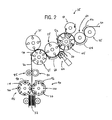
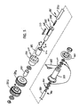
- FIGS. 3 and 4 show a phase adjustment assembly 20 in accordance with the present invention, which is configured to adjust the phase of the folding roll 90 relative to the lap roll 65, which work in concert to create a fold in a downstream sheet of material 30 at the location of the leading edge of an upstream sheet of material 30.
- the phase adjustment assembly 20 generally includes a drive train 118 with a first split helical drive gear 120, a pair of helical input or input gears 125a and 125b, respectively, and a second split helical drive gear 130.
- phase adjustment assembly further includes an input shaft 135, an input bearing 140, a bushing 141, a threaded stud 145, an actuator or adjustment shaft 150, a handwheel housing 155, a handwheel 160, a locking collar 165, and a shaft housing 170.
- the adjustment shaft 150 is configured to be selectively rotated, which results in axial movement of the input shaft 135 through threaded stud 145.
- the pair of helical input gears 125a and 125b are mounted to the input shaft 135 via input bearings 140a and 140b, so that helical input gears 125a and 125b are rotatably supported on bearings 140a and 140b, respectively.
- rotational movement of the adjustment shaft 150 (illustrated by arrow 173) causes axial movement of the helical input gears 125a and 125b.
- the helical input gear 125a engages folding roll split helical drive gear 120
- the helical input gear 125b engages lap roll split helical drive gear 130
- Folding roll split helical gear 120 is connected to a shaft 180 that rotatably supports the folding roll 90
- the lap roll split helical gear 130 is connected to a shaft 182 that rotatably supports the lap roll 95.
- Input gears 125a, 125b have a width greater that the width of split helical drive gears 120, 130, respectively, which enables axial movement of the input gears 125a, 125b relative to the drive gears 120, 130 while maintaining engagement of input gears 125a, 125b with drive gears 120, 130, respectively.
- the handwheel 160 is attached or affixed to a first end 190 of the adjustment shaft 150, which is rotatably supported on the frame of interfolding machine25 via handwheel housing 155. Suitable collars and bearings, such as 200, are interposed between adjustment shaft 150 and handwheel housing 155 to rotatably support the proximal end of adjustment shaft 150, and fix the axial position of the shaft 150.
- the stud 145 is secured or attached to the distal end 195 of the shaft 150, such as by a pin or other satisfactory mounting arrangement, such that stud 145 rotates along with adjustment shaft 150 during rotation of adjustment shaft 150.
- Stud 145 includes a threaded shank, which is engaged within a threaded passage 197 that extends inwardly from the inner end of input shaft 135.
- shaft housing 170 With this construction, rotation of adjustment shaft 150 causes axial movement of input shaft 135, which is mounted in the main frame 205 for movement in an axial direction (such as 174, 176) via shaft housing 170.
- the shaft housing 170 is fixedly attached to the main frame 205 in any satisfactory manner, such as by fasteners that extend through fastener openings such as 220.
- Shaft housing 155 includes a clamping section 207, which includes ends provided with aligned threaded passages within which a threaded member of a lock handle 165 is received. Clamping section is operable in response to advancement of lock handle 165 to selectively clamp adjustment shaft 150, to prevent rotation of adjustment shaft 150 relative to shaft housing 165.
- a key 210 is received within a slot 215 in the input shaft 135. Key 210 is also engaged with a keyway 212 formed in an internal passage defined by bushing 141. With this construction, key 210 functions to guide axial movement of input shaft 135 relative to shaft housing 170, and prevents rotation of input shaft 135 relative to frame 205.
- the end of input shaft opposite slot 215 has a reduced diameter, which is configured to fit within a passage defined by bearing 140.
- the helical input gears 125a and 125b are mounted on the input shaft 135 via bearing 140, so that input gears 125a, 125b are rotatable on input shaft 135. In this manner input gears 125a, 125b function to transfer rotary power between roller shafts 180, 182 in response to operation of drive system 110.
- axial movement of the helical input gears 125a and 125b along the axial direction functions to impart relative rotation between the folding roll split helical drive gears 120 and 130, due to the helical configuration of the mating teeth of input gears 125a, 125b and drive gears 120, 130, respectively.
- Such adjustment of the rotational positions of helical drive gears 120 and 130 adjusts the phasing between the folding rolls 90 and 95 relative to the lap roll 65.
- This adjustment can occur during operation, such that input gears 125a, 125b continuously rotate to transfer rotary power between drive gears 120, 130 during such axial inward or outward movement of input gears 125a, 125b.
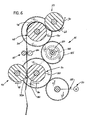
- the location of the fold on the sheets 30 can be adjusted, e.g. to alter or correct the undesirable fold condition shown at 185a in FIG. 6 and to attain a desired fold condition as shown at 185b in FIG. 7 .
- the user re-tightens handle 165 to clamp adjustment shaft 150 against rotation, to maintain the desired relative rotational positions of folding rolls 90, 95 relative to the lap roll 65.
- phase adjustment assembly 20 in accordance with the invention will be generally described with reference to an interfolding machine 25 for folding sheet material 30 into an interfolded, zig-zag stack 32
- the application of the phase adjustment assembly 20 can be applied to adjust phasing or timing of a wide variety of machines while in operation and is not limiting on the invention.
- phase adjustment between the rolls can also be accomplished using a single helical input gear and a single helical drive gear, to alter the rotational position of only a single one of the folding rolls.
Landscapes
- Engineering & Computer Science (AREA)
- Mechanical Engineering (AREA)
- Folding Of Thin Sheet-Like Materials, Special Discharging Devices, And Others (AREA)
Claims (8)
- Ineinanderfaltmaschine (25), umfassend:eine stromaufwärts liegende Walze (65), die an einer ersten Welle (182) montiert ist, und die betätigbar ist, um eine Reihe überlappender Bögen (30) in einer Richtung stromabwärts vorwärts zu bewegen, wobei eine vorderste Kante jedes Bogens in überlappender Beziehung, relativ zu dem nächsten, stromabwärts liegenden Bogen angeordnet ist;eine erste und eine zweite rotierende Falzwalze (90, 95), die einen Spalt dazwischen definieren, wobei wenigstens eine der ersten und zweiten rotierenden Falzwalzen (90, 95) an einer zweiten Welle (180) montiert ist, und wobei die stromaufwärts liegende Walze (65) die überlappenden Bögen in Richtung des Spalts zwischen der ersten und zweiten Falzwalze (90, 95) vorwärts bewegt, und wobei die erste und zweite Falzwalze (90, 95) derart konfiguriert sind, dass sie eine abwechselnd entgegengesetzt gerichtete Falz in jedem Bogen in dem Strom überlappender Bögen (30) in der Nähe der vordersten Kante des stromabwärts liegenden Bogens erzeugen; undeine Phaseneinstellvorrichtung, die dazwischen in Verbindung ist mit der stromaufwärts liegenden Walze (65) und einer der Falzwalzen (90, 95), zum Einstellen der Phase zwischen der stromaufwärts liegenden Walze (65) und einer der Falzwalzen (90, 95), um die Position einzustellen, bei der eine Falz in den Bögen ausgebildet wird, wenn die Bögen durch den Spalt zwischen der ersten und zweiten rotierenden Falzwalze (90, 95) vorwärts bewegt werden, wobei die Phaseneinstellvorrichtung umfasst:ein erstes Schrägverzahnungsgetriebe (130), das an der ersten Welle (132) befestigt ist;ein zweites Schrägverzahnungsgetriebe (120), das an der zweiten Welle (180) befestigt ist; undeine Eingabevorrichtung, die so konfiguriert ist, dass sie eine Rotationsbewegung der ersten Welle (182) über das erste Getriebe (130) und der zweiten Welle (180) über das zweite Getriebe (120) bewirkt, wobei die Eingabevorrichtung eine entgegengesetzt orientierte Schrägverzahnungsgetriebevorrichtung (125a, 125b) aufweist, die an einer axial beweglichen Eingabewelle (135) montiert ist, wobei eine axiale Bewegung der Eingabewelle (135) eine Rotationsbewegung des ersten und zweiten Getriebes (130, 120) bewirkt, um eine resultierende Rotationsbewegung der ersten und zweiten Welle zu bewirken und dabei der stromaufwärts liegenden Walze und einer der Falzwalzen, um die Phase der stromaufwärts liegenden Walze (65) relativ zu den Falzwalzen (90, 95) während eines Betriebs der Maschine zu ändern, wobei die Änderung der Phase der stromaufwärts liegenden Walze (65) relativ zu den Falzwalzen (90, 95) so funktioniert, dass eine Änderung des Orts der Falz in jedem Bogen erfolgt, wobei der Ort der Falz in jedem der Bögen relativ zu der hintersten Kante des stromabwärts liegenden Bogens geändert wird, um zu verhindern, dass die hinterste Kante des stromabwärts liegenden Bogens gefaltet wird, wenn die Falzwalzen so einwirken, dass sie den stromaufwärts liegenden Bogen, der an der hintersten Kante des stromabwärts liegenden Bogens angrenzt, falten.
- Ineinanderfaltmaschine nach Anspruch 1, wobei die Eingabevorrichtung aufweist:einen drehbaren Einstellungsbetätiger (160); undeine Einstellwelle (150), die mit dem Einstellungsbetätiger (150) gekoppelt ist, wobei eine Drehung des Einstellungsbetätigers (160) eine Drehung der Einstellwelle (150) bewirkt, und wobei die Rotationsbewegung der Einstellwelle (150) eine axiale Bewegung der Eingabewelle (135) bewirkt.
- Ineinanderfaltmaschine nach Anspruch 2, wobei die Eingabevorrichtung ferner aufweist:eine Sperrvorrichtung, die so konfiguriert ist, dass sie die Position der Einstellwelle (150) und dabei des ersten Getriebes (130) sichert.
- Ineinanderfaltmaschine nach Anspruch 2, wobei der Einstellungsbetätiger (150) untereinander verbunden ist mit der Eingabewelle (135) über eine mit Gewinde versehende Verbindung, die eine axiale Bewegung der Eingabewelle (135) bei einer Drehung des Einstellungsbetätigers (150) bewirkt.
- Ineinanderfaltmaschine nach Anspruch 1, wobei ein passendes, schrägverzahntes Eingabeelement (145) so konfiguriert ist, dass es eine selektive Bewegung des Schrägverzahnungsgetriebes (125a; 125b) entlang einer axialen Richtung bewirkt, wobei eine axiale Bewegung des Schrägverzahnungsgetriebes (125a; 125b) eine Phase der stromaufwärts liegenden Walze (65) relativ zu der Falzwalze (90) während eines Betriebs der Maschine (25) einstellt, bei dem die schrägverzahnten Eingabe- und Antriebsgetriebe (120, 130, 125a, 125b) zusammenwirken, um die Walzen (65, 90) zu drehen, mit denen die Schrägverzahnungsgetriebe (125a; 125b) verbunden sind.
- Ineinanderfaltmaschine nach Anspruch 5, wobei das zweite Schrägverzahnungsgetriebe in Eingriff steht mit dem Eingangsgetriebe und eine axiale Bewegung des die zweite Walze (95) drehenden Eingangsgetriebe eine Änderung der Phase der ersten rotierenden Walze (95) relativ zu der zweiten rotierenden Walze (95) bewirkt.
- Verfahren zum Einstellen einer Phase einer Ineinanderfaltmaschine nach einem der vorstehenden Ansprüche, die Schritte umfassend:Vorsehen einer Einstellvorrichtung für eine Walzenphase, die derart konfiguriert ist, dass sie die relativen rotationsmäßigen Positionen der ersten und zweiten rotierenden Walzen (90, 95) einstellt; undBetätigen der Einstellvorrichtung für die Walzenphase während eines Betriebs der Faltmaschine, um die Phase zwischen der ersten und zweiten Walze (90, 95) zu ändern.
- Verfahren nach Anspruch 7, wobei die Einstellvorrichtung für die Walzenphase passende schrägverzahnte Getriebe (120; 125a; 130, 125b) aufweist, von denen eines relativ zu dem anderen axial beweglich ist, und wobei der Schritt des Betätigens der Einstellvorrichtung für die Walzenphase durchgeführt wird, durch Bewegen eines ersten Getriebes (125a; 125b) entlang einer axialen Richtung in Reaktion auf eine drehbare Eingabevorrichtung (150), wobei eine Bewegung des ersten Getriebes in der axialen Richtung eine Einstellung der Phase der Walzen (90, 95) bewirkt.
Applications Claiming Priority (4)
| Application Number | Priority Date | Filing Date | Title |
|---|---|---|---|
| US50737703P | 2003-09-30 | 2003-09-30 | |
| US507377P | 2003-09-30 | ||
| US10/952,959 US7121994B2 (en) | 2003-09-30 | 2004-09-29 | Assembly for and method of adjusting the phasing of folding rolls to create a fold in sheets of material |
| US952959 | 2004-09-29 |
Publications (2)
| Publication Number | Publication Date |
|---|---|
| EP1520818A1 EP1520818A1 (de) | 2005-04-06 |
| EP1520818B1 true EP1520818B1 (de) | 2008-05-14 |
Family
ID=34316832
Family Applications (1)
| Application Number | Title | Priority Date | Filing Date |
|---|---|---|---|
| EP04256071A Expired - Lifetime EP1520818B1 (de) | 2003-09-30 | 2004-09-30 | Vorrichtung und Verfahren zum Verstellen der Phase von Falzwalzen in einer Ineinanderfaltmaschine |
Country Status (5)
| Country | Link |
|---|---|
| US (1) | US7121994B2 (de) |
| EP (1) | EP1520818B1 (de) |
| AT (1) | ATE395290T1 (de) |
| DE (1) | DE602004013696D1 (de) |
| ES (1) | ES2306964T3 (de) |
Families Citing this family (13)
| Publication number | Priority date | Publication date | Assignee | Title |
|---|---|---|---|---|
| US7364782B2 (en) * | 2000-07-24 | 2008-04-29 | High Voltage Graphics, Inc. | Flocked transfer and article of manufacture including the application of the transfer by thermoplastic polymer film |
| US7407161B2 (en) * | 2003-10-01 | 2008-08-05 | Fpna Acquisition Corporation | Method of and assembly for lapping consecutive sheets of web material |
| US7452321B2 (en) * | 2005-10-07 | 2008-11-18 | C.G. Bretting Manufacturing Company, Inc. | High speed interfolder |
| EP1826165B1 (de) | 2006-02-28 | 2009-09-16 | M T C - Macchine Trasformazione Carta S.r.l. | Modulare Ineinanderfaltmaschine geeignet für einfache Formatänderungen |
| US7717839B2 (en) * | 2008-04-04 | 2010-05-18 | C.G. Bretting Manufacturing Co., Inc. | Multi-path interfolding apparatus |
| ES2792374T3 (es) * | 2008-05-23 | 2020-11-11 | Mtc Macch Trasformazione Carta S R L | Estructura de máquina de plegado múltiple |
| US9371209B2 (en) * | 2012-05-01 | 2016-06-21 | C.G. Bretting Manufacturing Co., Inc. | Single path single web single-fold interfolder and methods |
| TWI483822B (zh) * | 2012-05-28 | 2015-05-11 | Chan Li Machinery Co Ltd | The cutting and folding of fibrous or plastic products |
| US10449746B2 (en) | 2016-06-27 | 2019-10-22 | C. G. Bretting Manufacturing Co., Inc. | Web processing system with multiple folding arrangements fed by a single web handling arrangement |
| TWI658983B (zh) * | 2018-05-24 | 2019-05-11 | 全利機械股份有限公司 | 纖維製品摺疊系統 |
| IT202100011531A1 (it) * | 2021-05-06 | 2022-11-06 | Koerber Tissue Fold S R L | Unita’ di piega, o interfogliatura, di fogli di carta in una macchina per la trasformazione della carta |
| CN118043274A (zh) * | 2021-08-20 | 2024-05-14 | 维美德造纸有限公司 | 用于生产由纸质材料制成的层状产品、特别是餐巾、纸巾或类似产品的包装的机器以及相关生产方法 |
| CN114520358B (zh) * | 2022-01-14 | 2024-02-23 | 江苏氢导智能装备有限公司 | 边框贴合装置 |
Family Cites Families (30)
| Publication number | Priority date | Publication date | Assignee | Title |
|---|---|---|---|---|
| US1789965A (en) * | 1929-06-12 | 1931-01-27 | Jr Peter J Christman | Mechanism for superimposing sheets of paper |
| US2092952A (en) * | 1934-11-26 | 1937-09-14 | Samuel J Campbell | Paper interfolding machine |
| US2555267A (en) | 1945-10-30 | 1951-05-29 | Goss Printing Press Co Ltd | All size folder |
| US2929624A (en) * | 1957-05-13 | 1960-03-22 | Jeyes Sanitary Compounds Compa | Apparatus for folding paper and like material |
| SE7702541L (sv) | 1977-03-07 | 1978-09-08 | Wifag Maschf | Sett och anordning att endra pappersformatet pa tryckmaskiner |
| US4159823A (en) | 1977-08-12 | 1979-07-03 | Wood Industries, Inc. | Multiple product folder |
| US4254947A (en) | 1979-05-30 | 1981-03-10 | C. G. Bretting Mfg. Co. Inc. | Sheet overlap device |
| JPS5699166A (en) | 1979-12-31 | 1981-08-10 | Tokyo Kikai Seisakusho:Kk | Device for adjusting folding line of cutting paper during operation of rotary press for printing |
| US4514819A (en) * | 1982-06-04 | 1985-04-30 | Harris Graphics Corporation | Apparatus and method for measuring rotational position |
| DE3726239A1 (de) | 1987-08-07 | 1989-02-16 | Frankenthal Ag Albert | Falzapparat |
| JPH01192669A (ja) | 1988-01-27 | 1989-08-02 | Komori Printing Mach Co Ltd | 輪転印刷機の折機 |
| DE3838314A1 (de) | 1988-11-11 | 1990-05-17 | Koenig & Bauer Ag | Falzklappenzylinder fuer eine rollenrotationsdruckmaschine |
| JP2815675B2 (ja) * | 1989-05-31 | 1998-10-27 | 東芝機械株式会社 | 複合型折機 |
| US5048387A (en) * | 1989-07-14 | 1991-09-17 | Komori Corporation | Horizontal perforation forming apparatus for rotary press |
| JP2801744B2 (ja) * | 1990-06-19 | 1998-09-21 | 株式会社小森コーポレーション | チョッパブレード動作時期自動制御方法及びその装置 |
| DE4103160C2 (de) | 1991-02-02 | 1994-09-08 | Roland Man Druckmasch | Falzapparat mit einem verstellbare Elemente, insbesondere Falzklappen oder bogenförmige Segmente, aufweisenden Falzwerkzylinder |
| DE4110035C2 (de) | 1991-03-27 | 1995-04-13 | Roland Man Druckmasch | Vorrichtung zum Verstellen von Elementen in Falzwerkzylindern von Rotationsdruckmaschinen |
| FR2680480B1 (fr) | 1991-08-19 | 1993-11-26 | Harris Marinoni Sa | Machine a couper et a plier une bande de papier imprime. |
| US5348527A (en) * | 1992-09-01 | 1994-09-20 | Rdp Marathon Inc. | Apparatus for cutting and stacking a multi-form web |
| JPH06255881A (ja) | 1993-03-03 | 1994-09-13 | Mitsubishi Heavy Ind Ltd | 新聞輪転機用折機のラップ調整装置 |
| US5405127A (en) | 1993-04-14 | 1995-04-11 | Didde Web Press Corporation | Signature folder apparatus for web fed printing press with sheet stop adjustment |
| US5571069A (en) | 1993-06-03 | 1996-11-05 | Shah; Chandrakant K. | Paper folding assembly with a cutting cylinder lap adjustment apparatus and method |
| JP3241181B2 (ja) | 1993-08-31 | 2001-12-25 | 三菱重工業株式会社 | 折機用咬え胴の咬え板間隔調整装置 |
| DE4426987C2 (de) | 1994-07-29 | 1998-10-22 | Roland Man Druckmasch | Falzapparat mit Formatumstellung |
| US5522586A (en) | 1994-09-07 | 1996-06-04 | Rockwell International Corporation | Folding apparatus with multiple speed folding jaw cylinder |
| FR2726259B1 (fr) | 1994-10-27 | 1997-01-17 | Heidelberg Harris Sa | Dispositif de changement de mode d'un cylindre d'accumulation d'une plieuse |
| DE19625083C1 (de) | 1996-06-22 | 1997-11-13 | Koenig & Bauer Albert Ag | Getriebe |
| DE19755428A1 (de) | 1997-12-13 | 1999-06-17 | Roland Man Druckmasch | Vorrichtung zum Verstellen der Falzmechanismen an einem Falzzylinder eines Falzapparates |
| US6428001B1 (en) | 2000-03-31 | 2002-08-06 | Heidelberger Druckmaschinen Ag | Signature slowdown apparatus |
| US6689038B2 (en) * | 2002-06-10 | 2004-02-10 | Fpna Acquisition Corporation | Method and apparatus for interrupting interfolded sheets created by a lapping interfolder |
-
2004
- 2004-09-29 US US10/952,959 patent/US7121994B2/en not_active Expired - Fee Related
- 2004-09-30 AT AT04256071T patent/ATE395290T1/de not_active IP Right Cessation
- 2004-09-30 EP EP04256071A patent/EP1520818B1/de not_active Expired - Lifetime
- 2004-09-30 DE DE602004013696T patent/DE602004013696D1/de not_active Expired - Lifetime
- 2004-09-30 ES ES04256071T patent/ES2306964T3/es not_active Expired - Lifetime
Also Published As
| Publication number | Publication date |
|---|---|
| US7121994B2 (en) | 2006-10-17 |
| DE602004013696D1 (de) | 2008-06-26 |
| ES2306964T3 (es) | 2008-11-16 |
| US20050070419A1 (en) | 2005-03-31 |
| EP1520818A1 (de) | 2005-04-06 |
| ATE395290T1 (de) | 2008-05-15 |
Similar Documents
| Publication | Publication Date | Title |
|---|---|---|
| EP1520818B1 (de) | Vorrichtung und Verfahren zum Verstellen der Phase von Falzwalzen in einer Ineinanderfaltmaschine | |
| JP3429739B2 (ja) | ニッピングローラーの間隙調整装置 | |
| US6358192B1 (en) | Device for adjusting folding jaws | |
| US6110093A (en) | Variable diameter roller | |
| US20100101386A1 (en) | Variable signature length web cutting apparatus | |
| GB2291862A (en) | Relatively positioning rotating parts,eg in a folding machine. | |
| US4971303A (en) | Paddle wheel distributor system for printed products | |
| EP0220644B1 (de) | Faltvorrichtung mit Vakuumsystem | |
| US7407161B2 (en) | Method of and assembly for lapping consecutive sheets of web material | |
| EP2284001B1 (de) | Hochgeschwindigkeitsinterfalzmaschine | |
| US6752751B2 (en) | Folder with multiple-motor drive | |
| US5692440A (en) | Cutting device | |
| US6331154B1 (en) | Pin action timing adjustment device in folding cylinder and folding device | |
| CA2483171C (en) | Assembly for and method of adjusting the phasing of folding rolls to create a fold in sheets of material | |
| US7326161B2 (en) | Folder | |
| US7115088B2 (en) | Folder cylinder with support plate | |
| JP4326195B2 (ja) | 折込ローラ装置 | |
| US6752078B2 (en) | Device for guiding flat or sheet-like copies in folders | |
| JP2987189B2 (ja) | 輪転印刷機の折機におけるデリバリガイド装置 | |
| JP2004322266A (ja) | スリッターナイフのカバー | |
| GB2272429A (en) | Drive arrangements for sheet feeding/cutting | |
| JP2004345817A (ja) | 折畳装置のペーパーガイド装置 | |
| JPWO2005105638A1 (ja) | 折機の平行折装置 | |
| JP2001253634A (ja) | ニッピングローラー装置 |
Legal Events
| Date | Code | Title | Description |
|---|---|---|---|
| PUAI | Public reference made under article 153(3) epc to a published international application that has entered the european phase |
Free format text: ORIGINAL CODE: 0009012 |
|
| AK | Designated contracting states |
Kind code of ref document: A1 Designated state(s): AT BE BG CH CY CZ DE DK EE ES FI FR GB GR HU IE IT LI LU MC NL PL PT RO SE SI SK TR |
|
| AX | Request for extension of the european patent |
Extension state: AL HR LT LV MK |
|
| 17P | Request for examination filed |
Effective date: 20051003 |
|
| AKX | Designation fees paid |
Designated state(s): AT BE BG CH CY CZ DE DK EE ES FI FR GB GR HU IE IT LI LU MC NL PL PT RO SE SI SK TR |
|
| 17Q | First examination report despatched |
Effective date: 20051107 |
|
| RTI1 | Title (correction) |
Free format text: ASSEMBLY FOR AND METHOD OF ADJUSTING THE PHASING OF FOLDING ROLLS IN AN INTERFOLDING MACHINE |
|
| GRAP | Despatch of communication of intention to grant a patent |
Free format text: ORIGINAL CODE: EPIDOSNIGR1 |
|
| GRAS | Grant fee paid |
Free format text: ORIGINAL CODE: EPIDOSNIGR3 |
|
| GRAA | (expected) grant |
Free format text: ORIGINAL CODE: 0009210 |
|
| AK | Designated contracting states |
Kind code of ref document: B1 Designated state(s): AT BE BG CH CY CZ DE DK EE ES FI FR GB GR HU IE IT LI LU MC NL PL PT RO SE SI SK TR |
|
| REG | Reference to a national code |
Ref country code: GB Ref legal event code: FG4D |
|
| REG | Reference to a national code |
Ref country code: CH Ref legal event code: EP |
|
| REG | Reference to a national code |
Ref country code: IE Ref legal event code: FG4D Free format text: LANGUAGE OF EP DOCUMENT: FRENCH |
|
| REF | Corresponds to: |
Ref document number: 602004013696 Country of ref document: DE Date of ref document: 20080626 Kind code of ref document: P |
|
| PG25 | Lapsed in a contracting state [announced via postgrant information from national office to epo] |
Ref country code: SI Free format text: LAPSE BECAUSE OF FAILURE TO SUBMIT A TRANSLATION OF THE DESCRIPTION OR TO PAY THE FEE WITHIN THE PRESCRIBED TIME-LIMIT Effective date: 20080514 |
|
| PG25 | Lapsed in a contracting state [announced via postgrant information from national office to epo] |
Ref country code: FI Free format text: LAPSE BECAUSE OF FAILURE TO SUBMIT A TRANSLATION OF THE DESCRIPTION OR TO PAY THE FEE WITHIN THE PRESCRIBED TIME-LIMIT Effective date: 20080514 |
|
| NLV1 | Nl: lapsed or annulled due to failure to fulfill the requirements of art. 29p and 29m of the patents act | ||
| REG | Reference to a national code |
Ref country code: ES Ref legal event code: FG2A Ref document number: 2306964 Country of ref document: ES Kind code of ref document: T3 |
|
| PG25 | Lapsed in a contracting state [announced via postgrant information from national office to epo] |
Ref country code: PL Free format text: LAPSE BECAUSE OF FAILURE TO SUBMIT A TRANSLATION OF THE DESCRIPTION OR TO PAY THE FEE WITHIN THE PRESCRIBED TIME-LIMIT Effective date: 20080514 Ref country code: NL Free format text: LAPSE BECAUSE OF FAILURE TO SUBMIT A TRANSLATION OF THE DESCRIPTION OR TO PAY THE FEE WITHIN THE PRESCRIBED TIME-LIMIT Effective date: 20080514 Ref country code: AT Free format text: LAPSE BECAUSE OF FAILURE TO SUBMIT A TRANSLATION OF THE DESCRIPTION OR TO PAY THE FEE WITHIN THE PRESCRIBED TIME-LIMIT Effective date: 20080514 |
|
| REG | Reference to a national code |
Ref country code: GB Ref legal event code: 732E |
|
| PG25 | Lapsed in a contracting state [announced via postgrant information from national office to epo] |
Ref country code: SE Free format text: LAPSE BECAUSE OF FAILURE TO SUBMIT A TRANSLATION OF THE DESCRIPTION OR TO PAY THE FEE WITHIN THE PRESCRIBED TIME-LIMIT Effective date: 20080814 Ref country code: CZ Free format text: LAPSE BECAUSE OF FAILURE TO SUBMIT A TRANSLATION OF THE DESCRIPTION OR TO PAY THE FEE WITHIN THE PRESCRIBED TIME-LIMIT Effective date: 20080514 Ref country code: DK Free format text: LAPSE BECAUSE OF FAILURE TO SUBMIT A TRANSLATION OF THE DESCRIPTION OR TO PAY THE FEE WITHIN THE PRESCRIBED TIME-LIMIT Effective date: 20080514 Ref country code: PT Free format text: LAPSE BECAUSE OF FAILURE TO SUBMIT A TRANSLATION OF THE DESCRIPTION OR TO PAY THE FEE WITHIN THE PRESCRIBED TIME-LIMIT Effective date: 20081014 |
|
| PG25 | Lapsed in a contracting state [announced via postgrant information from national office to epo] |
Ref country code: RO Free format text: LAPSE BECAUSE OF FAILURE TO SUBMIT A TRANSLATION OF THE DESCRIPTION OR TO PAY THE FEE WITHIN THE PRESCRIBED TIME-LIMIT Effective date: 20080514 Ref country code: SK Free format text: LAPSE BECAUSE OF FAILURE TO SUBMIT A TRANSLATION OF THE DESCRIPTION OR TO PAY THE FEE WITHIN THE PRESCRIBED TIME-LIMIT Effective date: 20080514 Ref country code: BE Free format text: LAPSE BECAUSE OF FAILURE TO SUBMIT A TRANSLATION OF THE DESCRIPTION OR TO PAY THE FEE WITHIN THE PRESCRIBED TIME-LIMIT Effective date: 20080514 |
|
| PLBE | No opposition filed within time limit |
Free format text: ORIGINAL CODE: 0009261 |
|
| STAA | Information on the status of an ep patent application or granted ep patent |
Free format text: STATUS: NO OPPOSITION FILED WITHIN TIME LIMIT |
|
| 26N | No opposition filed |
Effective date: 20090217 |
|
| PG25 | Lapsed in a contracting state [announced via postgrant information from national office to epo] |
Ref country code: MC Free format text: LAPSE BECAUSE OF NON-PAYMENT OF DUE FEES Effective date: 20080930 Ref country code: BG Free format text: LAPSE BECAUSE OF FAILURE TO SUBMIT A TRANSLATION OF THE DESCRIPTION OR TO PAY THE FEE WITHIN THE PRESCRIBED TIME-LIMIT Effective date: 20080814 Ref country code: EE Free format text: LAPSE BECAUSE OF FAILURE TO SUBMIT A TRANSLATION OF THE DESCRIPTION OR TO PAY THE FEE WITHIN THE PRESCRIBED TIME-LIMIT Effective date: 20080514 |
|
| REG | Reference to a national code |
Ref country code: CH Ref legal event code: PL |
|
| PG25 | Lapsed in a contracting state [announced via postgrant information from national office to epo] |
Ref country code: IE Free format text: LAPSE BECAUSE OF NON-PAYMENT OF DUE FEES Effective date: 20080930 |
|
| REG | Reference to a national code |
Ref country code: FR Ref legal event code: TP |
|
| PG25 | Lapsed in a contracting state [announced via postgrant information from national office to epo] |
Ref country code: CH Free format text: LAPSE BECAUSE OF NON-PAYMENT OF DUE FEES Effective date: 20080930 Ref country code: LI Free format text: LAPSE BECAUSE OF NON-PAYMENT OF DUE FEES Effective date: 20080930 |
|
| PG25 | Lapsed in a contracting state [announced via postgrant information from national office to epo] |
Ref country code: LU Free format text: LAPSE BECAUSE OF NON-PAYMENT OF DUE FEES Effective date: 20080930 Ref country code: HU Free format text: LAPSE BECAUSE OF FAILURE TO SUBMIT A TRANSLATION OF THE DESCRIPTION OR TO PAY THE FEE WITHIN THE PRESCRIBED TIME-LIMIT Effective date: 20081115 Ref country code: CY Free format text: LAPSE BECAUSE OF FAILURE TO SUBMIT A TRANSLATION OF THE DESCRIPTION OR TO PAY THE FEE WITHIN THE PRESCRIBED TIME-LIMIT Effective date: 20080514 |
|
| PG25 | Lapsed in a contracting state [announced via postgrant information from national office to epo] |
Ref country code: TR Free format text: LAPSE BECAUSE OF FAILURE TO SUBMIT A TRANSLATION OF THE DESCRIPTION OR TO PAY THE FEE WITHIN THE PRESCRIBED TIME-LIMIT Effective date: 20080514 |
|
| PG25 | Lapsed in a contracting state [announced via postgrant information from national office to epo] |
Ref country code: GR Free format text: LAPSE BECAUSE OF FAILURE TO SUBMIT A TRANSLATION OF THE DESCRIPTION OR TO PAY THE FEE WITHIN THE PRESCRIBED TIME-LIMIT Effective date: 20080815 |
|
| PGFP | Annual fee paid to national office [announced via postgrant information from national office to epo] |
Ref country code: IT Payment date: 20100928 Year of fee payment: 7 |
|
| PGFP | Annual fee paid to national office [announced via postgrant information from national office to epo] |
Ref country code: GB Payment date: 20110928 Year of fee payment: 8 Ref country code: FR Payment date: 20111005 Year of fee payment: 8 Ref country code: ES Payment date: 20110720 Year of fee payment: 8 Ref country code: DE Payment date: 20110928 Year of fee payment: 8 |
|
| GBPC | Gb: european patent ceased through non-payment of renewal fee |
Effective date: 20120930 |
|
| REG | Reference to a national code |
Ref country code: FR Ref legal event code: ST Effective date: 20130531 |
|
| PG25 | Lapsed in a contracting state [announced via postgrant information from national office to epo] |
Ref country code: GB Free format text: LAPSE BECAUSE OF NON-PAYMENT OF DUE FEES Effective date: 20120930 Ref country code: DE Free format text: LAPSE BECAUSE OF NON-PAYMENT OF DUE FEES Effective date: 20130403 |
|
| PG25 | Lapsed in a contracting state [announced via postgrant information from national office to epo] |
Ref country code: FR Free format text: LAPSE BECAUSE OF NON-PAYMENT OF DUE FEES Effective date: 20121001 Ref country code: IT Free format text: LAPSE BECAUSE OF NON-PAYMENT OF DUE FEES Effective date: 20120930 |
|
| REG | Reference to a national code |
Ref country code: DE Ref legal event code: R119 Ref document number: 602004013696 Country of ref document: DE Effective date: 20130403 |
|
| REG | Reference to a national code |
Ref country code: ES Ref legal event code: FD2A Effective date: 20131021 |
|
| PG25 | Lapsed in a contracting state [announced via postgrant information from national office to epo] |
Ref country code: ES Free format text: LAPSE BECAUSE OF NON-PAYMENT OF DUE FEES Effective date: 20121001 |