EP1520816A2 - Appareil de sortie et procédé correspondant - Google Patents
Appareil de sortie et procédé correspondant Download PDFInfo
- Publication number
- EP1520816A2 EP1520816A2 EP04022436A EP04022436A EP1520816A2 EP 1520816 A2 EP1520816 A2 EP 1520816A2 EP 04022436 A EP04022436 A EP 04022436A EP 04022436 A EP04022436 A EP 04022436A EP 1520816 A2 EP1520816 A2 EP 1520816A2
- Authority
- EP
- European Patent Office
- Prior art keywords
- delivery conveyor
- delivery
- speed
- drive
- conveyor
- Prior art date
- Legal status (The legal status is an assumption and is not a legal conclusion. Google has not performed a legal analysis and makes no representation as to the accuracy of the status listed.)
- Withdrawn
Links
Images





Classifications
-
- B—PERFORMING OPERATIONS; TRANSPORTING
- B65—CONVEYING; PACKING; STORING; HANDLING THIN OR FILAMENTARY MATERIAL
- B65H—HANDLING THIN OR FILAMENTARY MATERIAL, e.g. SHEETS, WEBS, CABLES
- B65H29/00—Delivering or advancing articles from machines; Advancing articles to or into piles
- B65H29/66—Advancing articles in overlapping streams
- B65H29/6609—Advancing articles in overlapping streams forming an overlapping stream
-
- B—PERFORMING OPERATIONS; TRANSPORTING
- B65—CONVEYING; PACKING; STORING; HANDLING THIN OR FILAMENTARY MATERIAL
- B65H—HANDLING THIN OR FILAMENTARY MATERIAL, e.g. SHEETS, WEBS, CABLES
- B65H29/00—Delivering or advancing articles from machines; Advancing articles to or into piles
- B65H29/16—Delivering or advancing articles from machines; Advancing articles to or into piles by contact of one face only with moving tapes, bands, or chains
-
- B—PERFORMING OPERATIONS; TRANSPORTING
- B65—CONVEYING; PACKING; STORING; HANDLING THIN OR FILAMENTARY MATERIAL
- B65H—HANDLING THIN OR FILAMENTARY MATERIAL, e.g. SHEETS, WEBS, CABLES
- B65H29/00—Delivering or advancing articles from machines; Advancing articles to or into piles
- B65H29/38—Delivering or advancing articles from machines; Advancing articles to or into piles by movable piling or advancing arms, frames, plates, or like members with which the articles are maintained in face contact
- B65H29/40—Members rotated about an axis perpendicular to direction of article movement, e.g. star-wheels formed by S-shaped members
-
- B—PERFORMING OPERATIONS; TRANSPORTING
- B65—CONVEYING; PACKING; STORING; HANDLING THIN OR FILAMENTARY MATERIAL
- B65H—HANDLING THIN OR FILAMENTARY MATERIAL, e.g. SHEETS, WEBS, CABLES
- B65H2301/00—Handling processes for sheets or webs
- B65H2301/10—Selective handling processes
- B65H2301/15—Selective handling processes of sheets in pile or in shingled formation
-
- B—PERFORMING OPERATIONS; TRANSPORTING
- B65—CONVEYING; PACKING; STORING; HANDLING THIN OR FILAMENTARY MATERIAL
- B65H—HANDLING THIN OR FILAMENTARY MATERIAL, e.g. SHEETS, WEBS, CABLES
- B65H2301/00—Handling processes for sheets or webs
- B65H2301/40—Type of handling process
- B65H2301/44—Moving, forwarding, guiding material
- B65H2301/447—Moving, forwarding, guiding material transferring material between transport devices
- B65H2301/4473—Belts, endless moving elements on which the material is in surface contact
- B65H2301/44732—Belts, endless moving elements on which the material is in surface contact transporting articles in overlapping stream
-
- B—PERFORMING OPERATIONS; TRANSPORTING
- B65—CONVEYING; PACKING; STORING; HANDLING THIN OR FILAMENTARY MATERIAL
- B65H—HANDLING THIN OR FILAMENTARY MATERIAL, e.g. SHEETS, WEBS, CABLES
- B65H2301/00—Handling processes for sheets or webs
- B65H2301/40—Type of handling process
- B65H2301/44—Moving, forwarding, guiding material
- B65H2301/447—Moving, forwarding, guiding material transferring material between transport devices
- B65H2301/4474—Pair of cooperating moving elements as rollers, belts forming nip into which material is transported
-
- B—PERFORMING OPERATIONS; TRANSPORTING
- B65—CONVEYING; PACKING; STORING; HANDLING THIN OR FILAMENTARY MATERIAL
- B65H—HANDLING THIN OR FILAMENTARY MATERIAL, e.g. SHEETS, WEBS, CABLES
- B65H2301/00—Handling processes for sheets or webs
- B65H2301/40—Type of handling process
- B65H2301/44—Moving, forwarding, guiding material
- B65H2301/447—Moving, forwarding, guiding material transferring material between transport devices
- B65H2301/44765—Rotary transport devices with compartments
-
- B—PERFORMING OPERATIONS; TRANSPORTING
- B65—CONVEYING; PACKING; STORING; HANDLING THIN OR FILAMENTARY MATERIAL
- B65H—HANDLING THIN OR FILAMENTARY MATERIAL, e.g. SHEETS, WEBS, CABLES
- B65H2301/00—Handling processes for sheets or webs
- B65H2301/40—Type of handling process
- B65H2301/44—Moving, forwarding, guiding material
- B65H2301/449—Features of movement or transforming movement of handled material
- B65H2301/4491—Features of movement or transforming movement of handled material transforming movement from continuous to intermittent or vice versa
-
- B—PERFORMING OPERATIONS; TRANSPORTING
- B65—CONVEYING; PACKING; STORING; HANDLING THIN OR FILAMENTARY MATERIAL
- B65H—HANDLING THIN OR FILAMENTARY MATERIAL, e.g. SHEETS, WEBS, CABLES
- B65H2513/00—Dynamic entities; Timing aspects
- B65H2513/10—Speed
-
- B—PERFORMING OPERATIONS; TRANSPORTING
- B65—CONVEYING; PACKING; STORING; HANDLING THIN OR FILAMENTARY MATERIAL
- B65H—HANDLING THIN OR FILAMENTARY MATERIAL, e.g. SHEETS, WEBS, CABLES
- B65H2513/00—Dynamic entities; Timing aspects
- B65H2513/40—Movement
Definitions
- the conventional delivery conveyor of a web rotary press uses a motor whose speed is variable in a broad range. This has posed the problem of necessitating an expensive motor having a large capacity.
- the present invention has solved the above-described problem in the following manner: If the printing press is operated at a speed higher than a certain drive speed, the delivery conveyor is continuously driven. If the printing press is operated at a speed lower than the certain drive speed, the delivery conveyor is intermittently driven. Moreover, the necessary variable speed range of the motor for driving is restricted to 25 times. Thus, an ordinary inexpensive small motor can be used.
- a delivery apparatus for attaining the above object, is a delivery apparatus having a delivery conveyor for receiving and transporting a printing product discharged from a printing press, characterized in that the delivery conveyor is continuously driven if a drive speed of the printing press is higher than a predetermined speed, or the delivery conveyor is intermittently driven if the drive speed of the printing press is lower than the predetermined speed.
- a drive speed of the delivery conveyor when intermittently driven may be a minimum drive speed of the delivery conveyor.
- a drive time and a stop time of the delivery conveyor when intermittently driven may be determined based on the drive speed of the printing press.
- a drive speed and a drive time of the delivery conveyor may be determined based on the drive speed of the printing press, and at a time when the printing product is completely discharged to the delivery conveyor, driving of the delivery conveyor may be started.
- a drive device for driving the delivery conveyor may be further included, and a maximum drive speed of the drive device may be not more than 25 times a minimum drive speed of the drive device.
- the eighth aspect of the invention there may be further included the steps of determining a drive speed and a drive time of the delivery conveyor based on the drive speed of the printing press when the delivery conveyor is to be intermittently driven, and starting driving of the delivery conveyor at a time when the printing product is completely discharged to the delivery conveyor.
- the drive time of the delivery conveyor when the delivery conveyor is intermittently driven may be a period of time from complete discharge of the printing product to the delivery conveyor until start of discharge of a next printing product to the delivery conveyor.
- a maximum drive speed of the delivery conveyor may be not more than 25 times a minimum drive speed of the delivery conveyor.
- the drive time of the delivery conveyor is determined based on the drive speed of the printing press, and after the printing product is completely discharged to the delivery conveyor, driving of the delivery conveyor is started.
- the delivery conveyor can be controlled reliably.
- FIG. 4 is a control block diagram of a delivery apparatus and a delivery method according to a first embodiment of the present invention.
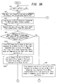
- Step Sa1 it is determined whether the start switch is ON. If ON, the program proceeds to Step Sa2.
- Step Sa2 the main unit speed for switching between continuous and intermittent operations is loaded from the memory 31 for the main unit speed for switching between continuous and intermittent operations.
- Step Sa3 a signal on the drive speed of the printing press 1 outputted from the A/D converter 44 connected to the main unit motor rotary encoder 27 is loaded.
- Step Sa4 the CPU 28 computes the drive speed of the printing press 1 from the signal loaded in Step Sa3, and stores the computed results in the current main unit speed memory 32.
- Step Sa8 the CPU 28 issues a minimum speed drive command to the delivery conveyor drive motor driver 46 to output a signal to the delivery conveyor drive motor 22 and drive it at the minimum speed.
- the delivery conveyor 9 is continuously driven. If the printing press 1 operates at a speed lower than the certain drive speed, the delivery conveyor 9 is intermittently driven. During the intermittent driving of the delivery conveyor 9 , the drive speed of the delivery conveyor 9 is a minimum speed. Moreover, the drive speed and the stop time of the delivery conveyor 9 are determined in accordance with the drive speed of the printing press 1.
- the delivery conveyor 9 can have a variable speed range.
- the delivery conveyor drive motor 22 is an inverter motor capable of convenient speed adjustment, and is of a general type having a rotational speed in a variable range of 100 to 2,500 rpm.
- FIG. 6 is a control block diagram of a delivery apparatus and a delivery method according to a second embodiment of the present invention. This embodiment involves changes in the features of the delivery conveyor control device 24.
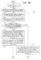
- Step Sb7 the phase of the main unit, in which the signature 15 is completely discharged from the fan wheel 12, is read from the memory 47 for a main unit phase for complete discharge of the signature.
- Step Sb8 a counted value is read from the main unit phase detection counter 48.
- Step Sb9 it is determined whether the counted value read in Step Sb8 is equal to the main unit phase for complete discharge of the signature 15 from the fan wheel 12 that was read in Step Sb7. If it is equal, the program proceeds to Step Sb10. If it is not equal, the program returns to Step Sb8 to continue processing.
- Step Sb16 the CPU 28 issues a stop command to the delivery conveyor drive motor driver 46 to output a signal to the delivery conveyor drive motor 22 and stop it.
- Step Sb18 it is determined whether the stop switch is ON. If ON, the control ends. If not ON, the program returns to Step Sb3 to continue processing.
- the drive time of the delivery conveyor 9 is determined based on the drive speed of the printing press 1, and after the signature 15 is completely discharged to the delivery conveyor 9, driving of the delivery conveyor 9 is started.
- the signature 15 is stably discharged to the delivery conveyor 9, and the intermittent drive time and the intermittent stop time of the delivery conveyor 9 can be controlled reliably.
- FIG. 8 is a control block diagram of a delivery apparatus and a delivery method according to a third embodiment of the present invention. This embodiment also involves changes in the features of the delivery conveyor control device 24.
- the delivery conveyor control device 24 comprises a CPU 28, an ROM 29, and an RAM 30, and also includes a memory 31 for a main unit speed for switching between continuous and intermittent operations, a current main unit speed memory 32 , a main unit speed-delivery conveyor drive motor continuous drive speed conversion table memory 33 , amain unit speed-delivery conveyor drivemotor intermittent drive speed conversion table memory 50, a main unit speed-delivery conveyor drive motor intermittent drive time conversion table memory 34, a delivery conveyor drive motor intermittent drive speed memory 51, a delivery conveyor drive motor continuous drive speed memory 36, a delivery conveyor drive motor intermittent drive time memory 37, and a memory 47 for a main unit phase for complete discharge of a signature from a fan wheel.
- These devices, these memories, input/output devices 39a to 39e, and an interface 40a are connected together by a bus-line BUS 52.
- the drive speed and the drive time of the delivery conveyor drive motor 22 are computed by the CPU 28 based on the drive speed of the printing press 1, and when the signature 15 is completely discharged to the delivery conveyor 9, driving of the delivery conveyor drive motor 22 is started.
- the drive time of the delivery conveyor drive motor 22 is a period of time from complete discharge of the signature 15 to the delivery conveyor 9 until start of discharge of a next signature 15 to the delivery conveyor 9.
- Step Sc1 it is determined whether the start switch is ON. If ON, the program proceeds to Step Sc2.
- Step Sc2 the main unit speed for switching between continuous and intermittent operations is loaded from the memory 31 for a main unit speed for switching between continuous and intermittent operations.
- Step Sc3 a signal on the drive speed of the printing press 1 outputted from the A/D converter 44 connected to the main unit motor rotary encoder 27 is loaded.
- Step Sc4 the CPU 28 computes the drive speed of the printing press 1 from the signal loaded in Step Sc3, and stores the computed results in the current main unit speed memory 32.
- Step Sc7 the CPU 28 finds the intermittent drive time of the delivery conveyor drive motor 22 with the use of the main unit speed-delivery conveyor drive motor intermittent drive time conversion table memory 34 based on the current main unit speed computed in Step Sc4. The results are stored in the delivery conveyor drive motor intermittent drive time memory 37.
- Step Sc16 it is determined whether the counted value of the internal clock is equal to the intermittent drive time of the delivery conveyor drive motor 22 found in Step Sc7. If it is equal, the program proceeds to Step Sc17. If it is not equal, the program returns to Step Sc14 to continue processing in the same manner.
- the drive speed and the drive time of the delivery conveyor 9 are determined based on the drive speed of the printing press 1, and after the signature 15 is completely discharged to the delivery conveyor 9, driving of the delivery conveyor 9 is started.
- the drive time of the delivery conveyor in this case is a period of time from complete discharge of the signature 15 to the delivery conveyor 9 until start of discharge of a next signature 15 to the delivery conveyor 9.
- the delivery conveyor 9 can be driven in agreement with the discharge cycle of the signature 15, and the delivery conveyor 9 can be stopped until discharge of the next signature 15.
- the signature 15 is stably discharged to the delivery conveyor 9.
- the signatures 15 can be discharged at predetermined intervals even with the use of an inexpensive small motor.
Landscapes
- Engineering & Computer Science (AREA)
- Mechanical Engineering (AREA)
- Delivering By Means Of Belts And Rollers (AREA)
- Pile Receivers (AREA)
- Separation, Sorting, Adjustment, Or Bending Of Sheets To Be Conveyed (AREA)
Applications Claiming Priority (2)
| Application Number | Priority Date | Filing Date | Title |
|---|---|---|---|
| JP2003342789A JP4230874B2 (ja) | 2003-10-01 | 2003-10-01 | 排紙装置及びその方法 |
| JP2003342789 | 2003-10-01 |
Publications (2)
| Publication Number | Publication Date |
|---|---|
| EP1520816A2 true EP1520816A2 (fr) | 2005-04-06 |
| EP1520816A3 EP1520816A3 (fr) | 2009-03-11 |
Family
ID=34309101
Family Applications (1)
| Application Number | Title | Priority Date | Filing Date |
|---|---|---|---|
| EP04022436A Withdrawn EP1520816A3 (fr) | 2003-10-01 | 2004-09-21 | Appareil de sortie et procédé correspondant |
Country Status (4)
| Country | Link |
|---|---|
| US (1) | US7377510B2 (fr) |
| EP (1) | EP1520816A3 (fr) |
| JP (1) | JP4230874B2 (fr) |
| CN (1) | CN1603218B (fr) |
Families Citing this family (1)
| Publication number | Priority date | Publication date | Assignee | Title |
|---|---|---|---|---|
| CN103588003A (zh) * | 2013-11-20 | 2014-02-19 | 上海航星机械(集团)有限公司 | 堆码输出机构传输方法 |
Family Cites Families (36)
| Publication number | Priority date | Publication date | Assignee | Title |
|---|---|---|---|---|
| US3945635A (en) * | 1974-07-19 | 1976-03-23 | Pitney-Bowes, Inc. | Power stacker |
| AT333193B (de) * | 1974-12-23 | 1976-11-10 | Gao Ges Automation Org | Ausschleus- und stapelvorrichtung fur flaches fordergut, wie papierbogen, belege u.dgl. |
| DE7619535U1 (de) * | 1976-06-19 | 1976-10-07 | Gustav Weyland Kg, 6740 Landau | Bogenauslagevorrichtung fuer rotationsdruckmaschinen |
| US4067568A (en) * | 1976-07-19 | 1978-01-10 | Pitney-Bowes, Inc. | Document feeding and stacking apparatus |
| US4088314A (en) * | 1977-04-22 | 1978-05-09 | Eastman Kodak Company | Synchronous stacking device |
| DE2756223C2 (de) * | 1977-12-16 | 1982-12-30 | GAO Gesellschaft für Automation und Organisation mbH, 8000 München | Verfahren zur Steuerung des Einlaufs von Transportgut in einen Spiralfachstapler und Vorrichtung zur Durchführung des Verfahrens |
| US4361318A (en) * | 1979-07-09 | 1982-11-30 | Stobb, Inc. | Apparatus and method for controlling sheet stacker speed |
| JPS57138847U (fr) * | 1981-02-24 | 1982-08-30 | ||
| US4638993A (en) * | 1981-06-29 | 1987-01-27 | Ncr Corporation | Position control for a stacker wheel |
| JPS59182156A (ja) * | 1983-03-31 | 1984-10-16 | Toshiba Corp | 紙葉類回収装置 |
| US4667951A (en) * | 1983-08-23 | 1987-05-26 | Canon Kabushiki Kaisha | Original feeding apparatus |
| DE3612021A1 (de) * | 1986-04-10 | 1987-10-15 | Will E C H Gmbh & Co | Vorrichtung zum arbeitstaktgerechten transport von blattlagen zu einer weiterverarbeitungsmaschine, beispielsweise zu einer verpackungsmaschine |
| SE458358B (sv) * | 1987-05-21 | 1989-03-20 | Pmb Vector Ab | Mottagningsanordning vid arktransportoer foer tillfaellig uppsamling av ark foere fortsatt transport |
| EP0316477A1 (fr) * | 1987-11-19 | 1989-05-24 | Drg (Uk) Limited | Procédé et dispositif pour traiter des feuilles |
| JP3245746B2 (ja) * | 1989-12-08 | 2002-01-15 | エス イー ゲー シュバイツェリッシェ インズストリー‐ゲゼルシャフト | 物品特にチョコレート棒用縦列形成装置 |
| US5186336A (en) * | 1991-01-22 | 1993-02-16 | Electrocom Automation L.P. | Product sorting apparatus |
| US5253860A (en) * | 1991-08-06 | 1993-10-19 | Ricoh Company, Ltd. | Finisher for an image forming apparatus |
| GB9207929D0 (en) * | 1992-04-10 | 1992-05-27 | Ncr Int Inc | Apparatus for loading sheets into a receptacle |
| DE69421783T2 (de) * | 1993-09-20 | 2000-07-06 | Kabushiki Kaisha Toshiba, Kawasaki | Vorrichtung zur Kontrolle von bogenförmigen Materialien und Transportvorrichtung für diese |
| US5501147A (en) * | 1993-10-05 | 1996-03-26 | Precision Screen Machines, Inc. | Automatic doffing system |
| IT1285693B1 (it) * | 1996-05-08 | 1998-06-18 | Azionaria Costruzioni Acma Spa | Metodo e dispositivo per l'alimentazione ordinaria di prodotti ricevuti alla rinfusa |
| JPH1111769A (ja) | 1997-06-26 | 1999-01-19 | Komori Corp | デリバリー装置 |
| JP3556848B2 (ja) * | 1998-12-21 | 2004-08-25 | 三菱重工業株式会社 | 折機の排紙ピッチ切り換え装置 |
| US6394445B1 (en) * | 1998-12-30 | 2002-05-28 | Quad/Tech, Inc. | Apparatus for slowing down and guiding a signature and method for doing the same |
| DE19904853A1 (de) * | 1999-02-05 | 2000-08-17 | Siemens Nixdorf Banking Syst | Verfahren und Vorrichtung zur Bildung eines Bündels von Einzelblättern |
| JP3032763B1 (ja) * | 1999-06-17 | 2000-04-17 | 株式会社東京機械製作所 | 輪転機におけるウエブ紙走行張力制御装置を備えた給紙部 |
| US6672586B2 (en) * | 1999-07-23 | 2004-01-06 | Canon Kabushiki Kaisha | Sheet processing apparatus and method of controlling same, sheet processing method, and storage media therefor |
| US6712356B2 (en) * | 2000-02-09 | 2004-03-30 | Mars Incorporated | Self aligning transport mechanism for media of variable media widths |
| US6494447B2 (en) * | 2000-06-13 | 2002-12-17 | Giesecke & Devrient America, Inc. | Stacker wheel control apparatus and method utilizing start-stop synchronization |
| JP2002003067A (ja) * | 2000-06-19 | 2002-01-09 | Nec Corp | プリンタ装置 |
| DE10030226A1 (de) * | 2000-06-20 | 2002-01-03 | Giesecke & Devrient Gmbh | Blattgutstapelvorrichtung und Verfahren zur Steuerung des Einlaufs von Blattgut in ein Staplerrad |
| JP4791631B2 (ja) * | 2000-12-26 | 2011-10-12 | 株式会社東芝 | 紙葉類処理装置 |
| ITBO20010394A1 (it) * | 2001-06-21 | 2002-12-21 | Azionaria Costruzioni Acma Spa | Unita' per l'alimentazione di una successione ordinata di prodotti aduna stazione di scarico |
| JP3622849B2 (ja) * | 2001-12-06 | 2005-02-23 | 株式会社東京機械製作所 | 折畳装置の紙詰り検出装置 |
| US6644645B2 (en) * | 2002-01-10 | 2003-11-11 | Gbr Systems Corporation | Stack control mechanism |
| JP3679391B2 (ja) * | 2002-10-22 | 2005-08-03 | 株式会社東京機械製作所 | 折機のデリバリー装置 |
-
2003
- 2003-10-01 JP JP2003342789A patent/JP4230874B2/ja not_active Expired - Fee Related
-
2004
- 2004-09-21 EP EP04022436A patent/EP1520816A3/fr not_active Withdrawn
- 2004-09-29 CN CN200410083268.2A patent/CN1603218B/zh not_active Expired - Fee Related
- 2004-09-30 US US10/952,851 patent/US7377510B2/en not_active Expired - Fee Related
Also Published As
| Publication number | Publication date |
|---|---|
| EP1520816A3 (fr) | 2009-03-11 |
| JP4230874B2 (ja) | 2009-02-25 |
| US7377510B2 (en) | 2008-05-27 |
| JP2005104686A (ja) | 2005-04-21 |
| US20050073086A1 (en) | 2005-04-07 |
| CN1603218B (zh) | 2010-05-05 |
| CN1603218A (zh) | 2005-04-06 |
Similar Documents
| Publication | Publication Date | Title |
|---|---|---|
| JP5255110B2 (ja) | 用紙後処理装置 | |
| US5826869A (en) | High throughput document-processing machine having dynamic speed control | |
| EP0522408A1 (fr) | Plieuse, en particulier pour des cahiers | |
| JP2008156113A (ja) | 用紙後処理装置および用紙後処理装置のブレード制御方法 | |
| EP1520816A2 (fr) | Appareil de sortie et procédé correspondant | |
| US20110058875A1 (en) | Sheet folding apparatus and image formation system provided with the apparatus | |
| US9193556B2 (en) | Sheet folding apparatus and image forming system | |
| CN114929487B (zh) | 在处理站停止传送元件而在其它处理站脱离传送元件的装订机 | |
| JP2008308341A (ja) | 排紙装置及びその方法 | |
| US9346256B2 (en) | Method for producing printed products | |
| EP3501838B1 (fr) | Système de reliure de livre en point sellier | |
| JP3878727B2 (ja) | 丁合装置 | |
| JP7067808B2 (ja) | 中綴じ製本システム及びその制御方法 | |
| NL1032054C2 (nl) | Werkwijze en bufferstation voor het bufferen van documenten. | |
| JP2635254B2 (ja) | 紙幣整理結束機 | |
| JP2000301493A (ja) | シートパンチ装置 | |
| JP2761570B2 (ja) | 媒体処理装置 | |
| JP3378650B2 (ja) | 自動原稿送り装置 | |
| EP1871610A2 (fr) | Procede pour transporter des feuilles dans une imprimante numerique | |
| JP4758267B2 (ja) | シート後処理装置、及び画像形成装置 | |
| JPH11263527A (ja) | 画像形成システム | |
| US20110293389A1 (en) | Method and system for producing a printed product | |
| JPH04125253A (ja) | 丁合システム | |
| JPH09235039A (ja) | 原稿搬送型画像読み取り装置 | |
| JPH0735038B2 (ja) | 発券装置 |
Legal Events
| Date | Code | Title | Description |
|---|---|---|---|
| PUAI | Public reference made under article 153(3) epc to a published international application that has entered the european phase |
Free format text: ORIGINAL CODE: 0009012 |
|
| AK | Designated contracting states |
Kind code of ref document: A2 Designated state(s): AT BE BG CH CY CZ DE DK EE ES FI FR GB GR HU IE IT LI LU MC NL PL PT RO SE SI SK TR |
|
| AX | Request for extension of the european patent |
Extension state: AL HR LT LV MK |
|
| PUAL | Search report despatched |
Free format text: ORIGINAL CODE: 0009013 |
|
| AK | Designated contracting states |
Kind code of ref document: A3 Designated state(s): AT BE BG CH CY CZ DE DK EE ES FI FR GB GR HU IE IT LI LU MC NL PL PT RO SE SI SK TR |
|
| AX | Request for extension of the european patent |
Extension state: AL HR LT LV MK |
|
| 17P | Request for examination filed |
Effective date: 20090317 |
|
| AKX | Designation fees paid |
Designated state(s): AT BE BG CH CY CZ DE DK EE ES FI FR GB GR HU IE IT LI LU MC NL PL PT RO SE SI SK TR |
|
| 17Q | First examination report despatched |
Effective date: 20100304 |
|
| STAA | Information on the status of an ep patent application or granted ep patent |
Free format text: STATUS: THE APPLICATION IS DEEMED TO BE WITHDRAWN |
|
| 18D | Application deemed to be withdrawn |
Effective date: 20100705 |